Embed Size (px)
Citation preview
APT REPORT
on
“MIGRATION STRATEGY OF GSM TO MOBILE BROADBAND”
No. APT/AWG/REP-53Edition: September 2014
Adopted by
17th Meeting of APT Wireless Group23 - 26, September 2014
Macao, China
(Source: AWG-17/OUT-11)
DRAFT REPORT ON “MIGRATION STRATEGY OF GSM TO MOBILE BROADBAND”
Contents1 Executive summary.................................................................................................................42 Current status of GSM spectrum.............................................................................................5
2.1 The band 815-960 MHz current usage in APT region......................................................52.2 Spectrum usage around 1800 MHz...................................................................................72.3 GSM spectrum license duration........................................................................................9
3 Progress of technology and industry to support the migration...............................................93.1 multi-RAT frequency resource allocation.......................................................................113.2 Non-standard frequency separation planning.................................................................123.3 Bufferzone solution.........................................................................................................133.4 Multi-Rat antenna solution..............................................................................................143.5 Power sharing between GSM/UMTS or GSM/LTE.......................................................153.6 GSM/UMTS Dynamic Spectrum Sharing......................................................................153.7 Spectrum sharing between GSM/UMTS or GSM/LTE..................................................153.8 Tight frequency reuse......................................................................................................15
4 Migration strategy.................................................................................................................164.1 How much 2G spectrum.................................................................................................164.2 Traffic balance between 900MHz and 1800MHz...........................................................164.3 GSM traffic migration to the UMTS/LTE......................................................................164.4 Low-band HSPA introduction........................................................................................164.5 Re-farming for high band LTE.......................................................................................17
5 Coexistence between GSM and IMT in the adjacent frequencies........................................185.1 Interference and intermodulation issues.........................................................................18
5.1.1 Interference..............................................................................................................185.1.2 Intermodulation........................................................................................................185.1.3 Guard Band and Carrier Separation.........................................................................18
5.2 Coexistence between GSM and WCDMA......................................................................195.2.1 Interference and site scenarios.................................................................................195.2.2 WCDMA DL capacity loss due to GSM.................................................................205.2.3 WCDMA UL capacity loss due to GSM.................................................................205.2.4 GSM UL capacity loss due to WCDMA.................................................................215.2.5 GSM DL capacity loss due to WCDMA.................................................................215.2.6 Summary..................................................................................................................21
5.3 Coexistence of Various 2G/3G/4G Technologies in Band 5 and Band 8.......................215.3.1 Inter-band and Intra-band Interference issues between Band 5 and Band 8............22
APT/AWG/REP-53 Page 2 of 55
5.3.2 Guard Band requirement in Inter-band case for cost-effective filtering..................245.4 Coexistence studies from CEPT between GSM and other systems................................24
6 General migration process....................................................................................................256.1 Feasibility Study.............................................................................................................266.2 Pre Re-farming actions....................................................................................................266.3 Frequency Plan elaboration & implementation..............................................................266.4 Post Re-farming actions..................................................................................................266.5 Performance Assessment................................................................................................26
7 Some case study....................................................................................................................267.1 General scenarios............................................................................................................277.2 Telstra LTE1800 Introduction........................................................................................29
8 Conclusion............................................................................................................................299 Reference..............................................................................................................................30ANNEX.........................................................................................................................................311 Interference issues around Band 5 and Band 8 Spectrum.....................................................312 Inter-band Interference issues between Band 5 and Band 8.................................................31
2.1 Inter-band Interference issues between CDMA850 and GSM900 systems....................332.2 Inter-band Interference issues between CDMA850 and UMTS900 systems.................342.3 Inter-band Interference Issues between CDMA850 and LTE900 Systems....................362.4 Inter-band Interference issues between UMTS850 and GSM900 systems:...................382.5 Inter-band Interference issues between UMTS850 and UMTS900 systems..................392.6 Inter-band Interference Issues between UMTS850 and LTE900 Systems.....................412.7 Inter-band Interference issues between LTE850 and GSM900 systems........................442.8 Inter-band Interference issues between LTE850 and UMTS900 systems......................452.9 Inter-band Interference Issues between LTE850 and LTE900 Systems.........................472.10 Additional ACLR & ACS requirement Summary with each interference scenario....49
3 Intra-band Interference Issues within Band 5/8 Spectrum....................................................514 Conclusions...........................................................................................................................54
APT/AWG/REP-53 Page 3 of 55
1 Executive summary
This Report deals with the migration strategy from GSM to Mobile Broadband network.
GSM networks, also known as 2G networks, have been deployed globally. With the current advancement of wireless communication technology, current mobile broadband networks offer much higher spectrum efficiency comparing with GSM systems. However, the newer systems are mainly deployed in higher frequency band, such as 2.1 GHz or 2.6 GHz. The high frequency bands make it costly for operators to deploy nation wide mobile broadband services. Therefore re-farming GSM bands is a natural solution to both maintaining current 2G service and at the same time provides cost effective solution for mobile broadband coverage in the rural areas.
In the nutshell re-farming is a strategy where telecom operators reuse their frequency resources to introduce new radio communication technologies to improve the spectral efficiency and data throughput. As users’ demand increases on data services, GSM is not sufficient to satisfy the users’ data need. For example, the mainstream 900 MHz re-farming solution is that operators free about 5 MHz of the GSM on the 900 MHz band and deploy UMTS on the 900 MHz frequency band.
GSM spectrum re-farming requires careful planning and management to guarantee a smooth transition to the Mobile Broadband networks. To serve this target, this Report will look into the following areas:
- Review status of 2G bands usage within the region.- Technical methods to re-arrange existing 2G spectrum.- Migration strategy. - Case studies of several successful re-farming.
APT/AWG/REP-53 Page 4 of 55
2 Current status of GSM spectrum
UMTS900 can complement 2100 MHz deployments to improve coverage, reduce CAPEX and OPEX, improve quality of service and enhance the user experience. UMTS900 operators can provide HSPA over much larger areas in a very cost-efficient way. GSM operators can also re-use many existing network assets e.g. antennas, network management systems when they migrate to UMTS900.
Currently there are 90 commercial UMTS900 networks in 53 countries1 and Regulators in at least 73 countries and territories allow or are considering UMTS900 deployments: Angola, Armenia, Australia, Austria, Belgium, Benin, Bosnia & Herzegovina, Bulgaria, Croatia, Cyprus, Denmark, Dominican Rep, Egypt, Estonia, Faroe Isles, Finland, France, French Guiana, Georgia, Germany, Ghana, Greece, Greenland, Guadeloupe, Hong Kong, Hungary, Iceland, Indonesia, Ireland, Israel, Italy, Japan, Kazakhstan, Kosovo, Kuwait, Latvia, Lithuania, Luxembourg, Macedonia, Malaysia, Malta, Martinique, Mozambique, Netherlands, New Caledonia, New Zealand, Norway, Oman, Papua New Guinea, Paraguay, Philippines, Poland, Portugal, Qatar, Réunion, Romania, Russia, Saudi Arabia, Singapore, Slovakia, Slovenia, South Africa, Spain, Sweden, Switzerland, Tanzania, Thailand, Tunisia, Turkey*, UAE, UK, Ukraine*, Venezuela (* = under consideration).
There is growing industry interest in 900 MHz as an LTE band. All the main infrastructure vendors offer LTE900 solutions. 5 operators (in the Czech Republic, South Korea, Sweden and Taiwan) have commercially launched LTE using 900 MHz either as a single band system, or as part of a multi-band deployment.2
However many additional operators are deploying or considering LTE using 900 MHz where this is feasible, including in Australia, Japan and elsewhere. With many GSM licenses approaching expiry dates, regulators often allow technology neutrality with renewal, or auction returned spectrum with technology neutrality licenses.
In Asia pacific countries, most of the providers use 900 MHz and 1800 MHz bands (5). GSM-900 is most widely used, and fewer operators use DCS-1800.
2.1 The band 815-960 MHz current usage in APT region
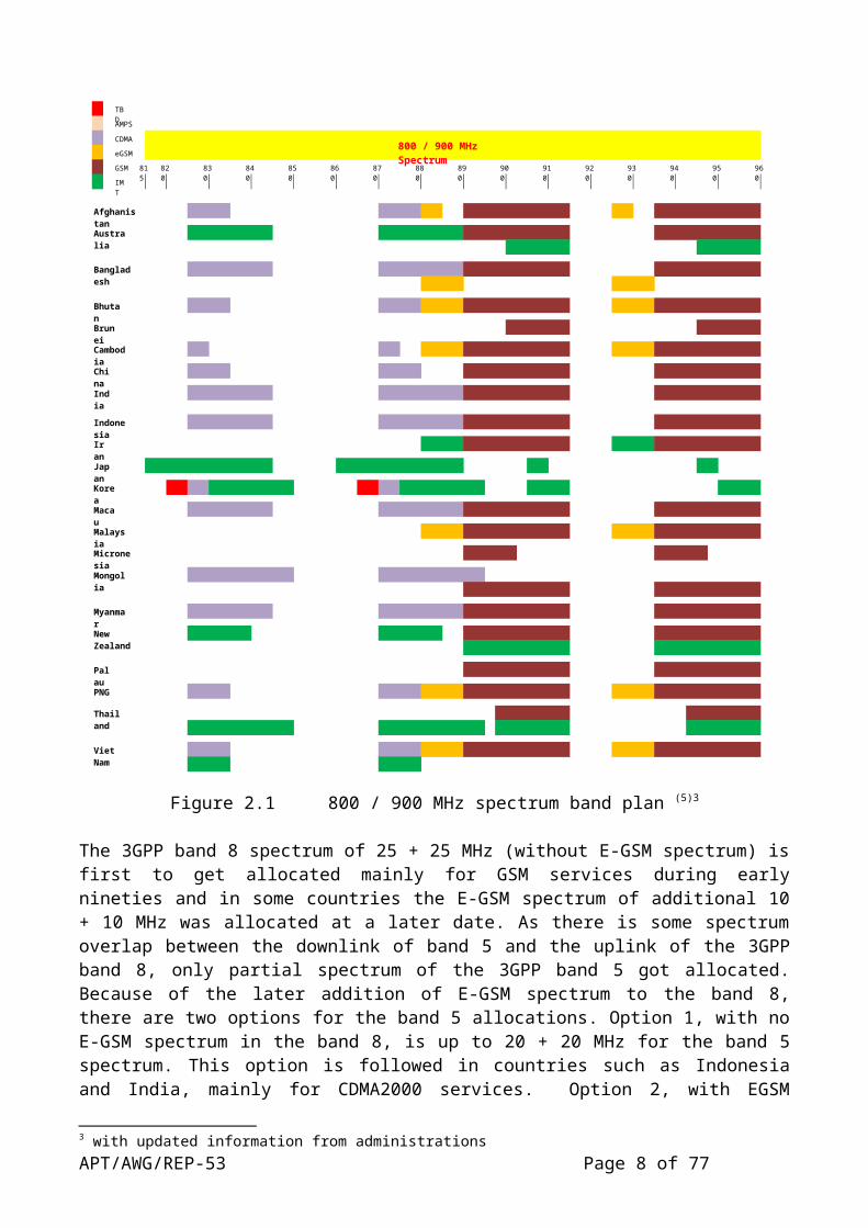
In the APT region, the two most popular spectrum bands for mobile wireless services are the 3GPP band 5 (850 MHz band) and band 8 (900 MHz band). Below Figure 2.1 is summarized from the APT Report APT/AWG/REP-15 (Rev.1) and relevant updated information from administrations for the 800/900 MHz spectrum. Most of countries have been operated GSM network in 3GPP band 8 (880 – 960 MHz). Several migration cases from GSM to IMT-2000 system could be seen in Australia and Thailand.
1 UMTS900 Global Status report: published by the GSA Global mobile Suppliers Association www.gsacom.com, 13 February 20142 LTE in 900 MHz spectrum (3G)) and 8) – market status, published by the GSA Global mobile Suppliers Association www.gsacom.com, 12 August 2014APT/AWG/REP-53 Page 5 of 55
TBD AMPS CDMA eGSM GSM IMT
Afghanistan Australia
Bangladesh
Bhutan Brunei Cambodia China India
Indonesia Iran Japan Korea Macau Malaysia Micronesia Mongolia
Myanmar New Zealand
Palau PNG Thailand
Viet Nam
890 940 830 820 860 800 / 900 MHz Spectrum
930 950 850 870 880 900 910 920 815 960 840
Figure 2.1 800 / 900 MHz spectrum band plan (5)3
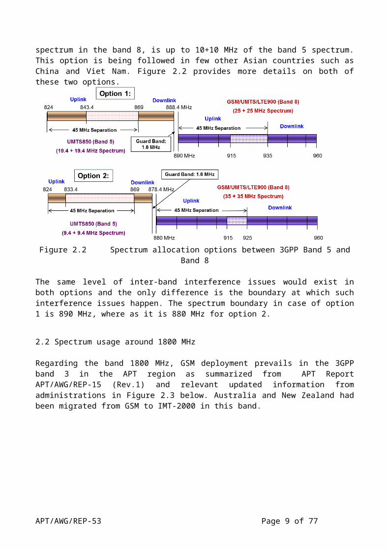
The 3GPP band 8 spectrum of 25 + 25 MHz (without E-GSM spectrum) is first to get allocated mainly for GSM services during early nineties and in some countries the E-GSM spectrum of additional 10 + 10 MHz was allocated at a later date. As there is some spectrum overlap between the downlink of band 5 and the uplink of the 3GPP band 8, only partial spectrum of the 3GPP band 5 got allocated. Because of the later addition of E-GSM spectrum to the band 8, there are two options for the band 5 allocations. Option 1, with no E-GSM spectrum in the band 8, is up to 20 + 20 MHz for the band 5 spectrum. This option is followed in countries such as Indonesia and India, mainly for CDMA2000 services. Option 2, with EGSM spectrum in the band 8, is up to 10+10 MHz of the band 5 spectrum. This option is being followed in few other Asian countries such as China and Viet Nam. Figure 2.2 provides more details on both of these two options.
3 with updated information from administrationsAPT/AWG/REP-53 Page 6 of 55
Figure 2.2 Spectrum allocation options between 3GPP Band 5 and Band 8
The same level of inter-band interference issues would exist in both options and the only difference is the boundary at which such interference issues happen. The spectrum boundary in case of option 1 is 890 MHz, where as it is 880 MHz for option 2.
2.2 Spectrum usage around 1800 MHz
Regarding the band 1800 MHz, GSM deployment prevails in the 3GPP band 3 in the APT region as summarized from APT Report APT/AWG/REP-15 (Rev.1) and relevant updated information from administrations in Figure 2.3 below. Australia and New Zealand had been migrated from GSM to IMT-2000 in this band.
APT/AWG/REP-53 Page 7 of 55
CDMA DECT GSM IMT
Afghanistan Australia
Bangladesh Bhutan
Brunei Cambodia China India Indonesia Iran Japan Korea Macau Malaysia Micronesia Mongolia
Myanmar New Zealand
Palau Papua New Guinea Thailand Viet Nam
1830 1840 1710 1720 1730 1740 1800 MHz Spectrum
1850 1860 1870 1880 1750 1760 1770 1780 1790 1800 1810 1820
Figure 2.3 1800 MHz spectrum band plan (5)4
GSM 1800 uses 1,710–1,785 MHz to send information from the mobile station to the base transceiver station (uplink) and 1,805–1,880 MHz for the other direction (downlink), providing 374 channels (channel numbers 512 to 885). Duplex spacing is 95 MHz. GSM-1800 is also called DCS-1800 (Digital Cellular Service) in some countries. Today, the 1800MHz band is often regarded as a higher band complement to GSM in the 900MHz band. Typically, the higher band is used for delivering capacity and the lower band for coverage.
There is high interest in re-farming 2G spectrum for LTE, especially 1800 MHz (3GPP band 3). Regulators generally adopt technology-neutrality to facilitate use for LTE-enabled mobile broadband and Internet access. In some markets 1800 MHz has been newly assigned for LTE systems. LTE network deployment in 1800 MHz is a main trend in most regions. 144 operators have commercially launched LTE1800 systems in 70 countries, either as a single band system, or within a multi-band deployment. LTE1800 serves millions of subscribers on over 45% of LTE networks worldwide.5
1800 MHz is easily the most widely used band for LTE deployments globally and its wide international footprint greatly assists international roaming.
Having regard to the scale of network deployments and maturity of the user devices ecosystem, LTE1800 is a mainstream mobile communications system technology.
4 With updated information from administrations5 Status of the Global LTE1800 Market, Report published by the GSA Global mobile Suppliers Association www.gsacom.com, 13 August 2014APT/AWG/REP-53 Page 8 of 55
The motivations for deploying LTE networks using 1800 MHz spectrum are clear:- Coverage area is approximately twice compared to deploying in 2.6 GHz band;- Possibility to re-use assets e.g. antenna cables of GSM1800 or WCDMA-HSPA2100;- Possibility to deploy multi-RAN with simultaneous LTE and GSM capabilities;- 1800 MHz band is widely available in Europe, APAC, MEA and parts of South America;- Operators often have sufficient bandwidth in 1800 MHz to secure the full benefits of LTE;- User device ecosystem is mature with an excellent choice of user devices;- Can be a transition strategy between HSPA and availability of new spectrum.
Regulators globally have increasingly adopted a technology neutral approach to mobile communications licensing, which has liberalized 1800 MHz for LTE-enabled mobile broadband.
2.3 GSM spectrum license duration
Since observes from (5), there is a fact that 2G/GSM spectrum license duration in band 800/900 or 1800 MHz do not have the same period and expired dates are quite different among licenses in most of countries. From Regulator view point, this practice may cause some difficulty in re-planning the spectrum in order to support the migration.
3 Progress of technology and industry to support the migration
In GSM centric markets, a typical operator would have between 7 to 10MHz of 900MHz spectrum and 10 to 15 MHz of 1800MHz for GSM. In addition to this, most of these operators also have between 10 to 15 MHz of 2100MHz for WCDMA.
As mobile penetration increased during the late 1990s, focus was put onto maximising spectrum efficiency to ensure GSM could carry as much voice and data capacity as possible. These spectrum efficient techniques were critical for markets such as the US and India to introduce high capacity GSM on limited spectrum (around or less than 5MHz). These techniques have been further developed over the years and are now vital to enable re-farming of current bands to make way for HSPA and LTE.
APT/AWG/REP-53 Page 9 of 55
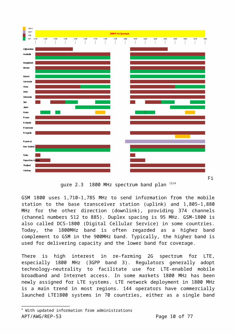
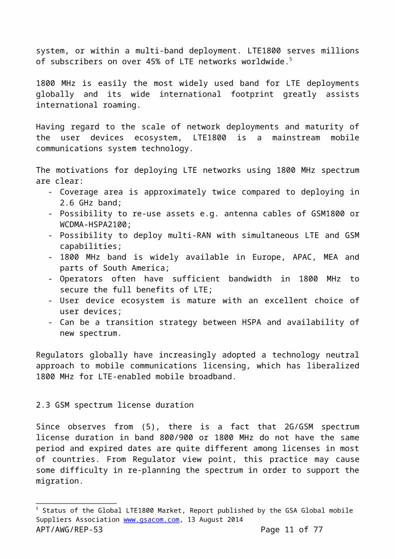
Figure 3.1 An example of spectrum strategy
The diagram above (Figure 3.1) shows the spectrum strategy for a leading operator. The first stage of the evolution shows the available spectrum along with the technology being deployed. As device capability increased, the 2100MHz spectrum was evolved to Dual Carrier HSPA which increased spectrum efficiency along with maximizing end user experience. Stage 2, HSPA900 introduction, was driven by Smartphone customer’s expectation that MBB coverage was everywhere. In addition to this, leading operators needed to secure technology leadership by introducing LTE quickly and as smoothly as possible. This is why GSM spectrum efficiency features and tighter cell planning techniques are critical to allow for re-farming.
According to GAMBoD (4), the GSA Analyzer for Mobile Broadband Devices, during Q1 2014 mobile subscriptions, there are 6.235 billion subscriptions globally using 3GPP systems (GSM, WCDMA-HSPA, LTE), includes 1.564 billion WCDMA subs including HSPA and 245.4 million LTE subs, and the 3GPP family occupies around 90% of 6.92 billion global mobile market.
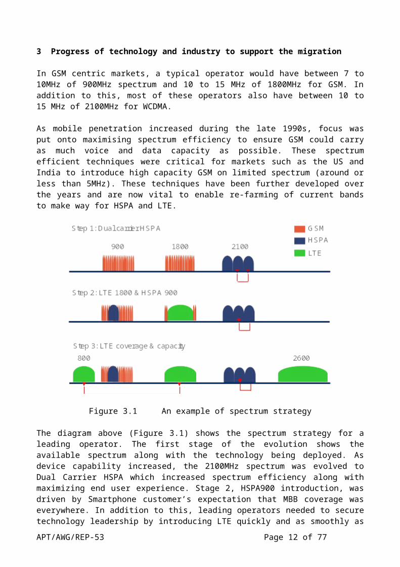
As of October 2012, there were more than 3847 commercial HSPA devices available worldwide from more than 285 suppliers (4), comprising handsets, smartphones, etc. Figure 3.2 shows the distribution of Frequency band used by the HSPA devices.
APT/AWG/REP-53 Page 10 of 55
800 850 900 1700 1800 1900 2100 AWS 0
500
1000
1500
2000
2500
3000
3500
HSPA devices
HSPA devices
Figure 3.2 Frequency bands of HSPA devices
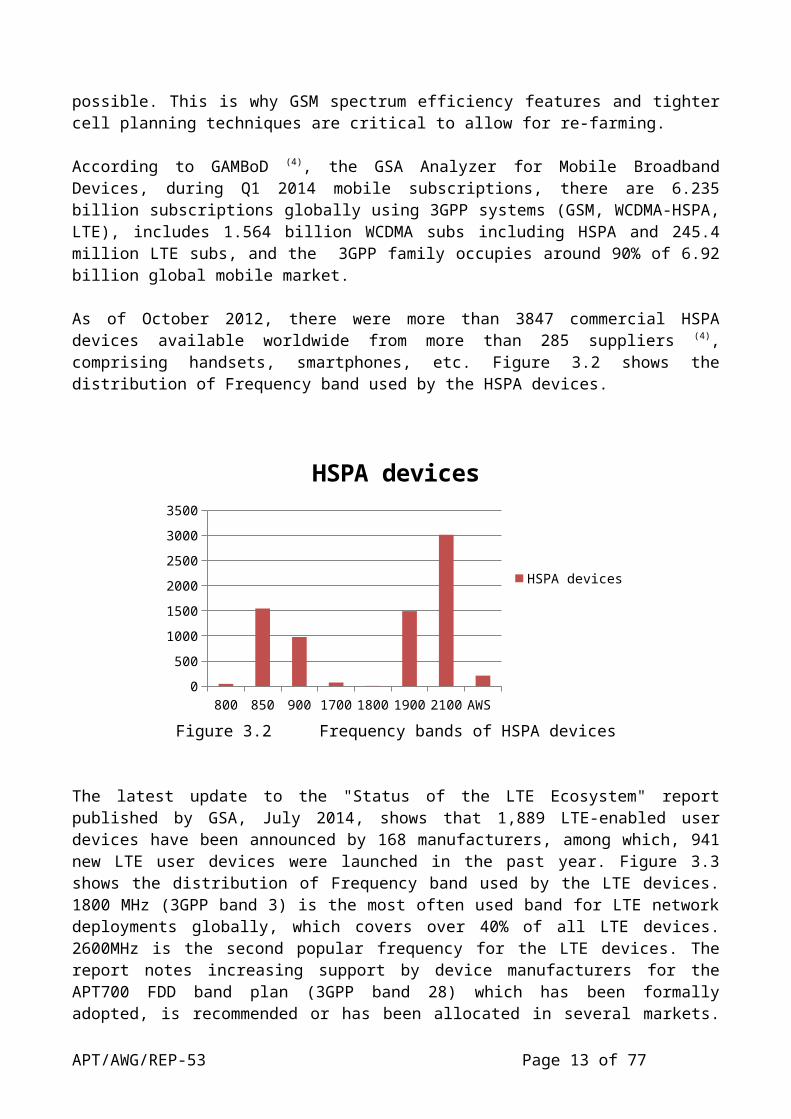
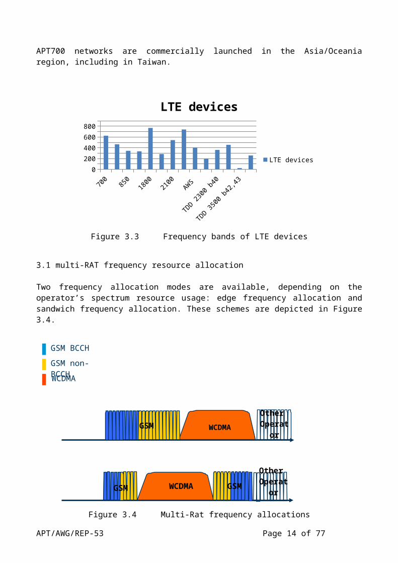
The latest update to the "Status of the LTE Ecosystem" report published by GSA, July 2014, shows that 1,889 LTE-enabled user devices have been announced by 168 manufacturers, among which, 941 new LTE user devices were launched in the past year. Figure 3.3 shows the distribution of Frequency band used by the LTE devices. 1800 MHz (3GPP band 3) is the most often used band for LTE network deployments globally, which covers over 40% of all LTE devices. 2600MHz is the second popular frequency for the LTE devices. The report notes increasing support by device manufacturers for the APT700 FDD band plan (3GPP band 28) which has been formally adopted, is recommended or has been allocated in several markets. APT700 networks are commercially launched in the Asia/Oceania region, including in Taiwan.
700800
850900
18001900
21002600
AWS
TDD 1900 b39
TDD 2300 b40
TDD 2600 b38, B
41
TDD 3500 b42,43
Others0
100200300400500600700800900
LTE devices
LTE devices
Figure 3.3 Frequency bands of LTE devices
3.1 multi-RAT frequency resource allocation
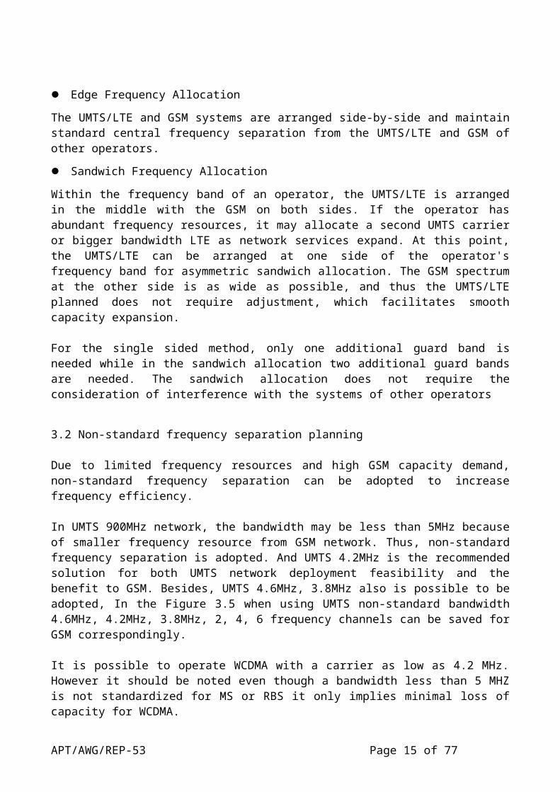
Two frequency allocation modes are available, depending on the operator’s spectrum resource usage: edge frequency allocation and sandwich frequency allocation. These schemes are depicted in Figure 3.4.APT/AWG/REP-53 Page 11 of 55
GSM BCCH
WCDMA
GSM non-BCCH
WCDMAGSMOther
Operator
WCDMAGSM GSMOther
Operator
Figure 3.4 Multi-Rat frequency allocations
Edge Frequency Allocation
The UMTS/LTE and GSM systems are arranged side-by-side and maintain standard central frequency separation from the UMTS/LTE and GSM of other operators.
Sandwich Frequency Allocation
Within the frequency band of an operator, the UMTS/LTE is arranged in the middle with the GSM on both sides. If the operator has abundant frequency resources, it may allocate a second UMTS carrier or bigger bandwidth LTE as network services expand. At this point, the UMTS/LTE can be arranged at one side of the operator's frequency band for asymmetric sandwich allocation. The GSM spectrum at the other side is as wide as possible, and thus the UMTS/LTE planned does not require adjustment, which facilitates smooth capacity expansion.
For the single sided method, only one additional guard band is needed while in the sandwich allocation two additional guard bands are needed. The sandwich allocation does not require the consideration of interference with the systems of other operators
3.2 Non-standard frequency separation planning
Due to limited frequency resources and high GSM capacity demand, non-standard frequency separation can be adopted to increase frequency efficiency.
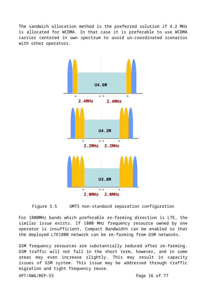
In UMTS 900MHz network, the bandwidth may be less than 5MHz because of smaller frequency resource from GSM network. Thus, non-standard frequency separation is adopted. And UMTS 4.2MHz is the recommended solution for both UMTS network deployment feasibility and the benefit to GSM. Besides, UMTS 4.6MHz, 3.8MHz also is possible to be adopted, In the Figure 3.5 when using UMTS non-standard bandwidth 4.6MHz, 4.2MHz, 3.8MHz, 2, 4, 6 frequency channels can be saved for GSM correspondingly.
APT/AWG/REP-53 Page 12 of 55
2.4MHz 2.4MHz
U4.6M
2.2MHz2.2MHz
U4.2M
2.0MHz2.0MHz
U3.8M
It is possible to operate WCDMA with a carrier as low as 4.2 MHz. However it should be noted even though a bandwidth less than 5 MHZ is not standardized for MS or RBS it only implies minimal loss of capacity for WCDMA.
The sandwich allocation method is the preferred solution if 4.2 MHz is allocated for WCDMA. In that case it is preferable to use WCDMA carrier centered in own spectrum to avoid un-coordinated scenarios with other operators.
Figure 3.5 UMTS non-standard separation configuration
For 1800MHz bands which preferable re-farming direction is LTE, the similar issue exists. If 1800 MHz frequency resource owned by one operator is insufficient, Compact Bandwidth can be enabled so that the deployed LTE1800 network can be re-farming from GSM networks.
GSM frequency resources are substantially reduced after re-farming. GSM traffic will not fall in the short term, however, and in some areas may even increase slightly. This may result in capacity issues of GSM system. This issue may be addressed through traffic migration and tight frequency reuse.
3.3 Bufferzone solution
APT/AWG/REP-53 Page 13 of 55
In the case of GSM and UMTS/LTE co-channel interference, a space separation is required to reduce the co-channel interference. Areas with UMTS/LTE networks deployed and their peripheral areas form a band-type area. In this area, GSM networks cannot use frequencies overlapped in UMTS/LTE frequency spectrums and therefore GSM network capacity decreases. A large space separation for co-channel interference decreases impacts of GSM and UMTS/LTE co-channel interference on network performance. For space separation for co-channel interference, buffer zone planning solution is based on emulation and onsite traffic statistics to accommodate different scenarios.
3.4 Multi-Rat antenna solution
After GSM re-farming, UMTS/LTE networks deployed may use three antenna feeder solutions, as shown in Figure 3.6:
Separate antenna feeder solution Four-port shared antenna feeder solution Two-port shared antenna feeder solution
Figure 3.6 GSM and UMTS/LTE antenna feeder solutions
The three antenna feeder solutions are different in deployment scenarios and requirements for investment and performance. Here BTS1 and BTS2 are employed different RATs, and MBTS is the MSR BTS.
Whichever antenna feeder solution is used for UMTS/LTE deployment, RF planning is required. However, the three antenna feeder solutions have different requirements for RF planning and the RF planning complexity is also different.
- The separate antenna feeder solution uses a separate antenna and aims to achieve the optimal UMTS/LTE performance.
- The four-port shared antenna feeder solution aims to achieve the optimal LTE performance and minimize impacts on GSM services on the live network.
- The two-port shared antenna feeder solution aims to achieve a relatively optimal UMTS/LTE performance with acceptable impacts on GSM services on the live network. This solution costs the minimum among the three antenna feeder solutions because it allows that the newly deployed UMTS/LTE site reuses the original GSM antenna system. However, in preliminary planning, this solution requires emulation and onsite data for evaluating impacts of antenna feeder parameters on GSM and UMTS/LTE network performance.
APT/AWG/REP-53 Page 14 of 55
More and more operators would like to use multi-port and multi-band antenna, there will be only one antenna in one cell. This modification recently becomes more and more popularly.
It could be better to modernization of the hardware if re-farming is performed. i.e. use multi-standard products able to operate in mixed mode, which can both improve receiver sensitivity at the BTS and remove the need for combiners, reducing the signal loss.
3.5 Power sharing between GSM/UMTS or GSM/LTE
With Mixed Mode GSM/UMTS or GSM/LTE base station, UMTS High Speed Downlink Packet Access (HSDPA)/LTE cells can share the idle carrier power provided by the GSM cells. Thanks to the Intelligent Power Management, GSM power control features and behavior of GSM traffic bursts, the GSM cells can be configured with more total power than what is nominally available, without degrading KPIs. This means that UMTS/LTE can be configured to a higher power level, thereby letting GSM have a smaller portion of the total available power, while still keeping the GSM coverage and capacity. The power sharing and retrieval help improve the power usage efficiency and the UMTS/LTE network quality when busy hours of the GSM and UMTS/LTE networks fall in different periods or different positions.
3.6 GSM/UMTS Dynamic Spectrum Sharing
In areas with both GSM and UMTS coverage, the GSM network can dynamically share its spectral resources with the UMTS network based on the service load on both networks. This sharing mechanism improves spectral efficiency. Some of the idle GSM spectral resources can be shared with the UMTS network when the service load on the GSM network is below a specific threshold. When the service load on the GSM network is above a specific threshold, the GSM network reclaims the shared spectral resources. UMTS has higher spectral efficiency than GSM. Therefore, GSM and UMTS Dynamic Spectrum Sharing (DSS) increases network throughput and reduces the composite costs of data services.
3.7 Spectrum sharing between GSM/UMTS or GSM/LTE
In areas with both GSM and UMTS/LTE coverage, the spectral resources can be shared with GSM network and the UMTS/LTE network based on the service load on both networks. This sharing mechanism improves spectral efficiency. Some of the idle GSM spectral resources can be shared with the UMTS/LTE network when the service load on the GSM network is below a specific threshold. When the service load on the GSM network is above a specific threshold, the GSM network reclaims the shared spectral resources. UMTS/LTE has higher spectral efficiency than GSM. Therefore, the network throughput can be increased and the composite costs of data services can be reduced with spectrum sharing between GSM/UMTS or GSM/LTE.
3.8 Tight frequency reuse
The 1/1 or 1/3 RF hopping solution can be adopted to achieve a tighter frequency reuse. In this case, interference suppression technology should be applied in conjunction with conventional power control and DTX. Interference planning based on network synchronization can also be utilized.
APT/AWG/REP-53 Page 15 of 55
4 Migration strategy
4.1 How much 2G spectrum
Rather than deciding how much spectrum to leave, the question should be how efficiently used is the GSM spectrum today. Spectrum re-farming can be performed in steps and will continue as traffic begins to migrate to the newer technologies.
One of the first considerations for re-farming is to determine the spectral efficiency of a GSM network considering current traffic load. Many networks have been built over several years and are far from optimal. Using global operator benchmarking, a network can be easily assessed to determine the potential for re-farming. Typically, most operators have some room for either or both HSPA 900 and LTE 1800. One of the most important aspects of improving spectrum efficiency is to ensure that the fundamental cell plan is as optimal as possible through correct site locations, parameter settings and antenna positioning. Once these are in place, further efficiency improvements can be achieved through advanced software along with further parameter optimization.
4.2 Traffic balance between 900MHz and 1800MHz
Most operators have both 900MHz and 1800MHz frequency resources, and most current UEs support both GSM900 and GSM1800, so traffic should be balanced between 900MHz and 1800MHz. GSM 1800MHz TRX should be expanded in some scenario. If conditions are met, Co-BCCH networking or dual-frequency networking between 900MHz and 1800MHz can be adopted to increase the frequency efficiency. Correspondingly, cell reselection and handover parameters should also be designed.
4.3 GSM traffic migration to the UMTS/LTE
When UMTS/LTE is deployed, some CS/PS traffic can be migrated to UMTS/LTE, and hence the capacity demand of GSM will decrease. But this strategy depends on the penetration of UEs that are supported UMTS/LTE. Also the operators’ fare strategy can have the impact the migration volume.
4.4 Low-band HSPA introduction
Introducing 5MHz of HSPA into the 900MHz band is an excellent way to increase overall MBB coverage since HSPA900MHz has approximately 6dB better coverage than HSPA2100MHz. Removing 5MHz of GSM to make way for HSPA requires careful planning but is achievable, as can be seen in the following example.
An Asian operator with 10MHz of GSM 900MHz and 15MHz of GSM 1800MHz plus 10MHz WCDMA 2100MHz planned to introduce 5 MHz of HSPA900.The required capacity in the G900 network is achieved through tighter cell planning, basic & advanced software features and optimization. Utilizing synthesized frequency hopping, optimizing antenna tilts and by managing interference with software features all lead to increased spectral efficiency thereby allowing the same traffic to be carried in less spectrum. Traffic management in GSM is also very powerful since traffic can be seamlessly moved between bands to manage capacity with no impact on end user experience.
APT/AWG/REP-53 Page 16 of 55
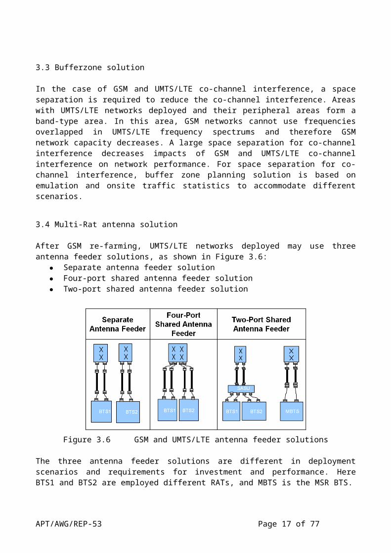
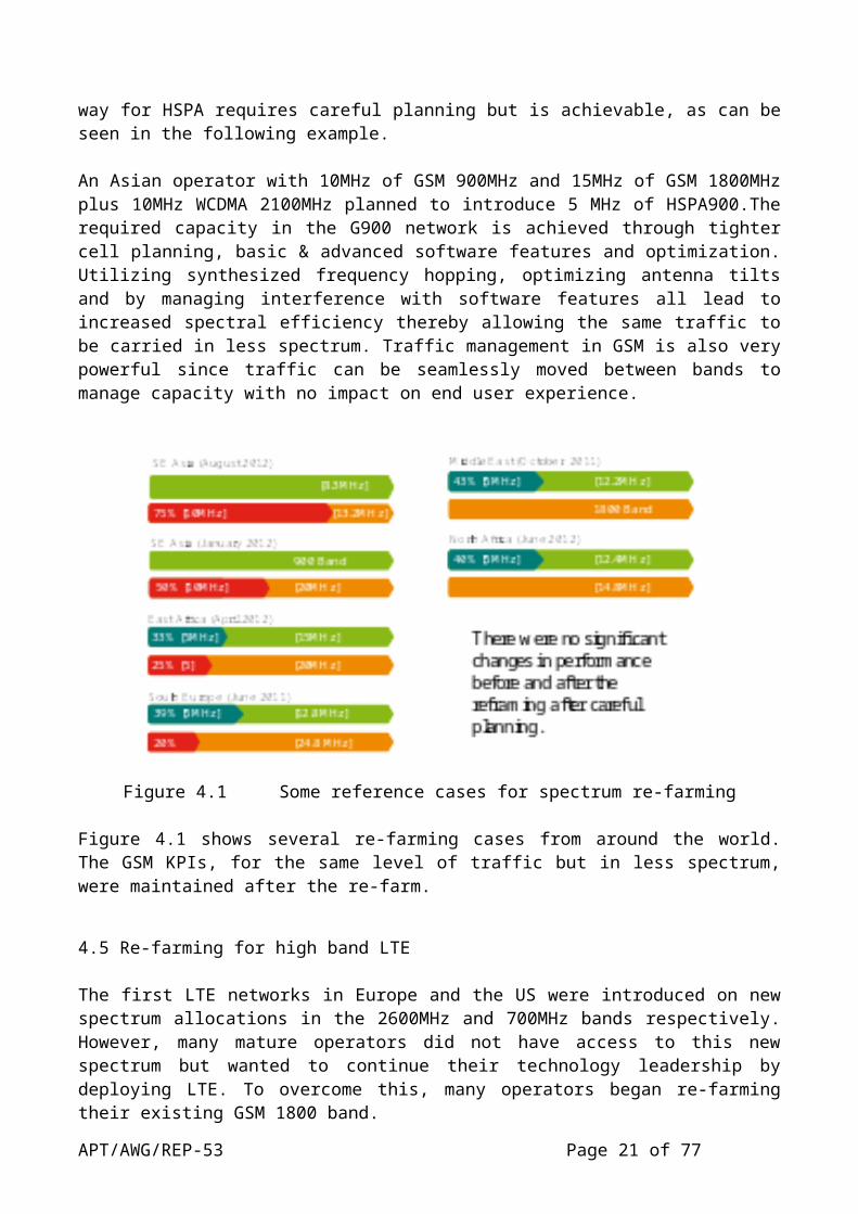
Figure 4.1 Some reference cases for spectrum re-farming
Figure 4.1 shows several re-farming cases from around the world. The GSM KPIs, for the same level of traffic but in less spectrum, were maintained after the re-farm.
4.5 Re-farming for high band LTE
The first LTE networks in Europe and the US were introduced on new spectrum allocations in the 2600MHz and 700MHz bands respectively. However, many mature operators did not have access to this new spectrum but wanted to continue their technology leadership by deploying LTE. To overcome this, many operators began re-farming their existing GSM 1800 band.
Before planning the introduction of LTE, sufficient spectrum should be secured for HSPA to deliver broad coverage and good user experience. Typically this means securing a combination of 15 – 25MHZ of low and high band spectrum. In Asian markets, operators use a combination of 850MHz and 900MHz for the low band and 2100MHz for the high band HSPA. Telstra in Australia, for example, has 10MHz of 850MHZ and 15MHz of 2100MHz. The low band 850MHz provides a strong coverage layer across the whole country with HSPA 2100MHz providing capacity relief in built up areas.
When Telstra wanted to introduce LTE and 2600MHz was not available, 1800MHz was the obvious band. As part of their long term strategy Telstra stopped selling GSM devices in 2006 meaning that the traffic level on GSM had dropped considerably by the time they considered LTE in 2011. To accommodate LTE 1800, the GSM traffic was pushed back onto the 900MHz layer by optimizing and increasing the GSM 900 spectrum efficiency in a similar way described previously.
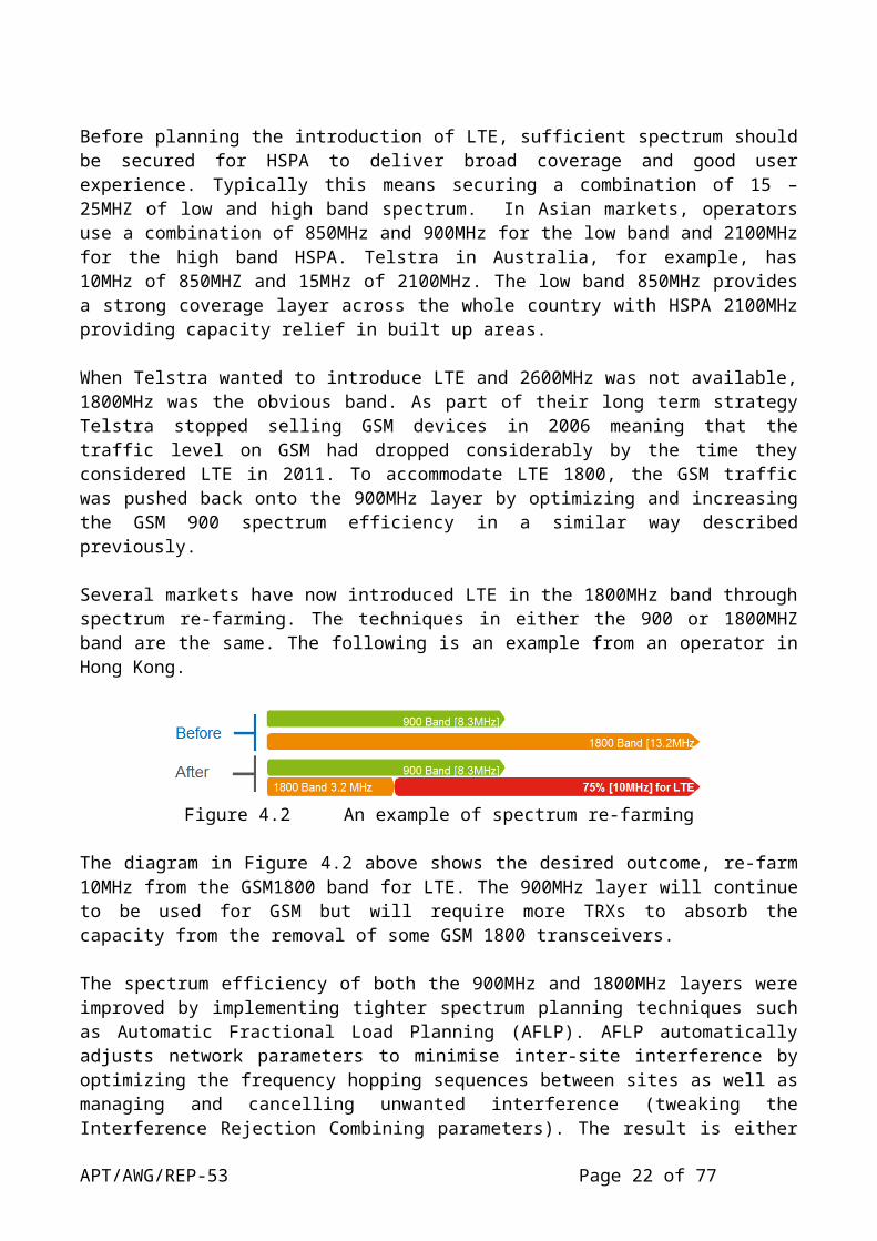
Several markets have now introduced LTE in the 1800MHz band through spectrum re-farming. The techniques in either the 900 or 1800MHZ band are the same. The following is an example from an operator in Hong Kong.
APT/AWG/REP-53 Page 17 of 55
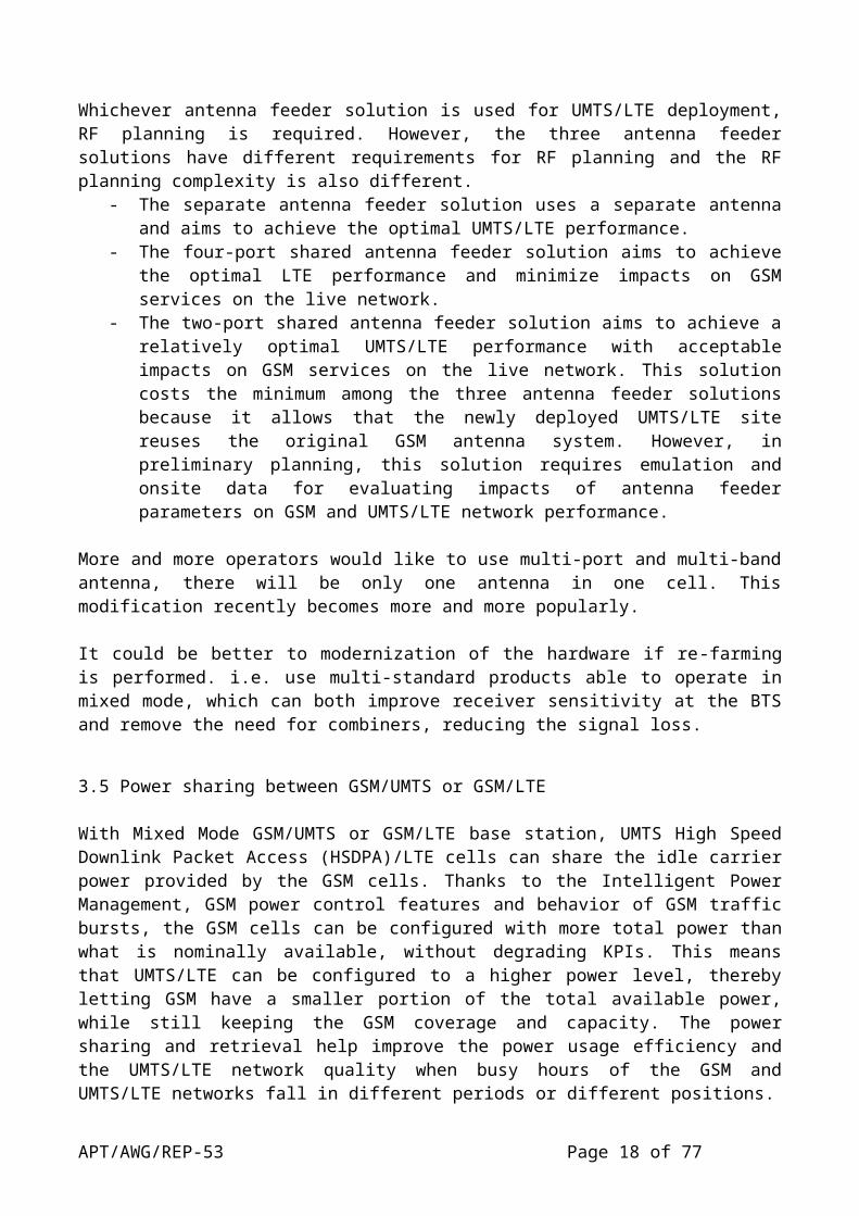
Figure 4.2 An example of spectrum re-farming
The diagram in Figure 4.2 above shows the desired outcome, re-farm 10MHz from the GSM1800 band for LTE. The 900MHz layer will continue to be used for GSM but will require more TRXs to absorb the capacity from the removal of some GSM 1800 transceivers.
The spectrum efficiency of both the 900MHz and 1800MHz layers were improved by implementing tighter spectrum planning techniques such as Automatic Fractional Load Planning (AFLP). AFLP automatically adjusts network parameters to minimise inter-site interference by optimizing the frequency hopping sequences between sites as well as managing and cancelling unwanted interference (tweaking the Interference Rejection Combining parameters). The result is either more traffic in the same spectrum or same traffic in less spectrum. In this case, the 900MHz layer carried more traffic and the GSM allocation on the 1800MHz layer was reduced. There were no significant changes in key performance indicators after this re-farm.
5 Coexistence between GSM and IMT in the adjacent frequencies
5.1 Interference and intermodulation issues
5.1.1 Interference
When GSM re-farming is implemented, except for interference between GSM and UMTS/LTE under standard separation or non-standard separation, narrow band interference in UMTS/LTE network is stricter. The narrow band interference may be from GSM TRXs that are not cleared completely, or may be from external interference source, like traffic light, broadcast signal, etc. These interference signals are not constant, and their strength is variable.
5.1.2 Intermodulation
Intermodulation problems can occur after GSM re-farming, when GSM will coexist with UMTS or LTE in one band. The intermodulation may be caused by antenna aging, feeder/jumper connection loose, etc., which will also exist in all other RAT combinations as well (as well as single RAT GSM operation).
5.1.3 Guard Band and Carrier Separation
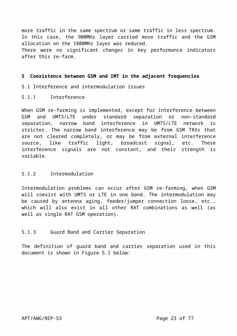
The definition of guard band and carrier separation used in this document is shown in Figure 5.1 below:
APT/AWG/REP-53 Page 18 of 55
Figure 5.1 Carrier separation and guard band
Carrier separation: the frequency band between two carrier centers.Guard band: the unutilized frequency band between two carriers.
5.2 Coexistence between GSM and WCDMA
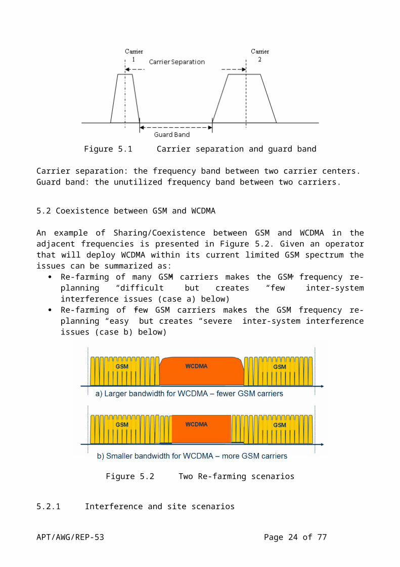
An example of Sharing/Coexistence between GSM and WCDMA in the adjacent frequencies is presented in Figure 5.2. Given an operator that will deploy WCDMA within its current limited GSM spectrum the issues can be summarized as:
Re-farming of many GSM carriers makes the GSM frequency re-planning “difficult” but creates “few” inter-system interference issues (case a) below)
Re-farming of few GSM carriers makes the GSM frequency re-planning “easy” but creates “severe” inter-system interference issues (case b) below)
Figure 5.2 Two Re-farming scenarios
5.2.1 Interference and site scenarios
Due to the imperfectness of the transmitter and/or receiver we may list some interference scenarios on how GSM and WCDMA interfere with each other.
APT/AWG/REP-53 Page 19 of 55
Figure 5.3 What and where the potential problems are
As Figure 5.3 is illustrating there are four important interference cases GSM downlink interfering with the WCDMA downlink WCDMA downlink interfering with the GSM downlink GSM uplink interfering with the WCDMA uplink WCDMA uplink interfering with the GSM uplink
In addition there are two site scenarios to consider: Coordinated sites i.e. the WCDMA and GSM antennas are co-located Un-coordinated sites i.e. there is no site sharing
5.2.2 WCDMA DL capacity loss due to GSM
The WCDMA DL capacity loss is controlled by the WCDMA terminal channel selectivity requiring at least at 2.8 MHz separation.
It is therefore difficult to make a prediction about performance if the carrier separation is decreased. However, regardless of the terminal performance, at a channel separation of 2.2-2.3 MHz the channel leakage increases dramatically and would make it very difficult indeed to operate with this kind of channel separation.
However, if the GSM channel power is sufficiently controlled and the traffic load is small it is possible to operate at a tolerable impact on the DL capacity.
One way of achieving this is to make sure that the GSM channels that overlap the WCDMA carrier (have spacing smaller than 2.6 MHz) are used in an low traffic sub-cell layer and aggressive BTS power control is used (and hence the impact on the DL WCDMA capacity also minimized).
5.2.3 WCDMA UL capacity loss due to GSM
APT/AWG/REP-53 Page 20 of 55
The WCDMA UL capacity loss is assumed to be controlled by the GSM terminal channel leakage. The GSM channel leakage behaves acceptable until 2.2-2.3 MHz carrier spacing, below which it becomes very difficult to operate.
Note that GSM terminals have a limited dynamic range for power control and at some small path loss they simply do not down regulate anymore. This implies that a single GSM terminal can cause severe WCDMA UL noise rise and corresponding severe degradation in coverage.
The remedy here is to make sure that the load on overlapping carriers (any carrier with a channel separation to the WCDMA carrier lower then say 2.4 MHz) must be very low indeed.
Another remedy is to avoid using these GSM carriers close to the base station.
5.2.4 GSM UL capacity loss due to WCDMA
The GSM UL performance is controlled by the WCDMA terminal channel leakage which is insignificant for a 2.8 MHz carrier separation.
From the specification data the critical point comes below 2.5-2.6 MHz separation where the channel leakage suddenly increases.
The GSM UL performance should degrade at channel separation below 2.5MHz, however given that WCDMA terminals have a much larger dynamic range in their power control it is a much less impacting effect than the one expected in WCDMA UL loss and the GSM UL performance on channels overlapping the WCDMA carrier is not significantly affected.
5.2.5 GSM DL capacity loss due to WCDMA
The GSM DL outage is insignificant for a 2.8 MHz carrier separation.
Assuming that the WCDMA base station controls the GSM DL performance at smaller channel separations a critical point appears to be at channel spacing around 2.5-2.6 MHz. Going below that seems to be very difficult.
5.2.6 Summary
The preferred scenario is to use coordinated GSM and WCDMA sites and the WCDMA carrier sandwiched in-between GSM carriers. The closest/overlapping GSM carriers should be TCH only (not a BCCH carrier), having the smallest traffic load possible and aggressive power control. This setup allows the use of a carrier spacing as low as 2.5MHz with low performance degradation both on WCDMA and GSM.
5.3 Coexistence of Various 2G/3G/4G Technologies in Band 5 and Band 8
Although initially the band 8 spectrum was used for GSM technology, at present in many countries this band is also being used for 3G (UMTS) and 4G (LTE) technologies. Similarly, the band 5 spectrum is initially used for CDMA2000 (CDMA) technology and now it is also being used for UMTS and LTE technologies, as a replacement. Because of the closeness between the 3GPP band 5
APT/AWG/REP-53 Page 21 of 55
downlink spectrum with the band 8 uplink spectrum, there is higher possibility for inter-band interference issues. Also due to multiple technologies being used with the band 5/8 spectrum, there is a possibility for intra-band interference issues happening within the band 5/8 spectrum. While collocated/coordinated deployments solve most of the intra-band interference issues, the inter-band interference issues would exist in both collocated/non-collocated deployment scenarios. The inter-band interference issues between the band 5 downlink and the band 8 uplink at 880/890 MHz boundary are very severe in nature and needs special attention to solve those interference issues.
With CDMA, UMTS & LTE technologies being used in the band 5 (assuming GSM850 possibility in Asia-Pacific region is very remote) and any of the GSM, UMTS & LTE technologies being used in the band 8 (as shown Figure 5.4), the following types of inter-band interference issues are observed between the band 5 downlink and the band 8 uplink at 880/890 MHz boundary:
- CDMA/UMTS/LTE850 base station transmission affecting the reception performance of GSM/UMTS/LTE900 base station (band 8 uplink is getting affected)
- GSM/UMTS/LTE900 mobile transmission affecting the reception performance of the CDMA/UMTS/LTE850 mobile (band 5 downlink is getting affected)
Figure 5.4 Inter-band interference issues between Band 5 and Band 8 systems
5.3.1 Inter-band and Intra-band Interference issues between Band 5 and Band 8
The inter-band interference issues are mainly either downlink-uplink or uplink-downlink type of interference issues and they are more severe in nature. This type of interference issues are difficult to deal with, because they would generally lead to performance degradation if not tackled properly. There are two types of inter-band interference issues and they are:
- Downlink Tx of the last the band 5 carrier (base station transmit) affecting the first band 8 carrier’s Uplink Rx (base station receive);
- First the band 8 carrier’s Uplink Tx (mobile transmit) affecting the last band 5 carrier’s Downlink Rx (mobile receive).
The two major interference issues with aggressor’s transmit affecting victim’s receive are:- OOBE (out-of-band emissions) of the aggressor signal entering as in-band interference that
can degrade the uplink performance at the victim’s receiverAPT/AWG/REP-53 Page 22 of 55
- High power adjacent channel signal of the aggressor acting as strong ACI (Adjacent channel interference) which may desensitize the victim’s receiver
While the OOBE type of interference can only be minimized at the source (at the aggressor’s transmitter) by improving the ACLR properties of the Aggressor through additional transmit filtering, the ACI type of interference can be minimized at the destination (at the victim’s receiver) by having better ACS properties of the Victim through additional receive filtering. To get the required additional ACLR/ACS characteristics, extra filtering is possible in the base stations. Whereas, for cost & space reasons it may not be possible to have such additional filters in mobiles.
Minimum Coupling Loss (MCL) based approach can be used to calculate the amount of isolation required to counter the effect of out-of-band emissions as well as the adjacent channel interference of the aggressor. The required isolation in base station to base station inter-band interference issues is achieved partly through spatial isolation from physical separation of antennas and remaining through special filters in Aggressor’s transmit and Victim’s receive paths.
In the inter-band interference issues case, there are two different problems, one with the band 5 base station transmit signal affecting the performance of the band 8 base station receive and the other with the band 8 mobile transmit affecting the performance of the band 5 mobile receive. In case of less than 90 dB of antenna isolation availability between the band 5 base station and the band 8 base station antennas, assuming always 10 to 15 dB (more than the standards required value) of additional ACLR and ACS would be available for base stations, then there is a need for additional 30+ dB of ACLR (through OOBE filtering) in the band 5 base station Tx path as well as additional 20+ dB of ACS (through ACI filtering) in the band 8 base stations’ Rx path.
In the case of the band 8 mobile Tx affecting the band 5 mobile Rx, interference free operation is not possible as the additional ACLR/ACS requirement is high and also it is not possible (cost & space point-of-view) to have additional filters in mobiles. However, the probability of mobile to mobile interference happening is very low, because the conditions that two close by the band 8 and band 5 mobiles simultaneously in active state and both in weak coverage state is very rare. Even though there is no additional filtering solution possible in mobiles (no mitigation solution available for the aggressor mobile Tx interference on victim mobile Rx), due to very low probability of such mobile-to-mobile interference happening (less than 2%), the victim downlink degradation possibility would also be very less.
Hence, to avoid inter-band interference issues, it is advisable (to the mobile wireless operators) to procure base station equipment along with such additional filtering in all 3G (UMTS850 and UMTS900) and 4G (LTE900) systems at the time of initial purchase itself. If not done during initial purchase, it is also possible to add these additional filters at a later stage.
As the new 3G/4G technologies gets introduced in to the band 8 spectrum as an overlay over the existing GSM technology deployments by carving out some spectrum, special care has to be taken by the operators on two fronts. One is choosing the right technology for the overlay and the other is the amount of spectrum to be carved out for the new technology. Also to be kept in mind is the knowhow on the possible intra-band interference issues and the ways & means to tackle such interference issues.
The intra-band interference issues can occur between two technologies operating in adjacent slots of the spectrum, especially when the base stations of these two technologies are deployed in an uncoordinated fashion. In the overlay with new technology scenario, it is going to be mostly a coordinated deployment and hence no intra-band interference issues. There is a slight advantage for UMTS900 overlay over the LTE900 overlay (in coordinated case), because of the additional guard
APT/AWG/REP-53 Page 23 of 55
band availability with a 5 MHz UMTS900 carrier, that allows two extra GSM (TCH) carriers in each side of the UMTS900 carrier (i.e., total of four GSM carriers), compared to no extra GSM carriers possible with a 5 MHz LTE900 carrier. In an un-coordinated (non-collocated) base station deployment (at the edge of operator’s spectrum) case, for minimal intra-band interference; 5 MHz of spectrum is required to be carved out for a UMTS900 carrier and 5.2 MHz of spectrum is required to be carved out for an LTE900 carrier.
5.3.2 Guard Band requirement in Inter-band case for cost-effective filtering
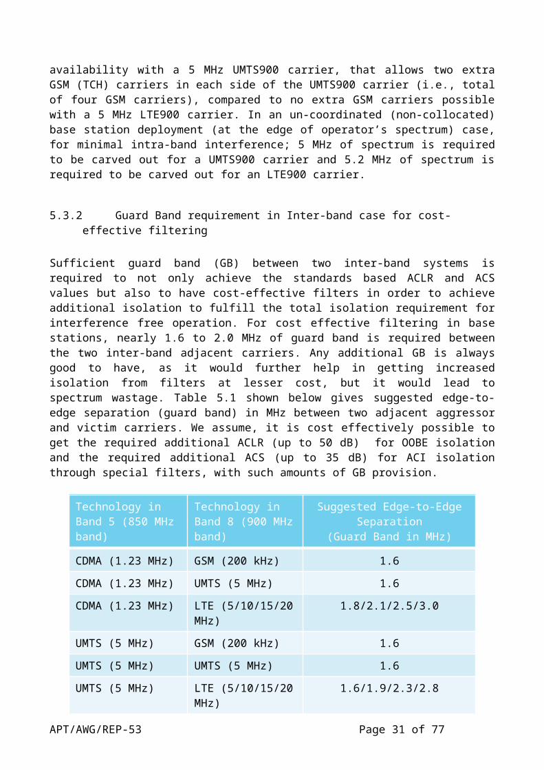
Sufficient guard band (GB) between two inter-band systems is required to not only achieve the standards based ACLR and ACS values but also to have cost-effective filters in order to achieve additional isolation to fulfill the total isolation requirement for interference free operation. For cost effective filtering in base stations, nearly 1.6 to 2.0 MHz of guard band is required between the two inter-band adjacent carriers. Any additional GB is always good to have, as it would further help in getting increased isolation from filters at lesser cost, but it would lead to spectrum wastage. Table 5.1 shown below gives suggested edge-to-edge separation (guard band) in MHz between two adjacent aggressor and victim carriers. We assume, it is cost effectively possible to get the required additional ACLR (up to 50 dB) for OOBE isolation and the required additional ACS (up to 35 dB) for ACI isolation through special filters, with such amounts of GB provision.
Technology in Band 5 (850 MHz band)
Technology in Band 8 (900 MHz band)
Suggested Edge-to-Edge Separation (Guard Band in MHz)
CDMA (1.23 MHz) GSM (200 kHz) 1.6
CDMA (1.23 MHz) UMTS (5 MHz) 1.6
CDMA (1.23 MHz) LTE (5/10/15/20 MHz) 1.8/2.1/2.5/3.0
UMTS (5 MHz) GSM (200 kHz) 1.6
UMTS (5 MHz) UMTS (5 MHz) 1.6
UMTS (5 MHz) LTE (5/10/15/20 MHz) 1.6/1.9/2.3/2.8
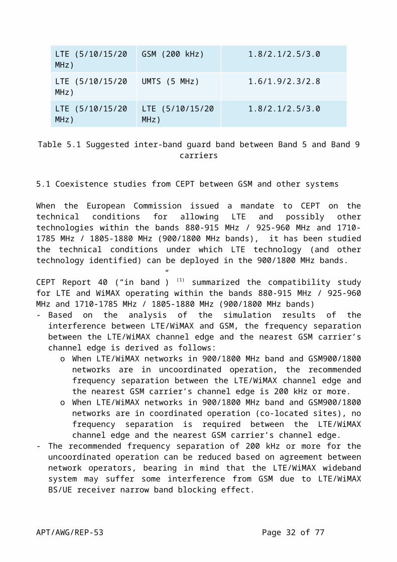
LTE (5/10/15/20 MHz) GSM (200 kHz) 1.8/2.1/2.5/3.0
LTE (5/10/15/20 MHz) UMTS (5 MHz) 1.6/1.9/2.3/2.8
LTE (5/10/15/20 MHz) LTE (5/10/15/20 MHz) 1.8/2.1/2.5/3.0
Table 5.1 Suggested inter-band guard band between Band 5 and Band 9 carriers
5.4 Coexistence studies from CEPT between GSM and other systems
When the European Commission issued a mandate to CEPT on the technical conditions for allowing LTE and possibly other technologies within the bands 880-915 MHz / 925-960 MHz and 1710-1785 MHz / 1805-1880 MHz (900/1800 MHz bands), it has been studied the technical conditions under which LTE technology (and other technology identified) can be deployed in the 900/1800 MHz bands.
APT/AWG/REP-53 Page 24 of 55

CEPT Report 40 (“in band”) (1) summarized the compatibility study for LTE and WiMAX operating within the bands 880-915 MHz / 925-960 MHz and 1710-1785 MHz / 1805-1880 MHz (900/1800 MHz bands)- Based on the analysis of the simulation results of the interference between LTE/WiMAX and
GSM, the frequency separation between the LTE/WiMAX channel edge and the nearest GSM carrier’s channel edge is derived as follows:
o When LTE/WiMAX networks in 900/1800 MHz band and GSM900/1800 networks are in uncoordinated operation, the recommended frequency separation between the LTE/WiMAX channel edge and the nearest GSM carrier’s channel edge is 200 kHz or more.
o When LTE/WiMAX networks in 900/1800 MHz band and GSM900/1800 networks are in coordinated operation (co-located sites), no frequency separation is required between the LTE/WiMAX channel edge and the nearest GSM carrier’s channel edge.
- The recommended frequency separation of 200 kHz or more for the uncoordinated operation can be reduced based on agreement between network operators, bearing in mind that the LTE/WiMAX wideband system may suffer some interference from GSM due to LTE/WiMAX BS/UE receiver narrow band blocking effect.
CEPT Report 41 (“adjacent band”) (2) summarized compatibility study between LTE and WiMAX operating within the bands 880-915 MHz / 925-960 MHz and 1710-1785 MHz / 1805-1880 MHz (900/1800 MHz bands) and systems operating in adjacent bands
CEPT Report 42 (3) summarized the investigation on compatibility between UMTS and adjacent band systems above 960MHz. The Report focuses on the compatibility between UMTS 900 on the one hand, and the aeronautical systems (existing: DME and future: L-DACS) in the band 960-1215/1164 MHz.
6 General migration process
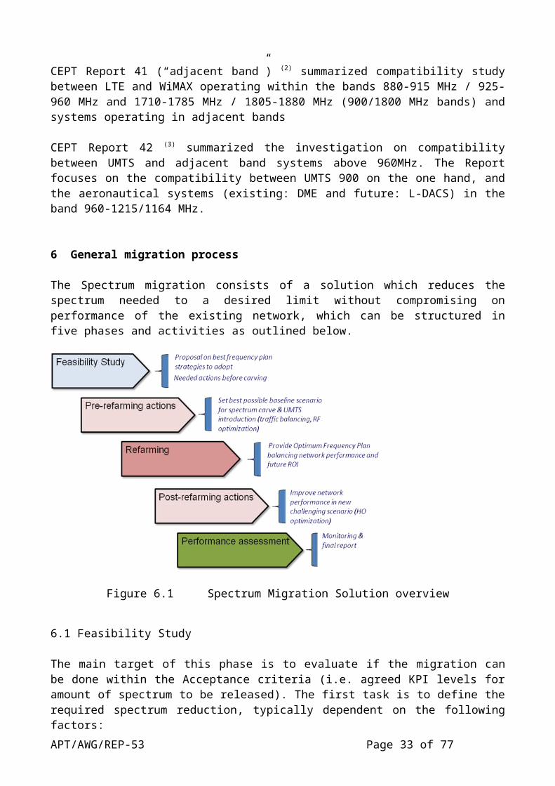
The Spectrum migration consists of a solution which reduces the spectrum needed to a desired limit without compromising on performance of the existing network, which can be structured in five phases and activities as outlined below.
APT/AWG/REP-53 Page 25 of 55
Figure 6.1 Spectrum Migration Solution overview
6.1 Feasibility Study
The main target of this phase is to evaluate if the migration can be done within the Acceptance criteria (i.e. agreed KPI levels for amount of spectrum to be released). The first task is to define the required spectrum reduction, typically dependent on the following factors:
- Operator restrictions- Maturity of the network- Expected traffic growth- Network evolution
6.2 Pre Re-farming actions
In this phase, using output from the feasibility study, a complete set of actions will be proposed in order to establish the best baseline scenario for the implementation of a new frequency plan after the spectrum carving. These actions are typically includes RF Optimization and RRM Optimization.
There are several functions which can be used to aid in the achievement of the objectives (capacity, interference and traffic management). These functions will reduce the interference levels or improve the network’s ability to cope with the increased interference.
6.3 Frequency Plan elaboration & implementation
In this phase the final frequency will be implemented guided by the strategies defined in the previous phase. This phase includes the following parts:
- Frequency Plan- Updated Neighbor List- Fall-back plan
Fall back to the previous frequency plan A fast reactive process to identify & troubleshoot the worst performing sectors
6.4 Post Re-farming actions
A second round of optimization actions may be proposed after the implementation of the Re-farmed frequency plan. In order to understand the real scope of this phase, a Performance Analysis must be carried for two main reasons:
Ensure no severe degradation is present post-Re-farming. If this is the case, then a fall-back plan will be auctioned.
Acknowledge the necessary actions to be carried out in order to meet the agreed Acceptance criteria.
6.5 Performance Assessment
After Implementation, the network will be monitored mainly through the OSS-based tool. Other tools may be also utilized for specific monitoring tasks.
7 Some case study
APT/AWG/REP-53 Page 26 of 55
Operators in Europe and Asia are re-farming parts of their 2G spectrum to allow new technology introduction. The general trend has been to re-use 900MHz for 3G and 1800MHz for LTE. The driver for 3G in 900MHz is to improve coverage since low frequency spectrum has better coverage characteristics compared with the higher frequencies thereby allowing both deeper and broader coverage. The device eco-system for 900MHz is also very strong.
In many markets, the motivation for deploying LTE in their existing 1800MHz band is a combination of capacity relief and to demonstrate market leadership by launching LTE services before new spectrum, such as 2600MHz, is available. The device eco-system for L1800 is also very strong – particularly at the high end of the market.
The main considerations for re-farming are spectrum efficiency, traffic management and customer migration.
Spectrum efficiency
For re-farming, operators have had to optimize their network to carry the same traffic but in less spectrum by using techniques such as Fractional Load Planning. The spectrum that is made available is then either used for the new technology or used to carry more GSM traffic (see traffic management below).
By optimizing the cell plan and through the use of channel management and interference limiting software features, operators can minimize the frequency channels required for their BCCH plan as well as being able to carry more traffic on their existing spectrum by leveraging the benefits that were built into the GSM standard from the very beginning for example frequency hopping which exploits the error correction mechanisms built into GSM channel coding.
Traffic Management
Since many operators have GSM on both 900MHz and 1800MHz, traffic management techniques can be used to move traffic between the bands. One approach used by operators is to reduce the number of transceivers used in the 900MHz band to make room for a 3G carrier. The resulting drop in capacity in the 900MHz band is then compensated for by increasing the number of transceivers in the 1800MHz band due to the improvement of spectral efficiency (see above). Care is needed with this approach to ensure that the coverage limitations of 1800MHz are considered. This approach is also valid for moving traffic off 1800MHz to 900MHz
Customer Migration
With good 3G coverage, 2G load naturally decreases as customers migrate. In these cases, the drop in 2G load has enabled operators to free up spectrum for new technologies. The Telstra case study is a good example of this.
7.1 General scenarios
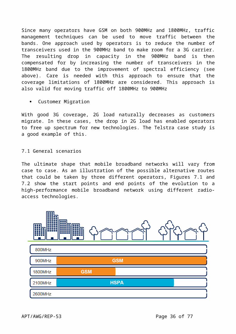
The ultimate shape that mobile broadband networks will vary from case to case. As an illustration of the possible alternative routes that could be taken by three different operators, Figures 7.1 and 7.2 show the start points and end points of the evolution to a high-performance mobile broadband network using different radio-access technologies.
APT/AWG/REP-53 Page 27 of 55
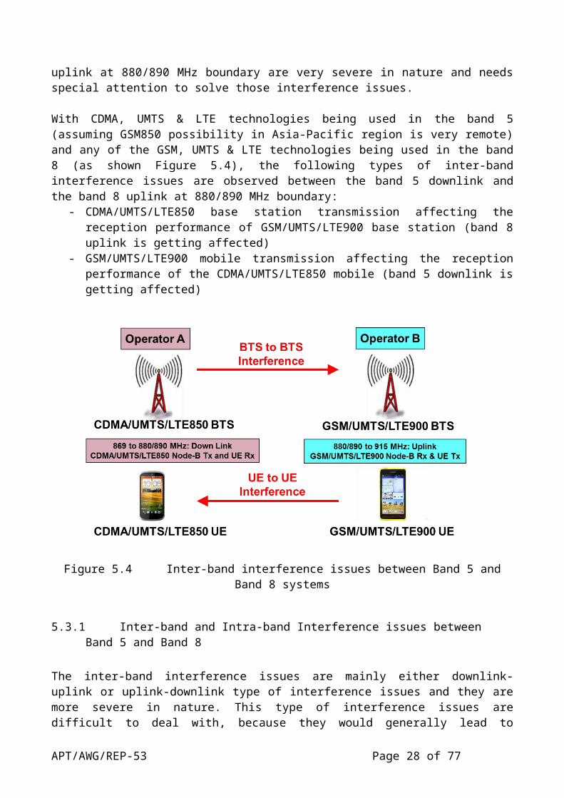
Figure 7.1 Starting frequency band allocation and technology deployment for the operator
Figure 7.2 Evolved frequency band allocation and deployment for the operator
Typical European frequencies are used to illustrate the strategies for this evolution.Scenario 1: This operator has no early access to either 2600MHz or 800MHz spectrum for LTE. Here, the first step is to re-farm the 900MHz spectrum to HSPA in order to boost 3G coverage and capacity, especially in rural areas. As GSM traffic diminishes as a result of the greater HSPA capacity, the operator can re-farm the 1800MHz spectrum either for LTE or HSPA to provide high-performance mobile broadband in urban and suburban areas. The technology choice will depend on the operator’s market position, the current and projected device fleet, the ability to serve mass-market volumes of HSPA smartphones in existing 3GPP bands, and the availability of other bands for LTE. In this scenario, the operator is able to roll out LTE in other bands as it becomes available.Scenario 2: This operator has already deployed WCDMA/HSPA in the 900MHz, as well as in the 2100MHz band. The total spectrum in these deployments is sufficient to cater for mass HSPA smartphone uptake. By driving the uptake of 3G-capable devices that use 3G access for voice and
APT/AWG/REP-53 Page 28 of 55
data, and rolling out GSM efficiency improvements, GSM traffic can be served within the 900MHz spectrum. This frees up the 1800MHz spectrum for LTE deployment.
Scenario 3: This operator has early access to 2600MHz spectrum for LTE, as well as the option for rolling out LTE in the Digital Dividend 800MHz band (made available following the shutdown of Europe’s analog TV networks). The operator’s first step is to re-farm 900MHz spectrum to WCDMA/HSPA to provide wider and deeper 3G coverage and capacity, especially for rural and indoor areas. Increasing use of WCDMA/HSPA in the wide area gradually reduces load on the GSM/EDGE network.
In addition, the operator deploys LTE in the 2600MHz band in urban hotspots to provide a high-speed mobile-broadband service to complement the HSPA access. After this, the operator rolls out LTE in the 800MHz band to provide high-performance broadband in the wide area, including rural areas.
Ultimately, when GSM traffic has diminished significantly, the operator can re-farm the 1800MHz spectrum for LTE as well to provide a further capacity and boost coverage. Alternatively, if the need for additional HSPA capacity is more pressing at this time, the operator has the option of deploying HSPA in the 1800MHz spectrum.
7.2 Telstra LTE1800 Introduction
One of Telstra’s key strategies following the 2006 launch of its Next G WCDMA network was a concerted effort to move 2G users to the new network. Many factors lay behind this strategy, including network rationalization, coherent branding and operational efficiency. To provide incentives for users to move to 3G, Telstra relied on a variety of options, such as free handset upgrades and attractive “no premium” pricing plans. As users moved to more advanced technology, they became more likely to adopt new services. But perhaps the most significant outcome was Telstra’s ability to “empty” its 2G network and re-farm the 1800MHz spectrum to launch Australia’s first LTE network in September 2011.
Since the Next G network launch, the volume of traffic in Telstra’s mobile network has doubled every year. In late 2010, through a capacity modeling tool, the operator forecast that the Next G network capacity would run out before the new 700MHz spectrum – primed for LTE – became available. So something had to be done – and fast.
Spectrum re-farming was not new to Telstra. It had already successfully introduced WCDMA on re-farmed 850MHz and built a healthy ecosystem in the process. In pioneering a global 1800MHz LTE ecosystem, Telstra took the same approach, playing an active role by working in conjunction with infrastructure suppliers, device and chipset manufacturers and industry bodies. Today, 1800MHz has become the most popular LTE band worldwide.
When Telstra launched the nation’s first LTE network, it was seen by industry observers as a six month head start on competitors that could consolidate the company’s already dominant position. The launch was as much a result of Telstra’s engineering strategy as of its business strategy.
8 Conclusion
This Report studies the deployment and evolution of IMT networks, especially network evolution of 2G bands for IMT. 2G networks, GSM, are deployed popularly on 900 MHz and 1800 MHz bands for years in global scale. IMT technologies such as HSPA and LTE are available in those bands, in both network equipment and terminals aspect. Re-farming is a strategy where telecom operators APT/AWG/REP-53 Page 29 of 55
reuse their frequency resources to introduce new radio communication technologies to improve the spectral efficiency and data throughput.
The spectrum migration consists of a solution which reduces the spectrum needed to a desired limit without compromising on performance of the existing network, which can be structured in five phases and activities. With suitable migration strategy, there are no significant changes in key performance indicators after this re-farm. Different studies also show that HSPA/LTE can be deployed in the current GSM band, and the preferred scenario is to use coordinated 2G and IMT sites.
Operators around the world are re-farming parts of their 2G spectrum to allow new technology introduction. The general trend has been to re-use 900MHz for 3G and 1800MHz for LTE. The driver for 3G in 900MHz is to improve coverage since low frequency spectrum has better coverage characteristics compared with the higher frequencies thereby allowing both deeper and broader coverage. In many markets, the motivation for deploying LTE in their existing 1800MHz band is a combination of capacity relief and to demonstrate market leadership by launching LTE services before new spectrum, such as 2600MHz, is available.
9 Reference
(1) CEPT Report 40, Compatibility study for LTE and WiMAX operating within the bands 880-915 MHz / 925-960 MHz and 1710-1785 MHz / 1805-1880 MHz (900/1800 MHz bands)
(2) CEPT Report 41, Compatibility between LTE and WiMAX operating within the bands 880-915 MHz / 925-960 MHz and 1710-1785 MHz / 1805-1880 MHz (900/1800 MHz bands) and systems operating in adjacent bands
(3) CEPT Report 42, Compatibility between UMTS and existing and planned aeronautical systems above 960 MHz
(4) http://www.gsacom.com/gambod
(5) APT/AWG/REP-15 (Rev.1), APT Report on "Information of Mobile Operator's Frequencies, Technologies and License Durations in Asia Pacific Countries"
(6) ECC Report 82: Compatibility Study For UMTS Operating Within The GSM 900 And GSM 1800 Frequency Bands
10
APT/AWG/REP-53 Page 30 of 55
ANNEX
1 Interference issues around Band 5 and Band 8 Spectrum
Because of the closeness between the band 5 downlink spectrum with band 8 uplink spectrum, there is higher possibility for inter-band interference issues. Also due to multiple technologies being used in band 5/8 spectrum, there is a possibility for intra-band interference issues happening within band 5/8 spectrum.
With CDMA, UMTS & LTE technologies being used in band 5 (assuming GSM850 possibility in Asia-Pacific region is very remote) and any of the GSM, UMTS & LTE technologies being used in band 8, the following two types of inter-band interference issues are observed between the band 5 downlink and the band 8 uplink:
CDMA/UMTS/LTE850 base station transmission affecting the reception performance of GSM/UMTS/LTE900 base station (band 8 uplink is getting affected)
GSM/UMTS/LTE900 mobile transmission affecting the reception performance of the CDMA/UMTS/LTE850 mobile (band 5 downlink is getting affected)
2 Inter-band Interference issues between Band 5 and Band 8
The inter-band interference issues are mainly either downlink-uplink or uplink-downlink type of interference issues and they are more severe in nature. This type of interference issues are difficult to deal with, because they would generally lead to performance degradation if not tackled properly. There are two types of inter-band interference issues and they are:
- Downlink Tx of the last band 5 carrier (base station transmit) affecting the first band 8 carrier’s Uplink Rx (base station receive)
- First band 8 carrier’s Uplink Tx (mobile transmit) affecting the last band 5 carrier’s Downlink Rx (mobile receive)
The two major interference issues with aggressor’s transmit affecting victim’s receive are:- OOBE (out-of-band emissions) of the aggressor signal entering as in-band interference that
can degrade the uplink performance at the victim’s receiver- High power adjacent channel signal of the aggressor acting as strong ACI (Adjacent channel
interference) which may desensitize the victim’s receiver
While the OOBE type of interference can only be minimized at the source (at the aggressor’s transmitter) by improving the ACLR properties of the Aggressor through additional transmit filtering, the ACI type of interference can be minimized at the destination (at the victim’s receiver) by having better ACS properties of the Victim through additional receive filtering. To get the required additional ACLR/ACS characteristics, extra filtering is possible in the base stations. Whereas, for cost & space reasons it may not be possible to have such additional filters in mobiles.
Minimum Coupling Loss (MCL) based approach can be used to calculate the amount of isolation required to counter the effect of out-of-band emissions as well as the adjacent channel interference of the aggressor. The required isolation in base station to base station inter-band interference issues is achieved partly through spatial isolation from physical separation of antennas and remaining through special filters in Aggressor’s transmit and Victim’s receive paths.
To get 1.6 MHz of GB, the right hand side (RHS) edge of last CDMA/UMTS/LTE850 downlink carrier has to end at 888.4 MHz (with 890 MHz boundary) or at 878.4 MHz (with 880 MHz boundary) and the left hand side (LHS) edge of the GSM/UMTS/LTE900 uplink carrier has to start
APT/AWG/REP-53 Page 31 of 55
at 890 MHz or 880 MHz. With 10/15/20 MHz LTE carriers, as the passband of the filters also gets increased, higher amount GB (> 1.6 MHz) is required to get cost effective filtering.
In order to perform MCL based inter-band interference analysis, the ACLR value of the Aggressor, the ACS value and the tolerable in-band & adjacent carrier interference levels for the Victim are to be ascertained. Table A.1 provides a list of the parameters/characteristics for both the aggressor and victim systems in BTS to BTS interference scenario, and their associated values to be used in the isolation calculations, considering the availability of 1.6 MHz of guard band. The parameter values are extrapolated for the guard band availability and are based on 3GPP standards specifications.
Aggressor(850 MHz DL Tx)
ACLR (dB)
Victim(900 MHz UL Rx)
Tolerable In-band Interference (dBm) (RS- 6 dB)
ACS (dB)
Tolerable ACI(dBm) (RS + ACS)
CDMA850 BTS
55 GSM900 BTS -110 80 -24
UMTS850 Node-B
50 UMTS900 Node-B
-113 55 -52
LTE850 eNode-B
48 LTE900 eNode-B
-107.5 50 -51.5
Table A.1: Parameters used in BTS850 DL Tx vs. BTS900 UL Rx Interference Analysis
Similarly, a list of the parameters/characteristics for both the aggressor and victim systems in UE to UE interference scenario, and their associated values to be used in the isolation calculations, for 1.6 MHz of guard band is given in Table A.2 shown below. The parameter values are extrapolated for the guard band availability and are based on 3GPP standards specifications.
Aggressor(900 MHz UL Tx)
ACLR (dB)
Victim(850 MHz DL Rx)
Tolerable In-band Interference (dBm) (RS)
ACS (dB)
Tolerable ACI(dBm)(RS+6dB+ACS)
GSM900 MS 75 C2K850 MS -106 50 -50
UMTS900 UE
38 UMTS850 UE -101 38 -57
LTE900 UE 33 LTE850 UE -97 35 -56Table A.2: Parameters used in UE900 UL Tx vs. UE850 DL Rx Interference Analysis
There are nine inter-band interference issues that can arise between band 5 and band 8 @ 880/890 MHz boundary and they are:
1. CDMA850 system in Band 5 while GSM900 system in Band 82. CDMA850 system in Band 5 while UMTS900 system in Band 83. CDMA850 system in Band 5 while LTE900 system in Band 84. UMTS850 system in Band 5 while GSM900 system in Band 85. UMTS850 system in Band 5 while UMTS900 system in Band 86. UMTS850 system in Band 5 while LTE900 system in Band 8
APT/AWG/REP-53 Page 32 of 55
7. LTE850 system in Band 5 while GSM900 system in Band 88. LTE850 system in Band 5 while UMTS900 system in Band 89. LTE850 system in Band 5 while LTE900 system in Band 8
In the following sub-sections 2.1 to 2.9, the Minimum Coupling Loss (MCL) based analysis is done to check the inter-band interference issues between band 5 systems and band 8 systems. We would start with CDMA system in band 5 verses GSM systems in band 8, followed by all the other eight above mentioned scenarios. In all the nine possible inter-band interference issues, the balance isolation to be achieved through additional filters is calculated assuming that it is possible to ensure (at any time) a minimum antenna isolation of 60 dB between Aggressor and Victim base station antennas.
2.1 Inter-band Interference issues between CDMA850 and GSM900 systems
When CDMA system is used in band 5 and GSM system is used in band 8 near the 880/890 MHz boundary, there can be two types of potential interference issues and they are:
- CDMA850 base station transmit affecting GSM900 base station receive- GSM900 mobile transmit affecting CDMA850 mobile receive
Based on the values provided in Table A.1, it is possible to ascertain the signal levels of the CDMA BTS Tx and its OOBE (Out-of-band emission) at various positions within CDMA BTS and also at the Victim (GSM) BTS. See Figure A.1 below for more details.
Figure A.1: Signal level diagram for CDMA850 BTS Tx vs. GSM900 BTS Rx
With just 30 dB of additional ACLR (in CDMA BTS Tx path) and just 7 dB of additional ACS (in GSM BTS Rx path) and at least with a minimum of 60 dB of antenna isolation, it is possible to have BTS-to-BTS inter-band interference free operation at the 890 MHz boundary.
The other inter-band interference issue between CDMA850 and the GSM900 is the mobile-to-mobile interference issue. For cost and space reasons, it is not possible to have special filters in the mobiles
APT/AWG/REP-53 Page 33 of 55
and hence, it may not be possible to meet the OOBE and ACI isolation requirement in this case, But, the good thing is the mobile-to-mobile interference issues (i.e., Band 8 UE Tx affecting band 5 UE Rx) happen only when all the following conditions are fully met, which is going to be very rare:
- Both band 8 and band 5 mobiles are in active mode while they are very close to each other- Both close-by band 8 and band 5 mobiles working in their extreme edge carriers (between the
850 MHz last carrier and 900 MHz first carrier)- Both mobiles operating in their cell edge signal conditions (i.e., Band 8 mobile transmitting at
its peak and band 5 mobile receiving very low signal)
Hence, the overall chance for such mobile-to-mobile interference happening is going to be very remote and therefore, shortage in meeting the OOBE and ACI isolation requirement in this case may not be a problematic issue. Still, there is little probability of meeting all those three conditions in thickly populated areas such as malls, railway stations, airports, convention centers etc., and hence there is some probability (2 to 5 %) for the CDMA850 downlink performance degradation.
For completeness sake let us carry out the inter-band interference analysis for the GSM mobile Tx affecting CDMA850 mobile Rx case. Figure A.2 provides signal levels (based on Table A.2) for the mobile-to-mobile inter-band interference analysis details.
Figure A.2: Signal level diagram for GSM900 MS Tx vs. CDMA850 MS Rx
Hence, 15 dB of additional ACLR (in GSM900 MS Tx path) and 29 dB of additional ACS (in CDMA850 MS Rx path) is required when there is a minimum of 40 dB of antenna isolation between mobiles. As it is not possible to have special filters in mobiles, no mitigation solution possible for mobile-to-mobile inter-band interference issues. Only good thing is that occurrence of such mobile-to-mobile inter-band interference issues is very rare.
2.2 Inter-band Interference issues between CDMA850 and UMTS900 systems
When CDMA system is used in band 5 and UMTS system is used in band 8 near the 880/890 MHz boundary, there can be two types of potential interference issues and they are:
- CDMA850 base station transmit affecting UMTS900 base station receive- UMTS900 mobile transmit affecting CDMA850 mobile receive
Figure A.3 provides the signal levels of the CDMA BTS Tx and its OOBE (Out-of-band emission) at various positions within CDMA BTS and also at the Victim (UMTS) Node-B. From the signal levels APT/AWG/REP-53 Page 34 of 55
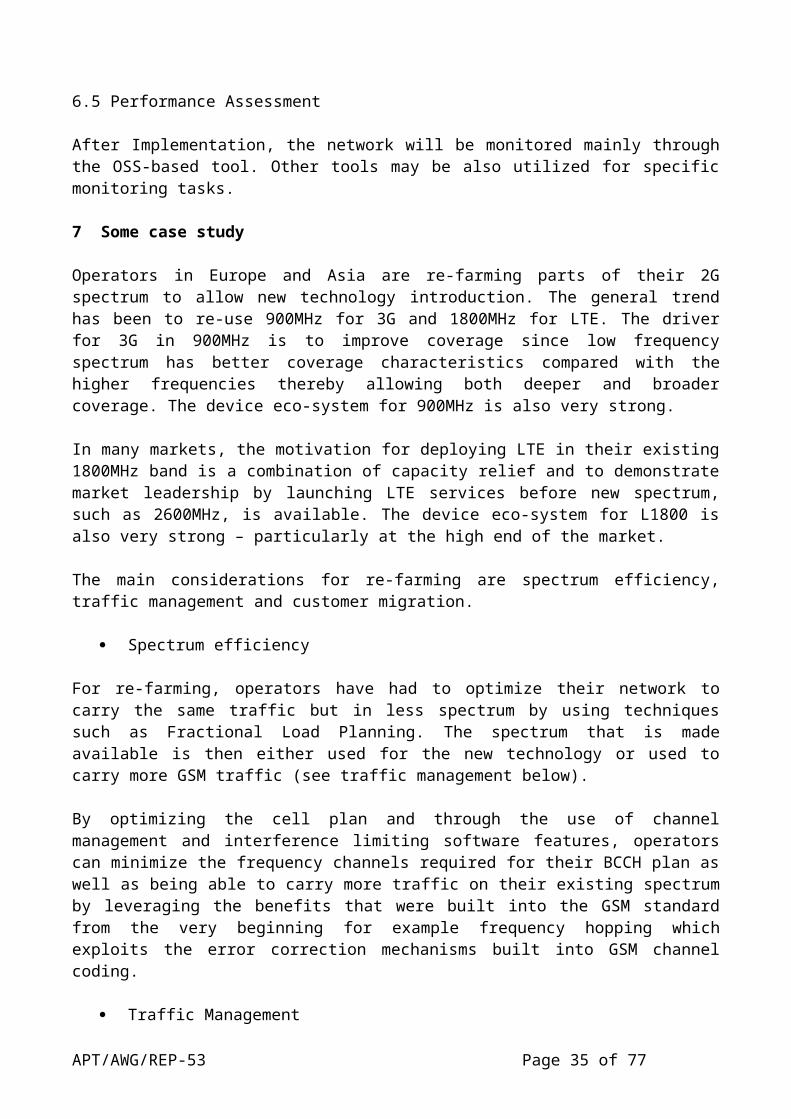
diagram shown below, it is observed that an additional ACLR (in CDMA BTS Tx path) of 41 dB and an additional ACS of 35 dB (in UMTS900 Node-B Rx path) along with at least a minimum of 60 dB of antenna isolation is required to mitigate the base station-to-base station inter-band interference issues at the 890 MHz boundary. See this below signal levels diagram for details.
Figure A.3: Signal level diagram for CDMA850 BTS Tx vs. UMTS900 BTS Rx
The other inter-band interference issue is between the UMTS900 and CDMA850 mobiles. The Inter-band interference analysis for the UMTS900 UE Tx affecting CDMA850 MS Rx case is being depicted in Figure A.4 below.
Figure A.4: Signal level diagram for UMTS900 UE Tx vs. CDMA850 MS Rx
For mobile-to-mobile interference free operation, about 33 dB of additional ACLR (in GSM900 MS Tx path) and 15 dB of additional ACS (in CDMA850 MS Rx path) required along with a minimum
APT/AWG/REP-53 Page 35 of 55
of 40 dB of antenna isolation between mobiles. As it is not possible to have special filters in mobiles, no mitigation solution possible for mobile-to-mobile inter-band interference issues. Only good thing is that occurrence of such mobile-to-mobile inter-band interference issues is very rare, leading to very low probability (around 2%) of CDMA850 downlink performance degradation.
2.3 Inter-band Interference Issues between CDMA850 and LTE900 Systems
When CDMA technology is being used in band 5 and LTE technology is used in band 8 near the 880/890 MHz boundary, there can be two types of potential interference issues and they are:
- CDMA850 base station transmit affecting LTE900 base station receive- LTE900 mobile transmit affecting CDMA850 mobile receive
Figure A.5 shown below provides the signal and the interference levels at each point within the entire system considered for the coexistence check interference analysis of CDMA850 BTS Tx affecting LTE900 eNode-B Rx case, for calculating the OOBE and ACI isolation requirements.
Figure A.5: Signal level diagram for CDMA850 BTS vs. LTE900 eNode-B case
Tolerable interference level of the LTE900 eNode-B receiver is -107.5 dBm/5 MHz and hence for coexistence of these systems without causing any significant interference issues, the CDMA850 BTS OOBE has to be suppressed to -107.5 dBm/5 MHz at the LTE900 receiver. From the signal levels diagram, assuming a minimum of 60 dB isolation/coupling loss available from the antenna separation (between CDMA850 and LTE900 base station antennas), for base station-to-base station interference free operation still 35.5 dB of OOBE suppression is required at the CDMA850 transmitter (-12 dBm - 60dB – 35.5dB = -107.5 dBm). In general, base station vendors do come up with 10 to 15 dB better ACLR than the specifications. Hence, there is a need for special RF filtering requirement in CDMA850 BTSs for additional ACLR of 25 dB.
Typical max. CDMA850 BTS Tx signal of 43 dBm would be seen as adjacent channel interference (1.6 MHz away from edge) by the LTE900 eNode-B receiver. With antenna isolation of 60 dB between CDMA850 BTS and LTE900 eNode-B antennas, the estimated CDMA850 BTS Tx power at LTE900 eNode-B duplexer in is -17 dBm/5 MHz. With additional ACI isolation through RF filtering in LTE900 eNode-B receive filter/duplexer to the tune of 35 dB, the ACI signal of the APT/AWG/REP-53 Page 36 of 55
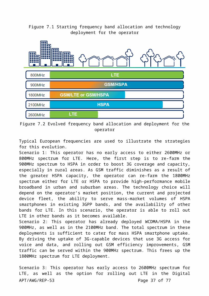
adjacent band becomes -52 dBm at LTE900 eNode-B receiver. The ACI tolerance level of LTE900 eNode-B receiver is -51.5 dBm, therefore the ACI check is passed Rx with 35 dB of additional filtering at the LTE900 eNode-B Rx path.
Similar analysis can be performed for the scenario where the LTE900 uplink transmission (UE Transmit) affects the CDMA850 downlink reception (MS receive). Figure A.6 provides signal and interference levels at each point of the LTE900 UE Tx affecting CDMA850 MS Rx case checking the coexistence interference analysis for calculating the OOBE and ACI isolation requirements.
Figure A.6: Signal levels diagram for LTE900 UE vs. CDMA850 MS case
The max. LTE900 UE Tx OOBE for 1.6 MHz away has to be 33 dB down (as per 3GPP TS 36.101). With typical LTE900 UE max. Tx Power of 20 dBm, the OOBE at the LTE900 UE Tx PA is, 20 -33 = -13 dBm /5 MHz. Considering 5 dB of OOBE isolation is available through LTE900 UE duplexer on Tx path for 1.6 MHz of GB, and also considering a minimum antenna isolation of 40 dB between LTE900 UE and CDMA850 MS with 1m physical separation, the LTE900 UE Tx OOBE at CDMA850 MS duplexer In is -13 -5 -40 = -58 dBm/5 MHz. The tolerable in-band interference at the CDMA850 MS has to be -106 dBm and hence the OOBE interference from LTE900 UE Tx of -58 dBm is much higher than the tolerable level (shortage by 48 dB). It would not be possible to have any special (extra) filtering in mobiles to achieve this 48 dB shortage and therefore OOBE check in mobile-to-mobile interference case has failed.
Though the max. LTE900 UE Tx signal is 23 dBm, the typical max. would be 20 dBm and that would become an ACI (with 1.6 MHz of GB) to the CDMA850 MS receiver. With antenna isolation of 40 dB between LTE900 UE and CDMA850 MS, estimated LTE900 UE Tx power at CDMA850 MS duplexer in is -20 dBm. Assuming duplexer at CDMA850 MS gives additional 5 dB isolation for ACI signal of LTE900, the LTE900 UE Tx power is down to -25 dBm before entering the CDMA850 MS receiver. ACI tolerance level of CDMA850 MS receiver is - 50 dBm, therefore the ACI check failed (shortage of 25 dB ACS). Hence, due to ACI interference problem there can be performance degradation to CDMA850 downlink.
However, the probability of occurrence of LTE900 UE Tx interference to CDMA850 MS Rx is very rare. Therefore, shortage in meeting the OOBE and ACI isolation requirement in UE to UE
APT/AWG/REP-53 Page 37 of 55
interference case may be of less concern. Still, there is some probability of such interference in thickly populated areas such as malls, railway stations, airports, convention centers etc., and hence there is a 2 to 5 % chance for the CDMA850 downlink performance degradation.
2.4 Inter-band Interference issues between UMTS850 and GSM900 systems:
When UMTS is being used in band 5 and GSM is being used in band 8 near the 880/890 MHz boundary, there can be two types of potential interference issues and they are:
- UMTS850 base station transmit affecting GSM900 base station receive- GSM900 mobile transmit affecting UMTS850 mobile receive
Figure A.7 shown below provides the signal and interference levels at each point considered for the coexistence check interference analysis of UMTS850 Node-B transmit affecting GSM900 base station receive case for calculating the OOBE and ACI isolation requirements.
Figure A.7: Signal levels diagram for UMTS850 Node-B vs. GSM900 BTS case
The max. UMTS850 BTS Tx OOBE at 1.6 MHz (of GB) away would be -7 dBm/3.84 MHz (as per 3GPP TS 25.104) i.e., -20 dBm/200kHz. Minimum antenna isolation of 60 dB between UMTS850 Node-B and GSM900 BTS antennas can be ensured through coordinated antenna installation. Hence, UMTS850 Node-B Tx OOBE at GSM900 BTS antenna-in is -20 - 60 = -80 dBm/200kHz. As the OOBE interference from UMTS850 BTS Tx at GSM BTS receiver has to be on par or below the tolerable interference level of -110 dBm (RS - 6 dB), the additional OOBE isolation required through special filters in UMTS850 Node-B Tx path is 30 dB (-80 - (-110)). Hence, the interference problem to GSM900 BTS receiver from the OOBE of the UMTS850 BTS Tx can be avoided by having 30 dB of additional ACLR in UMTS850 Node-B Tx path.
The typical max. value for UMTS850 Node-B Tx signal is 43 dBm and this would become an ACI to the GSM900 BTS receiver. Assuming minimum antenna isolation availability of 60 dB between UMTS850 BTS Tx and GSM900 BTS receiver (through coordinated deployment and certain physical separation distance between UMTS850 Node-B Tx and GSM900 BTS Rx antennas), the estimated UMTS850 Node-B Tx power at GSM900 BTS receiver In is 43 -60 -13 (i.e., bandwidth correction factor 10*log 3840/200) = -30 dBm/200kHz. As the ACI tolerance level of GSM900 BTS APT/AWG/REP-53 Page 38 of 55
receiver is -24 dBm (ACS of GSM BTS is 80 dB), therefore the ACI check is passed. Hence, no interference problem to GSM900 BTS Rx from the adjacent channel interference of UMTS850 Node-B Tx.
Similar to the above BTS-to-BTS interference analysis, it is also required to perform interference analysis for the GSM900 uplink transmission (MS Transmit) affecting the UMTS850 downlink reception (UE receive). Figure A.8 provides signal and interference levels at each point of the GSM900 MS Tx affecting UMTS850 UE Rx case checking the coexistence interference analysis to calculate the OOBE and ACI isolation requirements.
Figure A.8: Signal levels diagram for GSM900 MS vs. UMTS850 UE case
The max. GSM900 MS Tx OOBE (1.6 MHz away from edge) would be 75 dB down (as per CEPT ECC report 40 & 82). With typical GSM900 MS max. Tx Power = 24 dBm, the OOBE at the GSM900 MS Tx PA output is 24 -75 = -51 dBm /200 kHz. Assuming a minimum antenna isolation of 40 dB available between GSM900 MS and UMTS850 UE, GSM900 MS Tx OOBE at UMTS850 UE duplexer-In is -51 -40 = -91 dBm/200 kHz. As the OOBE interference from GSM900 MS Tx is (-91 dBm) is above the Noise Floor (-101 dBm) of UMTS850 UE receiver, and there is still 10 dB of ACLR shortage to pass the OOBE check.
With typical max. GSM900 MS Tx signal level of 24 dBm/200 kHz and the minimum antenna isolation availability of 40 dB between GSM900 MS and UMTS850 UE, the estimated GSM900 MS Tx power at UMTS850 UE duplexer in is -16 dBm/200kHz. Assuming the UMTS850 UE duplexer also provides additional 5 dB ACI isolation for GSM900 UE Tx signal, the GSM900 MS Tx power at UMTS850 UE is -21 dBm/3.84 MHz. As the ACI tolerance level of UMTS850 MS receiver is -57 dBm/3.84 MHz, therefore the ACI check is failed, due to 36 dB (-21 – (-57)) shortage of ACI isolation. The potential impact of this ACI interference, especially in thickly populated areas where probability of MS-to-UE Interference happening is high, would be less than 2% and this could lead to the downlink capacity degradation of the UMTS850 systems. However, as highlighted in section 2.1, the probability of occurrence of mobile-to-mobile is very rare.
2.5 Inter-band Interference issues between UMTS850 and UMTS900 systems
When UMTS technology is being used in both sides of 880/890 MHz boundary, i.e., in band 5 as well as in band 8, then there can be two types of potential interference issues and they are: APT/AWG/REP-53 Page 39 of 55
- UMTS850 base station transmit affecting UMTS900 base station receive- UMTS900 mobile transmit affecting UMTS850 mobile receive
The Figure A.9 shown below provides the signal and interference levels at each point of the entire system considered for coexistence check interference analysis of UMTS850 Node-B Tx affecting UMTS900 Node-B Rx case, for calculating the OOBE and ACI isolation requirements.
Figure A.9: Signal level diagram for UMTS850 Node-B vs. UMTS900 Node-B case
The max. UMTS850 BTS Tx OOBE 1.6 MHz away from edge would be -7 dBm/3.84 MHz (ACLR of 50 dB for 1.6 MHz of GB as per 3GPP TS 25.104). This OOBE would appear as inband interference at the UMTS900 Node-B receiver. Tolerable interference level of the UMTS900 Node-B receiver is -113 dBm/3.84 MHz and hence for coexistence of these systems without causing any significant interference issues, the UMTS850 Node-B OOBE has to be suppressed to -113 dBm/3.84 MHz at the UMTS900 receiver. With coordinated deployments, assuming a minimum of 60 dB isolation/coupling loss is available from the antenna separation (between UMTS850 and UMTS900 base station antennas), still another 46 dB of OOBE suppression is required at the UMTS850 transmitter (-7 dBm - 60dB - 46dB = -113 dBm). In general, Node-B vendors do come up with 10 to 15 dB better ACLR than the specifications. Hence, there is a need for special RF filtering requirement in UMTS850 Node-Bs for additional ACLR of 35 dB.
Typical max. UMTS850 Node-B Tx signal of 43 dBm would be seen as adjacent channel interference (1.6 MHz away from edge) by the UMTS900 Node-B receiver. With antenna isolation of 60 dB between UMTS850 Node-B Tx and UMTS900 Node-B Rx antennas, the estimated UMTS850 Node-B Tx power at UMTS900 Node-B duplexer-in is -17 dBm. With additional ACI isolation through RF filtering in the UMTS900 Node-B filter/duplexer to the tune of 35 dB the ACI signal of the adjacent band becomes -52 dBm/3.84 MHz at the UMTS900 Node-B receiver, thus meeting the ACI tolerance level of UMTS900 BTS receiver (-52 dBm). The interference problem to UMTS900 BTS Rx from the ACI of the UMTS850 BTS Tx is manageable with 35 dB of additional filtering at the UMTS900 Node-Bs.
Similar analysis can be performed for the scenario where the UMTS900 uplink transmission (UE Transmit) affects the UMTS850 downlink reception (UE receive). Figure A.10 provides signal and
APT/AWG/REP-53 Page 40 of 55
interference levels at each point of the UMTS900 UE Tx affecting UMTS850 UE Rx case to check the coexistence interference analysis for calculating the OOBE and ACI isolation requirements.
Figure A.10: Signal levels diagram for UMTS900 UE vs. UMTS850 UE case
The max. UMTS900 UE Tx OOBE for 1.6 MHz of GB has to be 38 dB down (as per 3GPP TS 25.101). With typical UMTS900 UE max. Tx Power of 10 dBm, the OOBE at the UMTS900 UE Tx PA is 10 -38 = -28 dBm /3.84MHz. Considering 5 dB of OOBE isolation is available through UMTS900 UE duplexer on Tx path, and also considering a minimum antenna isolation of 40 dB between UMTS900 UE and UMTS850 UE with 1m physical separation, the UMTS900 UE Tx OOBE at UMTS850 UE duplexer In is -28 -5 -40 = -73 dBm/3.84MHz. The tolerable in-band interference at the UMTS850 UE has to be -101 dBm and hence the OOBE interference from UMTS900 UE Tx of -73 dBm is much higher than the tolerable level (shortage by 28 dB). It would not be possible to have any special (extra) filtering in mobiles to achieve this 28 dB shortage and therefore OOBE check in UE-to-UE interference case has failed.
Though the max. UMTS900 UE Tx signal is 24 dBm, the typical max. would be at around 10 dBm and that would become an ACI (with 1.6 MHz of GB) to the UMTS850 UE receiver. With antenna isolation of 40 dB between UMTS900 UE and UMTS850 UE, estimated UMTS900 UE Tx power at UMTS850 UE duplexer-in is -30 dBm. Assuming duplexer at UMTS850 UE gives additional 5 dB isolation for ACI signal of UMTS900, the UMTS900 UE Tx power is down to -35 dBm, before entering the UMTS850 UE receiver. As the ACI tolerance level of UMTS850 UE receiver is - 57 dBm, therefore the ACI check failed (shortage of 22 dB ACS). Hence, ACI interference problem to UMTS850 UE Rx exists from the ACI of the UMTS900 UE Tx.
Hence, UE to UE interference happening is going to be very remote and therefore, shortage in meeting the OOBE and ACI isolation requirement in this interference case may not be a problematic issue. In thickly populated areas such as malls, railway stations, airports, convention centers, there is some probability (2 to 5 %) for the UMTS850 downlink performance degradation.
2.6 Inter-band Interference Issues between UMTS850 and LTE900 Systems
When UMTS technology is being used in band 5 and LTE technology is used in band 8 near the 880/890 MHz boundary, there can be two types of potential interference issues and they are:
APT/AWG/REP-53 Page 41 of 55
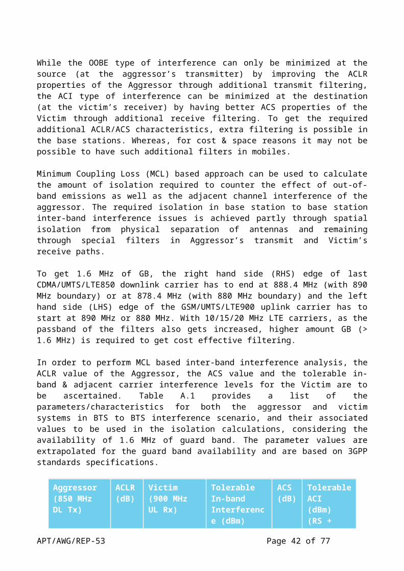
- UMTS850 base station transmit affecting LTE900 base station receive- LTE900 mobile transmit affecting UMTS850 mobile receive
Figure A.11 shown below provides the signal and the interference levels at each point within the entire system considered for the coexistence check interference analysis of UMTS850 Node-B Tx affecting LTE900 eNode-B Rx case, for calculating the OOBE and ACI isolation requirements.
Figure A.11: Signal level diagram for UMTS850 Node-B vs. LTE900 eNode-B case
The max. UMTS850 Node-B Tx OOBE 1.6 MHz away from edge would to be -7 dBm/3.84 MHz (ACLR of 50 dB for 1.6 MHz of GB as per 3GPP TS 25.104). This OOBE would appear as inband interference at the LTE900 eNode-B receive. Tolerable interference level of the LTE900 eNode-B receiver is -107.5 dBm/5 MHz and hence for coexistence of these systems without causing any significant interference issues, the UMTS850 Node-B OOBE has to be suppressed to -107.5 dBm/5 MHz at the LTE900 receiver. With coordinated deployments, assuming a minimum of 60 dB isolation/coupling loss is available from the antenna separation (between UMTS850 and LTE900 base station antennas), still another 40.5 dB of OOBE suppression is required at the UMTS850 transmitter (-7 dBm - 60dB – 40.5dB = -107.5 dBm). In general, Node-B vendors do come up with 10 to 15 dB better ACLR than the specifications. Hence, there is a need for special RF filtering requirement in UMTS850 Node-Bs for additional ACLR of 30 dB.
Typical max. UMTS850 Node-B Tx signal of 43 dBm would be seen as adjacent channel interference (1.6 MHz away from edge) by the LTE900 eNode-B receiver. With antenna isolation of 60 dB between UMTS850 Node-B and LTE900 eNode-B antennas, the estimated UMTS850 Node-B Tx power at LTE900 eNode-B duplexer in is -17 dBm/5 MHz. With additional ACI isolation through RF filtering in LTE900 eNode-B receive filter/duplexer to the tune of 35 dB, the ACI signal of the adjacent band becomes -52 dBm/5 MHz at LTE900 eNode-B receiver. The ACI tolerance level of LTE900 eNode-B receiver is -51.5 dBm (RS+6dB+ACS of 50dB), therefore the ACI check is passed. Hence, the interference problem to LTE900 eNode-B Rx from ACI of the UMTS850 Node-B Tx is manageable with 35 dB of additional filtering at the LTE900 eNode-Bs.
Similar analysis can be performed for the scenario where the LTE900 uplink transmission (UE Transmit) affects the UMTS850 downlink reception (UE receive). Figure A.12 provides signal and
APT/AWG/REP-53 Page 42 of 55
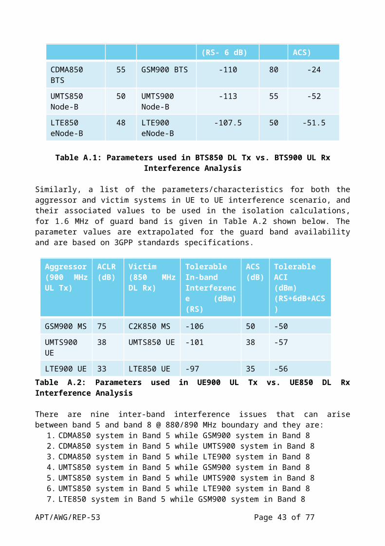
interference levels at each point of the LTE900 UE Tx affecting UMTS850 UE Rx case checking the coexistence interference analysis for calculating the OOBE and ACI isolation requirements.
Figure A.12: Signal levels diagram for LTE900 UE vs. UMTS850 UE case
The max. LTE900 UE Tx OOBE for 1.6 MHz away has to be 33 dB down (as per 3GPP TS 36.101). With typical LTE900 UE max. Tx Power of 20 dBm, the OOBE at the LTE900 UE Tx PA is, 20 -33 = -13 dBm /5 MHz. Considering 5 dB of OOBE isolation is available through LTE900 UE duplexer on Tx path for 1.6 MHz of GB, and also considering a minimum antenna isolation of 40 dB between LTE900 UE and UMTS850 UE with 1m physical separation, the LTE900 UE Tx OOBE at UMTS850 UE duplexer In is -13 -5 -40 = -58 dBm/5 MHz. The tolerable in-band interference at the UMTS850 UE has to be -101 dBm and hence the OOBE interference from LTE900 UE Tx of -58 dBm is much higher than the tolerable level (shortage by 43 dB). It would not be possible to have any special (extra) filtering in mobiles to achieve this 43 dB shortage and therefore OOBE check in UE-to-UE interference case is failed.
Though the max. LTE900 UE Tx signal is 23 dBm, the typical max. would be 20 dBm and that would become an ACI (with 1.6 MHz of GB) to the UMTS850 UE receiver. With antenna isolation of 40 dB between LTE900 UE and UMTS850 UE, estimated LTE900 UE Tx power at UMTS850 UE duplexer in is -20 dBm. Assuming duplexer at UMTS850 UE gives additional 5 dB isolation for ACI signal of LTE900, the LTE900 UE Tx power is down to -25 dBm, before entering the UMTS850 UE receiver. As the ACI tolerance level of UMTS850 UE receiver is - 57 dBm, therefore the ACI check failed (shortage of 32 dB ACS). Hence, ACI interference problem to UMTS850 UE Rx exists from the ACI of the LTE900 UE Tx.
However, the probability of occurrence of LTE900 UE Tx interference to UMTS850 UE Rx is very rare. Hence, the overall chance for such UE to UE interference happening is very remote and therefore, shortage in meeting the OOBE and ACI isolation requirement in UE to UE interference case may be of less concern. Still, there is some probability of meeting all those three conditions in thickly populated areas such as malls, railway stations, airports, convention centers etc., and hence there is a 2 to 5 % chance for the UMTS850 downlink performance degradation.
APT/AWG/REP-53 Page 43 of 55
2.7 Inter-band Interference issues between LTE850 and GSM900 systems
When LTE is being used in band 5 and GSM is being used in band 8 near the 880/890 MHz boundary, there can be two types of potential interference issues and they are:
- LTE850 base station transmit affecting GSM900 base station receive- GSM900 mobile transmit affecting LTE850 mobile receive
Figure A.13 shown below provides the signal and interference levels at each point considered for the coexistence check interference analysis of LTE850 eNode-B transmit affecting GSM900 base station receive case for calculating the OOBE and ACI isolation requirements.
Figure A.13: Signal levels diagram for LTE850 eNode-B vs. GSM900 BTS case
The max. LTE850 eNode-B Tx OOBE at 1.6 MHz (of GB) away would be -7 dBm/5 MHz (as per 3GPP TS 36.104) i.e., -20 dBm/200kHz. Minimum antenna isolation of 60 dB between LTE850 eNode-B and GSM900 BTS antennas can be ensured through coordinated antenna installation. Hence, LTE850 eNode-B Tx OOBE at GSM900 BTS antenna-in is -19 - 60 = -79 dBm/200kHz. As the OOBE interference from LTE850 eNode-B Tx at GSM BTS receiver has to be on par or below the tolerable interference level of -110 dBm (RS - 6 dB), the additional OOBE isolation required through special filters in LTE850 eNode-B Tx path is 31 dB (-79 - (-110)). Hence, the interference problem to GSM900 BTS receiver from the OOBE of the LTE850 eNode-B Tx can be avoided by having 31 dB of additional ACLR in LTE850 eNode-B Tx path.
The max. value of LTE850 eNode-B Tx signal is 43 dBm and this would become an ACI to the GSM900 BTS receiver. Assuming minimum antenna isolation availability of 60 dB between LTE850 eNode-B Tx and GSM900 BTS receiver (through coordinated deployment and certain physical separation distance between the two BTS antennas), the estimated LTE850 eNode-B Tx power at GSM900 BTS receiver-in is 43 -60 -14 (i.e., bandwidth correction factor 10*log 3840/200) = -31 dBm/200kHz. As the ACI tolerance level of GSM900 BTS receiver is -24 dBm (ACS of GSM BTS is 80 dB), therefore the ACI check is passed. Hence, no interference problem to GSM900 BTS Rx from the adjacent channel interference of LTE850 eNode-B Tx.
APT/AWG/REP-53 Page 44 of 55
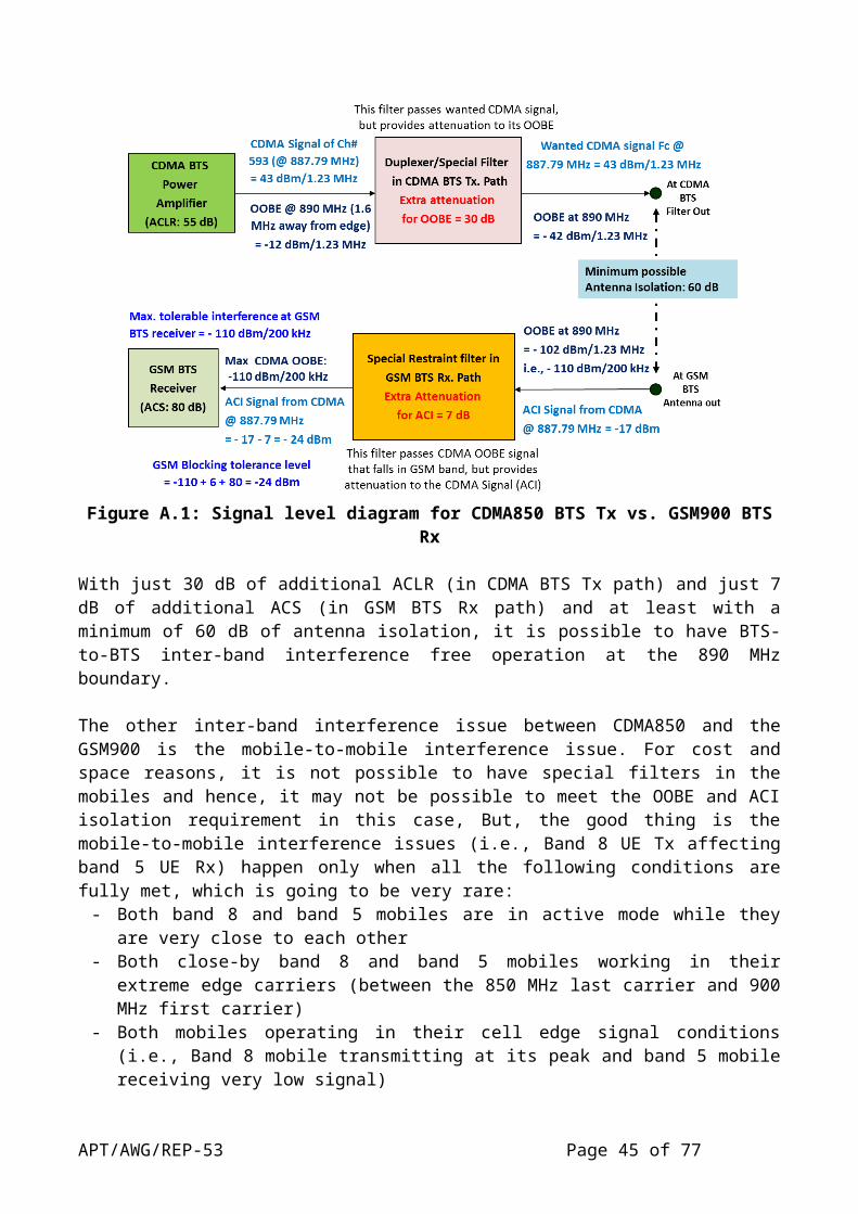
Similar to the above BTS-to-BTS interference analysis, it is also required to perform interference analysis for the GSM900 uplink transmission (MS Transmit) affecting the LTE850 downlink reception (UE receive). Figure A.14 provides signal and interference levels at each point of the GSM900 MS Tx affecting LTE850 UE Rx case checking the coexistence interference analysis to calculate the OOBE and ACI isolation requirements.
Figure A.14: Signal levels diagram for GSM900 MS vs. LTE850 UE case
The max. GSM900 MS Tx OOBE (1.6 MHz away from edge) would be 75 dB down (as per CEPT ECC report 40 & 82). With typical GSM900 MS max. Tx Power = 24 dBm, the OOBE at the GSM900 MS Tx PA output is 24 -75 = -51 dBm /200 kHz. Assuming a minimum antenna isolation of 40 dB available between GSM900 MS and LTE850 UE, GSM900 MS Tx OOBE at UMTS850 UE duplexer-In is -51 -40 = -91 dBm/200 kHz. As the OOBE interference from GSM900 MS Tx is (-91 dBm) is above the RS (-97 dBm) of LTE850 UE receiver, and there is still 6 dB of ACLR shortage to pass the OOBE check.
With typical max. GSM900 MS Tx signal level of 24 dBm/200 kHz and the minimum antenna isolation availability of 40 dB between GSM900 MS and LTE850 UE, the estimated GSM900 MS Tx power at LTE850 UE duplexer in is -16 dBm/200kHz. Assuming the LTE850 UE duplexer also provides additional 5 dB ACI isolation, the GSM900 MS Tx power at LTE850 UE is -21 dBm/5 MHz. As the ACI tolerance level of LTE850 UE receiver is -56 dBm/5 MHz, therefore the ACI check is failed, due to 35 dB (-21 – (-56)) shortage of ACI isolation. The potential impact of this ACI interference can be felt especially in thickly populated areas such as malls, Railway stations, Conference centers etc. The amount of degradation to the LTE downlink capacity can be as high as 5%. However, as highlighted in section 2.1, the probability of occurrence of mobile-to-mobile is very rare.
2.8 Inter-band Interference issues between LTE850 and UMTS900 systems
When LTE technology is being used in one side of 880/890 MHz boundary (i.e., in band 5) and UMTS technology is used the other side (i.e., in band 8), then there can be two types of potential interference issues and they are:
- LTE850 base station transmit affecting UMTS900 base station receive
APT/AWG/REP-53 Page 45 of 55
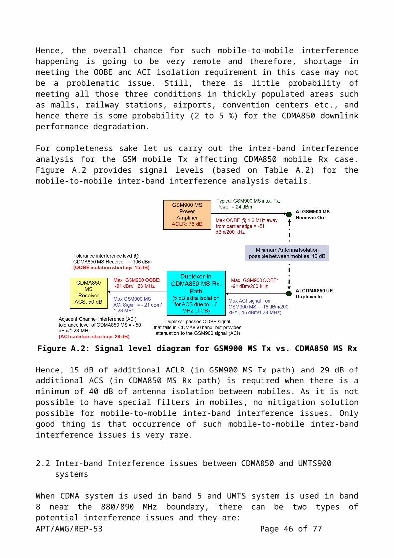
- UMTS900 mobile transmit affecting LTE850 mobile receive
The Figure A.15 shown below provides the signal and interference levels at each point of the entire system considered for coexistence check interference analysis of LTE850 eNode-B Tx affecting UMTS900 Node-B Rx case, for calculating the OOBE and ACI isolation requirements.
Figure A.15: Signal level diagram for LTE850 eNode-B vs. UMTS900 Node-B case
The max. LTE850 eNode-B Tx OOBE 1.6 MHz away from edge would be -5 dBm/5 MHz (ACLR of 48 dB for 1.6 MHz of GB as per 3GPP TS 36.104). This OOBE would appear as inband interference at the UMTS900 Node-B receiver. Tolerable interference level of the UMTS900 Node-B receiver is -113 dBm/3.84 MHz and hence for coexistence of these systems without causing any significant interference issues, the LTE850 eNode-B OOBE has to be suppressed to -113 dBm/3.84 MHz at the UMTS900 receiver. With coordinated deployments, assuming a minimum of 60 dB isolation/coupling loss is available from the antenna separation (between LTE850 and UMTS900 base station antennas), still another 48 dB of OOBE suppression is required at the LTE850 transmitter (-5 dBm - 60dB - 48dB = -113 dBm). In general, eNode-B vendors do come up with 10 to 15 dB better ACLR than the specifications. Hence, there is a need for special RF filtering requirement in LTE850 eNode-Bs for additional ACLR of 35 dB.
Typical max. LTE850 eNode-B Tx signal of 43 dBm would be seen as adjacent channel interference (1.6 MHz away from edge) by the UMTS900 Node-B receiver. With antenna isolation of 60 dB between LTE850 eNode-B Tx and UMTS900 Node-B Rx antennas, the estimated LTE850 eNode-B Tx power at UMTS900 Node-B duplexer-in is -17 dBm. With additional ACI isolation through RF filtering in the UMTS900 Node-B filter/duplexer to the tune of 35 dB the ACI signal of the adjacent band becomes -52 dBm/3.84 MHz at the UMTS900 Node-B receiver, thus meeting the ACI tolerance level of UMTS900 BTS receiver (-52 dBm). The interference problem to UMTS900 BTS Rx from the ACI of the LTE850 eNode-B Tx is manageable with 35 dB of additional filtering at the UMTS900 Node-Bs.
Similar analysis can be performed for the scenario where the UMTS900 uplink transmission (UE Transmit) affects the LTE850 downlink reception (UE receive). Figure A.16 provides signal and
APT/AWG/REP-53 Page 46 of 55
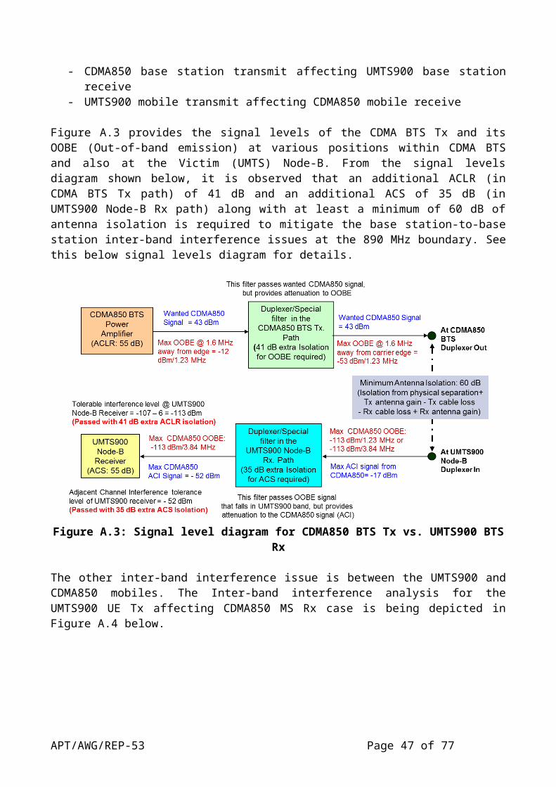
interference levels at each point of the UMTS900 UE Tx affecting LTE850 UE Rx case to check the coexistence interference analysis for calculating the OOBE and ACI isolation requirements.
Figure A.16: Signal levels diagram for UMTS900 UE vs. LTE850 UE case
The max. UMTS900 UE Tx OOBE for 1.6 MHz of GB has to be 38 dB down (as per 3GPP TS 25.101). With typical UMTS900 UE max. Tx Power of 10 dBm, the OOBE at the UMTS900 UE Tx PA is 10 -38 = -28 dBm /3.84MHz. Considering 5 dB of OOBE isolation is available through UMTS900 UE duplexer on Tx path, and also considering a minimum antenna isolation of 40 dB between UMTS900 UE and LTE850 UE with 1m physical separation, the UMTS900 UE Tx OOBE at LTE850 UE duplexer-in is -28 -5 -40 = -73 dBm/3.84MHz. The tolerable in-band interference at the LTE850 UE has to be -97 dBm and hence the OOBE interference from UMTS900 UE Tx of -73 dBm is much higher than the tolerable level (shortage by 24 dB). It would not be possible to have any special (extra) filtering in mobiles to achieve this 24 dB shortage and therefore OOBE check in UE-to-UE interference case has failed.
Though the max. UMTS900 UE Tx signal is 24 dBm, typical max. is at around 10 dBm and that would become an ACI (with 1.6 MHz of GB) to the LTE850 UE receiver. With antenna isolation of 40 dB between UMTS900 UE and LTE850 UE, estimated UMTS900 UE Tx power at LTE850 UE duplexer-in is -30 dBm. Assuming duplexer at LTE850 UE gives additional 5 dB isolation for ACI signal of UMTS900, the UMTS900 UE Tx power is down to -35 dBm, before entering the LTE850 UE receiver. As the ACI tolerance level of LTE850 UE receiver is - 56 dBm, therefore the ACI check failed (shortage of 21 dB ACS). Hence, ACI interference problem to LTE850 UE Rx exists from the ACI of the UMTS900 UE Tx. As the UE to UE interference happening is going to be very remote and therefore, shortage in meeting the OOBE and ACI isolation requirement in this UE-to-UE interference case may not be a problematic issue. In thickly populated areas such as malls, railway stations, airports, convention centers, there is some probability (2 to 5 %) for the LTE850 downlink performance degradation.
2.9 Inter-band Interference Issues between LTE850 and LTE900 Systems
When LTE technology is being used in both sides of 880/890 MHz boundary, then there can be two types of potential interference issues and they are:
- LTE850 base station transmit affecting LTE900 base station receive
APT/AWG/REP-53 Page 47 of 55
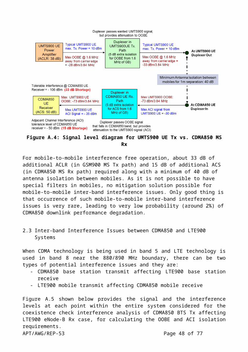
- LTE900 mobile transmit affecting LTE850 mobile receive
Figure A.17 shown below provides the signal and the interference levels at each point within the entire system considered for the coexistence check interference analysis of LTE850 eNode-B Tx affecting LTE900 eNode-B Rx case, for calculating the OOBE and ACI isolation requirements.
Figure A.17: Signal level diagram for LTE850 eNode-B vs. LTE900 eNode-B case
The max. LTE850 eNode-B Tx OOBE 1.6 MHz away from edge would to be -5 dBm/5 MHz (ACLR of 48 dB for 1.6 MHz of GB as per 3GPP TS 36.104). This OOBE would appear as inband interference at the LTE900 eNode-B Rx. Tolerable interference level of the LTE900 eNode-B receiver is -107.5 dBm/5 MHz and hence for coexistence of these systems without causing any significant interference issues, the OOBE of LTE850 eNode-B has to be suppressed to -107.5 dBm/5 MHz (at the LTE900 receiver). With coordinated deployment, a minimum of 60 dB isolation/coupling loss is available between LTE850 and LTE900 base station antennas. For interference free operation, still another 42.5 dB of OOBE suppression is needed at LTE850 eNode-B transmitter (-5 dBm - 60dB – 42.5dB = -107.5 dBm). The eNode-B vendors do come up with 10 to 15 dB better ACLR than the specifications. Hence, there is a need for special RF filtering requirement in LTE850 eNode-Bs for additional ACLR of 30 dB.
Typical max. LTE850 eNode-B Tx signal of 43 dBm would be seen as adjacent channel interference (1.6 MHz away from edge) by the LTE900 eNode-B receiver. With antenna isolation of 60 dB, the estimated LTE850 eNode-B Tx power at LTE900 eNode-B duplexer-in is -17 dBm/5 MHz. With additional ACI isolation through RF filtering in LTE900 eNode-B Rx filter/duplexer to the tune of 35 dB, the ACI signal of the adjacent band becomes -52 dBm/5 MHz at LTE900 eNode-B receiver. The ACI tolerance level of LTE900 eNode-B receiver is -51.5 dBm (RS+6dB+ACS of 50dB), therefore the ACI check is passed. Hence, the interference problem to LTE900 eNode-B Rx from ACI of the LTE850 Node-B Tx is manageable with 35 dB of additional filtering at the LTE900 eNode-Bs.
Similar analysis can be performed for the scenario where the LTE900 uplink transmission (UE Transmit) affects the LTE850 downlink reception (UE receive). Figure A.18 provides signal and
APT/AWG/REP-53 Page 48 of 55
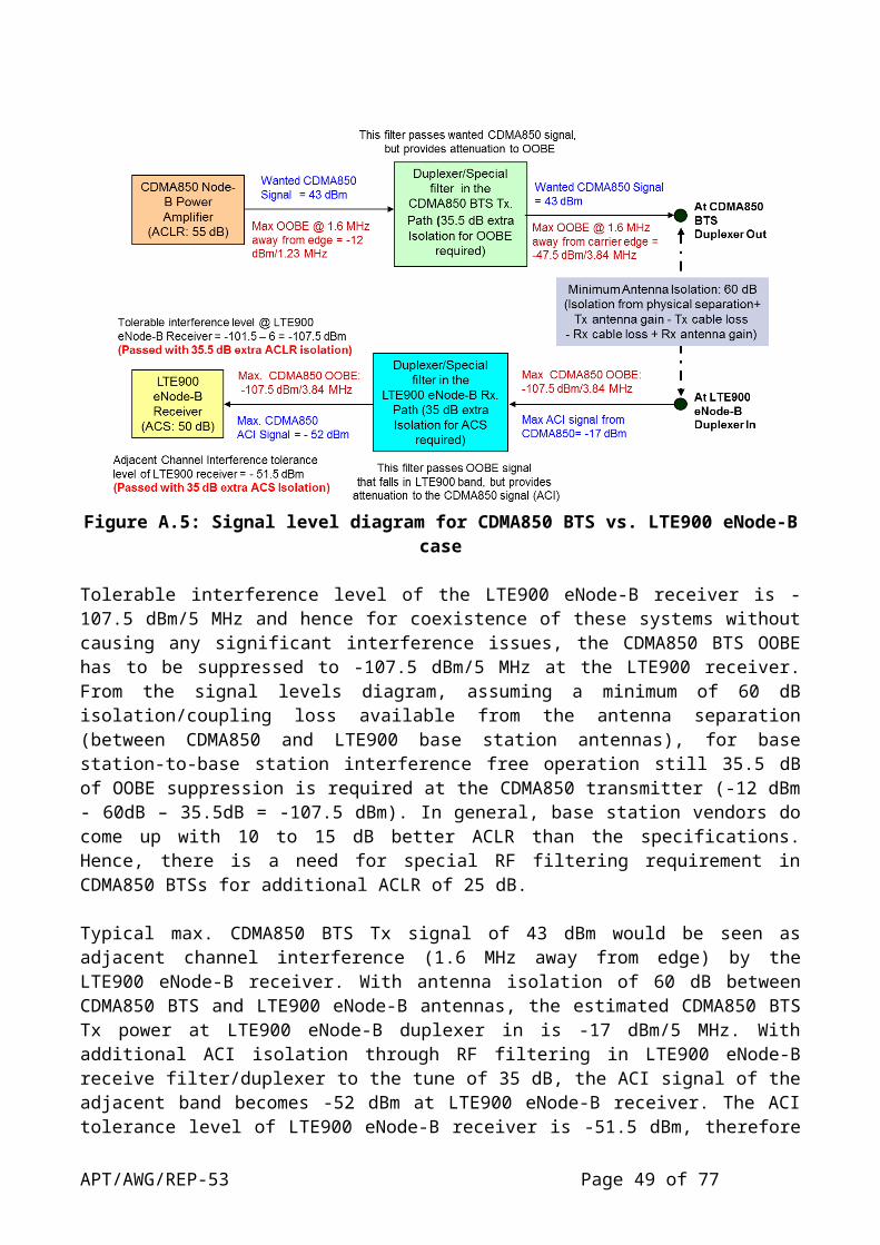
interference levels at each point of the LTE900 UE Tx affecting LTE850 UE Rx case checking the coexistence interference analysis for calculating the OOBE and ACI isolation requirements.
Figure A.18: Signal levels diagram for LTE900 UE vs. LTE850 UE case
The max. LTE900 UE Tx OOBE for 1.6 MHz away has to be 33 dB down (as per 3GPP TS 36.101). With typical LTE900 UE max. Tx Power of 20 dBm, the OOBE at the LTE900 UE Tx PA is, 20 -33 = -13 dBm /5 MHz. Considering 5 dB of OOBE isolation is available through LTE900 UE duplexer on Tx path for 1.6 MHz of GB, and also considering a minimum antenna isolation of 40 dB between LTE900 UE and LTE850 UE with 1m physical separation, the LTE900 UE Tx OOBE at LTE850 UE duplexer In is -13 -5 -40 = -58 dBm/5 MHz. The tolerable in-band interference at the LTE850 UE has to be -97 dBm and hence the OOBE interference from LTE900 UE Tx of -58 dBm is much higher than the tolerable level (shortage by 39 dB). It would not be possible to have any special (extra) filtering in mobiles to achieve this 39 dB shortage and therefore OOBE check in UE-to-UE interference case is failed.
Though the max. LTE900 UE Tx signal is 23 dBm, the typical max. would be 20 dBm and that would become an ACI (with 1.6 MHz of GB) to the LTE850 UE receiver. With antenna isolation of 40 dB between LTE900 UE and LTE850 UE, estimated LTE900 UE Tx power at LTE850 UE duplexer in is -20 dBm. Assuming duplexer at LTE850 UE gives additional 5 dB isolation for ACI signal of LTE900, the LTE900 UE Tx power is down to -25 dBm, before entering the LTE850 UE receiver. As the ACI tolerance level of LTE850 UE receiver is - 56 dBm, therefore the ACI check failed (shortage of 31 dB ACS). Hence, ACI interference problem to LTE850 UE Rx exists from the ACI of the LTE900 UE Tx.
However, the occurrence of LTE900 UE Tx interference on LTE850 UE Rx is very rare. Hence, any shortage in meeting the OOBE and ACI isolation requirement in UE to UE interference case may be of less concern. Still, there is some probability of meeting UE-to-UE interference conditions in thickly populated areas such as malls, railway stations, airports, convention centers etc., and hence there is a 2 to 5 % chance for the LTE850 downlink performance degradation.
2.10 Additional ACLR & ACS requirement Summary with each interference scenario
APT/AWG/REP-53 Page 49 of 55
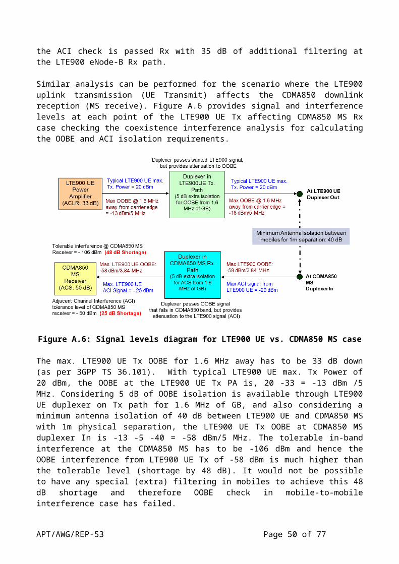
From the inter-band interference analysis performed as part of section 2.1 to section 2.9 of this annexure, it is possible to bring out the amount of additional ACLR and ACS required to mitigate the inter-band base station-to-base station interference issue (i.e., from the base station transmit of CDMA/UMTS/LTE850 (in band 5) on the GSM/UMTS/LTE900 base station receive (in band 8)). Table A.3 shown below provides the needed additional ACLR/ACS to fulfil the interference mitigation requirement through special filters.
Type of Inter-band Interference Issue:
Base Station-to-Base Station scenario with 60 dB of Antenna Isolation guaranty
Extra ACLR needed through special filter in Aggressor BTS Tx path (in dB)
Extra ACS needed through special filter in Victim BTS Rx path (dB)
CDMA850 BTS Tx vs. GSM900 BTS Rx 30 7
CDMA850 BTS Tx vs. UMTS900 Node-B Rx 41 35
CDMA850 BTS Tx vs. LTE900 eNode-B Rx 35.5 35
UMTS850 Node-B Tx vs. GSM900 BTS Rx 30 Nil
UMTS850 Node-B Tx vs. UMTS900 Node-B Rx 46 35
UMTS850 Node-B Tx vs. LTE900 eNode-B Rx 40.5 35
LTE850 eNode-B Tx vs. GSM900 BTS Rx 31 Nil
LTE850 eNode-B Tx vs. UMTS900 Node-B Rx 48 35
LTE850 eNode-B Tx vs. LTE900 eNode-B Rx 42.5 35
Table A.3: Extra ACLR/ACS required in Band 5 BTS Tx affecting Band 8 BTS Rx case
The additional ACLR requirement in CDMA/UMTS/LTE850 base station’s transmit path is varying from 30 to 48 dB and the ACS requirement in the base station’s receive path of CDMA/UMTS/LTE900 is same for all, at 35 dB. Hence, to avoid this inter-band interference issues, it is advisable for the mobile wireless operators to install additional filtering in both CDMA/UMTS/LTE850 and GSM/UMTS/LTE900 base stations at the time of installation itself.
Similar comparison can also be done for the mobile-to-mobile case. As it is not possible to have additional (special) filters in the mobiles, the degradation to band 5 system’s downlink capacity/performance is inevitable. The severity of such interference seems higher with UMTS900 and LTE900 mobiles, as their ACLR properties are inferior compared to the GSM900 mobiles and also they have to deal with higher data rates, thus chances for higher levels of interference to band 5 downlink reception. But, as detailed in sub-section 2.1, the probability of such mobile-to-mobile interference issues happening is very less. Just for completeness sake, let us look at the balance ACLR (in Aggressor mobile Tx path) and ACS (in Victim mobile Rx path) required for interference free operation assess. Table A.4 shown below provides the additional ACLR and ACS requirement, and these values would give us an idea on the severity of mobile-to-mobile interference issues with different technologies usage in band 5 and band 8.
Type of Inter-band Interference Issue: Mobile-to-Mobile scenario with 40 dB of Antenna Isolation guaranty
Balance ACLR still required in Aggressor Mobile Tx path (in dB)
Balance ACS still required in Victim Mobile Rx path (in dB)
GSM900 MS Tx vs. CDMA850 MS Rx 15 29
GSM900 MS Tx vs. UMTS850 UE Rx 33 15
APT/AWG/REP-53 Page 50 of 55
GSM900 MS Tx vs. LTE850 UE Rx 48 25
UMTS900 UE Tx vs. GSM850 MS Rx 10 36
UMTS900 UE Tx vs. UMTS850 UE Rx 28 22
UMTS900 UE Tx vs. LTE850 UE Rx 43 32
LTE900 UE Tx vs. GSM850 MS Rx 6 35
LTE900 UE Tx vs. UMTS850 UE Rx 24 21
LTE900 UE Tx vs. LTE850 UE Rx 39 31
Table A.4: Balance ACLR/ACS required in Band 8 Mobile Tx affecting Band 5 Mobile Rx
3 Intra-band Interference Issues within Band 5/8 Spectrum
With multi-technology deployment in band 5/8 spectrum, there is also a possibility for uplink-uplink or downlink-downlink type of intra-band interference issues due to near-far effect. These downlink-downlink or uplink-uplink type of interference issues get prominent only with non-collocated base stations deployment scenario. This type of interference issues would exist within any band between two adjacent carriers of two different operators when their base stations are not collocated.
If two different technologies are deployed in the adjacent slots of the same band, then the interference issues that we see are from either uplink-uplink or downlink-downlink operation.Such interference issues would be prominent only if those intra-band inter-technology base stations are not collocated, leading to the following four types of interference issues that may degrade the performance of either system.
- System 2 Mobile Tx affecting System 1 Base Station Rx, leading to System 1 uplink performance degradation
- System 1 Base Station Tx affecting System 2 Mobile Rx, leading to System 2 downlink performance degradation
- System 1 Mobile Tx affecting System 2 Base Station Rx, leading to System 2 uplink performance degradation
- System 2 Base Station Tx affecting System 1 Mobile Rx, leading to System 1 downlink performance degradation
In collocated scenario, additional guard band requirement is not necessary between two adjacent & same/different technology carriers because both carriers are emitted from the same location. In such case, condition of minimum wanted signal available in the presence of maximum unwanted signal, doesn’t arise and hence no interference problem. Also, the power control mechanism tries to minimize the level of interference at the victim’s end.
For better understanding of this near-far effect issue in non-collocated base stations scenario, refer to the diagram shown below in Figure A.19.
APT/AWG/REP-53 Page 51 of 55
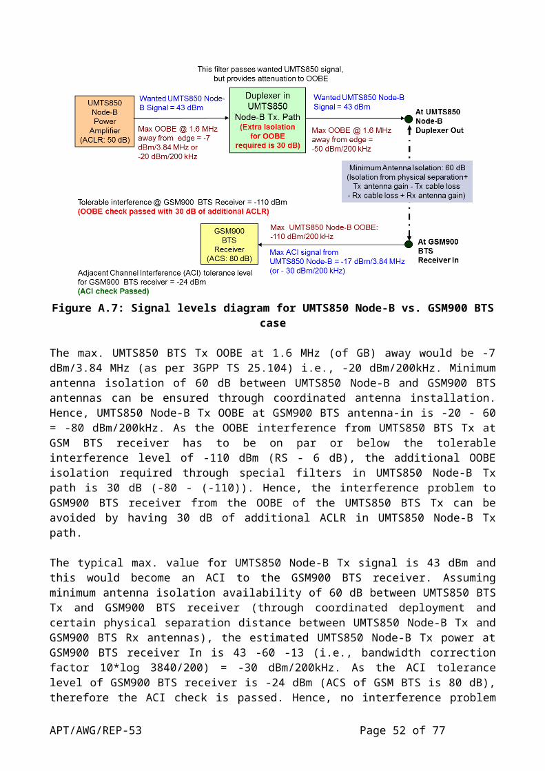
Figure A.19: Intra-band interference issues due to Near-Far effect
Base Station receives minimum possible signal from its own mobiles (to have lesser interference), where as it may see higher levels of adjacent channel interference from other operator’s mobiles working on the adjacent carriers and that leads to degradation in the uplink performance. Similarly, the other base stations can cause downlink performance degradation to the mobiles when the mobiles go closer to other operator base stations. This effect is called near-far problem.
The ACI & OOBE of the adjacent carriers would be the main sources for the near-far problem (uplink-uplink or downlink-downlink interference issues). Two important interference mitigation techniques to avoid such ACI and OOBE effects are:
- Proper antenna location/separation/orientation/down tilts- Proper/improved per-carrier baseband (FIR) filtering in the transmit and receive paths (i.e., to
improve ACLR of Aggressor and ACS of Victim at baseband through additional guard band provision)
This type of ACI & OOBE would be more prominent when the adjacent carrier allocations are with different operators and their base stations are not collocated & there is no sufficient guard band between those inter-operator adjacent carriers to get the required ACLR and ACS values.
Two adjacent LTE and 5 MHz UMTS carriers are designed to work interference free even in non-collocated deployment scenario, because there is sufficient guard band left out within the allocated carrier bandwidth to take care of the near-far problem. If two adjacent UMTS900 carriers or two adjacent LTE900 carriers belonging to two different operators with non-collocated base stations can work interference free with out any extra guard band requirement, then two adjacent LTE900 and UMTS900 carriers can also work interference free as both carriers have additional inherent guard band at the edges. See Figure A.20 for better understanding. The 0.25 MHz of inherent guard band in 5 MHz LTE carrier can not be considered as guard band for near-far problem, because this GB is required for the overall RF filter roll-off. Where as, available 0.4 MHz of inherent guard band at each edge of an UMTS carrier can be considered as guard band to counter the near-far problem, as this GB is beyond the RF filter bandwidth.
APT/AWG/REP-53 Page 52 of 55
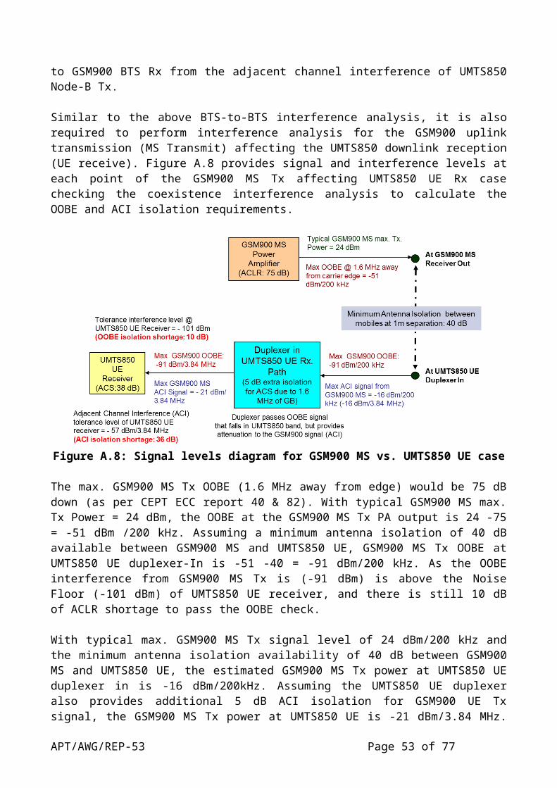
Figure A.20: Inherent guard band provision with UMTS and LTE carriers
The intra-band interference issues would come up when broadband carriers like LTE900 or UMTS900 has to work adjacent to the existing high power narrow band GSM900 carriers. As per CEPT ECC Report 082, uncoordinated (non-collocated) UMTS900 and GSM900 systems can co-exist with a minimum carrier separation of 2.6 MHz between the UMTS900 carrier and the nearest GSM900 carrier. There is no additional guard band requirement to counter the near-far problem, because there is inherent guard band of 0.4 MHz at each edge of the UMTS900 carrier bandwidth. Hence, no additional guard band required from GSM side when two adjacent non-collocated GSM900 and UMTS900 carriers are deployed. Where as, in collocated (coordinated) deployment of UMTS900 and GSM900 carriers (such as UMTS900 overlay on existing GSM900 network), just 2.2 MHz of carrier separation is sufficient.
Additional guard band requirement becomes more essential between two adjacent GSM900 and LTE900 carriers, because GSM carrier is a high power narrow band carrier (all the 43 dBm power is within 200 kHz). As per CEPT ECC Report 40 (dt. 12th Nov 2010), an additional 200 kHz of guard band (carrier separation of 2.8 MHz) between non-collocated LTE and GSM carrier allocations is required to meet the isolation requirement (with improved ACLR & ACS values) to counter the near-far problem. Where as, in collocated (coordinated) deployment, the carrier separation between the two LTE900 and GSM900 carriers (such as LTE overlay on existing GSM900 network), still 2.6 MHz of carrier spacing is required, because a 5 MHz LTE carrier required full 5 MHz for its occupied RF bandwidth. Table A.5 shows the advantage from less GB requirement for the UMTS900 overlay compared to the LTE900 overlay on the existing GSM900 network (i.e., in terms of spectrum saving).
Carrier Separation between UMTS900 & GSM900 carriers
Carrier Separation between a 5 MHz LTE900 carrier & GSM900 carrier
Coordinated Deployment(Same operator)
2.2 MHz 2.6 MHz
Un-coordinated deployment(Different operators)
2.6 MHz 2.8 MHz
Table A.5: Carrier-to-carrier separation requirement in different scenarios
Possible intra-band interference issues between technologies in boths band 5 and band 8, is given below:
- Within Band 8: o Between GSM900 and UMTS900 systemso Between GSM900 and LTE900 systemso Between UMTS900 and LTE900 systems
APT/AWG/REP-53 Page 53 of 55

- Within Band 5:o Between C2K850 and UMTS850 systemso Between C2K850 and LTE850 systems ando Between UMTS850 and LTE850 systems
The only requirement with such near-far effect type on intra-band interference issues is to have some extra guard band between the adjacent slot carriers (i.e., only in case of non-collocated deployment). Table A.6 given below provides the additional guard band requirement for near-far effect issues between two different technology adjacent carriers in a non-collocated deployment scenario.
Case # Adjacent Slot Technologies Additional GB required
1 Between adjacent GSM900 & 5 MHz UMTS900 carriers Nil2 Between adjacent GSM900 & 5 MHz LTE900 carriers 200 kHz3 Between adjacent 5 MHz UMTS900 & LTE900 carriers Nil4 Between adjacent CDMA850 & 5 MHz UMTS850
carriers Nil
5 Between adjacent CDMA850 & 5 MHz LTE850 carriers 350 kHz6 Between adjacent 5 MHz UMTS850 & LTE850 carriers Nil
Table A.6: Additional Guard band requirement for Near-Far effect
In short, a 5 MHz UMTS carrier does have sufficient inherent guard band to take care of the near-far effect related intra-band interference issues with adjacent carriers (either same or different technology carriers). Hence additional GB requirement is nil with cases when one of the adjacent carrier is UMTS. Whereas, with a 5 MHz LTE carrier there is not much inherent GB available and hence additional GB is required when a GSM/C2K carrier is adjacent to a 5 MHz LTE carrier.
4 Conclusions
Both types of interference issues, inter-band as well as intra-band, have to be tackled for the coexistence of different technologies in band 5 and band 8. While the intra-band interference issues exist only in non-collocated/un-coordinated deployments, the inter-band interference issues would exist in both collocated/non-collocated deployment scenarios. The inter-band interference issues between band 5 downlink and band 8 uplink at 880/890 MHz boundary are very severe in nature and needs special attention to solve those interference issues.
In the inter-band interference issues case, there are two different problems, one with band 5 base station transmit signal affecting the performance of band 8 base station receive and the other with band 8 mobile transmit affecting the performance of band 5 mobile receive. In case of less than 90 dB of antenna isolation availability between band 5 base station and band 8 base station antennas, assuming always 10 to 15 dB (more than the standards required value) of additional ACLR and ACS would be available with commerical grade base stations, there is a need for additional ACLR (through OOBE filtering) in the band 5 base station Tx path as well as additional ACS (through ACI filtering) in the band 8 base station Rx path.
In the case of band 8 mobile Tx affecting band 5 mobile Rx, interference free operation is not possible as the additional ACLR/ACS requirement is high and also it is not possible (cost & space point-of-view) to meet this requirement through additional filters in mobiles. However, the probability of mobile to mobile interference happening is very low, because the conditions that two APT/AWG/REP-53 Page 54 of 55
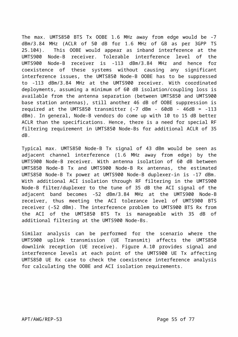
close by band 8 and band 5 mobiles simultaneously in active state and both in weak coverage state is very rare. As there is no additional filtering solution possible in mobiles (no mitigation solution available for the aggressor mobile Tx interference on victim mobile Rx), but because of the probability of such mobile-to-mobile interference happening is going to be less than 2%, the victim downlink degradation possibility would also be very less.
Hence, to avoid inter-band interference issues, it is advisable (to the mobile wireless operators) to procure infrastructure equipment along with such additional filtering in all 2G/3G and 4G base stations at the time of the initial purchase itself. If not done during initial purchase, it is also possible to add these additional filters at a later stage, but at little higher cost and effort.
As the new installations of 3G/4G technologies getting introduced in band 8 spectrum as an overlay (by carving out some spectrum) over the existing GSM technology, special care has to be taken by the operators on two issues. One is choosing the right technology for the overlay and the other is the amount of spectrum to be carved out for the new technology. Also to be kept in mind is the know-how on the possible intra-band & inter-band interference issues and the ways & means to tackle such interference issues.
The intra-band interference issues can occur between two technologies operating in adjacent slots of the spectrum, especially when the base stations of these two technologies are deployed in an uncoordinated fashion. In the overlay with new technology scenario, it is going to be mostly a coordinated deployment and hence no intra-band interference issues may occur. There is a slight advantage for UMTS900 overlay over the LTE900 overlay (in coordinated case), because of the additional guard band availability with a 5 MHz UMTS900 carrier, that allows two extra GSM (TCH) carriers in each side of the UMTS900 carrier (i.e., total of four GSM carriers), compared to no extra GSM carriers possible with a 5 MHz LTE900 carrier. In an un-coordinated (non-collocated) base station deployment (at the edge of operator’s spectrum) case, for minimal intra-band interference; 5 MHz of spectrum is required to be carved out for a UMTS900 carrier and 5.2 MHz of spectrum is required to be carved out for an LTE900 carrier.
To tackle the inter-band interference issues between band 5 and band 8 deployments in the same geopraphical area, it is very essential to install special filters in the band 5 base stations’ Tx path (for improved ACLR) to the tume of 45 dB as well as in the band 8 base stations’ Rx path (for improved ACS) to the tune of 35 dB.
APT/AWG/REP-53 Page 55 of 55