Embed Size (px)
Citation preview

Optical Mounting System for Laboratory Research
Final Design Report
1
Executive Summary
Portland State University is receiving a closed-loop, subsonic wind tunnel to aid in the
research of boundary layer effects, turbulent kinetic energy, and heat transfer effects.
Each of these effects changes the density of the surrounding fluid and may be visually
represented by utilizing Schlieren imaging techniques. Schlieren imaging uses a light
source, convex collimating lenses, concave spherical mirror, and a knife edge to capture
images through a medium. The light travels through the medium, is reflected by a mirror,
travels back through a double convex collimating lens, past the knife edge, and into a
camera. Light refracts differently through various densities of the same fluid. The knife
edge blocks light not refracted through a density gradient, and the camera captures the
density profile as illustrated by captured image. This method provides a very useful
qualitative description of the fluid phenomena occurring through transparent media.
The optical components of this system require precise calibration. To decrease
adjustment time between tests, a frame was needed to hold all of the optical equipment.
With all of the optics mounted to one frame, the entire system may be moved in concert
rather than moving each component individually. This removes the need for adjustment
when moving the system in a single focal plane. Once the focal length is changed, the
system must be recalibrated. Space in the lab is limited, making it difficult for multiple
people to maneuver in the space available. Due to this space restriction, movement and
calibration of the system must be achieved by a single user and be assembled and
disassembled by no more than two people. Only one side of the wind tunnel is easily
accessible, therefore, access to the other side is achieved only by traveling under the test
area. Taking this into account, the optical mounting system was designed such that once
the focal plane is established, calibration and operation may be completed from the user
side of the wind tunnel.
The final design enables the execution of Schlieren imaging by one user and minimizes
adjustments needed by the individual components. Due to the modular properties of the
material used, future integration of additional components and functions will be simple.

Optical Mounting System for Laboratory Research
Final Design Report
2
Table of Contents
Introduction: .................................................................................................................................... 4
Mission Statement: ......................................................................................................................... 5
Summary of Main Design Requirements:........................................................................................ 6
Ease of Use .................................................................................................................................. 6
Optical Component Mounting ..................................................................................................... 6
Mounting Structure and Mobility of Optical Plane ..................................................................... 7
Base Structure ............................................................................................................................. 7
Storage ........................................................................................................................................ 8
Cost .............................................................................................................................................. 8
Top Level Design Alternatives: ........................................................................................................ 8
Final Design Evaluation: ................................................................................................................ 10
Material Selection: ........................................................................................................................ 11
Final Design: .................................................................................................................................. 11
Clamps ....................................................................................................................................... 13
Linear Guide Rails ...................................................................................................................... 15
Optical Mounting Frame ........................................................................................................... 16
Optical Component Mounting ................................................................................................... 17
Cost Analysis .............................................................................................................................. 18
Future Design Considerations: ...................................................................................................... 19
Conclusion: .................................................................................................................................... 20
Appendix A: Components and Equipment for Schlieren Photography ........................................ 21
Appendix B: Initial Design Considerations .................................................................................... 22
Appendix C: Decision Matrices ..................................................................................................... 25
Appendix D: Bill of Materials (BOM) and Quotes ......................................................................... 26
Appendix E: Calculations .............................................................................................................. 29
Appendix E1: Fastener Calculations for Leg Clamps ................................................................. 29
Appendix E2: Deflection Calculation for Linear Guide Rails ..................................................... 32
Appendix E3: Torsional Deflection of Vertical Rise Members .................................................. 35
Appendix E4: Loaded Clamp Deflection Calculation ................................................................ 38
Appendix E5: Calculation for Line-of-sight Deflection .............................................................. 41

Optical Mounting System for Laboratory Research
Final Design Report
3
Appendix F: Additional Technical and Parts Drawings ................................................................. 46
Appendix G: Procedures ............................................................................................................... 56
Appendix G1: Assembly Procedure .......................................................................................... 56
Appendix G2: Operation Manual ............................................................................................. 57
Appendix H: References ............................................................................................................... 60
Optical Mounting System for Laboratory Research
Final Design Report
4
Introduction: Schlieren photography is a method of identifying and imaging many phenomena common
in the fluid sciences. This setup for optics is functional in any of a number of different
configurations. One such configuration is being built and tested for future integration
with the wind tunnel in the Portland State University’s (PSU) Daimler Wind Tunnel
Laboratory. As techniques associated with schlieren photography become increasingly
quantitative, schlieren imaging systems become more advantageous in the laboratory
environment. Figure 1 on the next page shows a schematic of the current optics
arrangement for reference.
Although a relatively simple configuration of optics, schlieren imaging requires a number
of components that need to be carefully aligned in order to function at maximum
potential. In its proposed use with the wind tunnel at PSU, the system will be required to
resolve images in different areas along the entire length of the test area and operate at a
variety of focal depths. In order to collect any meaningful quantitative or qualitative data
from this imaging system, the optics, including a spherical mirror, up to two double-
convex collimating lenses, a camera, and a variety of filters, must be carefully calibrated
and aligned. Appendix A has a complete list of optics currently being used and some
potential components for future experimentation.
In order to mitigate the process of setup and calibration of the optics, Dr. Raul Cal,
Assistant Professor at PSU, has requested that an optics mounting system be designed
and constructed for the laboratory. This mounting system is to add mobility to the optics
without altering the calibration of the optics or changing their relative spacing unless
determined by the user. Additionally, the system should interface with other equipment
intended for lab use and facilitate the future construction of other potential experimental
apparatus where feasible.
Interviews with Dr. Cal have revealed a number of experiments to take place in the wind
tunnel laboratory that will interface or require the use of some of the mounting system

Optical Mounting System for Laboratory Research
Final Design Report
5
designed here. These experiments are discussed more extensively in the Future Design
Considerations section.
Test Area
Spherical M
irro
r Collimating
Lens
Camera
Light
Source
Test Chamber Width 1.2 m
Knife Edge
“Important”
Central 50% of
test area = .6 m
X X
Absolute minimum distance Xis 0.3 m.
Figure 1: Schematic of a schlieren imaging system. Shown is the single-mirror off-axis
configuration selected for use in the PSU wind tunnel.
Mission Statement: This design is to provide a mounting system for all optical components necessary in
schlieren imaging used in the wind tunnel research laboratory at PSU. The mounting
system will be designed to simplify and expedite the setup and calibration of optical
components by allowing such components to move in concert. The mounting system will
minimize the need to recalibrate with any change in focal plane and adhere to all aspects
of the product design specification (PDS). The mounting system is to traverse the length
of the test area on rails that will be used to house additional equipment for other
experiments to be performed in the Daimler Laboratory.

Optical Mounting System for Laboratory Research
Final Design Report
6
Summary of Main Design Requirements: The main customers for this project are Dr. Cal, his research partners, and assistants, who
will be collecting data with this apparatus and training others in future use. Based on
interviews with Dr. Cal throughout the project, the product requirements were divided in
to subsections in order to streamline the design process. Table 1 later in this section
summarizes the PDS targets and the performance generated by the prototype. The
summaries of each subsection of the design requirements are described below in order of
relative importance.
Ease of Use Of the design requirements, the operability of the system is the most important. When
the wind tunnel laboratory is fully operational, there will likely be no more than one or
two researchers present at any given time. Given this constraint, it is important that any
equipment, data acquisition system, or imaging apparatus to be used in the lab be
operable by a single user. The specific requirements for this design were that the system
be calibrated, moved into all functional configurations including the exchange of optical
components, or be moved once disassembled by a single user. The assembly of the
mounting device from its component parts is to be performed by a maximum of two
people in 5 hours or less.
Optical Component Mounting The components used in schlieren photography require careful tuning and calibration.
Optical components may change depending on the nature of the experiment in progress
or the size of the image being resolved. It is required that the individual mounting for
each component be adjustable to accommodate different diameters and focal capabilities
of mirrors, lenses, and cameras. The original requirements listed in the PDS were that
mirrors and lenses of diameters ranging from 7.5 cm to 25.4 cm (3 in. to 10 in.) be
useable with the system. This requirement has been changed by the customer following
successive work with the optics. The range of mirror diameters is now from 15.2 cm to
30.4 cm (6 in. to 12 in.) and the range of lens diameters is now 7.5 cm to 15.2 cm (3 in. to
6 in.). The need for angular mobility (pitch and yaw) adjustable to 10 for the lens

Optical Mounting System for Laboratory Research
Final Design Report
7
remains but has been removed for the mirror as it will remain essentially fixed except for
the ability to translate vertically.
Mounting Structure and Mobility of Optical Plane The original specification for the mounting apparatus stated that the focal plane of any
optics used in experiments need to be mobile about much of the test area. Specifically,
the focal plane of the optics needs to traverse the entire 5-meter length of the test area (x-
direction), the central 50% of the test area (y-direction) and the entire 0.8 m (20 in.)
height of the test area (z-direction). Figure 2 shows the test area with an imposed
coordinate system. The original design requirements stated that the mounting apparatus
was to allow the optical setup to image experiments through the tunnel in a vertical
orientation. This requirement was removed by the customer and allows for a more sleek
design. Regardless of orientation, the assembled mounting structure will span the test
area of the wind tunnel to a maximum of 2 meters.
Figure 2: Schematic of the wind tunnel test area with coordinate system. For the test
area, the doors open to the user side. The inlet is the upper left portion of the test area
and the outlet is the lower right as shown.
Base Structure Initial interviews indicated the base of the mounting device needed to be mobile down the
length of the entire test area. Further, it would need to be sufficiently resilient to support
a wide variety of experimental equipment. If possible, the base is to absorb background
vibration that would otherwise be imparted to the optics from sources such as the fan and
motor of the wind tunnel or from automotive traffic outside the building. At a minimum,
Optical Mounting System for Laboratory Research
Final Design Report
8
the structure would need to support its own weight and up to 20 kg (44 lbs) worth of
optics or equipment. In its fully extended configuration, this could include a moment of
up to 20 N-m (15 ft-lbs). Optics of this nature are sensitive to vibration and change of
alignment. For this reason, the frame should exhibit only minimal deflection under
expect loads.
Storage The Daimler Wind Tunnel Laboratory will be almost entirely occupied by the wind
tunnel itself. This leaves little space in the room for the storage of other equipment.
Thus, the system needs to be removable from the wind tunnel when not in use. All
components of the system must be stored safely and out of the way. If possible the entire
system should fit into a corner of the lab or slide under an elevated section of the wind
tunnel when disassembled.
Cost In all engineering projects, a balance of system performance versus cost needs to be
established. This project was funded by contributions from ASME, Don Mueller
(Director of Student Services and Facilities), and Dr. Cal’s research grant and startup
moneys. Initial estimates on funding indicated resources totaling $1750 for the
completion of the project.
Top Level Design Alternatives:
During the initial round of group design, external searches including a patent search
showed that there were no existing systems that provided a complete solution to the PDS
requirements. Following this search, several rounds of internal searches were undertaken
in order to develop designs capable of satisfying all requirements. This process began
with a series of brainstorming sessions. The major components of the design were
identified as being the base, mounting system, and materials. Two minutes were
dedicated to each of these components in which each team member created a list of
possible solutions. Each idea was evaluated by the team after which a design was

Optical Mounting System for Laboratory Research
Final Design Report
9
generated by each member of the team and submitted to the group for evaluation.
Examples of initial designs can be found in Appendix B.
Prior to performing the final design decision matrix (Appendix C) for overall system
design the combined ideas and concepts were shown to the customer. At this point, the
customer expressed concern regarding several aspects of the proposed designs. Noted in
the Storage subsection, the wind tunnel footprint encompasses most of the usable area in
the laboratory which limits available working space, as illustrated in Figure 3. The
customer concluded the proposed designs were not compatible with the space available.
Figure 3: 3-D rendering of wind tunnel installation in the PSU fluids laboratory. Test
area not shown in the figure. When disassembled, the mounting structure should fit in
back corner (top right of figure) or under part of the tunnel itself.
Dr. Cal decided that simplicity of the optical mounting fixture and conservative use of
space were paramount. A meeting was held Wednesday, 10 March, 2010 to revise the
product design specifications. Upon reviewing the updated design requirements, the
following were eliminated: the ability to resolve images vertically through the test area,
the need for the mounting structure to support itself, and the requirement for individual
optical component motion laterally along the length of the test area. These changes were
finalized with customer approval. A final design was chosen using a weighted scoring
matrix and can be found in Appendix C.
Optical Mounting System for Laboratory Research
Final Design Report
10
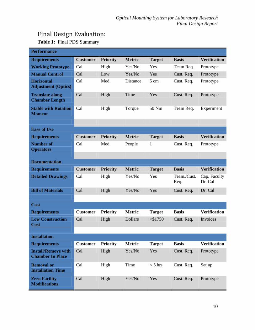
Final Design Evaluation: Table 1: Final PDS Summary
Performance
Requirements Customer Priority Metric Target Basis Verification
Working Prototype Cal High Yes/No Yes Team Req. Prototype
Manual Control Cal Low Yes/No Yes Cust. Req. Prototype
Horizontal
Adjustment (Optics)
Cal Med. Distance 5 cm Cust. Req. Prototype
Translate along
Chamber Length
Cal High Time Yes Cust. Req. Prototype
Stable with Rotation
Moment
Cal High Torque 50 Nm Team Req. Experiment
Ease of Use
Requirements Customer Priority Metric Target Basis Verification
Number of
Operators
Cal Med. People 1 Cust. Req. Prototype
Documentation
Requirements Customer Priority Metric Target Basis Verification
Detailed Drawings Cal High Yes/No Yes Team./Cust.
Req.
Cap. Faculty
Dr. Cal
Bill of Materials Cal High Yes/No Yes Cust. Req. Dr. Cal
Cost
Requirements Customer Priority Metric Target Basis Verification
Low Construction
Cost
Cal High Dollars <$1750 Cust. Req. Invoices
Installation
Requirements Customer Priority Metric Target Basis Verification
Install/Remove with
Chamber In Place
Cal High Yes/No Yes Cust. Req. Prototype
Removal or
Installation Time
Cal High Time < 5 hrs Cust. Req. Set up
Zero Facility
Modifications
Cal High Yes/No Yes Cust. Req. Prototype

Optical Mounting System for Laboratory Research
Final Design Report
11
Material Selection: Once the requirements were finalized, the process of material selection began. From
the initial rounds of design, it was determined that the overall material selection would
dramatically impact the system. Several materials were identified as possible
candidates: (1) square steel tube, (2) UnistrutTM
, and (3) T-SlotTM
(an extruded,
modular aluminum product). An experiment, utilizing strain gauges coupled with
various input loading conditions was devised to compare the materials according to the
following criteria:
Maximum strength per unit mass (corresponds to minimum strain per unit
length)
Greatest self-damping within the material (limits the external damping
necessary for the system as a whole)
Cost, manufacturability, and customer preference were identified as differentiating
criteria. T-SlotTM
was identified as the material of choice through use of a decision
matrix (Appendix C). Although the most expensive solution, T-SlotTM
presented the
greatest versatility in manufacturability with the added advantage of overall maximum
strength per unit mass. Additionally, some portions of the wind tunnel test chamber
already incorporate T-SlotTM
. This presents an opportunity for future compatibility with
other research equipment in the lab.
Final Design: The material selection enabled the final design to progress rapidly. Futura Industries, the
manufacturer of T-SlotTM
, provided an add-in toolbox for SolidWorksTM
which allowed
for virtual design with accurate material dimensions. The add-in also provided guidance
on design limitations of the materials, the ability to address issues concerning
connectivity, a complete bill of materials (BOM), and instructions for fabrication by the
material manufacturer. The complete bill of materials can be found in Appendix D.
Figure 4 depicts a SolidWorksTM
rendering of the final design and its orientation to the
wind tunnel structure utilizing appropriate T-SlotTM
materials and accurate dimensions.

Optical Mounting System for Laboratory Research
Final Design Report
12
Two horizontal guide rails span the length of the wind tunnel test area. These two
members allow the mounting apparatus to travel linearly along the length of the test area
while maintaining a planar relationship with an established line of sight. The support
rails also provide a constant base for location and calibration of the optics.
Figure 4: Rendered final design with relation to wind tunnel test area. For clarity, the
main body of the test area has been hidden; only the support structure to which the
clamps mount is shown.
Figure 5 depicts the final design in greater detail. The upper right corner of the figure
shows the schlieren imaging components attached to an optical mount allowing
adjustment along its length, perpendicular to the test area. In the lower left corner, a
convex spherical mirror is depicted in a 3-point mounting apparatus which can
accommodate mirrors of various sizes.

Optical Mounting System for Laboratory Research
Final Design Report
13
Figure 5: Detailed rendered final design system mounting
Clamps After reviewing the design drawings of the wind tunnel, four 6 in. square tube legs were
identified as support for the test area. To ensure that the wind tunnel is not permanently
modified, compression/friction clamps were designed to attach the horizontal beam
members to the square tube legs. Extreme conditions were considered to determine the
normal force required to sufficiently and safely attach the clamps. The imaging system,
estimated to be 90 kg (200 lbs), was located to one extreme of the test area. Then, an
additional 90 kg (200 lbs) vertical load was added for an additional factor of safety. All
values assumed are worst case estimates of actual loading scenarios. In this situation,
135 kg (300 lbs) of downward force per clamp was estimated. Given the estimated
coefficient of friction for the rubber isolation between the clamps and the legs, 195 kg
(430 lbs) of normal force is required for each clamp [Shigley]. The calculation for
fastener sizing and clamp deflections are shown in Appendix E1.
Initial designs were configured using SolidWorksTM
and Finite Element Analysis (FEA)
was used to determine appropriate material selection. Iterative FEA models determined
1080 steel plate with a minimum 10 gauge thickness was the best choice. This thickness

Optical Mounting System for Laboratory Research
Final Design Report
14
produced material stresses within the elastic range of the steel while remaining easily
positioned by a single operator (Appendix E4).
Fastener sizing was calculated using the desired normal force for the clamps [Shigley].
Various fastener-hole patterns were analyzed resulting in three holes per tab being chosen
to evenly distribute the fastener forces. One quarter inch (1/4”) fasteners were
determined to be sufficient; however, 5/16” were chosen for reliability and to increase the
factor of safety against bolt failure (Appendix E1).
The initial “bucket” design utilized four-fastener holes within the linear rail supports of
the clamps; however, the commercial manufacturing consultant, Ecklund Industries, Inc.,
determined the four-fastener design would need to be fabricated in two pieces to
accommodate the desired hole pattern. The depth of the bucket in the original design was
greater than the width and would require special tooling to manufacture. The proposed
two-piece design would require significant surface preparation prior to welding thus,
dramatically increasing overall production costs. The final design, depicted in Figure 6,
utilizes a simpler to manufacture two-hole bucket, which would be hydraulically press
broken. The figure also includes a photograph of the completed two-piece clamp
assembly. The pocket tab has been welded to the “hat” of the clamp for structural
rigidity. The reverse side of the clamp was designed and fabricated without the front side
mounting bucket. Part drawings are provided in Appendix F.
Figure 6: Detailed rendering of final clamp design and photograph of manufactured
mounting clamps.

Optical Mounting System for Laboratory Research
Final Design Report
15
Linear Guide Rails Two T-Slot
TM ts15-30 beams were chosen to span the distance between clamps. This
material provides compatibility with the imaging structure material, weight savings over
steel and high moment of inertia when orientated correctly. Figure 7 depicts an exploded
view of a wind tunnel test area support leg with support clamps and guide rail.
Figure 7: Detailed rendering of linear guide rail/clamp/test area leg orientation
Vertical deflection was of concern as minimal deviation from an established imaging
plane is desired. The entire imaging system was FEA modeled as a point load (worst
case). Two members spanning 5.25 m (208 in.), the entire length of the test area, support
the optical frame and equipment. One member was modeled as the two beams are
identical and support equal loads. The single member was modeled as a wire frame
beam, simply supported at each end, with two concentrated point loads in the center.
These point loads were separated by 0.46 m (18 in.), the approximate width of the frame.
The frame was conservatively estimated to have a total weight of 45 kg (100 lbs). In the
analysis, each of the two point loads was approximated to be 11.3 kg (25 lbs). The
support beam calculations can be found in Appendix E2.
T-SlotTM
has a complex cross-section; data for the moments of inertial and cross-
sectional areas provided by the manufacturer were used to model the members as a
general profile in AbaqusTM
. Through this method it was determined that the spanning
member will have a maximum deflection of 2 cm (0.78 in.). This deflection was deemed
acceptable as the overall resolution of the system is equal to the radius of the spherical

Optical Mounting System for Laboratory Research
Final Design Report
16
mirror. The radius is greater than the maximum expected deflection, thus affects to the
field of view will not remove the desired focal plane from the calibrated line of sight.
Optical Mounting Frame The optical mounting frame consists of an inner closed loop structure and an outer sleeve
design and is depicted in Figure 8. The loop-sleeve design allows the extreme ends of the
frame to be manually adjusted closer or further away from the wind tunnel test area. This
adjustment is necessary as the internal dimension must vary depending on the focal
length of the mirror used in the schlieren imaging setup. The mirror determines the focal
length of the system and can differ depending on the size of the desired final image.
Figure 8: Detailed rendering of optical frame design.
There are six linear bearings depicted in Figure 8. Four bearings, mounted directly to the
loop-sleeve frame, allowing linear translation along the length of the horizontal beam
member clamped to the square tube legs. Two larger linear bearings are orientated
vertically on the ends of the loop-sleeve design. These bearings facilitate vertical
adjustment of the optical components. Bearings were sized to overcome moments
created by the mass of the optical components affixed to their respective mounting
structures.

Optical Mounting System for Laboratory Research
Final Design Report
17
Optical Component Mounting The mirror optical mount is fabricated from the T-Slot
TM. As shown in Figures 9 and 10,
a vertical member is connected to the optical frame by one of the previously discussed
vertically mounted linear bearings. The vertical member allows travel of approximately
0.8 m (20 in.) for each optical assembly. The linear bearing also acts as a break and
allows for precise line-of-sight adjustment.
Figure 9: Rendered mirror optical mount assembly (left) and rendered camera/light
source optical mount assembly (right).
Figure 10: Detail images of mirror mount showing front (left), back (center), and
exploded view (right) with spherical mirror.
Also depicted in Figure 9, a collimating lens is housed in a double-gimbal structure. This
structure allows for tuning the collimating lens and allows the light returning from the
circular mirror to be focused and conditioned prior to imaging. The assembly was
modeled in SolidWorksTM
to determine viability and compatibility. The two concentric
rings were milled from 1 inch thick 6000 series aluminum using a computer numerical
controlled (CNC) end mill. Once milled, the surface was ground and polished manually.

Optical Mounting System for Laboratory Research
Final Design Report
18
Exact dimensions for all parts of the double-gimbal lens holder may be found in
Appendix F. These dimensions had to be modified from the original SolidWorksTM
design due to the CNC machines inability to machine parts exceeding 26 cm (10.5 in.) in
diameter. Figure 11 features the fabricated final design.
Figure 11: Modeled and fabricated double-gimbal collimating lens assembly.
The fastener holes were located and fabricated using manual measurement and tap and
die tools. The base plate was fabricated from the remnants of the concentric ring
fabrication. The base plate allows for integration with the optical mount assembly
depicted in Figure 9.
Cost Analysis Throughout the project, several iterations of the final design were required to balance the
total cost of the mounting apparatus versus the functionality of the system. The final
design concept approved by Dr. Cal was submitted to Futura Industries. The quote
received was over budget and required modification. An interview with the customer
revealed a preference to compromise the ease of use of the system to accommodate
budget constraints. In order to conform to the cost limit, several linear bearings were
removed or replaced by simple joining plates. While this change means that the system
will require two users to adjust the focal position in some orientations, it does not limit
the degrees of freedom of the system. As the mounting apparatus incurs more use and
Optical Mounting System for Laboratory Research
Final Design Report
19
future funding can be allocated, components will be added back to the system to fully
expand its usability.
Several components and/or the their materials were donated to the project. The
manufacturing and materials for the clamps were donated by Ecklund Industries, Inc.
The aluminum plate from which the double-gimbal lens holder was manufactured was
donated by Colin Kirkendall. With the mentioned donations, the total cost for the project
amounted to $1850, approximately $100 beyond the original estimate for funding. The
budget overrun was approved and covered by Dr. Cal.
Future Design Considerations: The mounting apparatus outlined here was designed to accommodate a variety of optical
components as outlined in the PDS. There are a number of filters that can replace the
knife-edge using the same simple fixture. Cameras may also change; ranging from
digital cameras with telephoto lenses, to Charge Coupled Device (CCD) cameras with
computer interface to high-speed video cameras. All of these have a standard tripod
mount that will work with the current camera mount. The only alteration concern for
cameras is the vertical position for calibration. If adjustments are necessary, a new stand
may need to be manufactured. The PDS outlined that mirror diameters from 15.2 cm to
30.4 cm (6 in. to 12 in.) and lens diameters from 7.5 cm to 15.2 cm (3 in. to 6 in.) be
useable with the mounting device. Any change beyond these diameters could require
additional structural support. To accommodate the addition of a second collimating lens,
another lens holder would need to be purchased or manufactured.
In successive interviews with Dr. Cal, it was proposed that the design be robust enough to
accommodate other research projects or equipment beyond the optics used in schlieren
photography. One such project involves mounting the four cameras necessary for
tomographic particle image velocimetry (tomo-PIV) to the structure. As the mounting
structure already enables changing the position of equipment, adding tomo-PIV would
save time in locating and calibrating equipment. An extension of the proposed PIV work
involves creating a Lagrangian imaging system in which the equipment moves with the
air flows in the tunnel. It may be desirable to automate the system for this research.

Optical Mounting System for Laboratory Research
Final Design Report
20
Automation would involve the addition of an electric motor or drive system to move the
equipment at constant rates and syncing the cameras to the movement with Labview or
another such instrumentation package.
Another proposed set of experiments for the wind tunnel includes modeling off-shore
conditions for wind turbines. To model these conditions, a wave generator and water
tank are being contracted to attach to the floor of the wind tunnel at the exit side. The
support rails have been positioned at the outside of the legs to accommodate this addition.
With the water tank there is a proposed collaborative research project between Dr. Cal
and Dr. Randy Zelick of the PSU Biology department. In this project a support platform
could be constructed to interface with the support rails (and possibly the automation
system mentioned above) to investigate the swimming dynamics and neural response of
fish.
Conclusion: The final design of the optical mounting system met all PDS requirements with the
exceptions of the cost and installation. Future plans for the wind tunnel made a modular
design essential, which required use of the most expensive of potential material selections
for construction.
The final changes to the design were made to limit the overall cost of the system while
maintaining other requirements of the PDS. Additionally, many of the requirements for
verification of the system could not be met. For example, the installation requirement,
“Install/Remove with chamber in place” could not be verified as the wind tunnel delivery
date has been delayed, however, SolidWorks™ models show that the design meets the
requirement. Other verifications delayed include, setup/disassembly time, maximum
system span, and complete mobility of the focal area for schlieren imaging. In the case of
all but the setup/disassembly time, requirements have been verified through design
calculations but still require physical verification upon the completion of the wind tunnel.
Optical Mounting System for Laboratory Research
Final Design Report
21
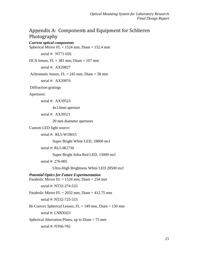
Appendix A: Components and Equipment for Schlieren Photography Current optical components
Spherical Mirror FL = 1524 mm, Diam = 152.4 mm
serial #: NT71-026
DCX lenses, FL = 381 mm, Diam = 107 mm
serial #: AX20827
Achromatic lenses, FL = 245 mm, Diam = 58 mm
serial #: AX20876
Diffraction gratings
Apertures:
serial #: AX39523
4x13mm aperture
serial #: AX39521
20 mm diameter apertures
Custom LED light source:
serial #: RL5-W18015
Super Bright White LED, 18000 mcl
serial #: RL5-IR2730
Super Bright Infra-Red LED, 15000 mcl
serial #: 276-005
Ultra-High Brightness White LED 28500 mcl
Potential Optics for Future Experimentation
Parabolic Mirror FL = 1524 mm, Diam = 254 mm
serial #: NT32-274-533
Parabolic Mirror FL = 2032 mm, Diam = 412.75 mm
serial #: NT32-725-533
Bi-Convex Spherical Lenses, FL = 149 mm, Diam = 150 mm
serial #: LNBX023
Spherical Aberration Plates, up to Diam = 75 mm
serial #: NT66-765
Optical Mounting System for Laboratory Research
Final Design Report
22
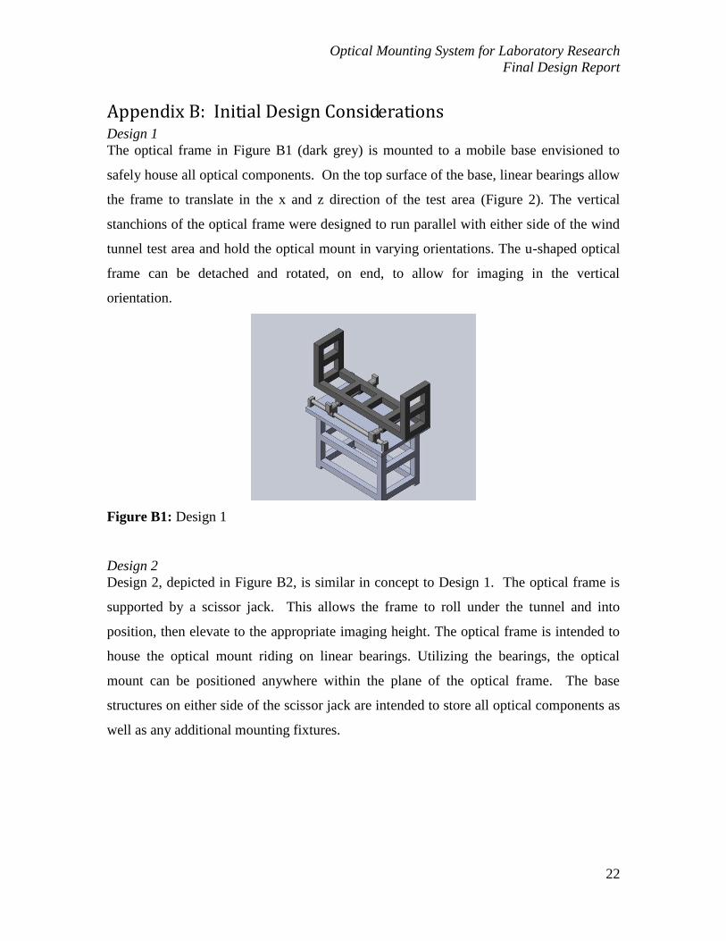
Appendix B: Initial Design Considerations Design 1
The optical frame in Figure B1 (dark grey) is mounted to a mobile base envisioned to
safely house all optical components. On the top surface of the base, linear bearings allow
the frame to translate in the x and z direction of the test area (Figure 2). The vertical
stanchions of the optical frame were designed to run parallel with either side of the wind
tunnel test area and hold the optical mount in varying orientations. The u-shaped optical
frame can be detached and rotated, on end, to allow for imaging in the vertical
orientation.
Figure B1: Design 1
Design 2
Design 2, depicted in Figure B2, is similar in concept to Design 1. The optical frame is
supported by a scissor jack. This allows the frame to roll under the tunnel and into
position, then elevate to the appropriate imaging height. The optical frame is intended to
house the optical mount riding on linear bearings. Utilizing the bearings, the optical
mount can be positioned anywhere within the plane of the optical frame. The base
structures on either side of the scissor jack are intended to store all optical components as
well as any additional mounting fixtures.

Optical Mounting System for Laboratory Research
Final Design Report
23
Figure B2: Design 2
Design 3
Figure B3 shows two optical frames, mounted vertically on two independent base
structures, positioned on either side of the wind tunnel test chamber. Each vertical frame
is slightly larger than one of the four access panels of the wind tunnel (Figure 2).
Telescoping members span the distance between the base structures above and below the
test area. These members may be adjusted to accommodate any width needed between
the optical frames and the test area. The optical components are intended to be attached
to vertical members within the frames. Linear bearings enable positioning of the optics
anywhere within the plane of the frame. This orientation allows for imaging along the
length of the test area. For vertical imaging, the optical mount can be positioned using
the telescoping members running above and below the test area.
Figure B3: Design 3

Optical Mounting System for Laboratory Research
Final Design Report
24
Design 4
The half hoop concept, shown in Figure B4, is intended to allow the optical mounts to
rotate about the tunnel test area. Curved, extruded aluminum I-beam is the major
component of this design and allows rotation through a bearing system designed similarly
to gantry systems currently using I-beams as the load-bearing element. The optical
mounting brackets would be attached to each end. Again, like in previous concepts, the
base structure was conceptualized to hold the varied optical components.
Figure B4: Design 4

Optical Mounting System for Laboratory Research
Final Design Report
25
Appendix C: Decision Matrices Table C1: Decision matrix for design schemes.
Design Weight Cost Ease of
Assembly
Ease of
Adjustment Stability
Range of
Movement
Weighting 0.1 0.3 0.1 0.2 0.15 0.15 Totals
Kukla 4
2
4.5
3
5
3 3.25
Hamilton 3
4
4
3
5
4 3.85
Mastin 3
2
4
3
4
4.5 3.175
Martin 4
2
3.5
3.5
4
4 3.25
Table C2: Decision matrix for construction materials.
Material Cost Manufacturability Modular Strength Weight Aesthetics Compatibility Score
Square tube
steel
10 4 1 7 6 3 2 32
Uni-Strut™ 7 8 10 6 6 4 6 47
T-Slot™ 3 8 10 8 3 10 9 51

Optical Mounting System for Laboratory Research
Final Design Report
26
Appendix D: Bill of Materials (BOM) and Quotes

Optical Mounting System for Laboratory Research
Final Design Report
27

Optical Mounting System for Laboratory Research
Final Design Report
28

Optical Mounting System for Laboratory Research
Final Design Report
29
Appendix E: Calculations
Appendix E1: Fastener Calculations for Leg Clamps Given:
Fasteners for Linear Guide Rail Clamps of the 2010 Optical Mounting Fixture are to be
sized. The two-piece clamp design is used to attach linear guide rails to the legs of the
wind tunnel test area. The clamps are designed to produces a normal force capable of
allowing the frictional forces generated to solely carry the vertically applied loads. The
brackets have been designed using 10 gauge plate steel and a friction/damping
intermediate material (rubber) sandwiched between the bracket and the chamber legs.
Sketch:
See Figure Bracket…..
Data:
Area (A) = 9.894 sq. in.
Area (B) = 28.733 sq. in.
Optical System Weight ~ 200 lb
Load Factor = 3
Find:
Determine the minimal size and grade requirements for the fasteners securing the two
halves of the given clamp design.
Assumptions:
µs(rubber) ~ 0.7

Optical Mounting System for Laboratory Research
Final Design Report
30
Researchers Weight ~ 200 lb
Worst Case: Researcher leans on system while the imaging frame is located to one
extreme of the test area. In this scenario, assume all weight of the imaging system is
carried by two brackets but the entire weight of the researcher is carried by one bracket.
Solution:
In this scenario, each of the two brackets experiences 300 lbs shear (vertical downward).
Find the normal force (N) required to resist this force.
(Eq. TT)
Where
Ff = Force of friction
µs = Coefficient of friction
Solving for N we get:
N = 430 lb
Given the brackets overall size, the design wants to incorporate two or three fasteners per
tab.
The load carried by each fastener:
72 lb (6 fasteners) and 108 lb (4 fasteners)
For nonpermanent (reused fastener) connections the force per faster is calculated by:
(Eq. TY)
(Eq. TU)
Where
Fi = Load Allowed for Reuse of Fastener
Fp = Proof Load
At = Tensile Stress Area
Sp = Proof Strength

Optical Mounting System for Laboratory Research
Final Design Report
31
Fi (4 fasteners) ~ 325 lb
Solving the equation for the proof load
[Fp = (4 bolts) ~ 435 lb]
Fi (6 fasteners) ~ 216 lb
Solving the equation for the proof load
[Fp = (6 bolts) ~ 288 lb]
These values will help size the fasteners
From the Shigley’s [Ref] Table 8-1, 2, 10, the smallest size lowest grade fastener will
support this application. In the end,

Optical Mounting System for Laboratory Research
Final Design Report
32
Appendix E2: Deflection Calculation for Linear Guide Rails Given:
Linear Guide Rails for the 2010 Optical Mounting System are to be tested. The rails are
used to guide the Optical Mount along the length of the wind tunnel test area. The rails
are an extruded aluminum material produced under T-SlotTM
brand name. The vertical
deflection must be quantified to determine limitations of the material and determine
possible design considerations and solutions.
Sketch:
Data:
Length ~ 208 inches
Distributed Load (weight of beam) = 0.2155 lb / in
Optical System Weight ~ 100 lb
Find:
Determine the maximum deflection for the material chosen.
Assumptions:
Worst Case: The imaging frame located in the exact middle of the span. In this scenario,
assume all weight is distributed over two point on each rail 18 inches apart straddling the
exact midpoint of the rails.

Optical Mounting System for Laboratory Research
Final Design Report
33
Solution:
Using the below equations (assuming a point load), manual calculations for the deflection
results by summing the deflections given for each loading condition.
(Eq. TT)
Where
F = Vertical Force
E = Young’s Modulus for Material
I = Area Moment of Inertia
W = Distributed Load
Solving for δ we get:
δ = 0.78 inches
**NOTE: This calculation is to compare with the subsequent FEA model that accurately
distribute the load over two points – it is not the assumed deflection**
AbaqusTM
will be used to determine the deflection given the assumed worst case loading
condition.
Optical Mounting System for Laboratory Research
Final Design Report
34
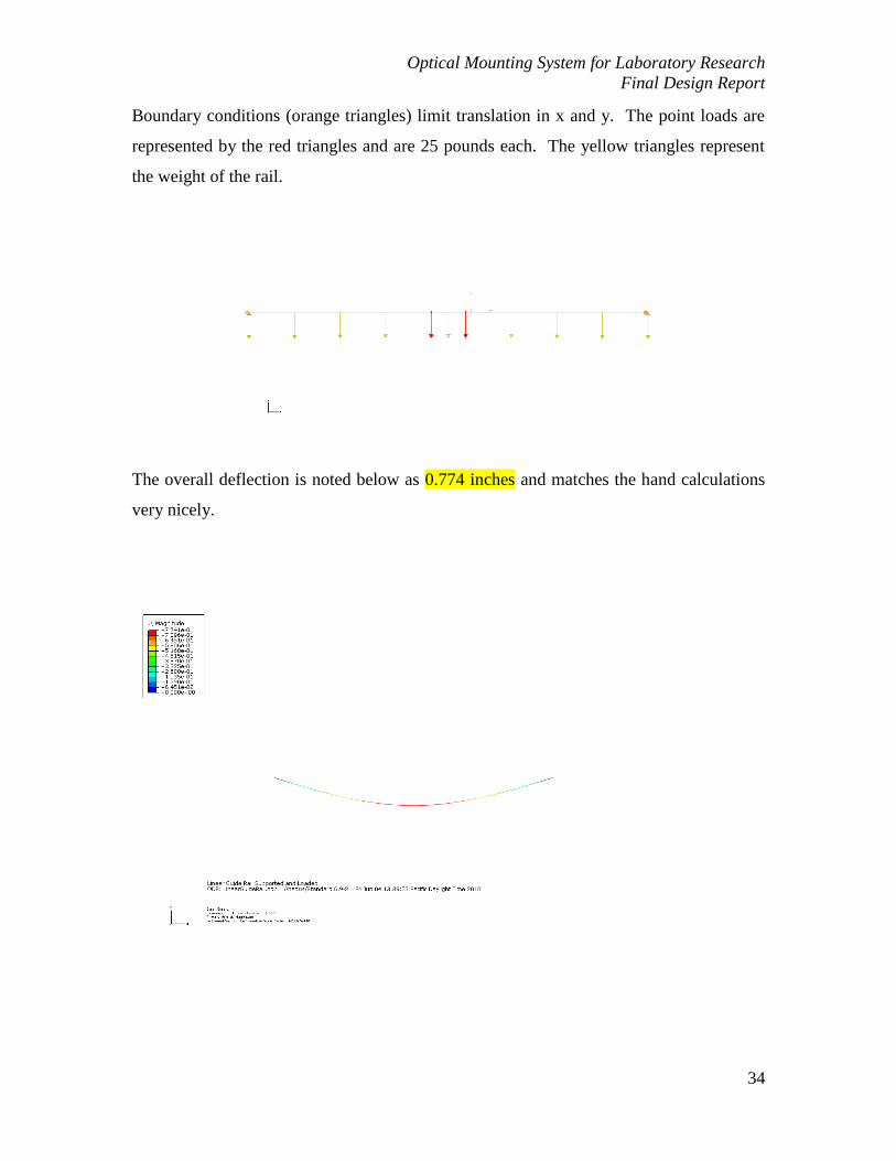
Boundary conditions (orange triangles) limit translation in x and y. The point loads are
represented by the red triangles and are 25 pounds each. The yellow triangles represent
the weight of the rail.
The overall deflection is noted below as 0.774 inches and matches the hand calculations
very nicely.

Optical Mounting System for Laboratory Research
Final Design Report
35
Appendix E3: Torsional Deflection of Vertical Rise Members Given:
Optical frame vertical adjustments for the 2010 Optical Mounting System’s vertical
adjustments are to be tested. The vertical adjustment must be compatible with varied
optical applications; some may require an imbalance of optical components and result in
a moment about the vertical linear bearing. The entire assembly is constructed from an
extruded aluminum material produced under T-SlotTM
brand name.
Sketch:
CCD Camera
Knife Edge
Custom LED Light Source
Lens Mount
Vertical Riser for Optics MountUser Side
Vertical Riser for Optics MountMirror Side
6” Spherical Mirror
120˚ Mirror Supports
Locking Linear Bearing
Diagonal Supports
38” Total Vertical Travel
Data:
For T-SlotTM
P/N 15-30
For T-SlotTM
P/N 15-15
Load to produce 50 N*m (442.5 in*lbs) moment as per PDS
Find:
Determine the maximum deflection.
Assumptions:
Worst Case: The imaging frame is fully extended in the vertical orientation and the
applied load produces a maximum 50 N*m (442.5 in*lbs) moment.

Optical Mounting System for Laboratory Research
Final Design Report
36
Solution:
Inputting the two different geometries for the given material, AbaquaTM
returns a wire
frame model with assumed boundary conditions (zero x-axis translation) and applied load
(22.13 lbs).
To ensure correct material orientation, a rendered wire frame was made.

Optical Mounting System for Laboratory Research
Final Design Report
37
Once all information was verified, AbaqusTM provided the maximum deflection due to
the indicated loading.
Maximum deflection (δ) = 0.0137 inches
This value will be examined and confirmed once the final prototype evaluation takes
place.

Optical Mounting System for Laboratory Research
Final Design Report
38
Appendix E4: Loaded Clamp Deflection Calculation Given:
Minimum Material thickness for the Linear Guide Rail Clamps of the 2010 Optical
Mounting Fixture is to be determined. The two-piece clamp design is used to attach
linear guide rails to the legs of the wind tunnel test area and the baseline material
thickness will be 10 gauge steel plate. The clamps are designed to produces a normal
force capable of allowing the frictional forces generated to solely carry the vertically
applied loads.
Sketch:
Data:
Area (A) = 9.894 sq. in.
Area (B) = 28.733 sq. in.
Optical System Weight ~ 200 lb
Load Factor = 3
Find:
Determine the yield criteria (Von Mises) for the minimum selected material thickness
(10-gauge) sheet steel.
Assumptions:
The three fasteners per side force are assumed to be a point load for the given FEA
model. Additionally, the highest loads will be imposed by the fasteners, not the linear
guide rails. To this end, the cap “pockets” are not modeled.

Optical Mounting System for Laboratory Research
Final Design Report
39
Solution:
After entering the physical parameters into AbaqusTM
as a 2-D wire beam element, the
following boundary conditions and loading were applied. Orange arrows limit translation
and yellow arrows indicate loading conditions. A normal load of 430 lbs was split
between the two clamp tabs.
To ensure the orientation was correct within the program, a rendered view was generated.
After rendering, AbaqusTM
was ran to determine Von Mises stress for the given material
and thickness.

Optical Mounting System for Laboratory Research
Final Design Report
40
According to the model, 10-guage sheet steel experiences 9234 lbs/sq. in. (psi).
Yield strenght for steel is approximately 58000 psi. A bracket of this design with a
miminum

Optical Mounting System for Laboratory Research
Final Design Report
41
Appendix E5: Calculation for Line-of-sight Deflection Given:
Optical frame for the 2010 Optical Mounting System is to be virtually tested to determine
deviation from the optimal line-of-sight. The entire assembly is constructed from an
extruded aluminum material produced under T-SlotTM
brand name.
Sketch:
Vertical Riser for Optics MountMirror Side
Vertical Riser for Optics MountUser Side
Optics Mounting ApparatusSide View
Platform operable at spans from 83.5” to 120”
Vertical Risers operate independently with graduations to provide easy calibration. Risers can be repositioned to vary location of focal plane along the height of the wind tunnel. Platform segments connected with joining plates. Joining plates can be unlocked allowing platform to expand or contract to desired span adjusting depth of focal plane in wind tunnel.
Mounting Platform
Linear bearings allow platform to traverse the length of the wind tunnel on aluminum extrusion rails. Portions of the platform are locked in place by square joining plates that can be released to adjust span of the platform. Vertical rise sections mount directly to mounting platform.
Joining Plates
Linear Bearings
Vertical Rise Mounting(Mirror Side)
Vertical Rise Mounting(User Side)
Linear Bearings
Joining Plates
Data:
For T-SlotTM
P/N 15-30
For T-SlotTM
P/N 15-15

Optical Mounting System for Laboratory Research
Final Design Report
42
Load to produce 20 lbs downward force at the ends (simulating weight of optical mounts)
Find:
Determine the maximum deflection and associated line-of-sight change.
Assumptions:
Worst Case: The imaging frame is in current configuration, using current mirror, and in
an extended configuration, simulating a larger mirror and the required change in focal
length. Weight of optical mounts was calculated using manufacturer information and
rounded up to 20 lbs (almost double actual weight).
Solution:
Inputting the geometries for the given material, AbaquaTM
returned a wire frame model
with assumed boundary conditions (zero x and y-axis translation at the linear bearings)
and applied load (20 lbs).
NOTE: The wire frame only changes slightly for the two configurations, only one is
shown
To ensure correct material orientation, a rendered wire frame was made.

Optical Mounting System for Laboratory Research
Final Design Report
43
The difference in cross-section indicates the sections identified with four cross lengths
and those with two cross lengths (see Sketch above).
Once all information was verified, AbaqusTM
provided the maximum deflection due to
the indicated loading based on the current configuration.
Maximum total deflection (δ) = 0.006183 inches

Optical Mounting System for Laboratory Research
Final Design Report
44
Maximum deflection x-axis (δx) = 0.006068 inches
Using the law of sines, the change from vertical orientation (ϴ) = 0.01738o
Calculating the line of sight change, the change in x-axis dimensions were divided by
vertical height of the optical vertical risers to get a change per inch. This resulted in
0.0003034 inch per inch change. Then, multiplying by the horizontal separation of the
two vertical risers, ~ 85.25 inches, the total line of sight change = 0.026 inch deviation
from nominal line-of-sight.
This process was repeated for an Optical Frame resize of an additional 2 feet. The
boundary conditions remained the same; however, the relationship was verified by a
rendered image.
The analysis produced a maximum deflection in the x-axis of 0.03672 inches.

Optical Mounting System for Laboratory Research
Final Design Report
45
As in the preceding calculations, the line-of-sight change in angle was determined to be
0.1052o. This resulted in 0.03672 inch per inch change. Then, multiplying by the
horizontal separation of the two vertical risers, ~ 109.25 inches, the total line of sight
change = 0.20 inch deviation from nominal line-of-sight.
Result: These dimensions are well within the resolving capability of the mirror and the
optical equipment to be used. An attempt to verify the validity of this model will be
attempted during prototype installation and testing.

Optical Mounting System for Laboratory Research
Final Design Report
46
Appendix F: Additional Technical and Parts Drawings
Vertical Riser for Optics MountMirror Side
Vertical Riser for Optics MountUser Side
Optics Mounting ApparatusSide View
Platform operable at spans from 83.5” to 120”
Vertical Risers operate independently with graduations to provide easy calibration. Risers can be repositioned to vary location of focal plane along the height of the wind tunnel. Platform segments connected with joining plates. Joining plates can be unlocked allowing platform to expand or contract to desired span adjusting depth of focal plane in wind tunnel.
Figure F1: Side view of mounting apparatus with descriptions.
Vertical Riser for Optics MountMirror Side
Vertical Riser for Optics MountUser Side
Optics Mounting ApparatusTop View
Platform operable at spans from 83.5” to 120”
Joining Plates
Linear Bearings Linear Bearings
Figure F2: Top view of mounting apparatus.

Optical Mounting System for Laboratory Research
Final Design Report
47
Mounting Platform
Linear bearings allow platform to traverse the length of the wind tunnel on aluminum extrusion rails. Portions of the platform are locked in place by square joining plates that can be released to adjust span of the platform. Vertical rise sections mount directly to mounting platform.
Joining Plates
Linear Bearings
Vertical Rise Mounting(Mirror Side)
Vertical Rise Mounting(User Side)
Linear Bearings
Joining Plates
Figure F3: Perspective view of mounting platform with description.
Vertical Rise Mounting(Mirror Side)
Vertical Rise Mounting(User Side)
Linear Bearings
Joining Plates
Linear Bearings
Figure F4: Side and top views of support platform. Shown with linear bearings for
longitudinal and vertical translation.
Optical Mounting System for Laboratory Research
Final Design Report
48
CCD Camera
Knife Edge
Custom LED Light Source
Lens Mount
Vertical Riser for Optics MountUser Side Vertical Riser for Optics Mount
User SideFront View
Locking Linear Bearing
Diagonal Supports
20” Vertical Travel
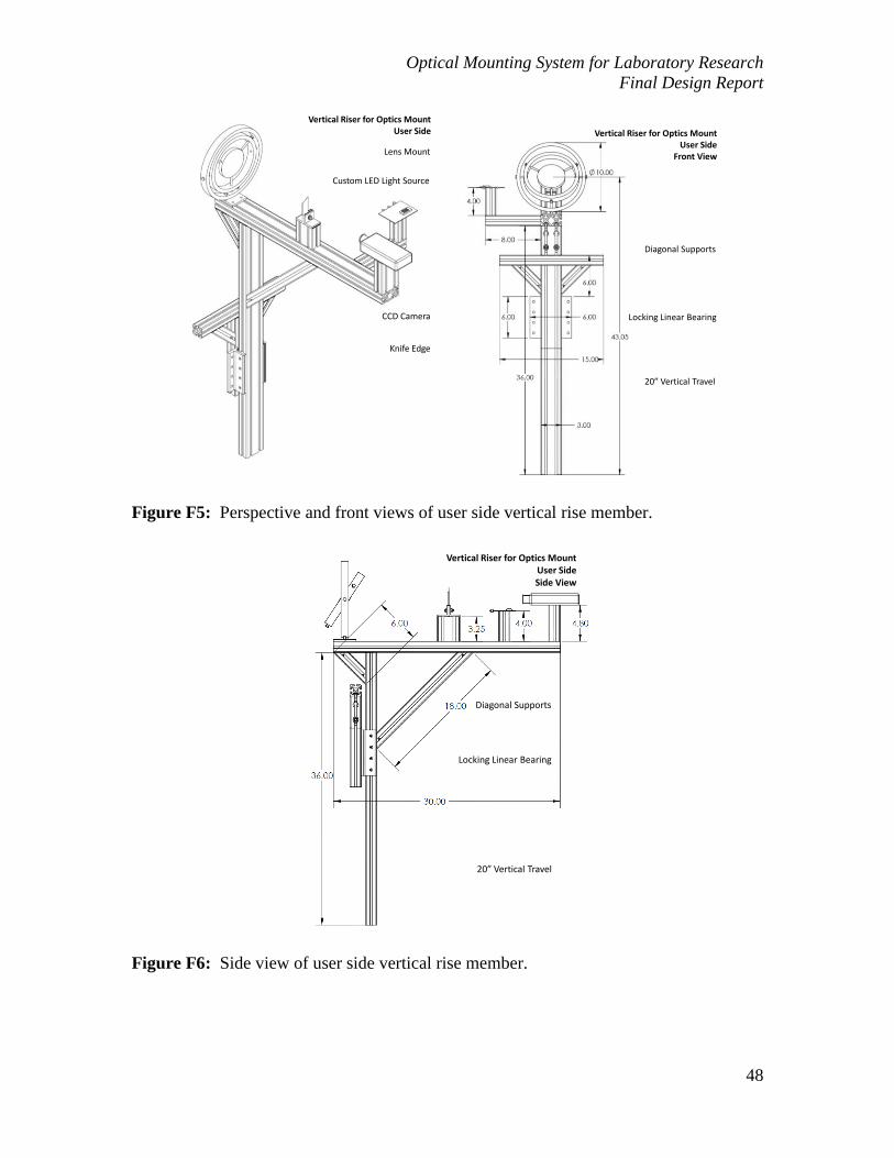
Figure F5: Perspective and front views of user side vertical rise member.
Vertical Riser for Optics MountUser SideSide View
Locking Linear Bearing
Diagonal Supports
20” Vertical Travel
Figure F6: Side view of user side vertical rise member.

Optical Mounting System for Laboratory Research
Final Design Report
49
Vertical Riser for Optics MountMirror Side
6” Spherical Mirror
120˚ Mirror Supports
Locking Linear Bearing
Diagonal Supports
38” Total Vertical Travel
Vertical Riser for Optics MountMirror Side
Front View Side View
Figure F7: Perspective, front, and side views of mirror side vertical rise member.

Optical Mounting System for Laboratory Research
Final Design Report
50
Figure F8: Detailed drawing of the mounting clamp shown configured to hold the
support rail at the left side of the wind tunnel.

Optical Mounting System for Laboratory Research
Final Design Report
51
Figure F9: Detailed drawing of the mounting clamp shown configured to hold the
support rail at the right side of the wind tunnel.

Optical Mounting System for Laboratory Research
Final Design Report
52
Figure F10: Detailed drawing of the mounting clamp shown configured to attach the
backside of both the left- and right-side clamps in Figure GGG8 and Figure GGGp.

Optical Mounting System for Laboratory Research
Final Design Report
53
Double Gimbal Lens Holder
Figure F11: Projected views of the prototype double-gimbal lens holder.
Figure F12: Detailed Drawing of inner ring of the double-gimbal lens holder.

Optical Mounting System for Laboratory Research
Final Design Report
54
Figure F13: Detailed drawings of inner ring of the double-gimbal lens holder.
Figure F14: Detailed drawing of base plate of the double-gimbal lens holder.

Optical Mounting System for Laboratory Research
Final Design Report
55
Custom LED Light Source
Figure F15: Custom LED light source with description
Figure F16: Projected views of the custom LED light source.

Optical Mounting System for Laboratory Research
Final Design Report
56
Appendix G: Procedures
Appendix G1: Assembly Procedure 1. Mount the clamps onto the legs of the wind tunnel test area.
Each leg requires two clamp components: one with a section to hold the
rails (“bucket”) and one without. Choose the clamp components such that
the bucket opens toward the center of the test area (x-direction, refer to
Figure 2).
The top of the clamps should be positioned such that the top edge is
located 6 in. below the bottom of the test area.
Make sure all clamps are level and fasteners are securely applied.
2. Mount the rails to the clamps. Clamps have fastener holes. Specialized hardware
to mount to the aluminum extrusion is available.
3. Assemble and attach the spanning members of the platform to one another as
shown in assembly drawings. Refer to Figures F1 through F4 for orientations of
pieces.
Joining plates should be on the bottom of the connected spanning
members for ease of future adjustment.
The internal crosspiece should be toward the user side of the test area.
Attach vertical members and diagonal supports.
Attach the two 6” linear bearings to the vertical members.
4. Affix the four linear bearings to the rails.
Bearings with locking mechanisms should be on the user side of the wind
tunnel.
Connect the assembled spanning platform to the four linear bearings.
5. Assemble the vertical rise portions.
User Side:
Attach all cross-members and diagonal supports to the vertical
member. With this complete add the risers and arms to position
the camera, knife-edge, and light source. Fix all members in place

Optical Mounting System for Laboratory Research
Final Design Report
57
with provided fasteners. Omit the lens mount and the actual optics
until the mounting apparatus is complete.
Mirror Side:
Attach mirror-mounting pieces to the side of the vertical member
facing the test area. Fix all members in place with provided
fasteners. Omit the spherical or parabolic mirror until the
mounting apparatus is complete.
Attach vertical rise sections to the 6” linear bearings and lock into place.
6. Add optics:
Mirror to be secured by the 120 supports.
Lens to be secured by the mounting screws of the double-gimbal lens
holder.
Camera to be mounted on riser with ¼”-20 thread (standard tripod mount).
Knife-edge (razor blade) clamped between L-brackets.
Light source mounted on support arm with power cord secured to
mounting structure.
Appendix G2: Operation Manual The operation of the mounting device for wind tunnel optics is described in terms of three
subsections: Installing and swapping optical components, calibrating optics and
alignment, and positioning the focal plane in the wind tunnel. Once particular optics
have been selected and calibrated. The system is capable of resolving images in any
position within the same focal plane. While positions at any location down the length of
the wind tunnel and at locations along the vertical height of the test area (x-y plane) do
not require recalibration, changing the depth of focus across the tunnel (z-direction) will
require fine-tuning of the knife edge and camera.
Installing and swapping optical components: It will be the case that the optics
used to collect images in the test area of the wind tunnel will be exchanged
for others during the course of proposed experimentation. Each component

Optical Mounting System for Laboratory Research
Final Design Report
58
will be added or exchanged individually. With all optical components it is
important to keep all surfaces clean. Components should be handled with
appropriate cloths to prevent fingerprints, oils, and dust from being
transferred to optical surfaces.
o The mirror is held by three supports at positions 120 about the
circumference of the mirror. The support at the top of the mirror should
be released first when installing or removing a mirror. This will allow the
two lower supports to hold the mirror while adjustments are made. The
edge of any mirror used should be wrapped in rubber or felt tape to
provide grip and protection to the mirror itself. When the mirror is
removed, or before it is placed, reposition the bottom supports such that
the center of the mirror will be at the marked position on the vertical rise
member. Place the mirror, reposition the top support, and tighten
connective hardware.
o The lens is supported by three set screws in a similar fashion to the mirror.
To install a lens in the holder, position the bottom screws at the desired
radius. Holding the lens in an appropriate cloth, position the lens such that
it is supported on the lower screws. Tighten the top screw until the lens is
secure. Do not over tighten screws. Excessive torque on the screws can
permanently damage lenses. As with the mirror, the edge should be
wrapped in rubber or felt for grip and protection. To remove a lens, hold
the body with an appropriate cloth while the top screw is loosened.
Remove the lens and store in a protected, dust free environment.
o The knife-edge is held vertically between two L-brackets. To change or
reposition the edge, loosen the screw and move the edge into desired
location. Take care, razors are sharp and can cause injury if not treated
appropriately.
o The camera mount is fitted with a standard ¼”-20 thread screw. Any
tripod-ready camera should fit on the mount. Vertical adjustments can be
made by switching vertical riser.

Optical Mounting System for Laboratory Research
Final Design Report
59
Calibrating Optical Components: To make sure all optics are in alignment, place
a laser pointer at the light source or turn on a LED in the light source.
Position the light source such that the center of projection from the light is in
the center of the mirror. Using a hand or a sheet of paper, make sure that the
light reflected from the mirror is centered in the lens. If not, adjust the
alignment of the mirror until this is the case. Using a hand or a sheet of
paper, locate the position of focus of the light coming through the lens. This
is the point where the light is the smallest possible dot. Place the knife edge
at the position of focus, blocking approximately 75% of the light. Place the
camera lens as close to the knife-edge as possible. Check focus to ensure
that light is passing through the lens to the film or CCD.
Positioning the Focal Plane: To change position of the mounting apparatus in-
plane, loosen the locks on the linear bearings attached to the support rails
first. With these unlocked, the entire device should translate easily down the
length of the test area (x-direction). When desired position is reached,
simply relock the bearings. To adjust vertically, each vertical rise member
must be adjusted individually. Adjust the mirror side first. There are
graduations along the vertical members indicating the distance from the
center of focus from the floor of the wind tunnel. Unlock the bearing with
the vertical support firmly held, reposition to desired height (y-direction), and
relock the bearing. Repeat for the user side vertical rise member. Check to
ensure optics are still in focus. If not adjust the user side vertical rise
member. When changing the focal depth of the optics, two users are
required. Loosen the spanning platform from the linear bearings on the user
side. Loosen the fasteners in the joining plates underneath the spanning
platform. Pull the user side vertical member out from or push in toward test
area to desired distance between vertical members. Tighten fasteners in
joining plates. Adjust position of the platform (z-direction) and tighten all
fasteners between linear bearings on the support rails and the spanning
platform. Recalibrate optics as explained above.
Optical Mounting System for Laboratory Research
Final Design Report
60
Appendix H: References
Richard, Budynas and Nesbett, Kieth. Shigley's Mechanical Engineering Design.
McGraw-Hill College, 8th Edition.
"T-Slot". Futura Industries. 2 March 2010 <http://www.tslots.com/>.
Elsinga, G.E., van Oudheusden, B.W., Scarano, F., Watt, D.W. (2004) Assessment and
application of quantitative schlieren methods: Calibrated color schlieren and background
oriented schlieren. Experiments in Fluids. 309-325
Gopal, V., Klosowiak, J. L., Jaeger, R., Selimkhanov, T., and Hartmann, M. J. Z. (2008)
Visualizing the Invisible: the Construction of Three Low-Cost Schlieren Imaging
Systems for the Undergraduate Laboratory. European Journal of Physics. 607- 617
Settles, Gary S. (2001) Schlieren and Shadowgraph Techniques. Springer Berlin Heidelberg,
New York.