Embed Size (px)
Citation preview

EXECUTIVE SUMMARY
This volume presents the technical information in support of the Development Plan Application for theSable Offshore Energy Project. The Project consists of six gas fields that have currently been identified asbeing suitable for initial development: Venture, South Venture,Thebaud, North Triumph, Alma andGlenelg.
The six fields of the Sable Offshore Energy Project were discovered between 1972 and 1986, and are esti-mated to contain approximately 85 billion cubic metres (3 TCF) of recoverable gas. Hydropressured andoverpressured gas accumulations occur in Late Jurassic and Early Cretaceous porous sandstone reservoirs atdepths of 2,800 to 5,000 metres below sea level. Reservoir sandstones are interpreted to be of deltaic andshallow marine origin, associated with a large, ancient delta system which was deposited in the vicinity of thepresent Sable Island area. Repeated delta advance and retreat resulted in a thick, vertically stacked succes-sion of coarsening upward delta progradation cycles. Marine flooding events provided the shale seals toindividual sandstone reservoirs, and gas accumulations are associated with rollover anticlines on the down-thrown side of major down to the basin growth faults. Reservoirs have zonal average porosities of up to 20percent, and permeabilities up to 300 millidarcies. The occurrence of pervasive gain-coating chlorite ischaracteristic of many of the reservoirs, and is believed to have preserved high porosities at great depth byinhibiting the development of quartz cement. Individual sandstone reservoirs in the six project fields aregenerally in the range of 20 to 35 metres in thickness.
The current subsurface database discussed in this volume, consists of well information such as logs, coresand drillstem tests from the existing exploration and delineation wells, as well as 2D, and some 3D seismicdata acquired during the 1980 s. Petrophysical, Geological and Geophysical studies were conducted dur-ing the 1980 s, and early 1990 s. Analyses to date, indicate that modern 3D seismic will significantlyimprove the ability to map reservoir distribution and quality. Plans are in place for the acquisition of 3Dseismic in 1996. Future Geoscience studies will focus on the integration of new 3D seismic data with well-bore data to generate comprehensive geologic and reservoir models for optimized field depletion and reser-voir management.
The reservoir engineering section within this volume describes the data used in the development of reser-voir characterizations for the purpose of individual field and project simulation studies. The individual fieldsimulation studies were conducted to generate depletion plans. The depletion plans included the predict-ed number of required development wells, well offtake rates, well locations, completion details and the over-all field deliverability and recovery efficiency. The integration of the individual field simulation models witha surface network simulator provided the tool necessary for the study of alternative project developmentoptions.
This volume presents the current Project plan that was developed through multiple simulation iterationswith full account for the surface, subsurface and market sales gas rate constraints. The current plan beginsdevelopment with production from Thebaud, Venture and North Triumph and phases in the other fieldsto maintain a production rate of 11.3 E6M3/d for 16 to 17 years. The simulated event sequence indicatesan initial high level of activity for the start of production, with five Venture wells, four Thebaud wells andthree North Triumph wells assumed to be predrilled. In production years five through eight, the remain-ing four Venture wells, two wells in South Venture and five wells each in Alma and Glenelg are added, asrequired, to maintain the desired level of sales gas.
Development Plan Application xvii
Executive Summary

Drilling and Completion planning activities, incorporates the use of two cantilever jack-up drilling rigs capa-ble of working year round in all water depths associated with the Project fields. The pre-drilling of 12 of the28 wells planned for the Project commences using both rigs prior to platform installation. The current planenvisages the use of both water-base and oil-base fluids for different sections of the hole depending on well-bore angle, hole stability and total depth of the well.
The current well completion design uses a step-monobore concept allowing for the flexibility to provide upto 5 inch tubing for deep high-pressure zones and 7 inch tubing for the shallower lower-pressured zones asrequired for deliverability. All wells are planned to contain subsurface safety control valves, polished-borereceptacles and non-damaging packer fluid. The wellhead is planned as a standard configuration with thecapability to sever and seal against wireline or coiled tubing. All completions, testing and major workoversare currently planned to be performed by the jack-up drilling rig(s).
When fully developed, the production facilities for the current development plan will include up to six pro-duction platforms and an accommodation platform. The central facilities at Thebaud will be continuouslymanned, and include wellheads, production and processing equipment and an adjacent accommodationplatform. The remaining fields, Venture, North Triumph, South Venture, Glenelg and Alma will be devel-oped with normally unmanned satellite platforms. These satellites will support wellheads and minimal pro-cessing facilities and be equipped with emergency shelters only. The satellite platforms will be tied-back tothe Thebaud platform via subsea interfield flowlines. A single subsea production gathering pipeline willtransport the gas from Thebaud to an onshore natural gas processing plant, with its related facilities, in theCountry Harbour area. This plant is anticipated to deliver a sales gas volume of 11.3 E6M3/d into theMaritimes and North East Pipeline, supplying markets in Canada and the eastern United States. Naturalgas liquids extracted from the produced gas will be fed by buried pipeline to liquid processing, storage, andshipping facilities in the Point Tupper area.
This volume also describes the facility construction and installation philosophy. The objective is to estab-lish a management structure and Project execution plan that will assure a quality product at low cost with-in an acceptable schedule. The current Project schedule has first gas production by the end of 1999.
The principle associated with the decommissioning and abandonment activities is that such activities will beundertaken in accordance with the regulatory requirements applicable at the time of such activities.Furthermore, abandonment plans will be submitted to the appropriate regulatory authorities for approvalprior to abandonment.
The Environmental, Health and Safety Management (EHSM) system proposed for the Project is describedin the Development Plan, together with the major steps in the system s development. Key components ofthe Environmental, Health and Safety Management system include the Project s Safety Plan, theEnvironmental Protection Plan (EPP) and Contingency Plans. Together these provide the framework formanaging and improving operations, in terms of personnel and public safety and protection of the envi-ronment consistent with the SOEP Project Principles, including:
¥ We will develop this Project with meticulous attention to safety, ensuring that risks to both employees and the public are as low as reasonably possible.
¥ We will meet or exceed Canada s tough standards for environmental protection.¥ We will respect the environmental significance of Sable Island, and the Gully.
xviii Development Plan Application
Executive Summary

The policies, standards and practices of the Project are being developed consistent with a philosophy found-ed on three beliefs:
¥ All environmental, health and safety incidents are preventable.¥ Environmental, health and safety objectives must never be sacrificed for expediency.¥ Environmental, health and safety objectives are an integral part of operations objectives.
The Safety Plan is being developed with a deliberate, systematic and efficient approach, ensuring Projectactivities are planned, organized, executed and maintained in a manner that achieves safety and protectsthe environment. The Environmental Protection Plan will provide detailed guidance for Project personnel,on how to eliminate or minimize any adverse environmental effects from the Project. In addition,Contingency Plans are being developed to ensure the safety of Project personnel and the public, and to pro-tect both the environment and the Proponents investment by establishing procedures for responding toemergency situations. These deal with the response to, and mitigation of, accidental events affecting thesafety of personnel and the public or the integrity if the facilities, and the response to, and mitigation of,accidental release of hazardous substances. An important component of the plans will be coordination withexisting industry and government plans, facilities and equipment.
The subject of Project liability and compensation is also addressed in this volume. Liability may be imposedupon a party responsible for an incident or activity that has impacted the environment while conducting off-shore operations. The Accord legislation as well as fisheries, shipping and other legislation may impose lia-bility for impacts to the environment arising from offshore operations. Voluntary compensation plans andgovernment policy may also establish a basis for liability and compensation. As part of the Project strategyto address compensation, environmental degradation community concerns and financial responsibility mat-ters, a fisheries compensation plan will be filed during activities leading up to construction of facilities forthe Project. Fisheries industry consultation will be ongoing in preparing the plan. Community concernsrelating to the environment have been recorded as part of the pre-filing public consultation program andhave been used as input in certain Project decisions. Evidence of financial responsibility to address pre-scribed liabilities that may be incurred in conducting the Project will be provided prior to the commence-ment of the specific offshore activity in respect of which the applicable financial requirement relates.
The current development strategy is based on present estimates of gas reserves, based primarily on explo-ration seismic data and current projections of future market conditions. As new seismic data, reanalysis ofold data and new engineering studies become available, the development scheme may be altered in signifi-cant ways. For example, the number of wells and/or the sequence of fields may be adjusted during the lifeof the Project or new discoveries may be added. The plan must have sufficient flexibility to also incorporateadvances in technologies and the integration of more accurate real-time information about winds, wavesand currents in the offshore region. Flexibility in responding to these conditions is a key element in theProject development and will be needed in its ongoing regulation.
Development Plan Application xix
Executive Summary

PREFACE
This Development Plan Application (DPA) is Volume 2 of five documents comprising an application forapproval of the Sable Offshore Energy Project. These documents are:
Volume 1 Project OverviewVolume 2 Development Plan ApplicationVolume 3 Environmental Impact StatementVolume 4 Socio-Economic Impact StatementVolume 5 Canada-Nova Scotia Benefits Plan
The purpose of each volume is:
Volume 1 Project Overview:
To summarize the application and to provide a description of the Project in sufficient detail tosatisfy readers interested in a general review.
Volume 2 Development Plan Application:
To describe the gas reservoirs, development strategy, proposed facilities, and Project environ-mental and safety management.
Volume 3 Environmental Impact Statement (EIS):
To describe the physical and biological environment surrounding the Project, assess potentialimpacts and identify ways to minimize them.
Volume 4 Socio-Economic Impact Statement (SEIS):
To describe the socio-economic environment of Nova Scotia, with particular emphasis on theCountry Harbour and Strait of Canso areas; to assess potential socio-economic impacts and dis-cuss ways to minimize them and to maximize potential benefits; to estimate the economicimpacts from the Project.
Volume 5 Canada-Nova Scotia Benefits Plan:
To describe how the Project plans to promote the natural flow of benefits from the Project toNova Scotia and Canada.
The Sable Offshore Energy Project Proponents are: Mobil Oil Canada Properties (Mobil), Lead Operator,Shell Canada Limited (Shell), Joint Operator, Petro-Canada, Imperial Oil Resources Limited (Imperial)and Nova Scotia Resources Limited(NSRL).
The Project is currently planned for development in conjunction with a sales gas pipeline, the Maritimesand Northeast Pipeline Project, to be built from the gas plant at Country Harbour through Nova Scotia, NewBrunswick and the New England states by a consortium of Canadian and American companies. TheProponents are: Westcoast Energy, Inc., Panhandle Eastern Corporation, Mobil Oil Canada Properties and
Development Plan Application i
Preface

TABLE OF CONTENTS
LIST OF FIGURES . . . . . . . . . . . . . . . . . . . . . . . . . . . . . . . . . . .xi
LIST OF TABLES . . . . . . . . . . . . . . . . . . . . . . . . . . . . . . . . . . .xv
EXECUTIVE SUMMARY . . . . . . . . . . . . . . . . . . . . . . . . . . . . .xvii
PART 1
1.0 PROJECT OVERVIEW . . . . . . . . . . . . . . . . . . . . . . . . . . . .1-1
1.1 Introduction . . . . . . . . . . . . . . . . . . . . . . . . . . . . . . . . . . . . . . . . . . . . . . . . .1-1
1.2 Project Scope and Timing . . . . . . . . . . . . . . . . . . . . . . . . . . . . . . . . . . . . . . . . . . . . . . . . .1-2
1.3 Project Development Strategy . . . . . . . . . . . . . . . . . . . . . . . . . . . . . . . . . . . . . . . . . . . . . . . . .1-7
1.4 Project Management . . . . . . . . . . . . . . . . . . . . . . . . . . . . . . . . . . . . . . . . . . . . . . . .1-101.4.1 Project Management Approach . . . . . . . . . . . . . . . . . . . . . . . . . . . . . . . . . . . . . . . . . . .1-101.4.2 Project Principles and Guidelines . . . . . . . . . . . . . . . . . . . . . . . . . . . . . . . . . . . . . . . . .1-101.4.3 Proponent s Experience . . . . . . . . . . . . . . . . . . . . . . . . . . . . . . . . . . . . . . . . . . . . . . . . . . .
1-12
1.5 Regulatory Overview . . . . . . . . . . . . . . . . . . . . . . . . . . . . . . . . . . . . . . . . . . . . . . . .1-12
2.0 GEOLOGY, GEOPHYSICS AND PETROPHYSICS . . . . . . . . .2-1
2.1 Geological Interpretation and Reservoir Description . . . . . . . . . . . . . . . . . . . . . . . . . . . . . . . . .2-12.1.1 Regional Structural Setting . . . . . . . . . . . . . . . . . . . . . . . . . . . . . . . . . . . . . . . . . . . . . . .2-12.1.2 Regional Stratigraphy . . . . . . . . . . . . . . . . . . . . . . . . . . . . . . . . . . . . . . . . . . . . . . . . .2-22.1.3 Source and Trapping of Hydrocarbons . . . . . . . . . . . . . . . . . . . . . . . . . . . . . . . . . . . . .2-52.1.4 Reservoir Stratigraphy . . . . . . . . . . . . . . . . . . . . . . . . . . . . . . . . . . . . . . . . . . . . . . . . .2-72.1.5 Reservoir Sedimentology . . . . . . . . . . . . . . . . . . . . . . . . . . . . . . . . . . . . . . . . . . . . . . . . .2-82.1.6 Reservoir Geophysics . . . . . . . . . . . . . . . . . . . . . . . . . . . . . . . . . . . . . . . . . . . . . . . .2-102.1.7 Reservoir Petrophysics . . . . . . . . . . . . . . . . . . . . . . . . . . . . . . . . . . . . . . . . . . . . . . . .2-122.1.8 Gas In Place . . . . . . . . . . . . . . . . . . . . . . . . . . . . . . . . . . . . . . . . . . . . . . . .2-132.1.9 Future Data Acquisition Strategy . . . . . . . . . . . . . . . . . . . . . . . . . . . . . . . . . . . . . . . . . .2-14
2.2 Field Descriptions . . . . . . . . . . . . . . . . . . . . . . . . . . . . . . . . . . . . . . . . . . . . . . . .2-152.2.1 Thebaud Field . . . . . . . . . . . . . . . . . . . . . . . . . . . . . . . . . . . . . . . . . . . . . . . .2-15
2.2.1.1 Field History . . . . . . . . . . . . . . . . . . . . . . . . . . . . . . . . . . . . . . . . . . . . . . . .2-152.2.1.2 Structural Configuration . . . . . . . . . . . . . . . . . . . . . . . . . . . . . . . . . . . . . . . . .2-162.2.1.3 Geology . . . . . . . . . . . . . . . . . . . . . . . . . . . . . . . . . . . . . . . . . . . . . . . .2-172.2.1.4 Reservoir Zonation . . . . . . . . . . . . . . . . . . . . . . . . . . . . . . . . . . . . . . . . . . . . . .2-18
Development Plan Application iii
Preface

TABLE OF CONTENTS
. . . . . . . . . . . . . . . . . . . . . . . . . . . . . . . . . . . . . . . . . . . . . .Page
2.2.5.5.1 Seismic Database . . . . . . . . . . . . . . . . . . . . . . . . . . . . . . . . . .2-652.2.5.5.2 Time Interpretation . . . . . . . . . . . . . . . . . . . . . . . . . . . . . . . .2-662.2.5.5.3 Depth Conversion . . . . . . . . . . . . . . . . . . . . . . . . . . . . . . . . .2-67
2.2.5.6 Petrophysics . . . . . . . . . . . . . . . . . . . . . . . . . . . . . . . . . . . . . . . . . . . . . . . .2-682.2.5.7 Gas In Place . . . . . . . . . . . . . . . . . . . . . . . . . . . . . . . . . . . . . . . . . . . . . . . .2-69
2.2.6 Alma Field . . . . . . . . . . . . . . . . . . . . . . . . . . . . . . . . . . . . . . . . . . . . . . . .2-712.2.6.1 Field History . . . . . . . . . . . . . . . . . . . . . . . . . . . . . . . . . . . . . . . . . . . . . . . .2-712.2.6.2 Structural Configuration . . . . . . . . . . . . . . . . . . . . . . . . . . . . . . . . . . . . . . . . .2-722.2.6.3 Geology . . . . . . . . . . . . . . . . . . . . . . . . . . . . . . . . . . . . . . . . . . . . . . . .2-732.2.6.4 Reservoir Zonation . . . . . . . . . . . . . . . . . . . . . . . . . . . . . . . . . . . . . . . . . . . . . .2-762.2.6.5 Geophysics . . . . . . . . . . . . . . . . . . . . . . . . . . . . . . . . . . . . . . . . . . . . . . . .2-78
2.2.6.5.1 Seismic Database . . . . . . . . . . . . . . . . . . . . . . . . . . . . . . . . . .2-782.2.6.5.2 Time Interpretation . . . . . . . . . . . . . . . . . . . . . . . . . . . . . . . .2-792.2.6.5.3 Depth Conversion . . . . . . . . . . . . . . . . . . . . . . . . . . . . . . . . .2-80
2.2.6.6 Petrophysics . . . . . . . . . . . . . . . . . . . . . . . . . . . . . . . . . . . . . . . . . . . . . . . .2-802.2.6.7 Gas In Place . . . . . . . . . . . . . . . . . . . . . . . . . . . . . . . . . . . . . . . . . . . . . . . .2-81
3.0 RESERVOIR ENGINEERING . . . . . . . . . . . . . . . . . . . . . . . .3-1
3.1 Reservoir Data . . . . . . . . . . . . . . . . . . . . . . . . . . . . . . . . . . . . . . . . . . . . . . . . .3-13.1.1 Reservoir Mapping . . . . . . . . . . . . . . . . . . . . . . . . . . . . . . . . . . . . . . . . . . . . . . . . .3-13.1.2 Well Test Data . . . . . . . . . . . . . . . . . . . . . . . . . . . . . . . . . . . . . . . . . . . . . . . . .3-33.1.3 Special Core Analysis . . . . . . . . . . . . . . . . . . . . . . . . . . . . . . . . . . . . . . . . . . . . . . . . .3-93.1.4 Reservoir Fluid Properties . . . . . . . . . . . . . . . . . . . . . . . . . . . . . . . . . . . . . . . . . . . . . . .3-11
3.2 Reservoir Simulation . . . . . . . . . . . . . . . . . . . . . . . . . . . . . . . . . . . . . . . . . . . . . . . .3-143.2.1 Individual Field Simulation . . . . . . . . . . . . . . . . . . . . . . . . . . . . . . . . . . . . . . . . . . . . . .3-143.2.2 Integrated Surface-Subsurface Simulation . . . . . . . . . . . . . . . . . . . . . . . . . . . . . . . . . .3-15
3.3 Alternative Depletion Scenarios . . . . . . . . . . . . . . . . . . . . . . . . . . . . . . . . . . . . . . . . . . . . . . . .3-243.4 Reserves . . . . . . . . . . . . . . . . . . . . . . . . . . . . . . . . . . . . . . . . . . . . . . . .3-263.5 Reservoir Management Philosophy . . . . . . . . . . . . . . . . . . . . . . . . . . . . . . . . . . . . . . . . . . . . . .3-27
4.0 DRILLING, COMPLETIONS AND WORKOVERS . . . . . . . . . .4-1
4.1 Strategy . . . . . . . . . . . . . . . . . . . . . . . . . . . . . . . . . . . . . . . . . . . . . . . . .4-14.2 Projected Drilling Schedule . . . . . . . . . . . . . . . . . . . . . . . . . . . . . . . . . . . . . . . . . . . . . . . . .4-34.3 Equipment Selection . . . . . . . . . . . . . . . . . . . . . . . . . . . . . . . . . . . . . . . . . . . . . . . . .4-5
4.3.1 Drillings Rigs and Services . . . . . . . . . . . . . . . . . . . . . . . . . . . . . . . . . . . . . . . . . . . . . . . .4-54.3.2 Mud Handling System . . . . . . . . . . . . . . . . . . . . . . . . . . . . . . . . . . . . . . . . . . . . . . . . .4-54.3.3 Directional Surveying . . . . . . . . . . . . . . . . . . . . . . . . . . . . . . . . . . . . . . . . . . . . . . . . .4-5
4.4 Well Casing and Completion Plans . . . . . . . . . . . . . . . . . . . . . . . . . . . . . . . . . . . . . . . . . . . . . . .4-54.4.1 Casing Design . . . . . . . . . . . . . . . . . . . . . . . . . . . . . . . . . . . . . . . . . . . . . . . . .4-5
Development Plan Application v
Preface
TABLE OF CONTENTS
. . . . . . . . . . . . . . . . . . . . . . . . . . . . . . . . . . . . . . . . . . . . . .Page
5.2.6.2 Subsea Production Gathering Pipeline . . . . . . . . . . . . . . . . . . . . . . . . . . . . . .5-19
5.3 Onshore Facilities . . . . . . . . . . . . . . . . . . . . . . . . . . . . . . . . . . . . . . . . . . . . . . . .5-215.3.1 Scope of Facilities . . . . . . . . . . . . . . . . . . . . . . . . . . . . . . . . . . . . . . . . . . . . . . . .5-215.3.2 Slugcatcher . . . . . . . . . . . . . . . . . . . . . . . . . . . . . . . . . . . . . . . . . . . . . . . .5-215.3.3 Country Harbour Gas Plant . . . . . . . . . . . . . . . . . . . . . . . . . . . . . . . . . . . . . . . . . . . . . .5-235.3.4 Point Tupper Liquid Facilities . . . . . . . . . . . . . . . . . . . . . . . . . . . . . . . . . . . . . . . . . . . .5-245.3.5 Onshore Support Facilities and Services . . . . . . . . . . . . . . . . . . . . . . . . . . . . . . . . . . . .5-25
5.3.5.1 Power . . . . . . . . . . . . . . . . . . . . . . . . . . . . . . . . . . . . . . . . . . . . . . . .5-255.3.5.2 Instrument Air . . . . . . . . . . . . . . . . . . . . . . . . . . . . . . . . . . . . . . . . . . . . . . . .5-255.3.5.3 Fire Protection and Safety Systems . . . . . . . . . . . . . . . . . . . . . . . . . . . . . . . . . .5-255.3.5.4 Relief and Blowdown Systems . . . . . . . . . . . . . . . . . . . . . . . . . . . . . . . . . . . . .5-265.3.5.5 Water Supply . . . . . . . . . . . . . . . . . . . . . . . . . . . . . . . . . . . . . . . . . . . . . . . .5-265.3.5.6 Sewage Disposal . . . . . . . . . . . . . . . . . . . . . . . . . . . . . . . . . . . . . . . . . . . . . . . .5-26
5.3.6 Onshore Natural Gas Liquids Pipeline . . . . . . . . . . . . . . . . . . . . . . . . . . . . . . . . . . . . .5-26
5.4 Production Operations . . . . . . . . . . . . . . . . . . . . . . . . . . . . . . . . . . . . . . . . . . . . . . . .5-285.4.1 Operations Monitoring and Maintenance . . . . . . . . . . . . . . . . . . . . . . . . . . . . . . . . . .5-285.4.2 Inspection Procedures . . . . . . . . . . . . . . . . . . . . . . . . . . . . . . . . . . . . . . . . . . . . . . . .5-285.4.3 Logistics . . . . . . . . . . . . . . . . . . . . . . . . . . . . . . . . . . . . . . . . . . . . . . . .5-285.4.4 Communications . . . . . . . . . . . . . . . . . . . . . . . . . . . . . . . . . . . . . . . . . . . . . . . .5-295.4.5 Control and Monitoring Systems . . . . . . . . . . . . . . . . . . . . . . . . . . . . . . . . . . . . . . . . . .5-295.4.6 Pipeline Control/Leak Detection System . . . . . . . . . . . . . . . . . . . . . . . . . . . . . . . . . . .5-29
5.5 Design Criteria . . . . . . . . . . . . . . . . . . . . . . . . . . . . . . . . . . . . . . . . . . . . . . . .5-295.5.1 Production Facility Preliminary Design Criteria . . . . . . . . . . . . . . . . . . . . . . . . . . . . . .5-295.5.2 Regulation, Codes, Standards and Certification . . . . . . . . . . . . . . . . . . . . . . . . . . . . . .5-30
5.5.2.1 Design Philosophy . . . . . . . . . . . . . . . . . . . . . . . . . . . . . . . . . . . . . . . . . . . . . .5-305.5.2.2 Certifying Authority . . . . . . . . . . . . . . . . . . . . . . . . . . . . . . . . . . . . . . . . . . . . .5-30
5.6 Environmental Criteria . . . . . . . . . . . . . . . . . . . . . . . . . . . . . . . . . . . . . . . . . . . . . . . .5-315.6.1 Preliminary Environmental Criteria . . . . . . . . . . . . . . . . . . . . . . . . . . . . . . . . . . . . . . .5-315.6.2 Environmental Criteria for Engineering Design . . . . . . . . . . . . . . . . . . . . . . . . . . . . . .5-33
5.6.2.1 Meteorological Conditions . . . . . . . . . . . . . . . . . . . . . . . . . . . . . . . . . . . . . . . .5-335.6.2.2 Tides . . . . . . . . . . . . . . . . . . . . . . . . . . . . . . . . . . . . . . . . . . . . . . . .5-335.6.2.3 Extreme Wave Conditions . . . . . . . . . . . . . . . . . . . . . . . . . . . . . . . . . . . . . . . .5-335.6.2.4 Operational Wave Conditions and Normal Wave Conditions . . . . . . . . . . . . .5-345.6.2.5 Wind Speeds . . . . . . . . . . . . . . . . . . . . . . . . . . . . . . . . . . . . . . . . . . . . . . . .5-345.6.2.6 Currents . . . . . . . . . . . . . . . . . . . . . . . . . . . . . . . . . . . . . . . . . . . . . . . .5-345.6.2.7 Ice and Icebergs . . . . . . . . . . . . . . . . . . . . . . . . . . . . . . . . . . . . . . . . . . . . . . . .5-355.6.2.8 Tsunamis . . . . . . . . . . . . . . . . . . . . . . . . . . . . . . . . . . . . . . . . . . . . . . . .5-355.6.2.9 Marine Fouling . . . . . . . . . . . . . . . . . . . . . . . . . . . . . . . . . . . . . . . . . . . . . . . .5-35
5.7 Geotechnical Criteria . . . . . . . . . . . . . . . . . . . . . . . . . . . . . . . . . . . . . . . . . . . . . . . .5-355.7.1 Preliminary Geotechnical Criteria . . . . . . . . . . . . . . . . . . . . . . . . . . . . . . . . . . . . . . . . .5-355.7.2 Geotechnical Conditions and Seismicity . . . . . . . . . . . . . . . . . . . . . . . . . . . . . . . . . . . .5-365.7.3 Bathymetry, Scour and Sediment Transport . . . . . . . . . . . . . . . . . . . . . . . . . . . . . . . . .5-37
5.7.3.1 Baseline Swath Mapping . . . . . . . . . . . . . . . . . . . . . . . . . . . . . . . . . . . . . . . . . .5-395.7.3.2 Other 1995 Swath Survey Objectives . . . . . . . . . . . . . . . . . . . . . . . . . . . . . . . .5-39
Development Plan Application vii
Preface

TABLE OF CONTENTS
. . . . . . . . . . . . . . . . . . . . . . . . . . . . . . . . . . . . . . . . . . . . . .Page
10.0 SAFETY PLAN . . . . . . . . . . . . . . . . . . . . . . . . . . . . . . . 10-1
10.1 Introduction . . . . . . . . . . . . . . . . . . . . . . . . . . . . . . . . . . . . . . . . . . . . . . . .10-110.2 Hazard Management . . . . . . . . . . . . . . . . . . . . . . . . . . . . . . . . . . . . . . . . . . . . . . . .10-310.3 Drilling . . . . . . . . . . . . . . . . . . . . . . . . . . . . . . . . . . . . . . . . . . . . . . . .10-410.4 Construction . . . . . . . . . . . . . . . . . . . . . . . . . . . . . . . . . . . . . . . . . . . . . . . .10-510.5 Operations . . . . . . . . . . . . . . . . . . . . . . . . . . . . . . . . . . . . . . . . . . . . . . . .10-5
10.5.1 Routine Operations . . . . . . . . . . . . . . . . . . . . . . . . . . . . . . . . . . . . . . . . . . . . . . . .10-610.5.2 Management of Change . . . . . . . . . . . . . . . . . . . . . . . . . . . . . . . . . . . . . . . . . . . . . . . .10-710.5.3 Well Servicing Operations . . . . . . . . . . . . . . . . . . . . . . . . . . . . . . . . . . . . . . . . . . . . . . .10-710.5.4 Emergency Preparedness . . . . . . . . . . . . . . . . . . . . . . . . . . . . . . . . . . . . . . . . . . . . . . . .10-8
11.0 ENVIRONMENTAL PROTECTION PLAN . . . . . . . . . . . . . 11-1
11.1 Introduction . . . . . . . . . . . . . . . . . . . . . . . . . . . . . . . . . . . . . . . . . . . . . . . .11-111.2 Construction . . . . . . . . . . . . . . . . . . . . . . . . . . . . . . . . . . . . . . . . . . . . . . . .11-211.3 Drilling, Completions and Workovers . . . . . . . . . . . . . . . . . . . . . . . . . . . . . . . . . . . . . . . . . . . .11-311.4 Operations . . . . . . . . . . . . . . . . . . . . . . . . . . . . . . . . . . . . . . . . . . . . . . . .11-311.5 Decommissioning and Abandonment . . . . . . . . . . . . . . . . . . . . . . . . . . . . . . . . . . . . . . . . . . . .11-4
12.0 CONTINGENCY PLANS . . . . . . . . . . . . . . . . . . . . . . . . .12-1
12.1 Introduction . . . . . . . . . . . . . . . . . . . . . . . . . . . . . . . . . . . . . . . . . . . . . . . .12-112.2 Offshore ERP . . . . . . . . . . . . . . . . . . . . . . . . . . . . . . . . . . . . . . . . . . . . . . . .12-212.3 Loss of Well Control (Drilling & Well Servicing) . . . . . . . . . . . . . . . . . . . . . . . . . . . . . . . . . . . .12-312.4 Gathering Line Breaks . . . . . . . . . . . . . . . . . . . . . . . . . . . . . . . . . . . . . . . . . . . . . . . .12-412.5 Platform Incidents . . . . . . . . . . . . . . . . . . . . . . . . . . . . . . . . . . . . . . . . . . . . . . . .12-412.6 Collision . . . . . . . . . . . . . . . . . . . . . . . . . . . . . . . . . . . . . . . . . . . . . . . .12-412.7 Marine Incidents . . . . . . . . . . . . . . . . . . . . . . . . . . . . . . . . . . . . . . . . . . . . . . . .12-512.8 Aviation Incidents . . . . . . . . . . . . . . . . . . . . . . . . . . . . . . . . . . . . . . . . . . . . . . . .12-512.9 Force Majeure . . . . . . . . . . . . . . . . . . . . . . . . . . . . . . . . . . . . . . . . . . . . . . . .12-612.10 Onshore ERP . . . . . . . . . . . . . . . . . . . . . . . . . . . . . . . . . . . . . . . . . . . . . . . .12-612.11 Fire/Explosion . . . . . . . . . . . . . . . . . . . . . . . . . . . . . . . . . . . . . . . . . . . . . . . .12-712.12 Serious Injury/Fatality . . . . . . . . . . . . . . . . . . . . . . . . . . . . . . . . . . . . . . . . . . . . . . . .12-812.13 Spills . . . . . . . . . . . . . . . . . . . . . . . . . . . . . . . . . . . . . . . . . . . . . . . .12-8
PART 2:
BIBLIOGRAPHY
Development Plan Application ix
Preface

FiguresRef. # Title . . . . . . . . . . . . . . . . . . . . . . . . . . . . . . . . . . . . . . . . . . . . . .Page
1.0 Project Overview
1.1 Current Development Plan Summary . . . . . . . . . . . . . . . . . . . . . . . . . . . . . . . .1-21.2 Project Facilities . . . . . . . . . . . . . . . . . . . . . . . . . . . . . . . . . . . . . . . . . . . . . . . . .1-41.3 Proposed Project Schedule . . . . . . . . . . . . . . . . . . . . . . . . . . . . . . . . . . . . . . . .1-61.4 Project Development Process . . . . . . . . . . . . . . . . . . . . . . . . . . . . . . . . . . . . . . .1-81.5 Schedule of Project Activities . . . . . . . . . . . . . . . . . . . . . . . . . . . . . . . . . . . . . . .1-91.6 Project Principles and Guidelines . . . . . . . . . . . . . . . . . . . . . . . . . . . . . . . . . .1-11
2.0 Geology, Geophysics and Petrophysics
2.1.1.1 Location of Scotian Shelf . . . . . . . . . . . . . . . . . . . . . . . . . . . . . . . . . . . . . . . . . .2-12.1.1.2 Tectonic Elements of the Scotian Basin . . . . . . . . . . . . . . . . . . . . . . . . . . . . . . .2-22.1.2.1 Generalized Stratigraphy of the Scotian Shelf . . . . . . . . . . . . . . . . . . . . . . . . . .2-32.1.2.2 Depositional Components of a Delta System . . . . . . . . . . . . . . . . . . . . . . . . . . .2-42.1.2.3 Paleogeographic Map of Sable Island Delta Complex . . . . . . . . . . . . . . . . . . . .2-52.1.3.1(a) Sequential Development of Growth Faults . . . . . . . . . . . . . . . . . . . . . . . . . . . .2-62.1.3.1(b) North-South Seismic Line Showing Growth Faults . . . . . . . . . . . . . . . . . . . . . .2-72.1.4.1 Diagrammatic North-South Cross-section of Missasauga Formation . . . . . . . . .2-82.1.5.1 Stratigraphic Log . . . . . . . . . . . . . . . . . . . . . . . . . . . . . . . . . . . . . . . . . . . . . . . .2-92.1.5.2 Facies Model, Sable Delta . . . . . . . . . . . . . . . . . . . . . . . . . . . . . . . . . . . . . . . . .2-102.1.6.1 Primary Regional Seismic Reflectors Scotian Basin . . . . . . . . . . . . . . . . . . . . .2-11
2.2.1.1.1 Thebaud Top Sand A Depth Structure Map . . . . . . . . . . . . . . . . . . . . . . . . . .2-162.2.1.3.1 Thebaud Sand A Net Pay Thickness Map . . . . . . . . . . . . . . . . . . . . . . . . . . . .2-182.2.1.4.1 Thebaud Schematic Structural Cross-section . . . . . . . . . . . . . . . . . . . . . . . . . .2-192.2.1.5.1.1 Thebaud Seismic Database Map . . . . . . . . . . . . . . . . . . . . . . . . . . . . . . . . . . . .2-212.2.1.5.2.1 Thebaud Seismic Line . . . . . . . . . . . . . . . . . . . . . . . . . . . . . . . . . . . . . . . . . . .2-22
2.2.2.1.1 Venture Top Sand 6 Upper Depth Structure Map . . . . . . . . . . . . . . . . . . . . .2-272.2.2.3.1 Venture Sand 6 Upper Net Pay Thickness Map . . . . . . . . . . . . . . . . . . . . . . . .2-292.2.2.4.1 Venture Schematic Structural Cross-section . . . . . . . . . . . . . . . . . . . . . . . . . .2-302.2.2.5.1.1 Venture Seismic Database Map . . . . . . . . . . . . . . . . . . . . . . . . . . . . . . . . . . . .2-322.2.2.5.2.1 Venture Seismic Line . . . . . . . . . . . . . . . . . . . . . . . . . . . . . . . . . . . . . . . . . . . .2-33
2.2.3.1.1 North Triumph Top Missisauga, Depth Structure Map . . . . . . . . . . . . . . . . . 2-402.2.3.3.1 North Triumph Net Pay Map . . . . . . . . . . . . . . . . . . . . . . . . . . . . . . . . . . . . . .2-422.2.3.4.1 North Triumph Schematic Structural Cross-section . . . . . . . . . . . . . . . . . . . .2-432.2.3.5.1.1 North Triumph Seismic Database Map . . . . . . . . . . . . . . . . . . . . . . . . . . . . . .2-442.2.3.5.2.1 North Triumph Seismic Section . . . . . . . . . . . . . . . . . . . . . . . . . . . . . . . . . . . .2-46
2.2.4.1.1 South Venture Top Sand 2 Structure Map . . . . . . . . . . . . . . . . . . . . . . . . . . .2-492.2.4.3.1 South Venture Sand 2 Net Pay Thickness Map . . . . . . . . . . . . . . . . . . . . . . . .2-502.2.4.4.1 South Venture Schematic Structural Cross-section . . . . . . . . . . . . . . . . . . . . .2-512.2.4.5.1.1 South Venture Seismic Database Map . . . . . . . . . . . . . . . . . . . . . . . . . . . . . . .2-532.2.4.5.2.1 South Venture Seismic Line . . . . . . . . . . . . . . . . . . . . . . . . . . . . . . . . . . . . . . .2-54
Development Plan Application xi
Preface
FIGURES cont d.
Ref. # Title . . . . . . . . . . . . . . . . . . . . . . . . . . . . . . . . . . . . . . . . . . . . . .Page
5.2.6.1.1 Pipeline Corridors . . . . . . . . . . . . . . . . . . . . . . . . . . . . . . . . . . . . . . . . . . . . . .5-185.3.1.1 Process Block Flow Diagram . . . . . . . . . . . . . . . . . . . . . . . . . . . . . . . . . . . . . . .5-215.3.2.1 Typical Slugcatcher . . . . . . . . . . . . . . . . . . . . . . . . . . . . . . . . . . . . . . . . . . . . .5-225.3.3.1 Typical Gas Plant . . . . . . . . . . . . . . . . . . . . . . . . . . . . . . . . . . . . . . . . . . . . . . .5-235.3.6.1 Preliminary Liquids Pipeline Corridor . . . . . . . . . . . . . . . . . . . . . . . . . . . . . . .5-275.7.3.1 Sable Bathymetry Map . . . . . . . . . . . . . . . . . . . . . . . . . . . . . . . . . . . . . . . . . . .5-385.8.4.1 Alternative Offshore Pipeline Corridors . . . . . . . . . . . . . . . . . . . . . . . . . . . . .5-47
6.0 Construction and Installation
6.0.1 A Heavy Lift Vessel ... . . . . . . . . . . . . . . . . . . . . . . . . . . . . . . . . . . . . . . . . . . . . .6-16.5.1 Example of Offshore Platforms . . . . . . . . . . . . . . . . . . . . . . . . . . . . . . . . . . . . .6-56.5.2 Jacket Erection . . . . . . . . . . . . . . . . . . . . . . . . . . . . . . . . . . . . . . . . . . . . . . . . .6-66.5.3 Module Deck Construction . . . . . . . . . . . . . . . . . . . . . . . . . . . . . . . . . . . . . . . .6-76.5.4 Heavy Lift Barge Installing Living Quarters . . . . . . . . . . . . . . . . . . . . . . . . . . . .6-86.5.5 Pipe-laying Barge . . . . . . . . . . . . . . . . . . . . . . . . . . . . . . . . . . . . . . . . . . . . . . . .6-96.5.6 Onshore Pipeline Construction Spread . . . . . . . . . . . . . . . . . . . . . . . . . . . . . .6-11
10.0 Safety Plan
10.1.1 Preliminary Nova Scotia Organization . . . . . . . . . . . . . . . . . . . . . . . . . . . . . . .10-1
Development Plan Application xiii
Preface
— TABLES —Ref. # Title . . . . . . . . . . . . . . . . . . . . . . . . . . . . . . . . . . . . . . . . . . . . . .Page
1.0 Project Overview
1.1 Current Development Plan Summary . . . . . . . . . . . . . . . . . . . . . . . . . . . . . . . .1-5
2.0 Geology, Geophysics and Petrophysics
2.1.8.1 Probalistic Gas In Place, E9M3 . . . . . . . . . . . . . . . . . . . . . . . . . . . . . . . . . . . . .2-132.2.1 Well Data . . . . . . . . . . . . . . . . . . . . . . . . . . . . . . . . . . . . . . . . . . . . . . . .2-15
2.2.1.5.1.1 Thebaud Acquisition and Processing Summary . . . . . . . . . . . . . . . . . . . . . . . .2-202.2.1.5.2.1 Thebaud Horizon Markers . . . . . . . . . . . . . . . . . . . . . . . . . . . . . . . . . . . . . . . .2-222.2.1.5.3.1 Thebaud Velocity Surveys . . . . . . . . . . . . . . . . . . . . . . . . . . . . . . . . . . . . . . . . .2-232.2.1.6.1 Thebaud P-84 Project Reservoir Parameter Summary . . . . . . . . . . . . . . . . . . .2-242.2.1.6.2 Thebaud I-94 Project Reservoir Parameter Summary . . . . . . . . . . . . . . . . . . .2-242.2.1.6.3 Thebaud I-93 Project Reservoir Parameter Summary . . . . . . . . . . . . . . . . . . .2-242.2.1.6.4 Thebaud C-74 Project Reservoir Parameter Summary . . . . . . . . . . . . . . . . . . .2-252.2.1.7.1 Thebaud Probabilistic Estimates of Gas In Place . . . . . . . . . . . . . . . . . . . . . . .2-262.2.1.7.2 Thebaud Deterministic Estimates of Gas In Place . . . . . . . . . . . . . . . . . . . . . .2-26
2.2.2.5.1.1 Venture Acquisition and Processing Summary . . . . . . . . . . . . . . . . . . . . . . . .2-312.2.2.5.2.1 Venture Horizon Markers . . . . . . . . . . . . . . . . . . . . . . . . . . . . . . . . . . . . . . . .2-332.2.2.5.3.1 Venture Velocity Surveys . . . . . . . . . . . . . . . . . . . . . . . . . . . . . . . . . . . . . . . . .2-342.2.2.6.1 Venture D-23 Project Reservoir Parameter Summary . . . . . . . . . . . . . . . . . . .2-342.2.2.6.2 Venture B-13 Project Reservoir Parameter Summary . . . . . . . . . . . . . . . . . . . .2-342.2.2.6.3 Venture B-43 Project Reservoir Parameter Summary . . . . . . . . . . . . . . . . . . . .2-342.2.2.6.4 Venture B-52 Project Reservoir Parameter Summary . . . . . . . . . . . . . . . . . . . .2-342.2.2.6.5 Venture H-22 Project Reservoir Parameter Summary . . . . . . . . . . . . . . . . . . .2-372.2.2.7.1 Venture Probabilistic Estimates of Gas In Place . . . . . . . . . . . . . . . . . . . . . . . .2-382.2.2.7.2 Venture Deterministic Estimates Gas In Place . . . . . . . . . . . . . . . . . . . . . . . . .2-38
2.2.3.5.1.1 North Triumph Acquisition and Processing Summary . . . . . . . . . . . . . . . . . .2-452.2.3.5.2.1 North Triumph Horizon Markers . . . . . . . . . . . . . . . . . . . . . . . . . . . . . . . . . .2-462.2.3.5.3.1 North Triumph Well Velocity Data . . . . . . . . . . . . . . . . . . . . . . . . . . . . . . . . .2-472.2.3.6.1 North Triumph Reservoir Parameter Summary . . . . . . . . . . . . . . . . . . . . . . . .2-472.2.3.7.1 North Triumph Probabilistic Estimates of Gas In Place . . . . . . . . . . . . . . . . .2-482.2.3.7.2 North Triumph Deterministic Estimates of Gas In Place . . . . . . . . . . . . . . . . .2-48
2.2.4.5.1.1 South Venture Acquisition and Processing Summary . . . . . . . . . . . . . . . . . . .2-522.2.4.5.2.1 South Venture Mapping Horizons . . . . . . . . . . . . . . . . . . . . . . . . . . . . . . . . . .2-542.2.4.5.3.1 South Venture Velocity Surveys . . . . . . . . . . . . . . . . . . . . . . . . . . . . . . . . . . . .2-552.2.4.6.1 South Venture Reservoir Parameter Summary . . . . . . . . . . . . . . . . . . . . . . . .2-552.2.4.7.1 South Venture Probabilistic Estimates of Gas In Place . . . . . . . . . . . . . . . . . .2-562.2.4.7.2 South Venture Deterministic Estimates of Gas in Place . . . . . . . . . . . . . . . . . .2-56
2.2.5.5.1.1 Glenelg Acquisition and Processing Summary . . . . . . . . . . . . . . . . . . . . . . . . .2-662.2.5.5.2.1 Glenelg Horizon Markers . . . . . . . . . . . . . . . . . . . . . . . . . . . . . . . . . . . . . . . . .2-672.2.5.5.3.1 Glenelg Well Velocity Data . . . . . . . . . . . . . . . . . . . . . . . . . . . . . . . . . . . . . . . .2-682.2.5.6.1 Glenelg Reservoir Parameter Summary . . . . . . . . . . . . . . . . . . . . . . .2-68
Development Plan Application xv
Preface

1 PROJECT OVERVIEW1.1 Introduction
The Scotian Shelf, located in the Nova Scotia offshore region, has been a focus of study and exploration bythe oil and gas industry for the past 50 years. Early geological studies of this subsea region predicted thepresence of sediments similar to those found in the petroleum rich Gulf Coast of the United States. In thelate 1960’s, the first successful test wells were drilled in the Sable area leading to initial discoveries of nat-ural gas in sandstone reservoirs that marked the beginning of intensified exploration. During this explorato-ry period, a total of 125 test wells were drilled in the Nova Scotia offshore region, 121 of these in the ScotianBasin. Some eighty-eight separate geologic structures have been tested.
The Geological Survey of Canada (GSC) and the Canada-Nova Scotia Offshore Petroleum Board(CNSOPB) have estimated the total potential gas resources for the Scotian Shelf at 512 billion cubic metres.Actual discovered gas reserves amount to about one third of the estimated total resources. Most of the dis-covered gas is located in the vicinity of Sable Island where gas pools are estimated to contain 142 billioncubic metres of recoverable gas. The size of this resource base can be measured against the total Canadianconsumption which in 1993 was approximately 62 billion cubic metres.
There is significant demand predicted for competitively priced natural gas in the Maritimes and in thenortheastern United States. Both Atlantic Canada and the densely populated northeastern US region havesubstantial growth potential, due in part to increasing environmental concerns. Clean burning natural gasis expected to continue to find increased markets. The combination of a rich resource base, advances ingas supply technology and increasing market requirements for this environmentally favourable energysource provide the foundation for the Sable Offshore Energy Project (SOEP).
This Development Plan Application (DPA, Volume 2) and its supporting documents (Environmental ImpactAssessment, Socio-Economic Impact Assessment and Benefits Plan, Volumes 3-5) propose development ofthese reserves. A summary of the application and supporting documents is found in Volume 1. The DPAis divided into two major parts: Part 1 is a detailed description of the Project and the reservoirs to be devel-oped, and Part 2 is a bibliography of reports and internal correspondence that support the submission.These documents will be made available to the Canada-Nova Scotia Offshore Petroleum Board uponrequest. This submission has been prepared pursuant to the requirements of the Canada-Nova Scotia OffshorePetroleum Resources Accord Implementation Act and the Canada-Nova Scotia Offshore Petroleum Resources AccordImplementation (Nova Scotia) Act .
Development Plan Application 1-1
Chapter 1: Project Overview

1.2 Project Scope and Timing
From the mid 1960’s through to the late 1980’s, significant deposits of natural gas were discovered in theporous sandstone rocks underlying the Sable Island area, approximately 160 to 300 km off the east coast ofmainland Nova Scotia. Six gas fields have currently been identified as being suitable for development:Venture, South Venture, Thebaud, North Triumph, Glenelg and Alma. These fields contain about 85 bil-lion cubic metres of recoverable gas reserves. The fields lie 10 to 40 km north of the edge of the ScotianShelf in water depths between 20 and 80 metres, as shown in Figure 1-1. The Sable Offshore Energy Projectproposes to develop these six natural gas reservoirs.
Figure 1-1: Current Development Plan Summary
The Project requires offshore and onshore facilities for production, transmission and processing of naturalgas. Gas and associated natural gas liquids from offshore production platforms would be collected andbrought ashore via a submarine pipeline to a gas plant located near Country Harbour, Guysborough County,Nova Scotia. Natural gas liquids would be transported by an onshore gathering line to the Point Tupper areaof Richmond County, Nova Scotia for further processing and shipping. The degree of processing at thePoint Tupper facility will be determined during the Front End Engineering Design process, following fur-ther marketing studies. The processed natural gas would be transported to Canadian and US marketsthrough a pipeline proposed via Nova Scotia and New Brunswick to tie into the existing North Americangas pipeline grid in the northeastern United States.
1-2 Development Plan Application
Chapter 1: Project Overview
Alma
Thebaud
GlenelgNorth Triumph
South Venture
VentureSable Island
BOSTON
HALIFAX
NOVA SCOTIA
CAPE
BRETON
ISLAND
PRINCE
EDWARDISLAND
BAY OF FUNDY
SCOTIAN SHELF
N.B.
N.S.
U. S
. A.
CA
NA
DA
400 M
400 M
400 M
NEW BRUNSWICK
MAINE
MASS.
The Gully
0 50 100 km
N.H.
Point Tupper
Country Harbour
Sable Offshore Energy ProjectMaritimes
and Northeast Pipeline Project

The Project includes:
• Offshore wells: engineering, drilling, completion, production and maintenance;• Offshore production platforms: engineering, fabrication, installation, operation and
maintenance;• Interfield gathering lines, main subsea gathering lines and onshore natural gas liquids
gathering lines: engineering, fabrication, installation, operation and maintenance;• Onshore facilities for processing the natural gas and liquids: engineering, construction,
operation and maintenance;• Project management: including implementation of the Benefits Plan, Safety Plan,
Environmental Protection Plan and Contingency Plans; and• Decommissioning and abandonment of facilities at the conclusion of the Project.
The current development plan specifies six gas fields for development, which will be phased to maintain asales gas volume of 11.3 million cubic metres per day for approximately 16 years. Compression and wellrecompletions will be implemented as appropriate to maximize gas recovery as the field pressure declines.The life cycle of the Sable Offshore Energy Project begins with development, followed by construction, pro-duction and finally abandonment and reclamation. The Project is expected to last at least 25 years from theinitial gas flow at the end of 1999. The facilities will be designed so that with proper inspection, maintenanceand repairs, they can be used beyond the projected Project term. This will support subsequent developmentat satellite fields and future exploratory discoveries by the Project.
The current development plan has 28 wells at the six gas fields, drilled over the Project life to maintain thesales gas rate. Jack-up drilling rigs capable of year-round operation are planned for use. These rigs must becertified for safe operation in water depths to 90 metres and for environmental conditions found in theProject area. The number and sequence of wells will be subject to adjustment throughout the Project life,depending on drilling results, production performance and market conditions.
One platform located at each of the six fields is currently envisioned for full development of the Project(Figure 1-2). The Thebaud platform providing the central facilities for gathering, dehydration and futurecompression of the gas from the satellite fields in addition to wellhead and production facilities. Remotemonitoring and control of the other field platforms would also be conducted from the Thebaud platform.This figure illustrates a separate living quarters platform at Thebaud linked to the production platform bya walkway.
The satellite platforms currently envisaged for Venture, North Triumph, Glenelg and Alma will beunmanned wellhead and production facilities, each equipped with emergency living quarters and ahelideck. All platforms have safety, fire protection and evacuation systems designed to meet or exceedProject standards and codes and local regulations. Ships and boats will be excluded from a 500 metre radiussafety zone around all platforms.
The South Venture field would be developed using a minimum wellhead support structure and tied-back tothe Venture platform. It is also possible that South Venture could be developed using extended reach wellsdrilled from the Venture platform. This decision is to be made at the time South Venture production isrequired to sustain production rates.
Gas, condensate and water produced at the satellite platforms would be transported through a system ofburied subsea flowlines to the Thebaud platform . A 200 metre no-anchor zone would be established aroundsubsea gathering lines.
Development Plan Application 1-3
Chapter 1: Project Overview
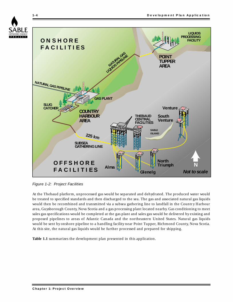
Figure 1-2: Project Facilities
At the Thebaud platform, unprocessed gas would be separated and dehydrated. The produced water wouldbe treated to specified standards and then discharged to the sea. The gas and associated natural gas liquidswould then be recombined and transmitted via a subsea gathering line to landfall in the Country Harbourarea, Guysborough County, Nova Scotia and a gas processing plant located nearby. Gas conditioning to meetsales gas specifications would be completed at the gas plant and sales gas would be delivered by existing andproposed pipelines to areas of Atlantic Canada and the northeastern United States. Natural gas liquidswould be sent by onshore pipeline to a handling facility near Point Tupper, Richmond County, Nova Scotia.At this site, the natural gas liquids would be further processed and prepared for shipping.
Table 1.1 summarizes the development plan presented in this application.
1-4 Development Plan Application
Chapter 1: Project Overview
Venture
SUBSEA GATHERING LINE
SouthVenture
SABLEISLAND
NorthTriumph
GlenelgAlma
225 km
NATURAL GAS PIPELINE
THEBAUDCENTRALFACILITIES
H
SLUGCATCHER
NATURAL GAS
LIQUIDS PIPELINE
Not to scale
LIQUIDSPROCESSING
FACILITY
O F F S H O R EF A C I L I T I E S
O N S H O R EF A C I L I T I E S
POINTTUPPERAREA
COUNTRYHARBOURAREA
GAS PLANT
N

Table 1.1: Current Development Plan Summary
Sales Gas: Plateau Rate: 11.3 E6M3/d
Plateau: 16 years
Life: 25 years minimum
Raw Gas Reserves: 129.3 E9M3 Mean Value
Platforms: Type Site Design Rates
(E3M3/d)
Central Thebaud (Inlet) 6230
Central Thebaud (Six Field) 12750
Satellite Venture 7080
Satellite North Triumph 3680
Wellhead South Venture 1840
Satellite Alma 3680
Satellite Glenelg 3680
Development Wells: Field Number
Thebaud 4
Venture 9
North Triumph 3
South Venture 2
Alma 5
Glenelg 5
Total 28
Offshore Pipelines: Length Diameter Wall Max. Operating
(Km) Thickness Pressure
(mm) (mm) (KPa)
Thebaud - Shore 225 609 15.9 11,725
Venture - Thebaud 56 457 12.7 13,800
North Triumph - Thebaud 35 324 12.7 13,200
South Venture - Venture 5 219 12.7 14,140
Alma - Thebaud 50 324 12.7 13,200
Glenelg - Thebaud 32 324 12.7 13,200
Slugcatcher: Location: Country Harbour Area
Type: Multipipe
Liquid Capacity: 2385 m3
Gas Plant: Location: Country Harbour
Type: Turboexpander /Natural Gas Dewpointing
Products: Sales Gas, NGL mix
NGL Transmission Pipeline: Location: Country Harbour to Point Tupper
Size: 219 mm
Length: 67 km
Wall Thickness: 6.4 mm
Max. Op. Pressure: 6900 KPa
NGL Processing: Location: Point Tupper
Type: Fractionation / Stabilization
Products: LPG Mix, Condensate
Development Plan Application 1-5
Chapter 1: Project Overview

The Project has two main phases:
Initial Development Phase: Development drilling to prepare initial production wellsConstruction of Project facilitiesDevelopment of drilling and construction of facilities for additional production sites
Production Phase: Gas production and processing
As shown in the Project schedule, Figure 1-3, the Proponents intend to make the final decision to proceedin 1997, with gas production from the first phase of the Project by late 1999. Drilling and construction inthe current proposal would start at Thebaud, Venture and North Triumph. During the Production Phase,fields would be developed as required to maintain the sales gas rate of 11.3 million cubic metres per day.Construction at the South Venture, Glenelg and Alma fields is currently planned for 2004-2007. The SableProject is projected to last until the year 2025. Project facilities will be designed so that with proper inspec-tion, maintenance and repairs, they can be used well beyond the current Project life. This enables subse-quent development at existing satellite fields and further exploratory discoveries to be incorporated intothe Project as warranted.
The timing of these Project elements may be adjusted during the life of the Project in order to respond toevolving market conditions and additional information from field and design studies, as well as explorationsuccesses.
Figure 1-3: Proposed Project Schedule
1-6 Development Plan Application
Chapter 1: Project Overview
Stage 1 Preliminary Feasibility Studies Completed
Stage 2 • Public Consultation • Technical/ Environmental/ Pipeline/Market Studies • Prepare and File Application
Stage 3 • Front End Engineering Design (FEED) • Preparation of Bid Packages • Acquire 3D Seismic & Optimize Reservoir Depletion Plans • Hearings • Government Approval • Project Approval by Proponents
Detailed Engineering Design
OFFSHORE DRILLING
CONSTRUCTION
PRODUCTION
DEVELOPMENT DECISION TO BE MADE
INITIAL DEVELOPMENT STAGES
PRODUCTION PHASE
PRE-DEVELOPMENT STAGES
1995 1996 1997 1998 1999 2000

1.3 Project Development Strategy
In offshore development, the Project plan must, at the outset, be flexible to accommodate all likely contin-gencies since unanticipated changes may be costly and are often extremely difficult to accommodate. Thedevelopment approach adopted for this Project relies on the use of multi-disciplinary teams to evolve theProject design as information becomes available.
The current development plan is based on estimates of gas reserves, established primarily from explorationseismic data and current projections of future market conditions. As new seismic data, reanalysis of old dataand new engineering studies become available, the development scheme may be altered in significant ways.For example, the number of wells and/or the sequence of fields may be adjusted during the life of theProject or new discoveries may be added. The plan must have sufficient flexibility to also incorporateadvances in technologies and the integration of more accurate real-time information about winds, wavesand currents in the offshore region. Flexibility in responding to these conditions is a key element in theProject development and will be needed in its ongoing regulation.
As illustrated in Figure 1-4, a wide range of alternatives were considered during the early stages of theProject. In the early 1980’s, Mobil submitted a development proposal for natural gas for the Venture Field.Preliminary studies of other development options, including generating electrical power from the naturalgas, the feasibility of applying Liquid Heavy Gas (LHG) technology, and the potential transportation of gasas a Liquified Natural Gas (LNG) have also been evaluated.
The criteria used in assessing the potential alternatives included the following:
• safety• environmental protection• economic criteria• capital cost and cost uncertainty• operating and maintenance costs• reliability and availability of facilities• complexity of operations• operating flexibility• pipeline route• ease of expansion• Canada - Nova Scotia benefits• regulatory requirements
The following sections of the Development Plan Application identify alternatives that could be incorporat-ed into the Project design during the development phase. These are identified as DevelopmentAlternatives. The application also presents alternatives that preliminary studies indicate are unsuitable, foreconomic, environmental, safety or technological reasons. These are identified as Eliminated Alternatives.
Development Plan Application 1-7
Chapter 1: Project Overview

Figure 1-4: Project Development Process
The Project schedule of activities shown in Figure 1-5 indicates that many activities are being conducted con-currently. Therefore, as information becomes available, the Project scope will continue to be refined. Thisapproach allows the Project team to make increasingly precise decisions about Project options, such as the
1-8 Development Plan Application
Chapter 1: Project Overview
REGULATORS
Operations
Construction
Detail Design
FEED
Engineering Def’n
Reservoir Modelling & Surveillance
3-D
Drilling
Public Consultation
Environmental Assessment
Feasibility
Scoping Studies
Appraisal
Exploration
ALT
ERN
ATI
VES
DEV
ELO
PMEN
T A
LTER
NA
TIVE
S
PREF
ERR
ED
DEV
ELO
PMEN
T
PLA
N APPROVED DEVELOPMENT
PLAN
PRODUCTION LICENCE ABANDONMENTSCOPE
PROJECT SEQUENCE/SCHEDULE
Concept Safety Analysis
Approved
DPA Approval
Dril l ing Program Approved
Production Facil ity Certif icate of Fitness
Approval to Commence Operations
Approval to Abandon
NU
MB
ER
OF
AL
TE
RN
AT
IVE
S

need for further data acquisition or the implementation of new or emerging technologies for the purposeof maximizing reserves recovery. This process of refinement of the Project scope through the integrationof information throughout the development is expected to produce the most responsive and cost-effectivedevelopment plan.
Figure 1-5: Schedule of Project Activities
Development Plan Application 1-9
Chapter 1: Project Overview
1994 1995 1996 1997 1998 1999
Project Appraisal • Eng. studies - Reserves, Deliverability, Market Scoping cost estimates. • Dialogue with Govt. Partners agree to proceed. • Joint Mobil/Shell team. Report in DPA concept format.
Project Implementation • Project AFE approved by partners • EPC contracts placed, • “Alliance” formed, ongoing regulatory approvals • staffing and operations plan implemented • on stream by 1/11/99
Project Acceptance • DPA EIS, SEIS submitted for approval • Proj. Man. contractor selected • Eng. definition performed • AFE and cost estimate prepared • Landsites selected • Staffing and Operations plans made • Regulatory requirements understood • Pre-commitments for drilling
Benefits
DPA
EIS
SEIS
Fiscal Terms Agreed
Design Questionnaire
Bid Rig Mobilize Rigs
Drill WellsConvert & Certify Rigs, Design and Fabricate Templates
Rig Market Survey
Essential Front End AFE
Rig Award
EHSM System Development; Process Safety Analysis, Conceopt Safety Analysis, Hazard Studies, HAZOP Reviews, Contractor Safety, Operating and Maintenance Procedures, Operations and Maintenance Training, Process Safety Information, Pre-Startup Safety Review
�3D Seismic Ops
3D Seismic Interpretation & Reservoir Mapping
Reservoir Characterization
Reservoir Surveillance
Develop Safety Manuals, Contingency Plans and Environmental Protection Plans (Drilling, Onshore Construction, Offshore Construction, Operations)
Evaluate Questionnaire
Approve AFE
Issue Questionnaire
REGULATORSRegulatory Authorities Review of Designs, Constructions and Installations
Approvals for vessels, equipment etc.
Select certifying institution and involve on design, EPC, and regulatory path to certificates of fitness for P/L, Platform and Gas Plants
Engineering Definition, Alliance Structure
Bid EPC's
Rework Eng. with EPC contractors
Cost estimate AFE Prep
Approval to operate Platforms, P/Ls, Gas PlantsSubmit Conditions
Partner Decision
Award PM Contract
FILINGS:
Construction and Installation
Startup & Commission
Detailed Engineering & Fabrication
REGULATORY
ENGINEERING/ CONSTRUCTION
ENVIRONMENT, HEALTH & SAFETY
DRILLING
RESERVOIR MANAGEMENT
Concept Safety Analysis/Evaluation
Drilling EH&S Manuals & Plans
Onshore Construction EH&S Manuals & Plans
Offshore Construction EH&S Manuals & Plans
Operations EH&S Manuals & Plans
Reservoir Modelling
OPER
ATIO
NS
Public and Govt. Consultation • Public and Govt. consultation • DPA, EIS, SEIS, prepared • Fiscal and Commercial terms agreed and approved • Regulatory interfaces defined • Eng. studies, site selection, process definition

1.4 Project Management
1.4.1 Project Management Approach
The Sable Offshore Energy Project management approach relies on the use of multi-disciplinary teams withcommon goals to successfully integrate the knowledge, skills and experience of Project personnel and par-ticipating contractors. Initially, the Project team will consist of employees from the Proponent’s companiesand the selected engineering contractor(s). The use of multi-disciplinary teams allows for better integra-tion of information in the refinement of Project design which results in shorter time between discovery togas sales. As production facilities are better matched to the expected reservoir potential, investment isoptimized. During Front End Engineering Design (FEED), the team will also seek the participation of spe-cialists in environmental engineering, hazard and risk analysis, drilling, construction, and other areas.Specialists in these areas will assure standards of health, safety and environmental protection are main-tained.
Following Project approval and the decision to proceed, the current plan envisages operations conductedthrough a single entity, such as an operating company or a joint venture. The successful history of joint ven-tures in the petroleum industry will provide experience and direction in developing sound managementstructure and effective, incentive-based relationships with contractors.
1.4.2 Project Principles and Guidelines
The Sable Offshore Energy Project is a complex undertaking, involving five Project participants, many con-tractors and suppliers, and hundreds of individuals. In order to provide common guidance to all of the peo-ple involved, the Proponents have established a set of Project Principles as shown in Figure 1-6. The prin-ciples address four major areas:
• Business Principles• Responsible Development Principles• Compensation and Benefits• Project Ethics
1-10 Development Plan Application
Chapter 1: Project Overview
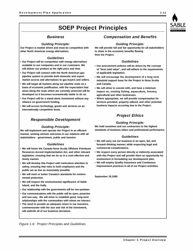
Figure 1-6: Project Principles and Guidelines
Development Plan Application 1-11
Chapter 1: Project Overview
Business
Guiding Principle:Our Project is market driven and must be competitive withother North American energy alternatives.
Guidelines• Our Project will be competitive with energy alternatives
available to our companies and to our customers. We will deliver our product at the right price and time.
• Our Project will connect with the North American gaspipeline system to provide both domestic and export market access and alternatives to gas buyers and sellers.
• We will target all markets along our pipeline route on abasis of economic justification, with the expectation thatareas along the route which are currently unserved will bedeveloped as it becomes economically viable to do so.
• Our Project will be a stand-alone investment without anyreliance on government funding.
• We will access technology, goods and services on aninternationally competitive basis.
Responsible Development
Guiding Principle:We will implement and operate the Project in an efficientmanner, seeking win/win outcomes in our relations with allstakeholders - government, public and investor.
Guidelines• We will honor the Canada-Nova Scotia Offshore Petroleum
Resources Accord Implementation Act, and other relevantlegislation, ensuring that we do so in a cost-effective andtimely manner.
• We will develop this Project with meticulous attention tosafety, ensuring that risks to both employees and the public are as low as reasonably possible.
• We will meet or better Canada’s standards for environ-mental protection.
• We will respect the environmental significance of SableIsland, and the Gully.
• Our relationship with the governments will be non-partisan.
• Our communications with the public will be open, proactiveand two-way. We will strive to establish good, long-termrelationships with the communities with whom we interact.
• The need to provide an adequate return to our investors,commensurate with the size and risk of the investment,will underlie all of our business decisions.
Compensation and Benefits
Guiding Principle:We will provide full and fair opportunity for all stakeholdersto share in the economic benefits flowing from the Project.
Guidelines• Our procurement policies will be driven by the concept
of “best total value”, and will adhere to the requirementsof applicable legislation.
• We will encourage the development of a long termindustrial support base for the Project in Nova Scotia and Canada.
• We will strive to coexist with, and have a minimum impact on, existing fishing, aquaculture, forestry, agricultural and other businesses.
• Where appropriate, we will provide compensation for services provided, property utilized, and other potentialbusiness impacts occurring due to the Project.
Project Ethics
Guiding Principle:We hold ourselves and our contractors to the highest standards of business ethics and professional performance.
Guidelines• We will carry out our business in an open, fair, and
forward-thinking manner, while respecting legal and commercial considerations.
• We respect every person directly or indirectly associatedwith this Project and will provide them an opportunity forinvolvement in formulating our development plan.
• We will employ Quality Assurance and ContinuousImprovement practices in all of our Project activities.
September 19,1995
SOEP Project Principles

1.4.3 Proponent’s Experience
Mobil and Shell are providing technical, business, safety and environmental leadership to the Project’s engi-neering and management team. Substantial work was completed for the proposed Venture Project in the1980’s, much of which is incorporated into the development plan for the Sable Offshore Energy Project.The Proponents have also drawn upon their considerable experience though their international affiliatesin offshore developments in the North Sea and the Gulf of Mexico.
Mobil and its affiliates produce 48 billion cubic metres of natural gas per year worldwide. Shell and its affil-iates produce 71 billion cubic metres annually, much of this from wells in the Gulf of Mexico where the dailyproduction rate is three times that planned for the Sable Offshore Energy Project.
Shell’s development of deep water as well as shallow water gas resources in the Gulf region has requiredtechnological innovations in drilling and production operations that may be adapted to the shallow waterSable fields. Mobil is also a leader in offshore development on a global scale. In Mobile Bay, an environ-mentally sensitive area of the Gulf Coast, Mobil has successfully operated for a decade using productionfacilities similar to those proposed for the Sable Project. Mobil also has extensive experience usingunmanned platform facilities more than 100 km offshore in the North Sea. The use of satellite technolo-gy, unmanned platforms and jack-up rigs are expected to increase the cost-effectiveness and safety of theSable Offshore Energy Project. The North Sea experiences provide a source of information about a north-ern climate comparable to the waters offshore Nova Scotia.
1.5 REGULATORY OVERVIEW
A number of regulatory authorities are responsible for representing the interests of the people of NovaScotia and Canada in the management of natural resources. These interests include the equitable access tonatural gas and other resources, protection of the environment, and sharing of the economic benefit fromthe production of natural resources via economic activity and through the collection of royalties and tax rev-enues. This submission addresses regulatory guidelines based on energy policy established in key legislation.
Primary Legislation
The Sable Offshore Energy Project will be regulated by a number of federal and provincial agencies.Relevant legislation includes:
• Canada - Nova Scotia Offshore Petroleum Resources Accord Implementation Act• Canada - Nova Scotia Offshore Petroleum Resources Accord Implementation (Nova
Scotia) Act; (these two acts are jointly known as the Accord Acts)• National Energy Board Act• Nova Scotia Energy and Mineral Resources Conservation Act• Nova Scotia Pipeline Act.
1-12 Development Plan Application
Chapter 1: Project Overview

The following three agencies have indicated that they are the responsible regulatory authorities for regu-lating various aspects of the Project:
• Canada - Nova Scotia Offshore Petroleum Board• National Energy Board• Nova Scotia Energy and Mineral Resources Conservation Board
These agencies are developing a coordinated regulatory process for a collaborative approach to the effec-tive and efficient regulation of the Project.
Environmental Review
Several government departments and agencies have indicated they are responsible for review of theProject’s environmental and socio-economic impacts:
• Canadian Environmental Assessment Agency• Natural Resources Canada• Nova Scotia Department of the Environment• Nova Scotia Department of Natural Resources• National Energy Board• Canada-Nova Scotia Offshore Petroleum Board
In order to coordinate their efforts, these agencies are developing a Memorandum of Understanding tocarry out joint environmental assessment reviews of the Sable Offshore Energy Project. A five memberpanel is anticipated to be appointed to hold public hearings for the Sable Project and to prepare a reportwith recommendations to the responsible government agencies.
Development Plan Application 1-13
Chapter 1: Project Overview