Embed Size (px)
Citation preview
Slide # 1 of
Execution and Return on Investment of
Reliability CenteredMaintenance
Slide # 2 of
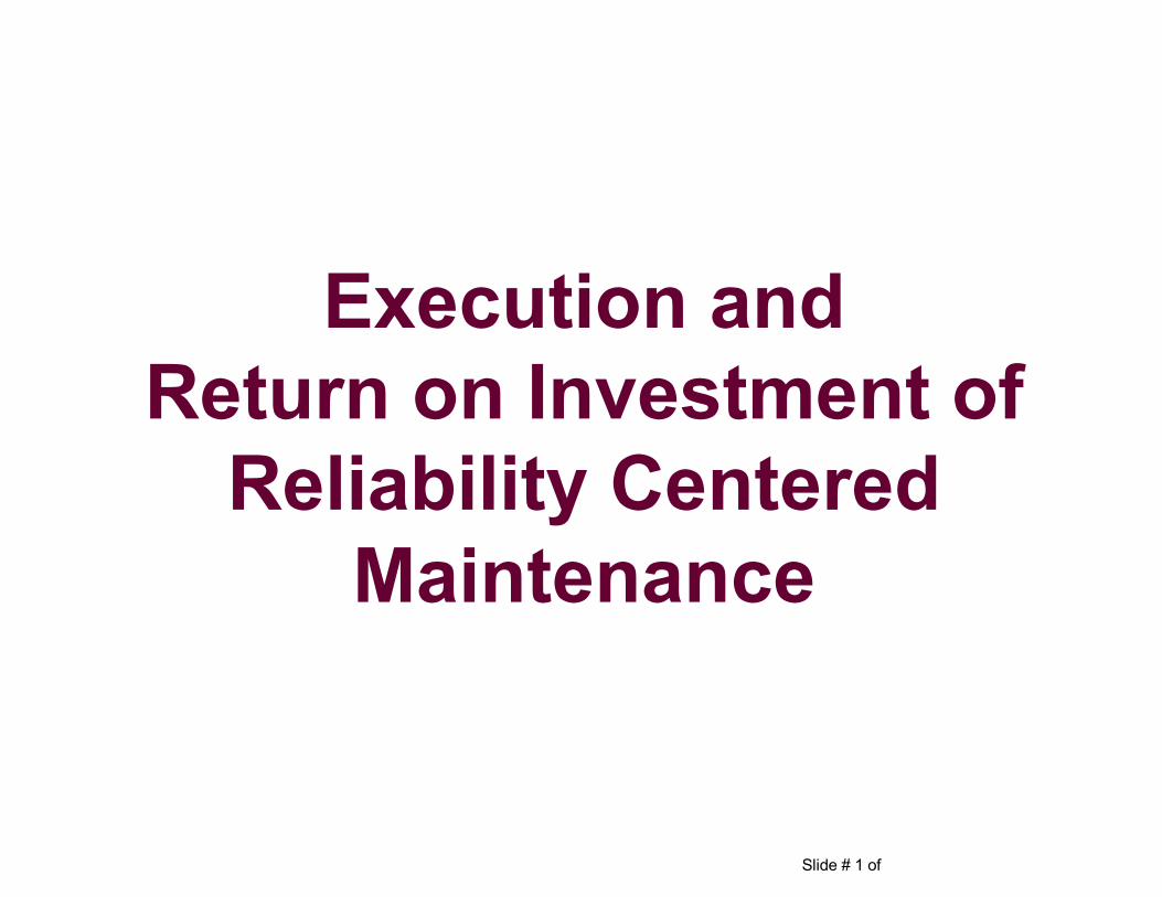
1. What is RCM?2. Steps to Successfully Implement an RCM Program 3. Case Studies4. Cost Benefits and Return on Investment (ROI)
PURPOSE: Reliability Centered Maintenance (RCM) is more than a predictive maintenance program. This session will explore the use of RCM and Condition Based Monitoring (CBM) in the facility maintenance program and describe how to employ an RCM program. Attendees will take away an understanding of maintenance techniques used in RCM, how CBM techniques can simplify and reduce cost in a maintenance program, and the tangible benefits of RCM.
Reliability Centered Maintenance
Slide # 3 of
What is RCM?
Reliability Centered Maintenance
Slide # 4 of
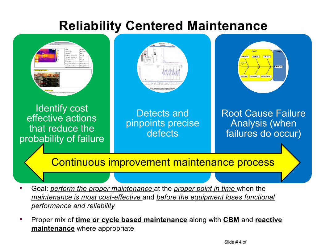
• Goal: perform the proper maintenance at the proper point in time when the maintenance is most cost-effective and before the equipment loses functional performance and reliability
• Proper mix of time or cycle based maintenance along with CBM and reactive maintenance where appropriate
Reliability Centered Maintenance
Identify cost effective actions that reduce the
probability of failure
Detects and pinpoints precise
defects
Root Cause Failure Analysis (when
failures do occur)
Continuous improvement maintenance process
Slide # 5 of
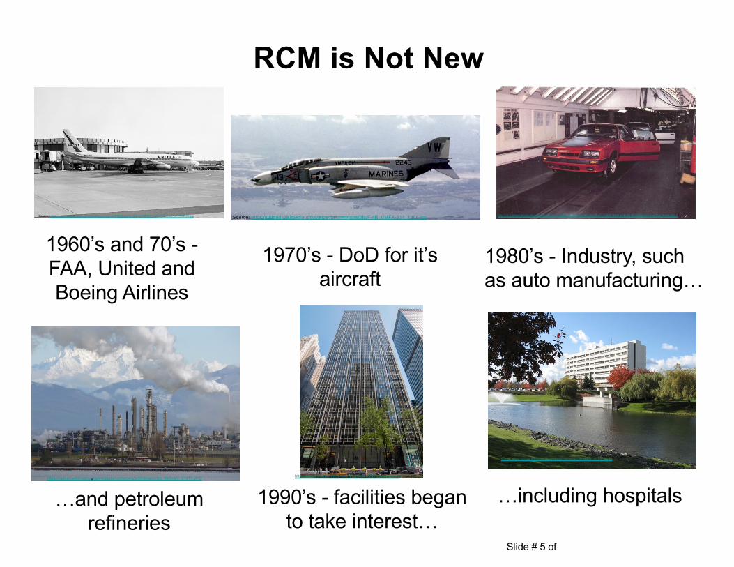
1970’s - DoD for it’s aircraft
RCM is Not New
1960’s and 70’s -FAA, United and Boeing Airlines
1980’s - Industry, such as auto manufacturing…
1990’s - facilities began to take interest…
…and petroleum refineries
…including hospitals
Source: https://upload.wikimedia.org/wikipedia/commons/3/36/Douglas_DC-8-11%2C_United_Airlines_JP7765489.jpg Source: https://upload.wikimedia.org/wikipedia/commons/f/fc/F-4B_VMFA-314_1968.jpg http://vb.foureyedpride.com/showthread.php?104442-and-on-the-8th-day-God-created-the-Fox-Body-Mustang-and-saw-that-it-was-good!!
https://upload.wikimedia.org/wikipedia/commons/5/51/Anacortes_Refinery_31911.JPG http://www.fisherbrothers.com/properties/299-park-avenue
Source: https://upload.wikimedia.org/wikipedia/commons/9/9d/MAMC_in_the_fall.jpg
Slide # 6 of
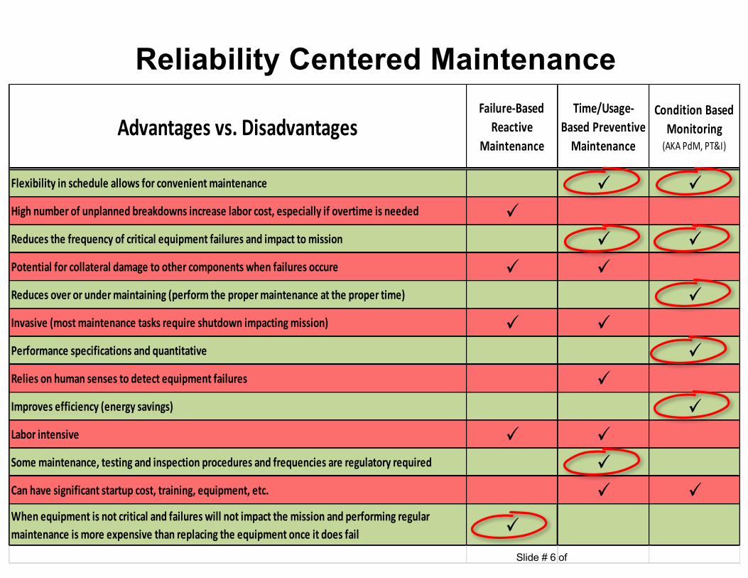
Reliability Centered Maintenance
Advantagesvs.DisadvantagesFailure-Based
ReactiveMaintenance
Time/Usage-BasedPreventiveMaintenance
ConditionBasedMonitoring(AKAPdM,PT&I)
Flexibilityinscheduleallowsforconvenientmaintenance ü üHighnumberofunplannedbreakdownsincreaselaborcost,especiallyifovertimeisneeded üReducesthefrequencyofcriticalequipmentfailuresandimpacttomission ü üPotentialforcollateraldamagetoothercomponentswhenfailuresoccure ü üReducesoverorundermaintaining(performthepropermaintenanceatthepropertime) üInvasive(mostmaintenancetasksrequireshutdownimpactingmission) ü üPerformancespecificationsandquantitative üReliesonhumansensestodetectequipmentfailures üImprovesefficiency(energysavings) üLaborintensive ü üSomemaintenance,testingandinspectionproceduresandfrequenciesareregulatoryrequired üCanhavesignificantstartupcost,training,equipment,etc. ü üWhenequipmentisnotcriticalandfailureswillnotimpactthemissionandperformingregularmaintenanceismoreexpensivethanreplacingtheequipmentonceitdoesfail ü
Slide # 7 of
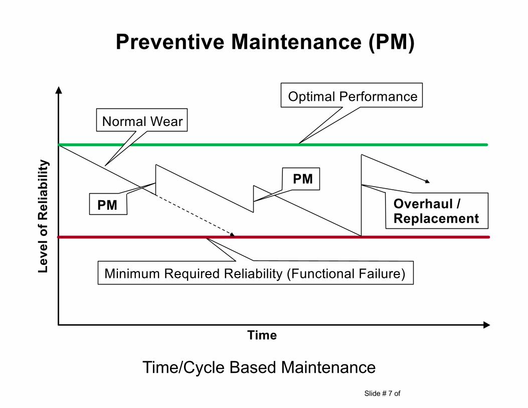
Preventive Maintenance (PM)
Time
Leve
l of R
elia
bilit
y
Optimal Performance
Minimum Required Reliability (Functional Failure)
Normal Wear
Overhaul / Replacement
PM
PM
Time/Cycle Based Maintenance
Slide # 8 of
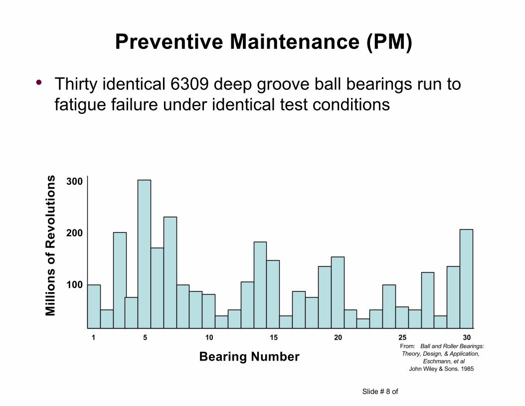
• Thirty identical 6309 deep groove ball bearings run to fatigue failure under identical test conditions
300
1 5 10 15 20 25 30
Bearing Number
200
100
Mill
ions
of R
evol
utio
ns
From: Ball and Roller Bearings:Theory, Design, & Application,
Eschmann, et alJohn Wiley & Sons. 1985
Preventive Maintenance (PM)
Slide # 9 of
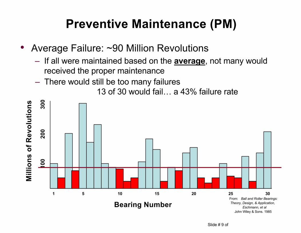
• Average Failure: ~90 Million Revolutions– If all were maintained based on the average, not many would
received the proper maintenance
300
1 5 10 15 20 25 30
Bearing Number
200
100
Mill
ions
of R
evol
utio
ns
From: Ball and Roller Bearings:Theory, Design, & Application,
Eschmann, et alJohn Wiley & Sons. 1985
– There would still be too many failures13 of 30 would fail… a 43% failure rate
Preventive Maintenance (PM)
Slide # 10 of
300
1 5 10 15 20 25 30
Bearing Number
200
100
Mill
ions
of R
evol
utio
ns
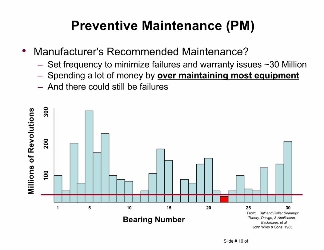
• Manufacturer's Recommended Maintenance?
From: Ball and Roller Bearings:Theory, Design, & Application,
Eschmann, et alJohn Wiley & Sons. 1985
Preventive Maintenance (PM)
– Set frequency to minimize failures and warranty issues ~30 Million– Spending a lot of money by over maintaining most equipment– And there could still be failures
Slide # 11 of
• Condition Based Maintenance (CBM)– Also Known As:
• Predictive Maintenance (PdM)• Predictive Testing & Inspection (PT&I)• Condition Monitoring (CM)
– Is the process of monitoring machinery parameters that are indicative of developing failure
– The real purpose of CBM is to assist in the identification and elimination of the root cause of machinery defects
Note: We prefer not to use the term “Predictive” as it implies we can “predict” when something will fail. All we can really do is monitor condition and detect when a failure (defect) begins and the severity of the defect before it fails. And then perform the proper maintenance at the proper point in time when the maintenance is most cost-effective and least disruptive before the equipment loses performance and reliability
Condition Based Monitoring (CBM)
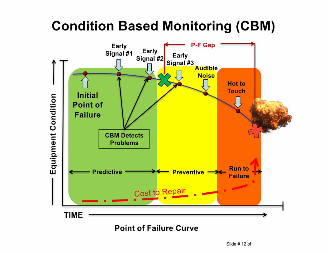
Slide # 12 of
Condition Based Monitoring (CBM)
Equi
pmen
t Con
ditio
n
TIME
Initial Point of Failure
Early Signal #2
Early Signal #1 Early
Signal #3Audible Noise
Hot to Touch
CBM Detects Problems
Predictive Preventive Run to Failure
P-F Gap
Point of Failure Curve
Slide # 13 of
• Most common CBM technologies– Vibration Analysis
– Infrared Thermography
– Ultrasonic
– Tribology (Oil & Wear Particle Analysis)
– Motor Current Analysis
Condition Based Monitoring (CBM)
Slide # 14 of
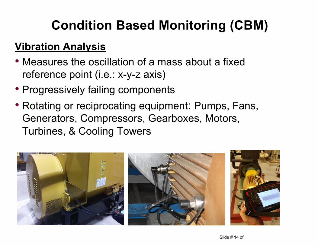
Condition Based Monitoring (CBM)Vibration Analysis• Measures the oscillation of a mass about a fixed
reference point (i.e.: x-y-z axis)• Progressively failing components• Rotating or reciprocating equipment: Pumps, Fans,
Generators, Compressors, Gearboxes, Motors, Turbines, & Cooling Towers
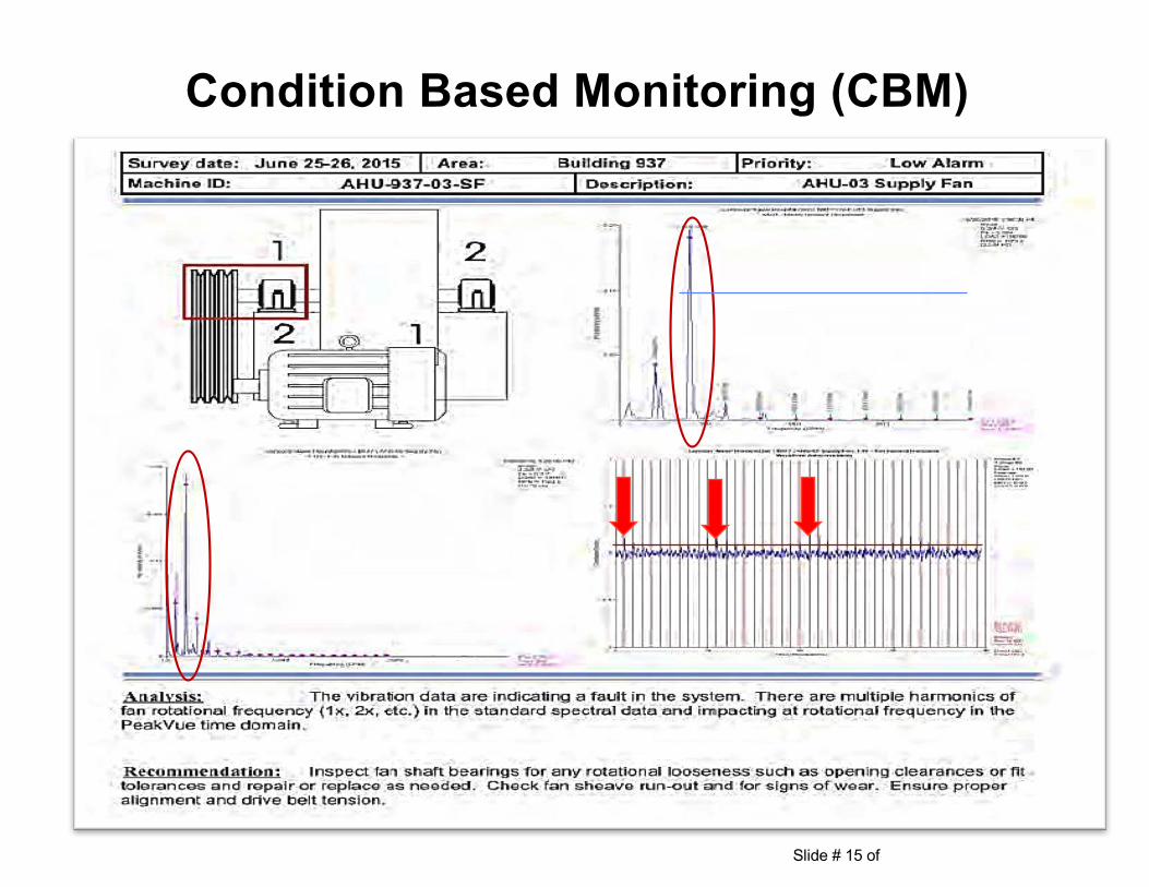
Slide # 15 of
Condition Based Monitoring (CBM)
Slide # 16 of
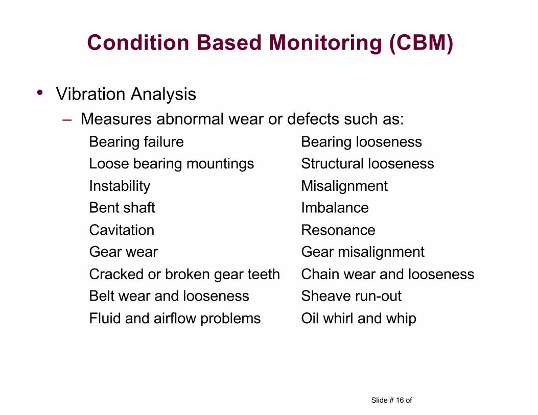
• Vibration Analysis– Measures abnormal wear or defects such as:
Bearing failure Bearing loosenessLoose bearing mountings Structural looseness Instability MisalignmentBent shaft Imbalance Cavitation Resonance Gear wear Gear misalignmentCracked or broken gear teeth Chain wear and loosenessBelt wear and looseness Sheave run-outFluid and airflow problems Oil whirl and whip
Condition Based Monitoring (CBM)
Slide # 17 of
Condition Based Monitoring (CBM)
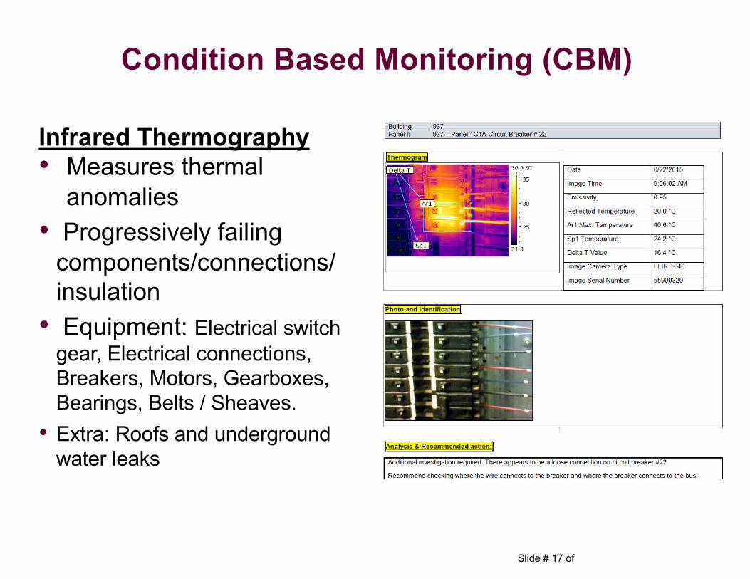
Infrared Thermography• Measures thermal
anomalies• Progressively failing
components/connections/ insulation
• Equipment: Electrical switch gear, Electrical connections, Breakers, Motors, Gearboxes, Bearings, Belts / Sheaves.
• Extra: Roofs and underground water leaks
Slide # 18 of
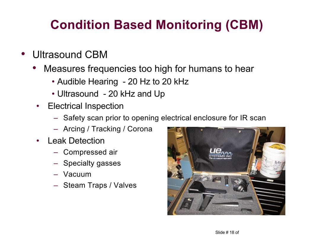
• Ultrasound CBM • Measures frequencies too high for humans to hear
• Audible Hearing - 20 Hz to 20 kHz• Ultrasound - 20 kHz and Up
• Electrical Inspection– Safety scan prior to opening electrical enclosure for IR scan– Arcing / Tracking / Corona
• Leak Detection– Compressed air– Specialty gasses– Vacuum– Steam Traps / Valves
Condition Based Monitoring (CBM)
Slide # 19 of
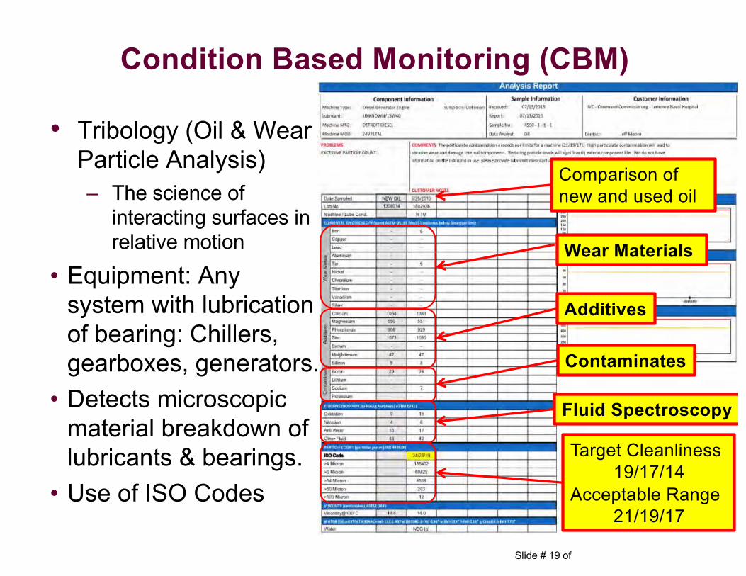
• Tribology (Oil & Wear Particle Analysis)– The science of
interacting surfaces in relative motion
• Equipment: Any system with lubrication of bearing: Chillers, gearboxes, generators.
• Detects microscopic material breakdown of lubricants & bearings.
• Use of ISO Codes
Condition Based Monitoring (CBM)
Target Cleanliness 19/17/14
Acceptable Range21/19/17
Additives
Comparison of new and used oil
Wear Materials
Contaminates
Fluid Spectroscopy
Slide # 20 of
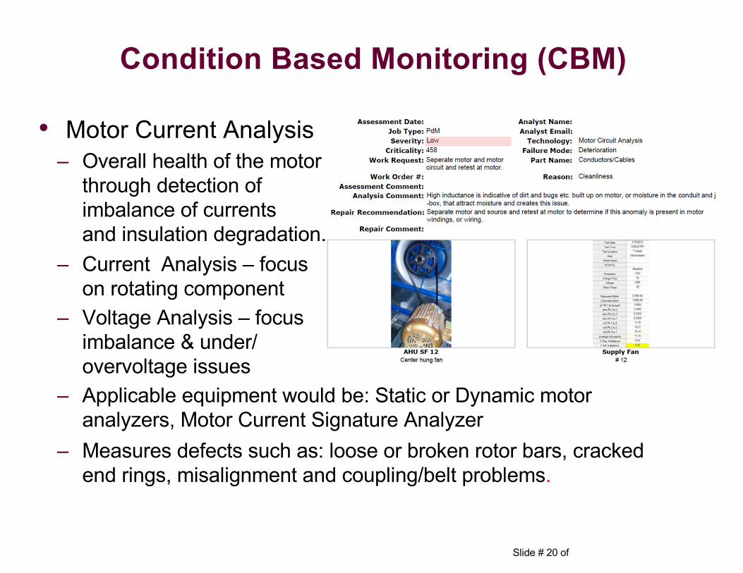
• Motor Current Analysis – Overall health of the motor
through detection of imbalance of currents and insulation degradation.
– Current Analysis – focus on rotating component
– Voltage Analysis – focus imbalance & under/ overvoltage issues
– Applicable equipment would be: Static or Dynamic motor analyzers, Motor Current Signature Analyzer
– Measures defects such as: loose or broken rotor bars, cracked end rings, misalignment and coupling/belt problems.
Condition Based Monitoring (CBM)
Slide # 21 of
Steps to Successfully Implement an RCM Program
Reliability Centered Maintenance
Slide # 22 of
Step# 1: Identification of equipment that will be included in the RCM program
– Typically included are:• Rotating equipment
• Boilers
• Steam reducing stations
• Main electrical switchgear
• Electrical panels serving the life safety, critical and the equipment branches of the emergency power system
• All electrical equipment serving the selected equipment
Implementation Process
Slide # 23 of
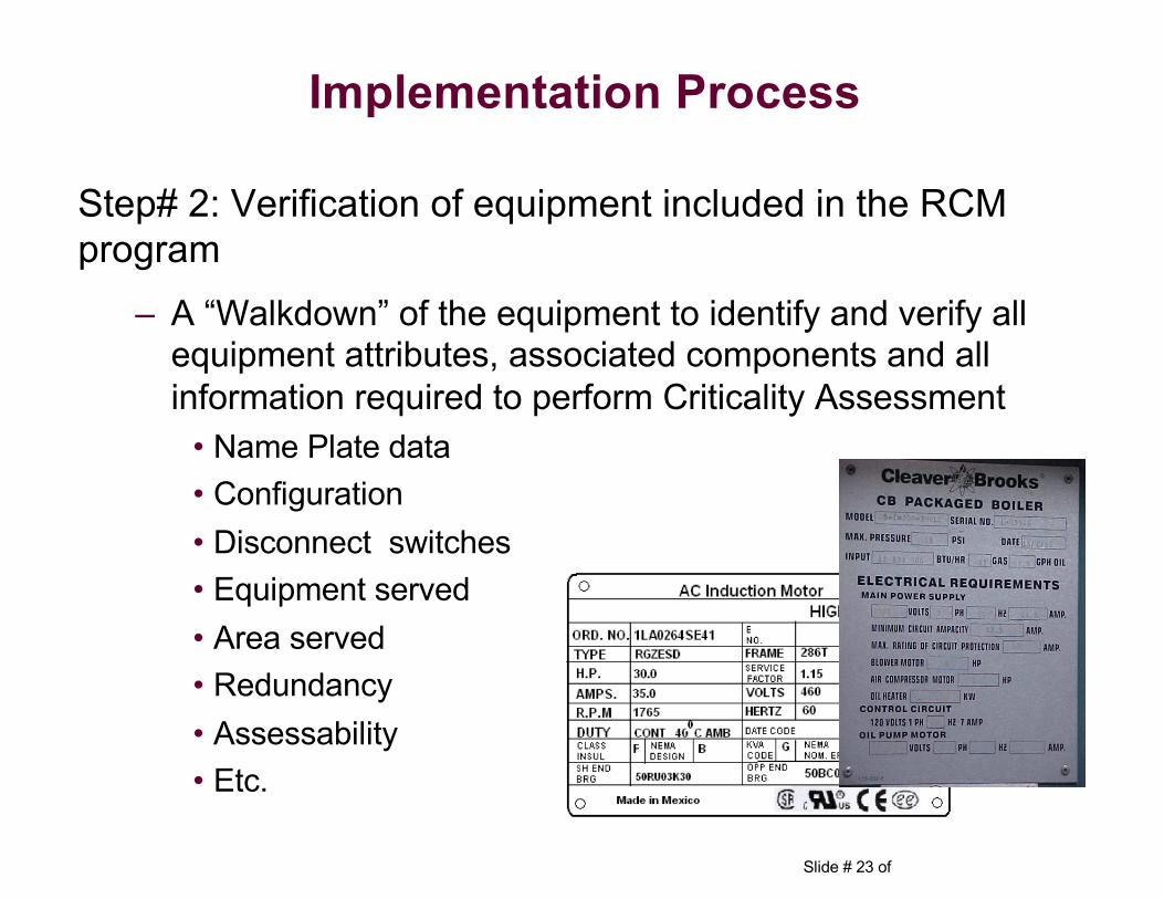
Step# 2: Verification of equipment included in the RCM program
– A “Walkdown” of the equipment to identify and verify all equipment attributes, associated components and all information required to perform Criticality Assessment
• Name Plate data• Configuration• Disconnect switches• Equipment served• Area served• Redundancy• Assessability• Etc.
Implementation Process
Slide # 24 of
Step# 3: Conduct a Criticality Assessment of equipment to determine the relative ranking of items in a system to determine which items get preferential treatment with respect to resource allocation
Implementation Process
Slide # 25 of
Step# 4: Determine failure modes for critical systems, equipment and components (including peripherals)
Implementation Process
Slide # 26 of
Step# 5: Develop an Enhanced Maintenance Plan (EMP) to improve the efficiency and effectiveness of maintenance operations
‒ Identify the proper mix of:ü Time or cycle based maintenance
ü CBM
ü Reactive maintenance where appropriate
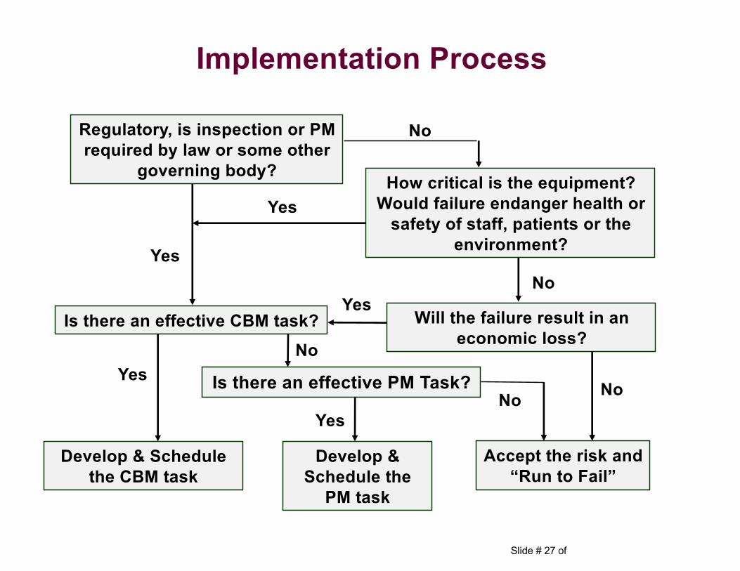
‒ RCM Logic Tree
Implementation Process
Slide # 27 of
Yes
No
Implementation Process
How critical is the equipment? Would failure endanger health or
safety of staff, patients or the environment?
No
Accept the risk and “Run to Fail”
No
Is there an effective CBM task?
Yes
Yes
Develop & Schedule the CBM task
Yes
Develop & Schedule the
PM task
Is there an effective PM Task?
Yes
No
Regulatory, is inspection or PM required by law or some other
governing body?
Will the failure result in an economic loss?
No
Slide # 28 of
Step# 6: Perform a Baseline, using CBM‒ Typical current conditions don’t allow for safe and/or proper
maintenance access to equipment while running• Typical PMs require equipment to be shut down
• CBM requires equipment to be running
• Modifications need to be made
Implementation Process
Slide # 29 of
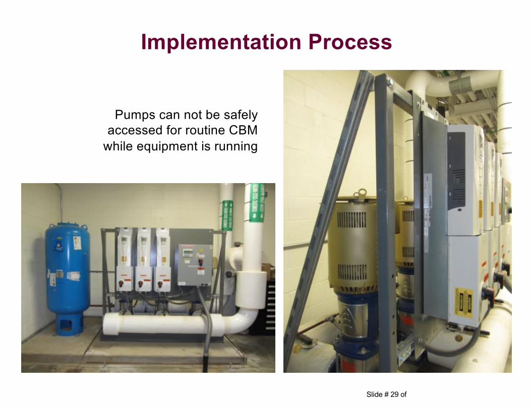
Pumps can not be safely accessed for routine CBM
while equipment is running
Implementation Process
Slide # 30 of
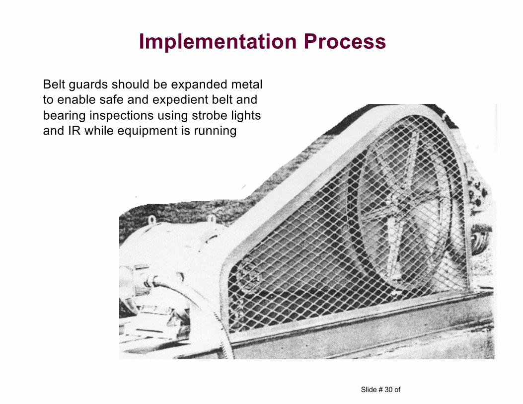
Belt guards should be expanded metal to enable safe and expedient belt and bearing inspections using strobe lights and IR while equipment is running
Implementation Process
Slide # 31 of
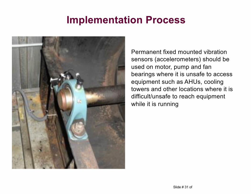
Permanent fixed mounted vibration sensors (accelerometers) should be used on motor, pump and fan bearings where it is unsafe to access equipment such as AHUs, cooling towers and other locations where it is difficult/unsafe to reach equipment while it is running
Implementation Process
Slide # 32 of
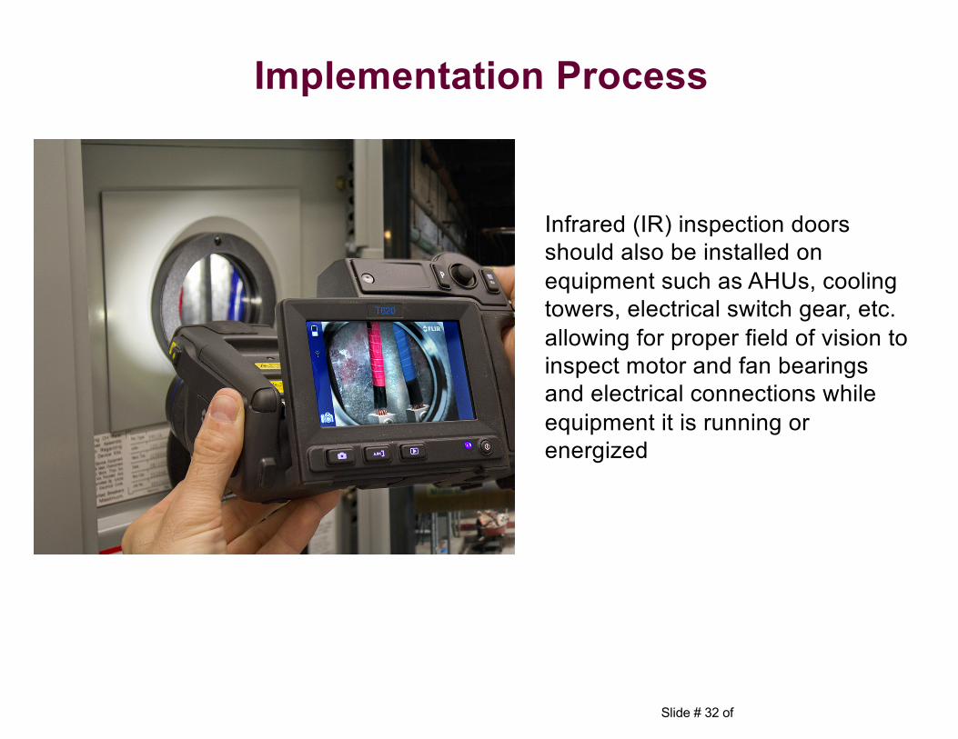
Infrared (IR) inspection doors should also be installed on equipment such as AHUs, cooling towers, electrical switch gear, etc. allowing for proper field of vision to inspect motor and fan bearings and electrical connections while equipment it is running or energized
Implementation Process
Slide # 33 of
Step# 2: A “Walkdown” of the included equipment to identify and verify all equipment attribute data such as:
Implementation Process
Slide # 34 of
Step# 6: Perform a Baseline, using CBM‒ Typical current conditions don’t allow for safe and/or proper
maintenance access to equipment while running• Typical PMs require equipment to be shut down
• CBM requires equipment to be running
• Modifications need to be made
‒ Equipment not installed to precision standards
Implementation Process
Slide # 35 of
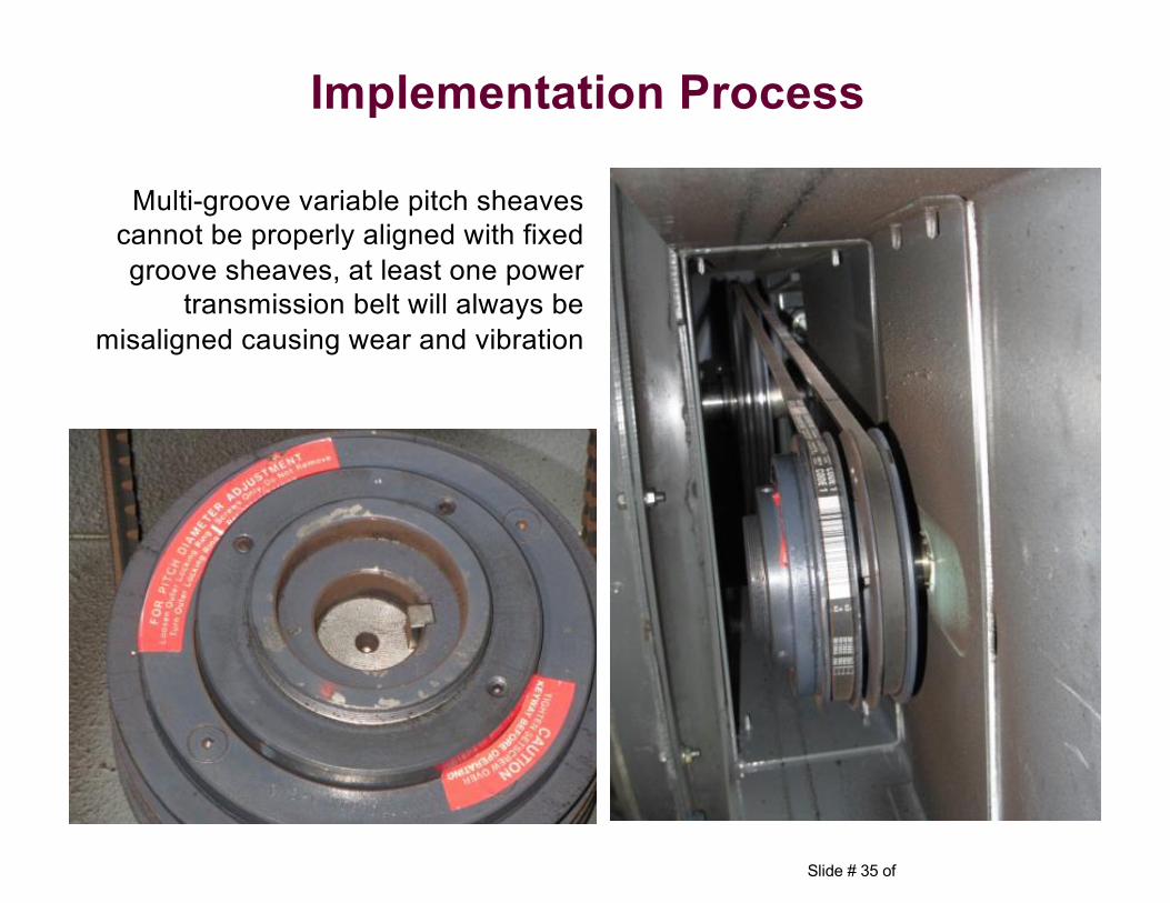
Multi-groove variable pitch sheaves cannot be properly aligned with fixed groove sheaves, at least one power
transmission belt will always be misaligned causing wear and vibration
Implementation Process
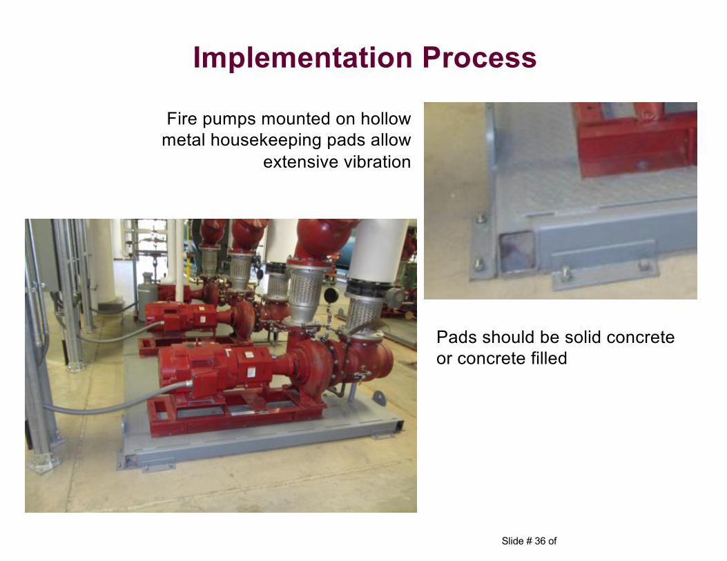
Slide # 36 of
Pads should be solid concrete or concrete filled
Fire pumps mounted on hollow metal housekeeping pads allow
extensive vibration
Implementation Process
Slide # 37 of
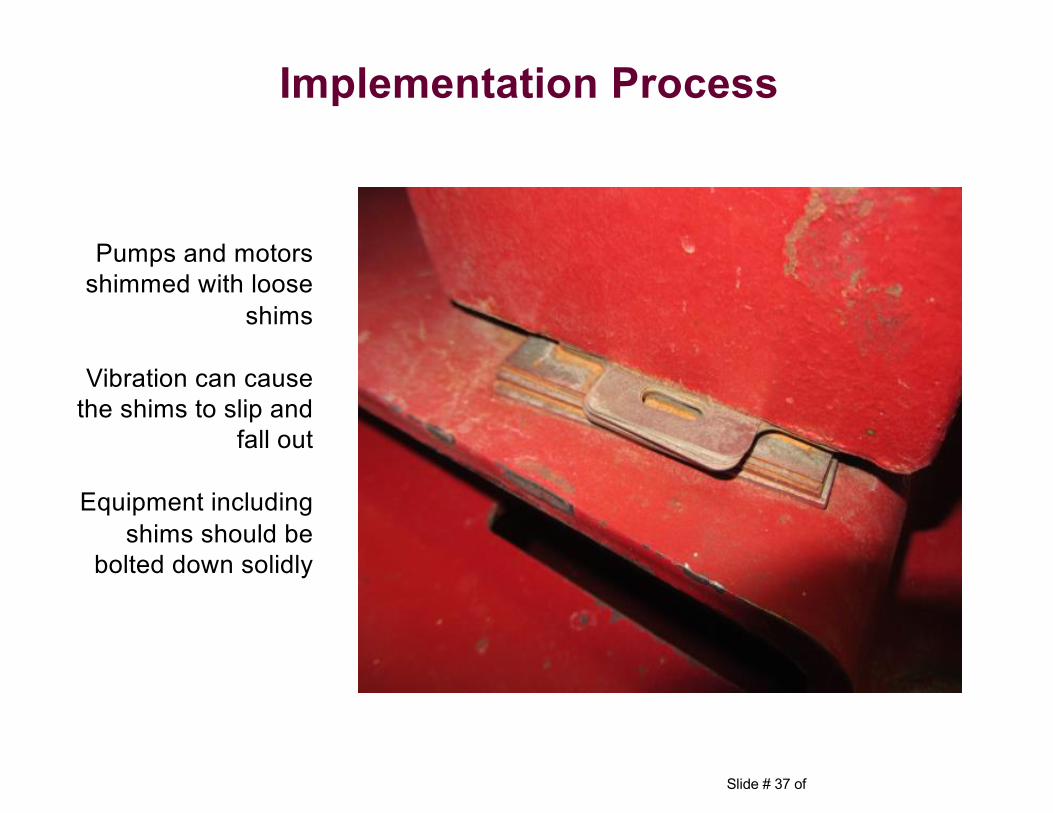
Pumps and motors shimmed with loose
shims
Vibration can cause the shims to slip and
fall out
Equipment including shims should be
bolted down solidly
Implementation Process
Slide # 38 of
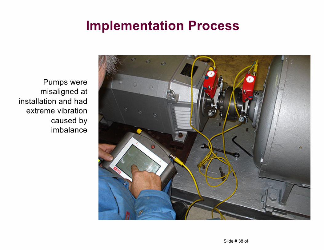
Pumps were misaligned at
installation and had extreme vibration
caused by imbalance
Implementation Process
Slide # 39 of
Step# 6: Perform a Baseline, using CBM– These are just a small sample of typical current conditions– None of these items prevented the equipment from meeting
performance criteria as specified in the construction / project contracts
– All of the items have a significant impact on performance of maintenance and the life expectancy of the equipment
– Up until now, these conditions were considered acceptable• RCM Purchasing Specifications were developed to address
these issues • Includes Receipt Inspections, Installation Specifications,
Testing and Commissioning Recommendations
Implementation Process
Slide # 40 of
Step# 7: Preventive Maintenance Optimization (PMO) gap analysis
– PM tasks are created or re-engineered to target specific failure modes
– PM tasks that do not meet at least one of the following criteria are eliminated
• Prevent a failure mode from occurring• Detect failure modes once they have occurred• PM tasks that are statutory or regulatory in nature
– CBM technology is used when there is an effective task available to WARN when equipment reaches a predetermined condition “Potential Failure Point” allowing time to schedule maintenance PRIOR to reaching “Functional Failure”
– Run-To-Failure• Equipment failure does not have a detrimental effect on operations• Equipment is not expensive and is readily available
Implementation Process
Slide # 41 of
Case Studies
Reliability Centered Maintenance
Slide # 42 of
Case Studies
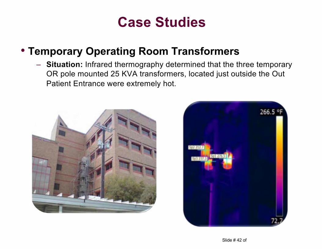
• Temporary Operating Room Transformers– Situation: Infrared thermography determined that the three temporary
OR pole mounted 25 KVA transformers, located just outside the Out Patient Entrance were extremely hot.
Slide # 43 of
Case Studies
• Temporary Operating Room Transformers
– Investigation: The transformers were installed to provide power to a temporary operating room during the Hospital renovation. The investigation revealed that the actual load was much higher than anticipated and 25KVA transformers were insufficient size to carry the load. As a result of the high temperatures, the transformer had begun to leak. The transformers were replaced with three (3) new 75KVA Transformers.
– Conclusion: Avoided an uncontrolled shutdown of the temporary ORs and potential impact to patient care. Avoided a potential burn hazard to personnel entering the clinic, from the oil of the overheated transformers.
Slide # 44 of
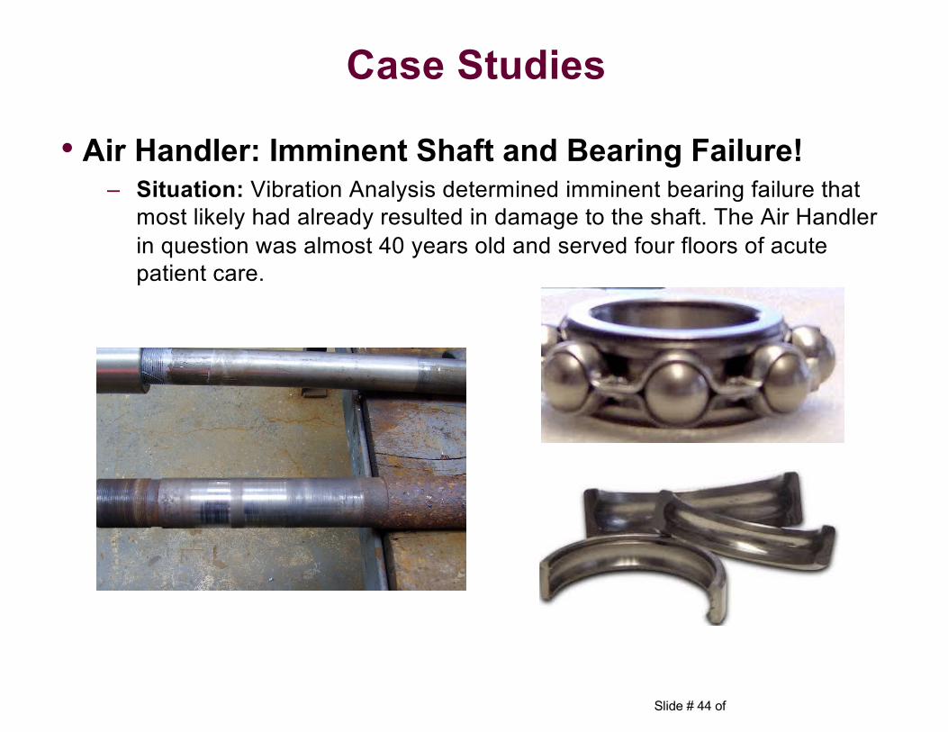
Case Studies
• Air Handler: Imminent Shaft and Bearing Failure!– Situation: Vibration Analysis determined imminent bearing failure that
most likely had already resulted in damage to the shaft. The Air Handler in question was almost 40 years old and served four floors of acute patient care.
Slide # 45 of
• Air Handler: Imminent Shaft and Bearing Failure!
– Investigation: During a scheduled off hour shut down the bearing and shaft were inspected and confirmed to be compromised and in need of immediate replacement. Prior to the scheduled shut down all parts were ordered and made available. The shaft and bearings were replaced during the scheduled shut down and the unit was put back into service in approximately eight hours.
– Conclusion: Avoided an uncontrolled catastrophic failure of an Air Handler serving direct patient care. This type of uncontrolled failure would directly impact patient care for an undetermined amount of time verses a scheduled shut down.
Case Studies
Slide # 46 of
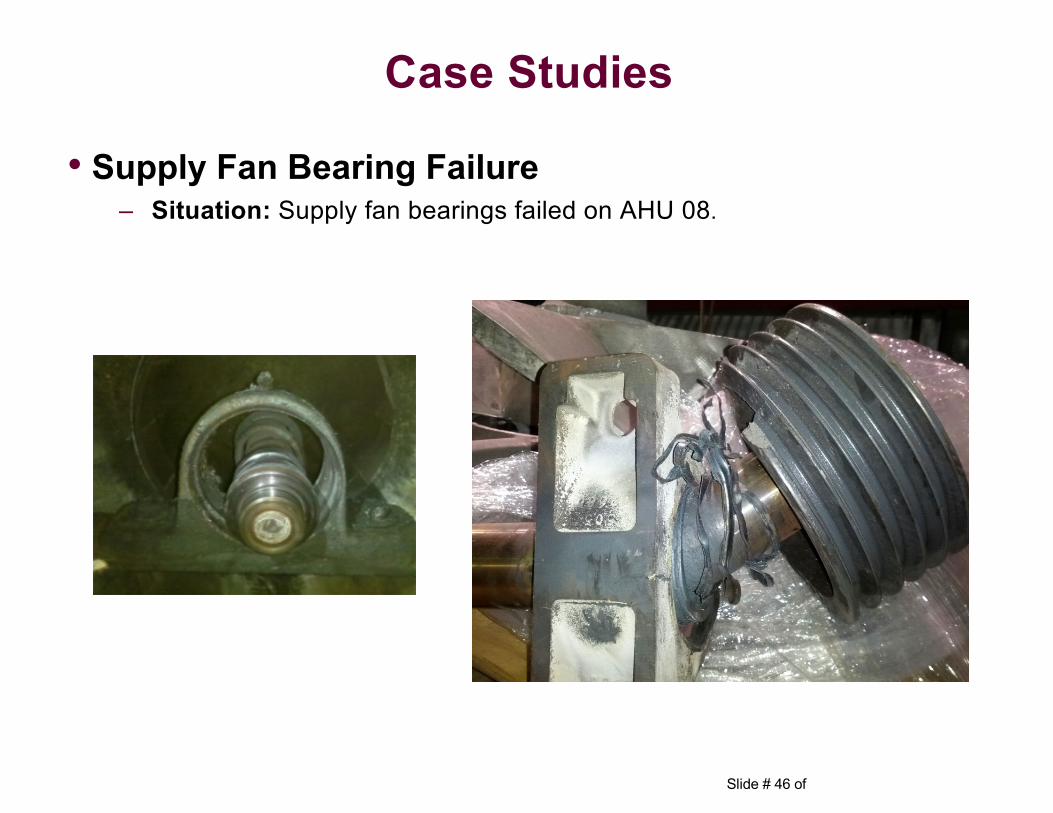
Case Studies
• Supply Fan Bearing Failure– Situation: Supply fan bearings failed on AHU 08.
Slide # 47 of
• Supply Fan Bearing Failure
– Investigation: It was determined that AHU #8 supply fan drive end bearing failed. The fan belts smoked and bearing grease burned, sending smoke into Labor and Delivery. L&D was unavailable for approximately 5 days due to delays in getting parts and the time required to make the repairs. It had previously been determined that due to the configuration of the AHU, bearing vibration readings could not be safely taken with the fan in operation. Action was in progress to purchase and install remote sensors to allow for remote vibration monitoring.
– Conclusion: This event and the lost capabilities in L&D would have been avoided had remote sensors been available to support vibration monitoring.
Case Studies
Slide # 48 of
Case Studies
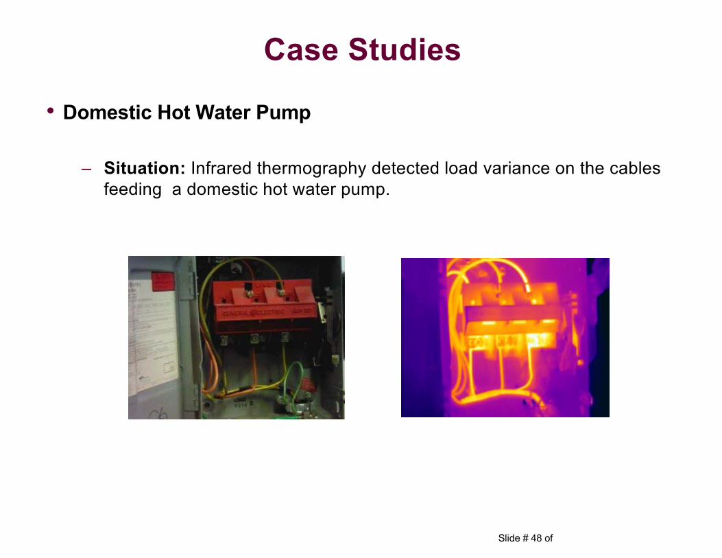
• Domestic Hot Water Pump
– Situation: Infrared thermography detected load variance on the cables feeding a domestic hot water pump.
Slide # 49 of
• Domestic Hot Water Pump
– Investigation: Determined that cable wiring splices were unacceptable and the original wiring to the disconnect was aluminum and the wiring was breaking down. Replaced the wiring with copper.
– Conclusion: Avoided unplanned interruption of domestic hot water to – Outpatient Clinics. Potential avoidance of a fire or interruption Patient
care in the outpatient clinics.
Case Studies
Slide # 50 of
• Chilled Water Pump
– Situation: Vibration analysis identified excessive vibration in the #3 chilled water pump bearings.
– Investigation: The chilled water pump and motor is part of the new central energy plant. It was determined that the pump inboard bearing was defective and that the pump and motor foundation was structurally inadequate. The bearings were replaced and the foundation structural issues were corrected.
– Conclusion: Avoided an uncontrolled shutdown of the chilled water and HVAC systems. The repairs and associated costs were borne by the construction contractor.
Case Studies
Slide # 51 of
• Emergency Generator Fuel Oil Cooler
– Situation: Infrared thermography determined that the fuel oil cooler to the #2 Emergency Generator was clogged.
– Investigation: During the normal monthly test of emergency generator #2, an infrared scan was taken on the fuel oil cooler. The scan indicated that the cooler was unusually hot. The cooler heads were removed and it was verified that the cooler tubes were severely clogged.
– Conclusion: Avoided an uncontrolled shutdown of the emergency generator. Avoided a potential loss of emergency power when normal power was unavailable.
Case Studies
Slide # 52 of
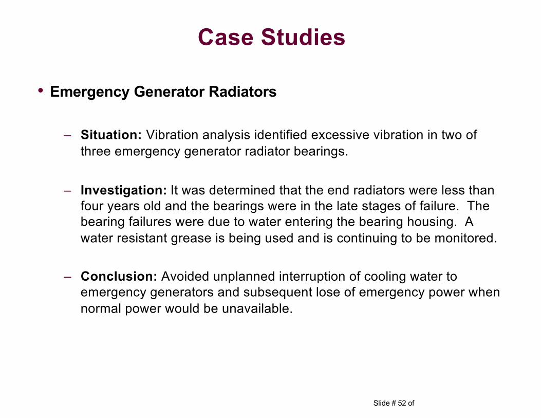
• Emergency Generator Radiators
– Situation: Vibration analysis identified excessive vibration in two of three emergency generator radiator bearings.
– Investigation: It was determined that the end radiators were less than four years old and the bearings were in the late stages of failure. The bearing failures were due to water entering the bearing housing. A water resistant grease is being used and is continuing to be monitored.
– Conclusion: Avoided unplanned interruption of cooling water to emergency generators and subsequent lose of emergency power when normal power would be unavailable.
Case Studies
Slide # 53 of
Benefits and Return on
Investment (ROI)
Reliability Centered Maintenance
Slide # 54 of
• Can be measured several ways:1. Compare annual O&M contract costs from before RCM/CBM was
implemented to after:• O&M services only (not including parts, materials or projects funds) • Requires competitively rebidding contract• Requires properly documenting reduced workload
Benefits and Return on Investment (ROI)
Slide # 55 of
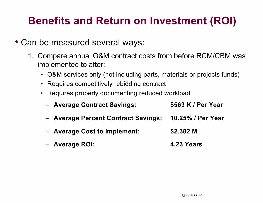
• Can be measured several ways:1. Compare annual O&M contract costs from before RCM/CBM was
implemented to after:• O&M services only (not including parts, materials or projects funds) • Requires competitively rebidding contract• Requires properly documenting reduced workload
– Average Contract Savings: $563 K / Per Year
– Average Percent Contract Savings: 10.25% / Per Year
– Average Cost to Implement: $2.382 M
– Average ROI: 4.23 Years
Benefits and Return on Investment (ROI)
Slide # 56 of
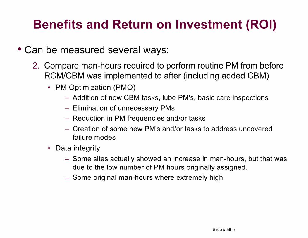
• Can be measured several ways:2. Compare man-hours required to perform routine PM from before
RCM/CBM was implemented to after (including added CBM)• PM Optimization (PMO)
– Addition of new CBM tasks, lube PM's, basic care inspections– Elimination of unnecessary PMs– Reduction in PM frequencies and/or tasks– Creation of some new PM's and/or tasks to address uncovered
failure modes• Data integrity
– Some sites actually showed an increase in man-hours, but that was due to the low number of PM hours originally assigned.
– Some original man-hours where extremely high
Benefits and Return on Investment (ROI)
Slide # 57 of
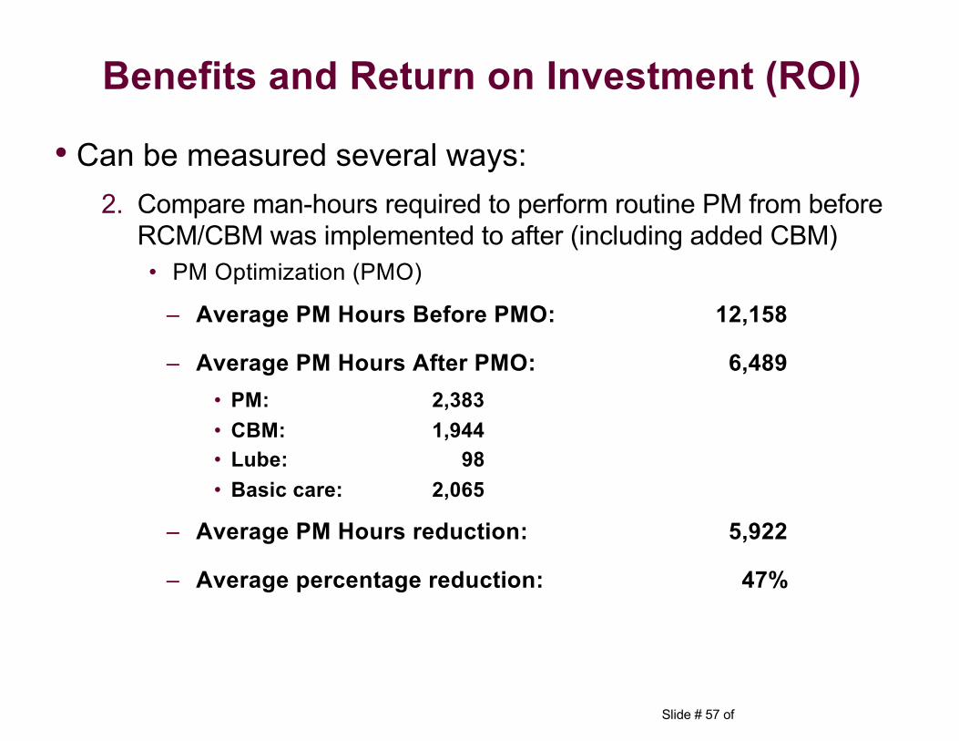
• Can be measured several ways:2. Compare man-hours required to perform routine PM from before
RCM/CBM was implemented to after (including added CBM)• PM Optimization (PMO)
– Average PM Hours Before PMO: 12,158
– Average PM Hours After PMO: 6,489• PM: 2,383• CBM: 1,944• Lube: 98• Basic care: 2,065
– Average PM Hours reduction: 5,922
– Average percentage reduction: 47%
Benefits and Return on Investment (ROI)
Slide # 58 of
• Can be measured several ways:3. Track Faults identified with CBM technology
• Initially, even equipment that appears to run adequately typically exhibits faults indicating its not running at its best performance, efficiency or reliability resulting in a lower life expectancy
• As corrections are made, a drop in faults is usually realized and equipment runs more efficiently, is more reliable resulting in a higher life expectancy
• The 1st year for CBM is usually a low number because the program did not always start on 1 Jan and remote sensors were still being installed, so not all equipment was being looked at yet
• Addition of new equipment will affect the number of faults identified as even new equipment has initial faults and defects identified by CBM technology (usually able to be repaired under warranty)
• Several of our facilities are new to the program and data is not available or we only have 1 year so trending is pointless at this time
Benefits and Return on Investment (ROI)
Slide # 59 of
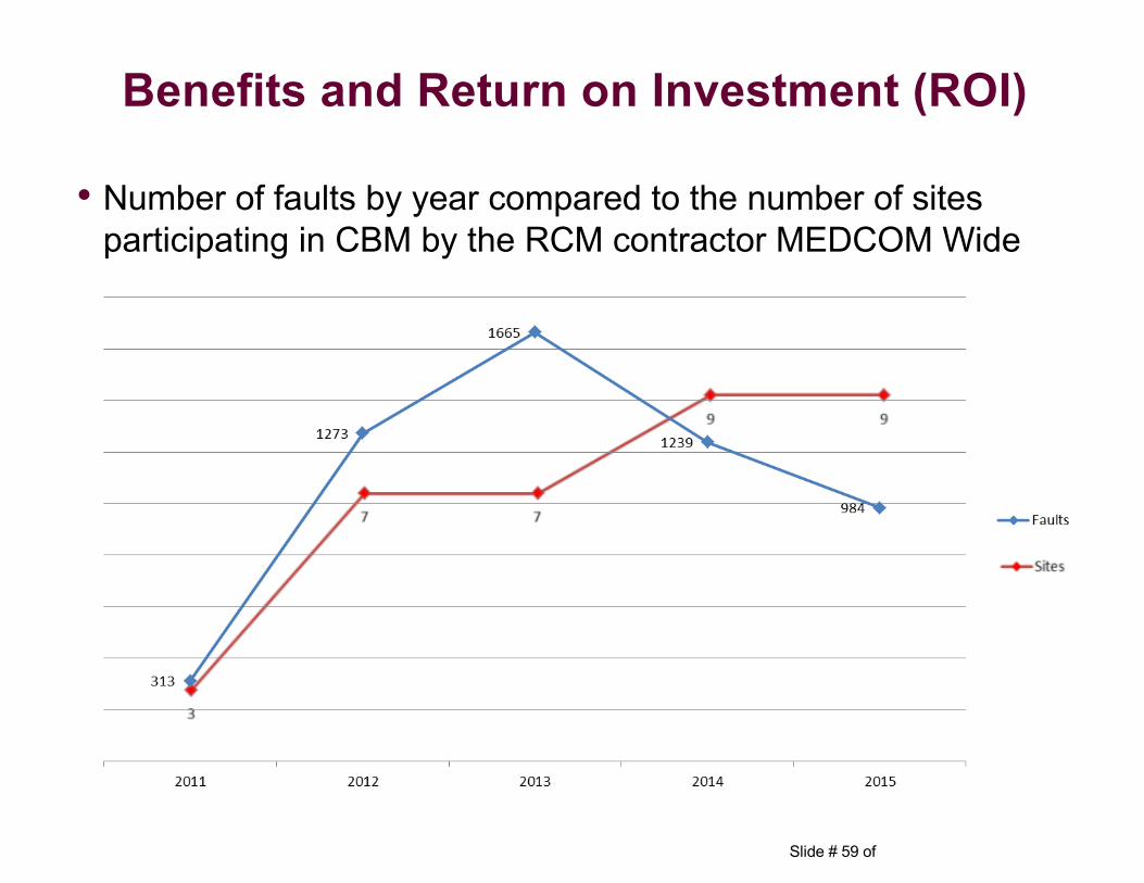
• Number of faults by year compared to the number of sites participating in CBM by the RCM contractor MEDCOM Wide
Benefits and Return on Investment (ROI)
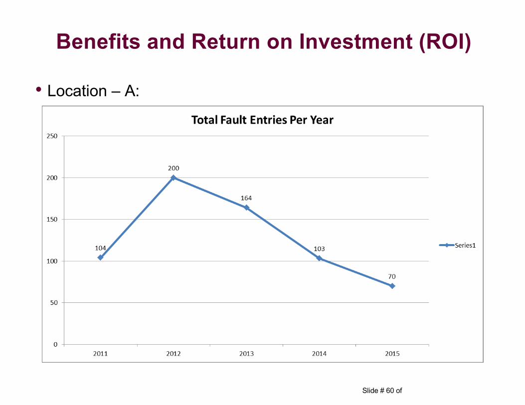
Slide # 60 of
• Location – A:
Benefits and Return on Investment (ROI)
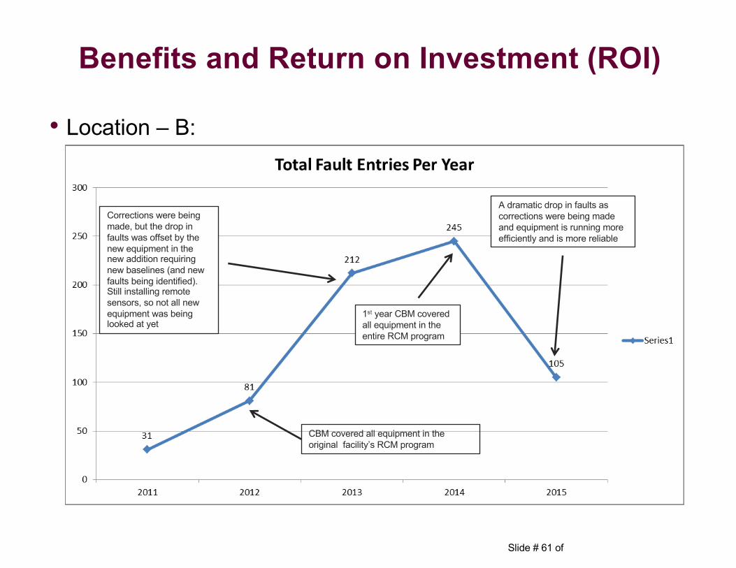
Slide # 61 of
• Location – B:
CBM covered all equipment in the original facility’s RCM program
Corrections were being made, but the drop in faults was offset by the new equipment in the new addition requiring new baselines (and new faults being identified). Still installing remote sensors, so not all new equipment was being looked at yet
1st year CBM covered all equipment in the entire RCM program
A dramatic drop in faults as corrections were being made and equipment is running more efficiently and is more reliable
Benefits and Return on Investment (ROI)
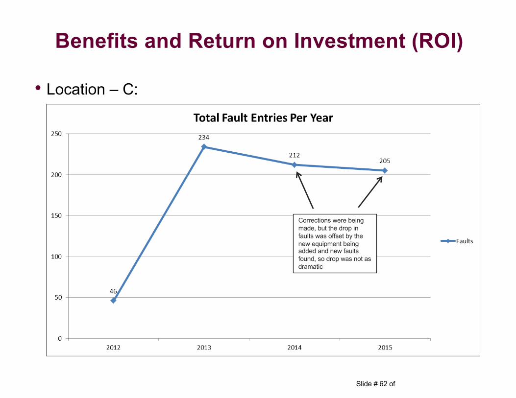
Slide # 62 of
• Location – C:
Benefits and Return on Investment (ROI)
Corrections were being made, but the drop in faults was offset by the new equipment being added and new faults found, so drop was not as dramatic
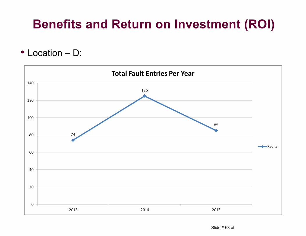
Slide # 63 of
• Location – D:
Benefits and Return on Investment (ROI)
Slide # 64 of
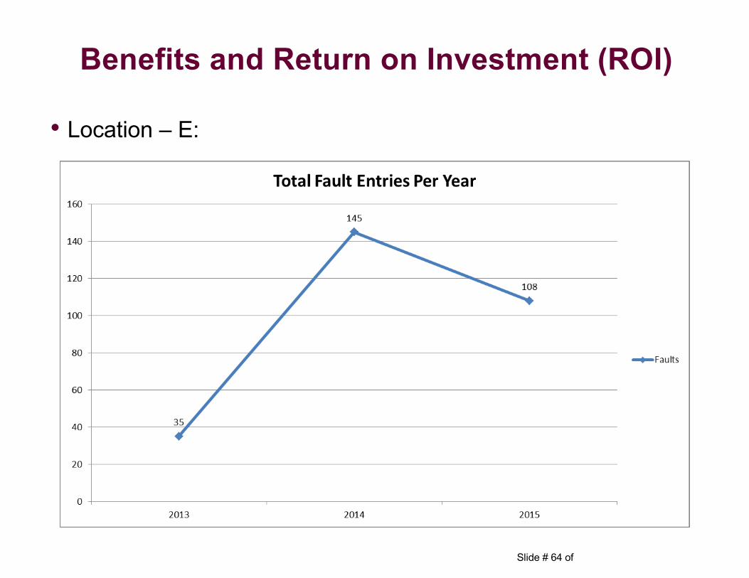
• Location – E:
Benefits and Return on Investment (ROI)
Slide # 65 of
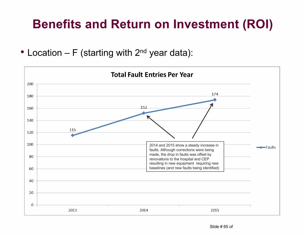
• Location – F (starting with 2nd year data):
2014 and 2015 show a steady increase in faults. Although corrections were being made, the drop in faults was offset by renovations to the hospital and CEP resulting in new equipment requiring new baselines (and new faults being identified)
Benefits and Return on Investment (ROI)
Slide # 66 of
• Take-A-Ways:– RCM has defiantly contributed to lowering O&M costs– Equipment is more reliable– Risk of critical system failures has been reduced– Equipment life is expected to be longer– Reduced man-hour requirements to perform routine maintenance
allows more time to perform other functions such as corrective maintenance and projects
Benefits and Return on Investment (ROI)
Slide # 67 of
Any Questions?
Reliability Centered Maintenance