Embed Size (px)
Citation preview

Excel 210 MRI CompatibleAnesthesia Machine
Operation and Maintenance Manual
User ResponsibilityThis Product will perform in conformity with the description thereof contained in this operatingmanual and accompanying labels and/or inserts, when assembled, operated, maintained andrepaired in accordance with the instructions provided. This Product must be checked periodically.A defective Product should not be used. Parts that are broken, missing, plainly worn, distorted orcontaminated should be replaced immediately. Should such repair or replacement becomenecessary, Datex-Ohmeda recommends that a telephonic or written request for service advice bemade to the nearest Datex-Ohmeda Field Service Support Center. This Product or any of its partsshould not be repaired other than in accordance with written instructions provided by Datex-Ohmeda and by Datex-Ohmeda trained personnel. The Product must not be altered without theprior written approval of Datex-Ohmeda’s Quality Assurance Department. The user of this Productshall have the sole responsibility for any malfunction which results from improper use, faultymaintenance, improper repair, damage, or alteration by anyone other than Datex-Ohmeda.
w CAUTIONCAUTIONCAUTIONCAUTIONCAUTION U. S. Federal and Canadian law restrict this device to sale by or on the order of alicensed medical practitioner. Outside the U. S. A. and Canada, check local laws forany restrictions that may apply.
Datex-Ohmeda products have unit serial numbers with coded logic which indicates a productgroup code, the year of manufacture and a sequential unit number for identification.
AAA A 12345
This alpha character indicates the year of product manufactureand when the serial number was assigned; “Y” = 1995, “Z” = 1996, “A” =1997, etc. “I” and “O” are not used.
1001-0809-000 11/20/99
i 1001-0809-000 11/20/99
Table of Contents
i
1/Introduction
Introduction to the Excel MRI Compatible Anesthesia System 1-1
How to use this manual 1-2
Symbols used in the manual or on the equipment 1-3
2/General Information
Identifying Excel MRI components and controls 2-1
Identifying 5125 O2 Monitor components and controls 2-6
3/Set Up
Before starting to setup the system 3-1
Mounting gas cylinders 3-1
Mounting the 5125 O2 Monitor 3-2
Circuit and monitoring connections 3-4
4/Preoperative Checkout
Before starting the checkout 4-1
MRI compatibility check 4-1
Initial Checks 4-2
Checking vaporizer mounting 4-3
Checking cylinder and pipeline supplies 4-3
Checking vaporizer back pressure 4-4
Leak checking the low pressure circuitry 4-4
Checking the gas flow controls 4-6
Breathing system checks 4-7
5125 O2 Monitor checks 4-7
5/Maintenance
Maintenance schedule 5-1
Cleaning and sterilization 5-2
Cleaning 5-2
Sterilization 5-3
Special precautions for rubber articles 5-3
O2 sensor maintenance 5-3
Installing a cartridge or disassembling the O2 sensor for cleaning 5-3
Cleaning and sterilization 5-6
Replacing the 5125 O2 Monitor battery 5-7
ii 1001-0809-000 11/20/99
Table of Contents
ii
6/Troubleshooting
Repair policy 6-1
Problems with the 5125 O2 Monitor 6-1
Calibration and drift 6-1
5125 O2 Monitor alarms 6-2
Pneumatics problems 6-3
7/Illustrated Parts
Excel specific parts 7-1
MRI Compatible accessories 7-1
5125 O2 Monitor accessories 7-2
Where to find additional part numbers 7-2
Appendix
Excel Pneumatics A-1
Excel MRI System Specifications A-4
Warranty
1-1 1001-0809-000 11/20/99
1/Introduction
1-1
w WARNINGWARNINGWARNINGWARNINGWARNING Using an MRI system in conjunction with general anesthesia on cardiac patients,febrile patients, and patients with impaired ability to perspire may present a patienthealth hazard.
In this sectionIn this sectionIn this sectionIn this sectionIn this section
Introduction to the Excel MRI Compatible Anesthesia System 1-1
How to use this manual 1-2
Symbols used in the manual or on the equipment 1-3
Introduction to the Excel MRI Compatible Anesthesia SystemIntroduction to the Excel MRI Compatible Anesthesia SystemIntroduction to the Excel MRI Compatible Anesthesia SystemIntroduction to the Excel MRI Compatible Anesthesia SystemIntroduction to the Excel MRI Compatible Anesthesia System
The Datex-Ohmeda commitment to meeting your anesthesia needs continues with the ExcelMagnetic Resonance Imaging (MRI) Compatible Excel Anesthesia System.
Basic features
The Excel MRI System includes:
• Three gases, oxygen, nitrous oxide, and air. All gases have pipeline and cylinder connections.
• The 5125 MRI Compatible O2 Monitor with adjustable high and low O2 alarms, and built inbattery and hardware self tests.
• A two vaporizer manifold.
MRI Compatibility
The Excel MRI is constructed primarily of non-ferous materials to help prevent attraction to thecryogenic magnets in MRI systems.
The Excel MRI and attached accessories performed to specifications when tested together as asystem directly next to an unshielded, 1.5 Tesla MRI unit with a magnetic fringe field below 0.23Tesla (2300 Gauss).
Approved accessories
A wide variety of Datex-Ohmeda accessories have been approved for use in conjunction with theExcel MRI under test conditions:
w WARNINGWARNINGWARNINGWARNINGWARNING The MRI compatibility of these accessories applies to specific accessory models andis limited to use as part of the Excel MRI System. None of these accessories havebeen tested for stand alone use in an MRI environment or in magnetic fringe fieldsabove 0.23 Tesla (2300 Gauss).
• Tec 4 or 5 vaporizers; keyed or funnel fill models.
• GMS Absorber, PEEP valve, and Bain Circuit adapter
• Waste Gas Scavenging Valve
• 121 Respirometer
• Standard or free flow suction regulator kits
• Auxiliary oxygen flowmeter
• Flip-up shelf
1-2 1001-0809-000 11/20/99
1/Introduction
1-2
• Storage cabinets
• Dovetail mounted accessories: a 1 x 3.5 inch post with two inch extension; a 12 inch IV Pole; alarge case Tycos gauge; and holders and regulators for E-size O2 and N2O cylinders.
Because approval applies only to specific accessory models, consult the Illustrated Parts Sectionof this manual for Stock Numbers.
Safety features
The Excel MRI includes several important safety features:
• The Datex-Ohmeda Link 25 Proportion Limiting Control System limits the lowest oxygenconcentration that can be delivered on the Excel MRI to a nominal 25% for O2/N2O mixtures atthe common gas outlet.
• An audible low O2 supply alarm alerts you if the O2 pressure falls below a nominal 207 kPa(30 psig).
• N2O and air flows stop if O2 supply pressure falls below a nominal 138 kPa (20 psig).
• An interlock mechanism that helps prevent more than one Datex-Ohmeda Tec 4 or Tec 5vaporizer from being “On” at once. An isolation system also helps prevent fresh gas fromentering a vaporizer that is not switched “On.”
• Low battery alarms and built in self tests on the 5125 O2 Monitor.
• Differentiated pipeline and cylinder gauges.
• Gas specific pipeline and cylinder connections.
• A guarded O2 flush button.
• Color coded flow controls and pressure gauges.
Operator convenience
For your convenience, the Excel MRI also features:
• An O2 power outlet
• Full length dovetail accessory mounting.
• A single action brake/footrest.
• Shelf space for additional monitoring.
• Large, easy-running casters and a compact frame.
How to use this manualHow to use this manualHow to use this manualHow to use this manualHow to use this manual
This manual covers the Excel MRI System and the MRI Compatible 5125 O2 Monitor. Vaporizers,the GMS Absorber, the Waste Gas Scavenging Valve and other major accessories also haveindividual operation and maintenance manuals. A complete set of operation and maintenancemanuals comes with the Excel MRI System. Datex-Ohmeda recommends that you keep thismanual and all related manuals available for reference.
If you are using the system for the first time, read this manual first. Then read the operation andmaintenance manuals for the system components. Before you go on to Chapter 2, “GeneralInformation,” make sure that you understand the symbols listed at the end of this chapter.
If you have used the Excel MRI before, complete the step-by-step set up procedure in Chapter 3.Then turn to Chapter 4 “Preoperative Checkout,” which is required before using the Excel MRI.
1-3 1001-0809-000 11/20/99
1/Introduction
1-3
Before cleaning the Excel MRI, read Chapter 5, “Maintenance,” carefully. This section also tellsyou how to change the O2 Monitor battery and assemble and service the O2 sensor (sensorcartridge replacement, disassembly for cleaning).
Chapter 6, “Troubleshooting,” helps you solve problems that may occur with the Excel MRI or the5125 O2 Monitor. For example, how can you tell if a low pressure leak is due to a vaporizer thatyou can replace or an internal fault that requires a service call? (If the leak follows a particularvaporizer and the external o-ring is in place, replace the vaporizer.)
Chapter 7, “Illustrated Parts,” tells you how to order replacement parts and accessories. It alsolists part numbers for all operation and maintenance manuals associated with the Excel MRISystem.
The Appendix lists Excel MRI and 5125 O2 Monitor specifications and describes the internalpneumatic circuitry of the Excel MRI.
Please also take a moment to review the User Responsibility Statement on the inside of the frontcover; it describes what is expected of you to maintain the Excel MRI. Also read the Warranty onthe back cover; it outlines Datex-Ohmeda’s responsibility in case of a functional defect.
Symbols used in the manual or on the equipmentSymbols used in the manual or on the equipmentSymbols used in the manual or on the equipmentSymbols used in the manual or on the equipmentSymbols used in the manual or on the equipment
w WarningsWarningsWarningsWarningsWarnings and w Cautions Cautions Cautions Cautions Cautions tell you about dangerous conditions that can occur if you do notobey all of the instructions in this manual.
Warnings tell you about a condition that can cause injury to the operator or the patient. Cautionstell you about a condition that can cause damage to the equipment. Read and obey all warningsand cautions.
Other symbols replace words on the equipment or in Datex-Ohmeda manuals. No one device ormanual uses all of the symbols. These symbols include:
ø On (power)
O Off (power)
o Standby
q Standby or preparatory state for a part of the equipment
p “ON” only for part of the equipment
œ “OFF” only for part of the equipment
† Direct Current
∏ Alternating Current
x Protective earth ground
1-4 1001-0809-000 11/20/99
1/Introduction
1-4
y Earth Ground
r Frame or chassis ground
å Alarm silence button
Y Equipotential
t Variability
T Variability in steps
+ Plus, positive polarity
Ë Minus, negative polarity
P Lamp, lighting, illumination
N Movement in one direction
ˆ Movement in both directions
z Lock
Z Unlock
134°C Autoclavable
Í Non-autoclavable
m Type B equipment
µ Type BF equipment
H Type CF equipment
w Caution, ISO 7000-0434
wW Attention, consult accompanying documents, IEC 601-1
Ê This way up
π Dangerous Voltage
1-5 1001-0809-000 11/20/99
1/Introduction
1-5
≈ Input
Ù Output
REF Stock Number
SN Serial Number
Systems with this mark agree with European Council Directive (93/42/EEC) forMedical Devices when they are used as specified in their Operation andMaintenance Manuals. The xxxx is the certification number of the Notified Bodyused by Datex-Ohmeda’s Quality Systems.
Read top of float
Vacuum inlet
Suction bottle outlet
O2+ O2 Flush button
Cylinder
Isolation transformer
Linkage system
Risk of Explosion
Low pressure leak test
R Bag position/ manual ventilation
u Open drain (remove liquid)
U Close drain
q Inspiratory flow
Q Expiratory flow
t O2 sensor connection
r Mechanical ventilation
1-6 1001-0809-000 11/20/99
1/Introduction
1-6
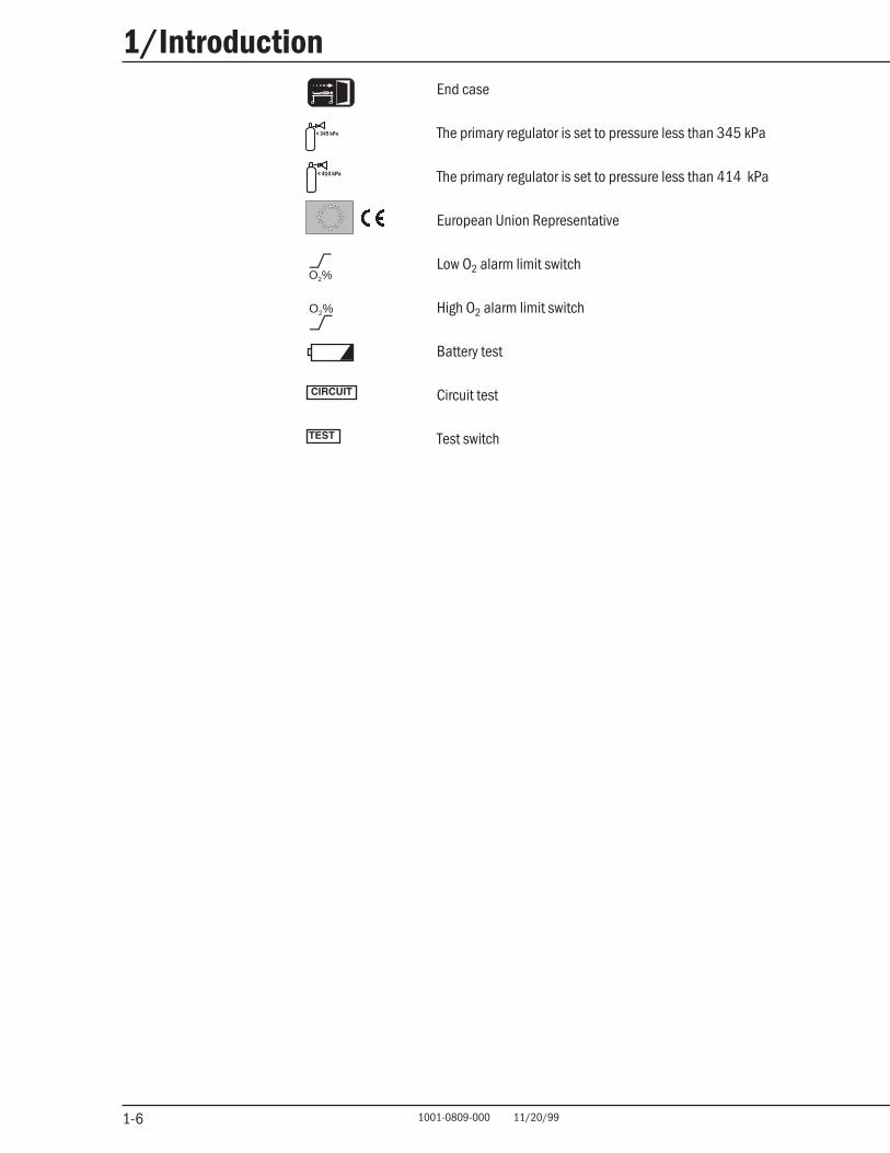
End case
The primary regulator is set to pressure less than 345 kPa
The primary regulator is set to pressure less than 414 kPa
European Union Representative
Low O2 alarm limit switch
High O2 alarm limit switch
Battery test
Circuit test
Test switch
< 345 kPa
< 414 kPa
O2%
O2%
2-1 1001-0809-000 11/20/99
2/General Information
2-1
In this sectionIn this sectionIn this sectionIn this sectionIn this section
Identifying Excel MRI components and controls 2-1
Identifying 5125 O2 Monitor components and controls 2-6
wWARNINGWARNINGWARNINGWARNINGWARNING The Datex-Ohmeda Excel System must only be used with non-flammable anestheticagents.
Identifying Excel MRI components and controlsIdentifying Excel MRI components and controlsIdentifying Excel MRI components and controlsIdentifying Excel MRI components and controlsIdentifying Excel MRI components and controls
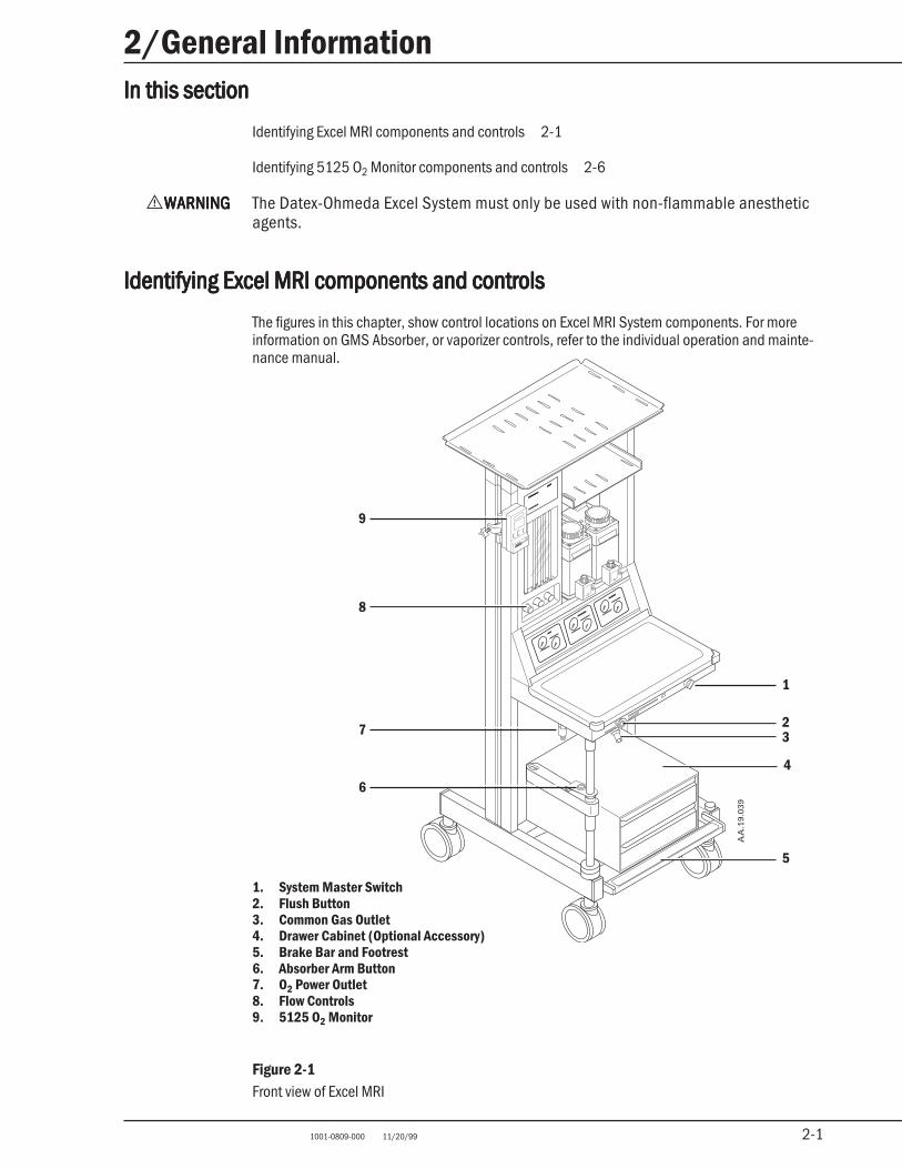
The figures in this chapter, show control locations on Excel MRI System components. For moreinformation on GMS Absorber, or vaporizer controls, refer to the individual operation and mainte-nance manual.
1
32
5
AA
.19.
039
6
7
9
4
8
1. System Master Switch2. Flush Button3. Common Gas Outlet4. Drawer Cabinet (Optional Accessory)5. Brake Bar and Footrest6. Absorber Arm Button7. O2 Power Outlet8. Flow Controls9. 5125 O2 Monitor
Figure 2-1Front view of Excel MRI
2-2 1001-0809-000 11/20/99
2/General Information
2-2
Flow controls
With the system master switch set to “On,” turning a flow control counterclockwise increases flow,turning a flow control clockwise decreases flow. A linkage between the N2O and the O2 flowcontrols limits the lowest oxygen concentration that can be set on the Excel MRI to a nominal 25%for O2/N2O mixtures at the common gas outlet. Flow ranges are: O2, 200 ml/min to 10 l/min (plusup to two additional turns of the knob); N2O, 0 to 10 l/min (plus up to one additional turn of theknob ); air, 0 to 15 l/min (plus up to one additional turn of the knob).
System master switch
Setting the system master switch to “On” allows gas to flow through the Excel MRI.
Flush button
Pressing the O2 Flush button delivers 45-70 l/min of O2 through the common gas outlet.
Common gas outlet
The common gas outlet delivers anesthetic gases to the patient circuit.
Brake
Push down to keep the Excel MRI from rolling. Lift up to release.
Absorber arm button
Press this button to adjust the height of the absorber arm.
O2 power outlet
Provides drive gas for MRI compatible pneumatic equipment.
2-3 1001-0809-000 11/20/99
2/General Information
2-3
AA.1
9.04
0
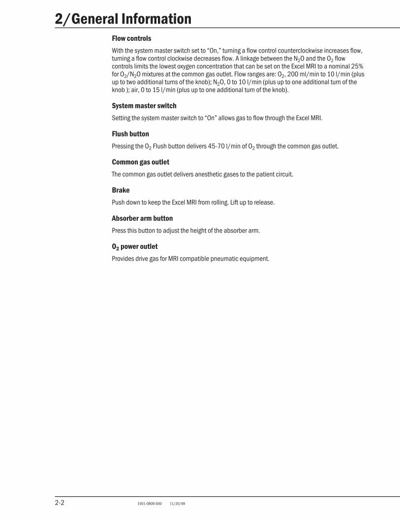
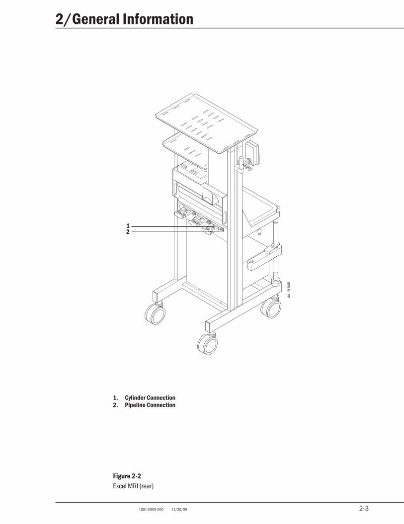
1. Cylinder Connection2. Pipeline Connection
Figure 2-2Excel MRI (rear)
12
2-4 1001-0809-000 11/20/99
2/General Information
2-4
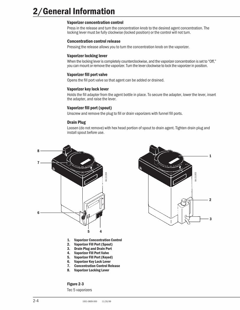
Vaporizer concentration controlPress in the release and turn the concentration knob to the desired agent concentration. Thelocking lever must be fully clockwise (locked position) or the control will not turn.
Concentration control releasePressing the release allows you to turn the concentration knob on the vaporizer.
Vaporizer locking leverWhen the locking lever is completely counterclockwise, and the vaporizer concentration is set to “Off,”you can mount or remove the vaporizer. Turn the lever clockwise to lock the vaporizer in position.
Vaporizer fill port valveOpens the fill port valve so that agent can be added or drained.
Vaporizer key lock leverHolds the fill adapter from the agent bottle in place. To secure the adapter, lower the lever, insertthe adapter, and raise the lever.
Vaporizer fill port (spout)Unscrew and remove the plug to fill or drain vaporizers with funnel fill ports.
Drain PlugLoosen (do not remove) with hex head portion of spout to drain agent. Tighten drain plug andinstall spout before use.
7
6
2
18
45
AA.1
3.00
3
AA.1
3.00
4
1. Vaporizer Concentration Control2. Vaporizer Fill Port (Spout)3. Drain Plug and Drain Port4. Vaporizer Fill Port Valve5. Vaporizer Fill Port (Keyed)6. Vaporizer Key Lock Lever7. Concentration Control Release8. Vaporizer Locking Lever
Figure 2-3Tec 5 vaporizers
3
2-5 1001-0809-000 11/20/99
2/General Information
2-5
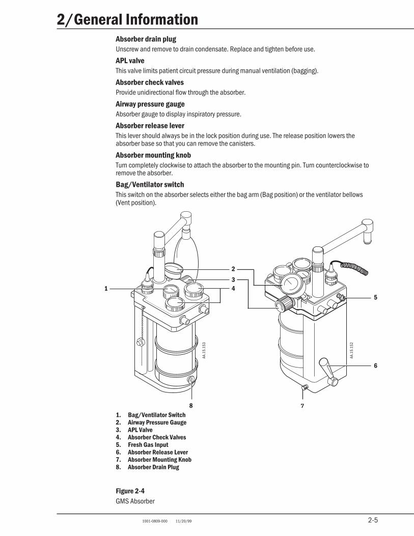
Absorber drain plugUnscrew and remove to drain condensate. Replace and tighten before use.
APL valveThis valve limits patient circuit pressure during manual ventilation (bagging).
Absorber check valvesProvide unidirectional flow through the absorber.
Airway pressure gaugeAbsorber gauge to display inspiratory pressure.
Absorber release leverThis lever should always be in the lock position during use. The release position lowers theabsorber base so that you can remove the canisters.
Absorber mounting knobTurn completely clockwise to attach the absorber to the mounting pin. Turn counterclockwise toremove the absorber.
Bag/Ventilator switchThis switch on the absorber selects either the bag arm (Bag position) or the ventilator bellows(Vent position).
2
341
5
6
AA.1
5.15
2
AA.1
5.15
3
8 7
1. Bag/Ventilator Switch2. Airway Pressure Gauge3. APL Valve4. Absorber Check Valves5. Fresh Gas Input6. Absorber Release Lever7. Absorber Mounting Knob8. Absorber Drain Plug
Figure 2-4GMS Absorber
2-6 1001-0809-000 11/20/99
2/General Information
2-6
5125
Identifying 5125 OIdentifying 5125 OIdentifying 5125 OIdentifying 5125 OIdentifying 5125 O22222 Monitor components and controls Monitor components and controls Monitor components and controls Monitor components and controls Monitor components and controls
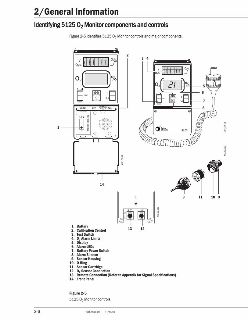
Figure 2-5 identifies 5125 O2 Monitor controls and major components.
1. Battery2. Calibration Control3. Test Switch4. O2 Alarm Limits5. Display6. Alarm LEDs7. Battery Power Switch8. Alarm Silence9. Sensor Housing
10. O-Ring11. Sensor Cartridge12. O2 Sensor Connection13. Remote Connection (Refer to Appendix for Signal Specifications)14. Front Panel
Figure 2-55125 O2 Monitor controls
o2%
10 mVper
MinR
L20M
MD.
12.0
19
MD.
12.0
13
MD.
12.0
14
MD.
02.0
32
1
23 4
5
6
7
8
910119
1213
14
2-7 1001-0809-000 11/20/99
2/General Information
2-7
Test switch
Pressing down the top half of the switch (Batt Test) checks the battery condition. Holding down thebottom half of the switch (Circuit Test) checks the 5125 O2 Monitor’s electronic circuitry. Forinformation about using the switch, refer to the section “5125 O2 Monitor checks” at the end ofChapter 4.
Low O2 alarm
Sets the lowest acceptable O2 concentration. O2 concentrations below 18% trigger a low O2 alarmregardless of the alarm limit. Setting the limit below 18% also triggers an alarm.
High O2 alarm
Sets the highest allowed O2 concentration (0 to 99%). Setting the limit to 00% disables the alarm.
Display
Shows the measured O2 concentration and any alarm messages.
Battery Power switch
Switches the 5125 O2 Monitor “On” and “Off.”
Alarm Silence
Pressing the alarm silence button silences all audible alarms, except for low O2, until the nextoccurrence. Low O2 alarms are silenced for 30 seconds. While the alarm is silenced, any flashingLEDs stay on continuously.
O2 sensor housing and cartridge
The 5125 O2 Monitor uses the standard Datex-Ohmeda O2 sensor. The sensor cartridge is not partof the O2 sensor assembly and must be installed before use. For additional information refer to thesection “O2 sensor maintenance” in Chapter 5.
Battery
The 5125 O2 Monitor uses a “C” size, non-magnetic, 3.9 Vdc lithium battery. During operation, the“BATT FAIL” alarm continuously monitors battery strength.
Calibration control
Use the calibration control (CAL) to calibrate the 5125 O2 Monitor for 21% and 100% O2. Refer to“5125 O2 Monitor checks” at the end of Chapter 4.

2-8 1001-0809-000 11/20/99
2/General Information
2-8
Notes
3-1 1001-0809-000 11/20/99
3/Setup
3-1
In this sectionIn this sectionIn this sectionIn this sectionIn this section
Before starting to setup the system 3-1
Mounting gas cylinders 3-1
Mounting the 5125 O2 monitor 3-2
Circuit and monitoring connections 3-4
Before starting to setup the systemBefore starting to setup the systemBefore starting to setup the systemBefore starting to setup the systemBefore starting to setup the system
w WARNINGWARNINGWARNINGWARNINGWARNING Remove the Excel MRI from the MRI room before starting the setup procedure. Do notadd or remove any anesthesia system components while the Excel MRI System is inthe MRI room.
1. Remove the Excel MRI System from the MRI room before starting the setup procedures.
2. Complete the setup procedure outside the MRI environment.
3. Do not move the Excel MRI System into the MRI room until you complete the first threesections of the checkout procedure (“MRI compatibility check,” “Initial checks,” and “Check-ing vaporizer mounting”).
Mounting gas cylindersMounting gas cylindersMounting gas cylindersMounting gas cylindersMounting gas cylinders
w WARNINGWARNINGWARNINGWARNINGWARNING Use only non-magnetic gas cylinders on the Excel MRI System.
1. Set the system master switch to “Off.”
2. Swing out the yoke clamp.
3. Unscrew the tee handle until the screw is flush with the inside of the clamp.
4. Make sure that the cylinder valve is not covered by a dust cap. Remove dust cap if present.
5. Remove the old cylinder gasket if present and install a new gasket.
Note: Make sure that the old gasket does not stick to the cylinder.
w CAUTIONCAUTIONCAUTIONCAUTIONCAUTION Use one cylinder gasket per yoke. Extra gaskets may cause a leak. Not using acylinder gasket will also cause a leak.
3-2 1001-0809-000 11/20/99
3/Setup
3-2
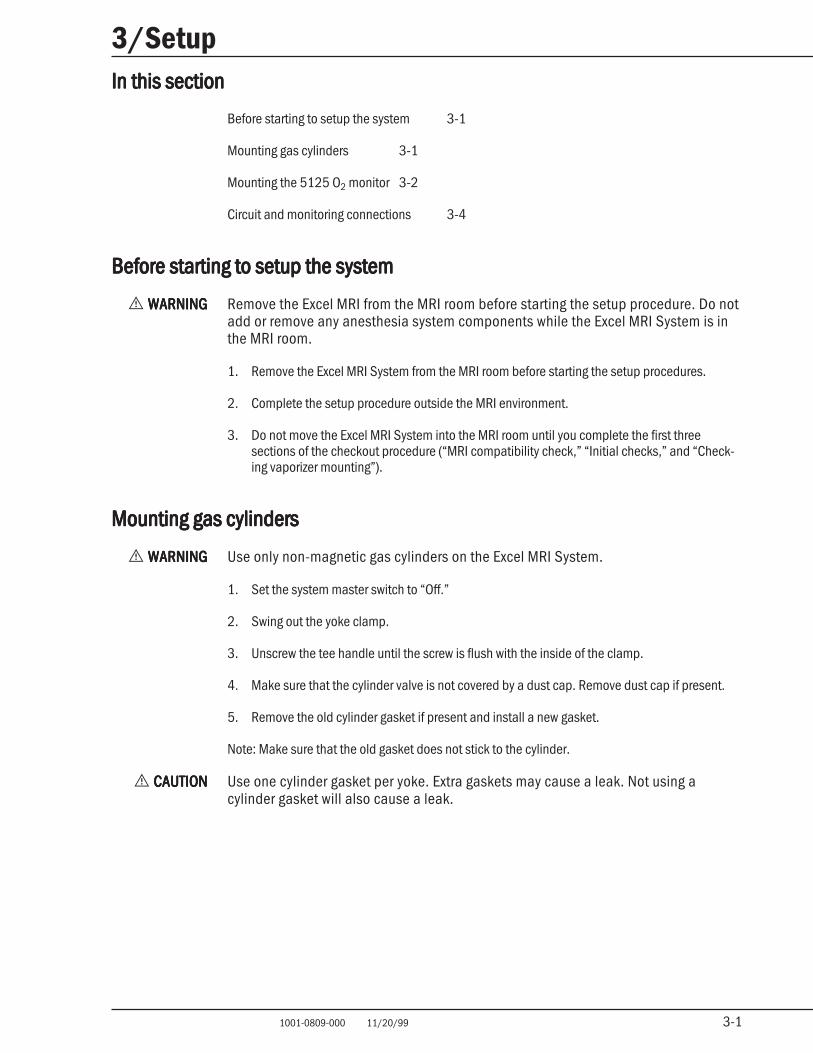
1. Gasket2. Tee Handle3. Yoke Clamp4. Pipeline Inlet
Figure 3-1Mounting gas cylinders
6. Line the yoke index pins up with the cylinder post and swing the clamp closed.
7. Hand tighten the tee handle to secure the cylinder.
8. Install cylinder plugs and gaskets in all unused yoke positions.
9. Verify that the cylinder wrench is present.
w WARNINGWARNINGWARNINGWARNINGWARNING Always close the cylinder valve when you are using a pipeline supply. If a cylindervalve is open and the pipeline and regulated cylinder pressures are equal, bothsupplies may be used simultaneously, leaving an insufficient reserve in case ofpipeline failure.
Mounting the 5125 OMounting the 5125 OMounting the 5125 OMounting the 5125 OMounting the 5125 O22222 monitor monitor monitor monitor monitor
1. Tighten the thumb screw on the mounting post. This pushes a spring loaded plate in, reducingthe width of the block.
2. Fit the mounting block into the mounting track on the left hand side of the Excel MRI. Loosenthe thumb screw. This wedges the plate against the sides of the mounting track.
1 2 3 4
AA
.11.
194
3-3 1001-0809-000 11/20/99
3/Setup
3-3
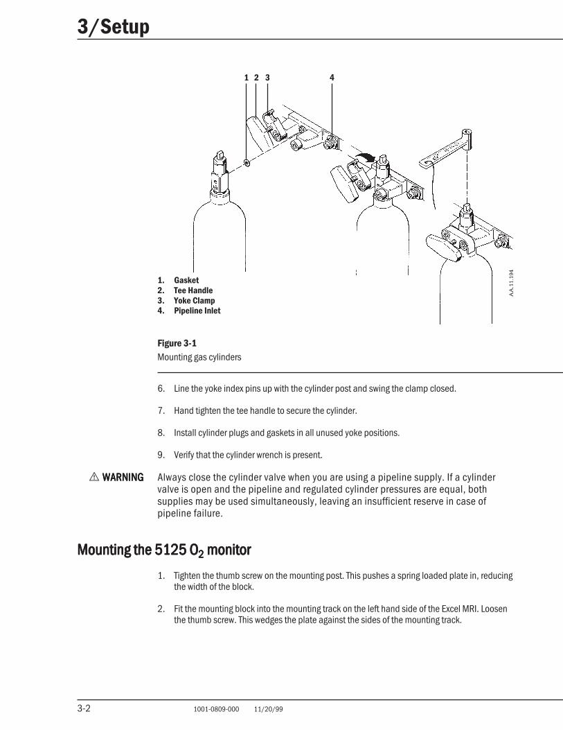
1. O2 Monitor2. O2 Sensor Connection3. Nut4. Clamp5. Thumb Screw6. Plate7. Utility Post8. Mounting Track
Figure 3-2Mounting the 5125 O2 Monitor
3. Make sure that the utility post is secure and that both sides of the block are wedged into therail.
4. Screw the clamp into the threaded hole in the back of the 5125 O2 Monitor.
5. Attach the clamp to the utility post.
6. To adjust the angle of the 5125 O2 Monitor, loosen the nut behind the monitor, reposition themonitor and tighten the nut.
7. Connect the O2 sensor to the 5125 O2 Monitor. Refer to the section “O2 sensor maintenance”in Chapter 5 for O2 sensor assembly instructions.
MD
.12.
008
7
8
5
34
2
1
6
3-4 1001-0809-000 11/20/99
3/Setup
3-4
Circuit and monitoring connectionsCircuit and monitoring connectionsCircuit and monitoring connectionsCircuit and monitoring connectionsCircuit and monitoring connections
Use this section as a quick reference if you are already familiar with system connections. Fordetailed information and accessory part numbers, refer to the individual operation and mainte-nance manual.
w WARNINGWARNINGWARNINGWARNINGWARNING Use only Datex-Ohmeda specified cables, hoses, and tubing for external connec-tions. Alternative cables, hoses, or tubing could cause false sensor readings ordamage to the system.
1. Set the system master switch to “Off.”
2. Make sure that the absorber and the 5125 O2 Monitor are securely mounted.
3. Make the monitoring connections:
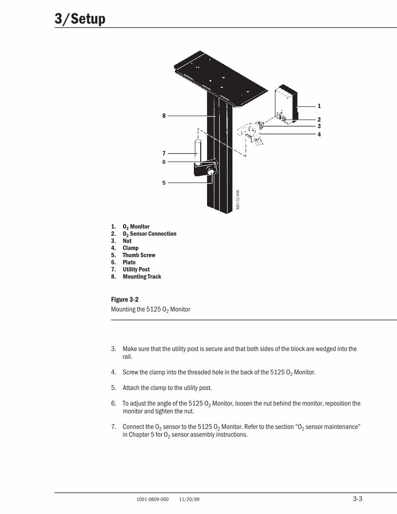
w WARNINGWARNINGWARNINGWARNINGWARNING Figure 3-3 and 3-4 show the only approved use of the 121 Respirometer with theExcel MRI.
• Refer to Figure 3-3 if you have a GMS absorber
• Refer to Figure 3-4 if you do not have a GMS absorber
Output Sensor
AA
.19.
036
1
2
5
4
3
1. O2 Sensor2. GMS Absorber3. Absorber Expiratory Port4. 121 Respirometer5. 5125 O2 Monitor
Figure 3-3O2 sensor connection to a GMS Absorber
3-5 1001-0809-000 11/20/99
3/Setup
3-5
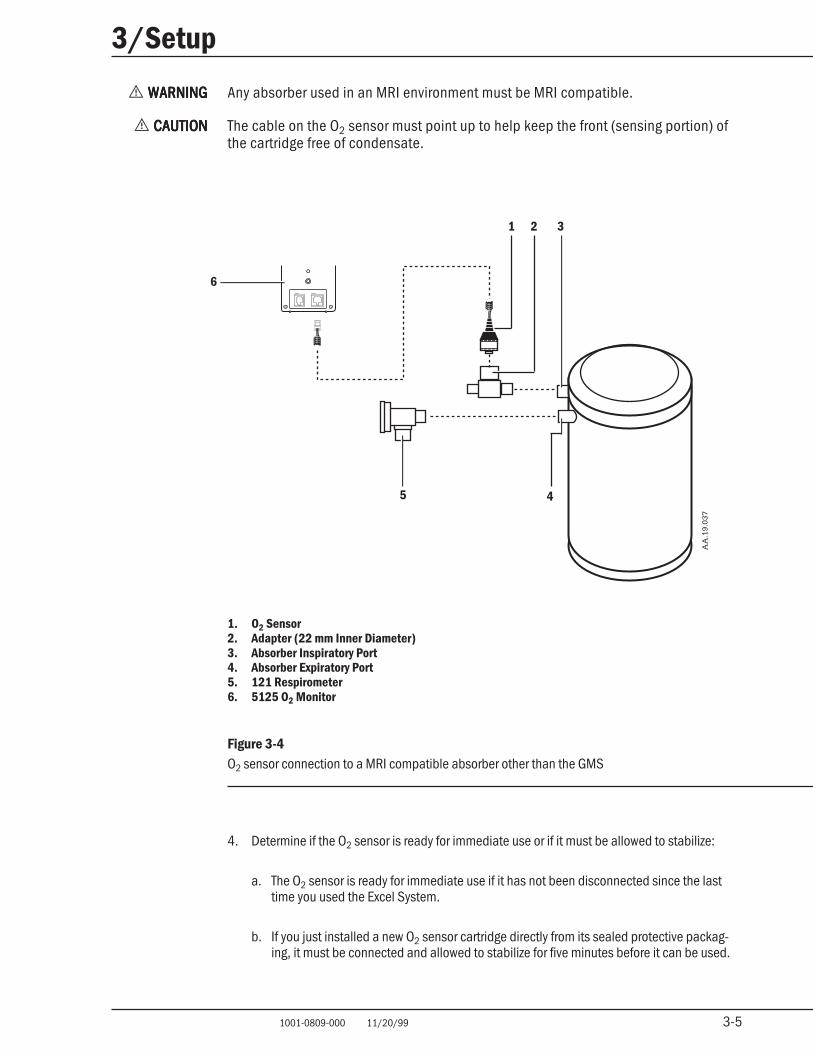
w WARNINGWARNINGWARNINGWARNINGWARNING Any absorber used in an MRI environment must be MRI compatible.
w CAUTIONCAUTIONCAUTIONCAUTIONCAUTION The cable on the O2 sensor must point up to help keep the front (sensing portion) ofthe cartridge free of condensate.
1. O2 Sensor2. Adapter (22 mm Inner Diameter)3. Absorber Inspiratory Port4. Absorber Expiratory Port5. 121 Respirometer6. 5125 O2 Monitor
Figure 3-4O2 sensor connection to a MRI compatible absorber other than the GMS
4. Determine if the O2 sensor is ready for immediate use or if it must be allowed to stabilize:
a. The O2 sensor is ready for immediate use if it has not been disconnected since the lasttime you used the Excel System.
b. If you just installed a new O2 sensor cartridge directly from its sealed protective packag-ing, it must be connected and allowed to stabilize for five minutes before it can be used.
Output Sensor
1 2 3
6
5 4
AA
.19.
037
3-6 1001-0809-000 11/20/99
3/Setup
3-6
c. If the O2 sensor was disconnected or a new O2 sensor was previously removed from itsprotective packaging, it must be connected and allowed to stabilize. Allow the O2 sensorto stabilize for as many hours as it was disconnected or removed from its package (up to amaximum of 24 hours).
w WARNINGWARNINGWARNINGWARNINGWARNING Any ventilator used with the Excel must have a high pressure alarm and relief systemfor the patient circuit.
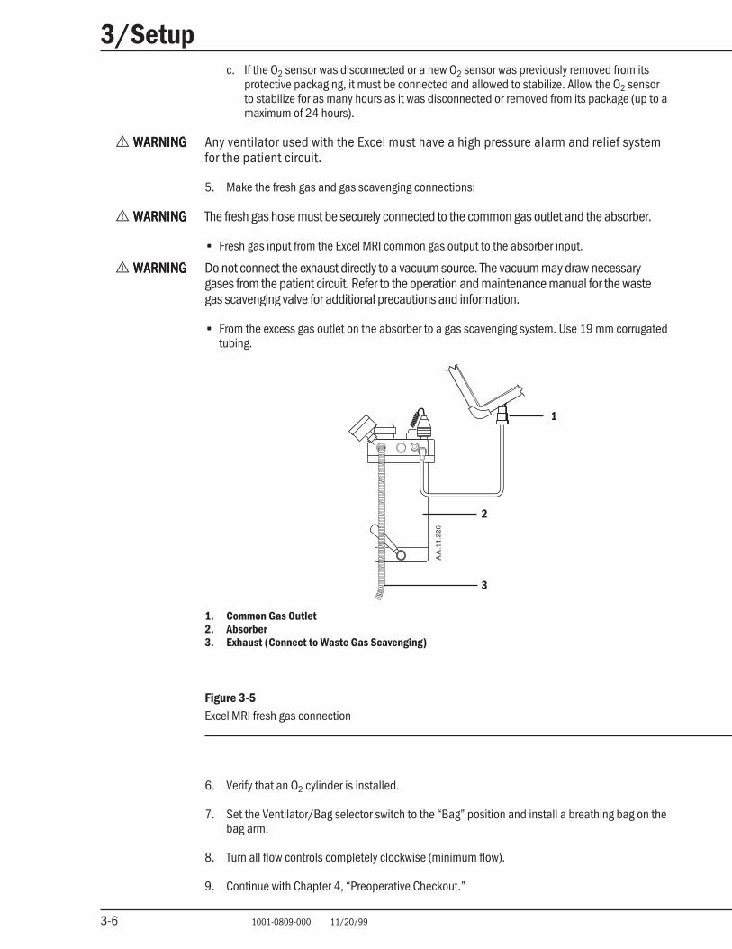
5. Make the fresh gas and gas scavenging connections:
w WARNINGWARNINGWARNINGWARNINGWARNING The fresh gas hose must be securely connected to the common gas outlet and the absorber.
• Fresh gas input from the Excel MRI common gas output to the absorber input.
w WARNINGWARNINGWARNINGWARNINGWARNING Do not connect the exhaust directly to a vacuum source. The vacuum may draw necessarygases from the patient circuit. Refer to the operation and maintenance manual for the wastegas scavenging valve for additional precautions and information.
• From the excess gas outlet on the absorber to a gas scavenging system. Use 19 mm corrugatedtubing.
1
2
3
AA
.11.
226
1. Common Gas Outlet2. Absorber3. Exhaust (Connect to Waste Gas Scavenging)
Figure 3-5Excel MRI fresh gas connection
6. Verify that an O2 cylinder is installed.
7. Set the Ventilator/Bag selector switch to the “Bag” position and install a breathing bag on thebag arm.
8. Turn all flow controls completely clockwise (minimum flow).
9. Continue with Chapter 4, “Preoperative Checkout.”
4-1 1001-0809-000 11/20/99
4/Preoperative Checkout
4-1
In this sectionIn this sectionIn this sectionIn this sectionIn this section
Before starting the checkout 4-1
MRI compatibility check 4-1
Initial Checks 4-2
Checking vaporizer mounting 4-3
Checking cylinder and pipeline supplies 4-3
Checking vaporizer back pressure 4-4
Leak checking the low pressure circuitry 4-4
Checking the gas flow controls 4-6
Breathing system checks 4-7
5125 O2 Monitor checks 4-7
Before starting the checkoutBefore starting the checkoutBefore starting the checkoutBefore starting the checkoutBefore starting the checkoutThis section—“Preoperative Checkout” —describes the minimum checks that should be madebefore the Datex-Ohmeda Excel MRI System is used on a patient. Do not use the system if it doesnot function correctly, as described in the preoperative checkout procedures; instead call aqualified service representative.
w WARNINGSWARNINGSWARNINGSWARNINGSWARNINGS Always complete the preoperative checkout procedures in this section before usingthe Excel MRI System on a patient.
w Make sure that you understand the correct connection, use and necessary precau-tions for all system components before using the Excel MRI System. For additionalprecautions and information, refer to the operation and maintenance manuals foreach component.
MRI compatibility checkMRI compatibility checkMRI compatibility checkMRI compatibility checkMRI compatibility check
w WARNINGSWARNINGSWARNINGSWARNINGSWARNINGS Do not move the Excel MRI into the MRI room until you have completed the first threesections of this chapter “MRI compatibility check,” “Initial checks” and “Checkingvaporizer mounting.” Complete the rest of the checkout using the actual room,pipeline and electrical supplies and gas cylinders that will be used during the case.
w Datex-Ohmeda strongly recommends using only monitor sensors that are compatiblewith MRI applications. Use of monitoring device sensors (ECG monitor leads, oxime-ter probes, etc.) in an MRI environment can cause injury. Check sensor locations onthe patient’s body for signs of discomfort, heating or warming.
1. Check that the gas cylinders are non-magnetic.
2. Open any drawers and check that they contain only MRI compatible items. Test any suspectitems. Remove any items that are not MRI compatible.
3. If a ventilator is connected that is not MRI compatible (e.g. a Datex-Ohmeda 7000 or a 7800Ventilator), remove it from the Excel MRI. Any ventilator used must be MRI compatible.
w WARNINGWARNINGWARNINGWARNINGWARNING Use only MRI compatible accessories with the Excel MRI. This includes monitors.
4. Remove any other accessories that are not MRI compatible.
4-2 1001-0809-000 11/20/99
4/Preoperative Checkout
4-2
Initial checksInitial checksInitial checksInitial checksInitial checks
w CAUTIONCAUTIONCAUTIONCAUTIONCAUTION Do not exceed the following shelf weight limits: top shelf, 23 kg (50 lbs); middleshelf, 11 kg (24 lbs). Verify that all equipment on the top shelf is securely strapped inplace.
1. Check the overall integrity of the machine. Make sure that:
• The casters are securely attached
• All accessories are properly mounted
• Setting the brake helps prevent the front casters from turning
2. Make sure the breathing circuit is complete, undamaged, and, if appropriate, containsadequate CO2 absorbent.
w WARNINGWARNINGWARNINGWARNINGWARNING Ensure that all hoses, tubing, and other circuit connections are made properly beforeusing this anesthesia system. Failure to do so may result in patient injury. Refer to theoperation and maintenance manuals for these devices.
3. Make sure that the following are not damaged:
• Cylinder yokes
• Pipeline inlets
• Flowmeters and flow control valves
• Pressure gauges
• Vaporizers
• Monitors and cables
• All hoses and tubing
4. Make sure the breathing circuit is closed and connected to a gas scavenging system.
5. Check that the cylinders are properly installed.
6. Check that the vaporizers are properly installed.
7. Check that the cylinder wrench is available.
8. Check that the brake is set.
9. Make sure that required emergency equipment is available and in good working order.
4-3 1001-0809-000 11/20/99
4/Preoperative Checkout
4-3
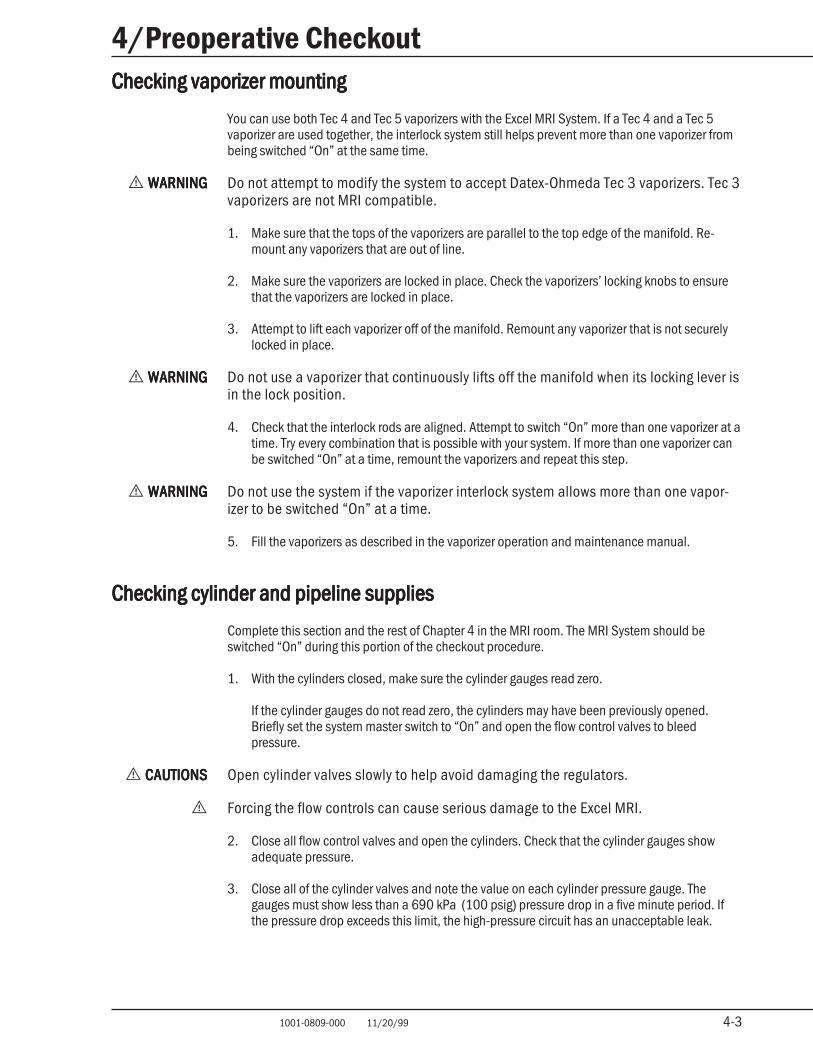
Checking vaporizer mountingChecking vaporizer mountingChecking vaporizer mountingChecking vaporizer mountingChecking vaporizer mounting
You can use both Tec 4 and Tec 5 vaporizers with the Excel MRI System. If a Tec 4 and a Tec 5vaporizer are used together, the interlock system still helps prevent more than one vaporizer frombeing switched “On” at the same time.
w WARNINGWARNINGWARNINGWARNINGWARNING Do not attempt to modify the system to accept Datex-Ohmeda Tec 3 vaporizers. Tec 3vaporizers are not MRI compatible.
1. Make sure that the tops of the vaporizers are parallel to the top edge of the manifold. Re-mount any vaporizers that are out of line.
2. Make sure the vaporizers are locked in place. Check the vaporizers’ locking knobs to ensurethat the vaporizers are locked in place.
3. Attempt to lift each vaporizer off of the manifold. Remount any vaporizer that is not securelylocked in place.
w WARNINGWARNINGWARNINGWARNINGWARNING Do not use a vaporizer that continuously lifts off the manifold when its locking lever isin the lock position.
4. Check that the interlock rods are aligned. Attempt to switch “On” more than one vaporizer at atime. Try every combination that is possible with your system. If more than one vaporizer canbe switched “On” at a time, remount the vaporizers and repeat this step.
w WARNINGWARNINGWARNINGWARNINGWARNING Do not use the system if the vaporizer interlock system allows more than one vapor-izer to be switched “On” at a time.
5. Fill the vaporizers as described in the vaporizer operation and maintenance manual.
Checking cylinder and pipeline suppliesChecking cylinder and pipeline suppliesChecking cylinder and pipeline suppliesChecking cylinder and pipeline suppliesChecking cylinder and pipeline supplies
Complete this section and the rest of Chapter 4 in the MRI room. The MRI System should beswitched “On” during this portion of the checkout procedure.
1. With the cylinders closed, make sure the cylinder gauges read zero.
If the cylinder gauges do not read zero, the cylinders may have been previously opened.Briefly set the system master switch to “On” and open the flow control valves to bleedpressure.
w CAUTIONSCAUTIONSCAUTIONSCAUTIONSCAUTIONS Open cylinder valves slowly to help avoid damaging the regulators.
w Forcing the flow controls can cause serious damage to the Excel MRI.
2. Close all flow control valves and open the cylinders. Check that the cylinder gauges showadequate pressure.
3. Close all of the cylinder valves and note the value on each cylinder pressure gauge. Thegauges must show less than a 690 kPa (100 psig) pressure drop in a five minute period. Ifthe pressure drop exceeds this limit, the high-pressure circuit has an unacceptable leak.
4-4 1001-0809-000 11/20/99
4/Preoperative Checkout
4-4
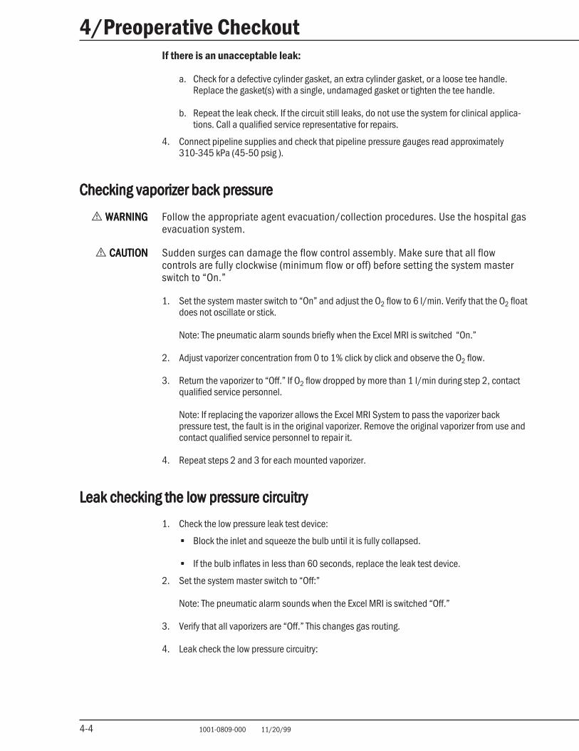
If there is an unacceptable leak:
a. Check for a defective cylinder gasket, an extra cylinder gasket, or a loose tee handle.Replace the gasket(s) with a single, undamaged gasket or tighten the tee handle.
b. Repeat the leak check. If the circuit still leaks, do not use the system for clinical applica-tions. Call a qualified service representative for repairs.
4. Connect pipeline supplies and check that pipeline pressure gauges read approximately310-345 kPa (45-50 psig ).
Checking vaporizer back pressureChecking vaporizer back pressureChecking vaporizer back pressureChecking vaporizer back pressureChecking vaporizer back pressure
w WARNINGWARNINGWARNINGWARNINGWARNING Follow the appropriate agent evacuation/collection procedures. Use the hospital gasevacuation system.
w CAUTIONCAUTIONCAUTIONCAUTIONCAUTION Sudden surges can damage the flow control assembly. Make sure that all flowcontrols are fully clockwise (minimum flow or off) before setting the system masterswitch to “On.”
1. Set the system master switch to “On” and adjust the O2 flow to 6 l/min. Verify that the O2 floatdoes not oscillate or stick.
Note: The pneumatic alarm sounds briefly when the Excel MRI is switched “On.”
2. Adjust vaporizer concentration from 0 to 1% click by click and observe the O2 flow.
3. Return the vaporizer to “Off.” If O2 flow dropped by more than 1 l/min during step 2, contactqualified service personnel.
Note: If replacing the vaporizer allows the Excel MRI System to pass the vaporizer backpressure test, the fault is in the original vaporizer. Remove the original vaporizer from use andcontact qualified service personnel to repair it.
4. Repeat steps 2 and 3 for each mounted vaporizer.
Leak checking the low pressure circuitryLeak checking the low pressure circuitryLeak checking the low pressure circuitryLeak checking the low pressure circuitryLeak checking the low pressure circuitry
1. Check the low pressure leak test device:
• Block the inlet and squeeze the bulb until it is fully collapsed.
• If the bulb inflates in less than 60 seconds, replace the leak test device.
2. Set the system master switch to “Off:”
Note: The pneumatic alarm sounds when the Excel MRI is switched “Off.”
3. Verify that all vaporizers are “Off.” This changes gas routing.
4. Leak check the low pressure circuitry:
4-5 1001-0809-000 11/20/99
4/Preoperative Checkout
4-5
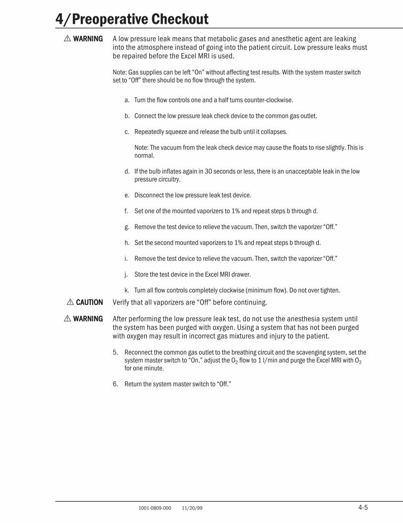
w WARNINGWARNINGWARNINGWARNINGWARNING A low pressure leak means that metabolic gases and anesthetic agent are leakinginto the atmosphere instead of going into the patient circuit. Low pressure leaks mustbe repaired before the Excel MRI is used.
Note: Gas supplies can be left “On” without affecting test results. With the system master switchset to “Off” there should be no flow through the system.
a. Turn the flow controls one and a half turns counter-clockwise.
b. Connect the low pressure leak check device to the common gas outlet.
c. Repeatedly squeeze and release the bulb until it collapses.
Note: The vacuum from the leak check device may cause the floats to rise slightly. This isnormal.
d. If the bulb inflates again in 30 seconds or less, there is an unacceptable leak in the lowpressure circuitry.
e. Disconnect the low pressure leak test device.
f. Set one of the mounted vaporizers to 1% and repeat steps b through d.
g. Remove the test device to relieve the vacuum. Then, switch the vaporizer “Off.”
h. Set the second mounted vaporizers to 1% and repeat steps b through d.
i. Remove the test device to relieve the vacuum. Then, switch the vaporizer “Off.”
j. Store the test device in the Excel MRI drawer.
k. Turn all flow controls completely clockwise (minimum flow). Do not over tighten.
w CAUTIONCAUTIONCAUTIONCAUTIONCAUTION Verify that all vaporizers are “Off” before continuing.
w WARNINGWARNINGWARNINGWARNINGWARNING After performing the low pressure leak test, do not use the anesthesia system untilthe system has been purged with oxygen. Using a system that has not been purgedwith oxygen may result in incorrect gas mixtures and injury to the patient.
5. Reconnect the common gas outlet to the breathing circuit and the scavenging system, set thesystem master switch to “On,” adjust the O2 flow to 1 l/min and purge the Excel MRI with O2for one minute.
6. Return the system master switch to “Off.”
4-6 1001-0809-000 11/20/99
4/Preoperative Checkout
4-6
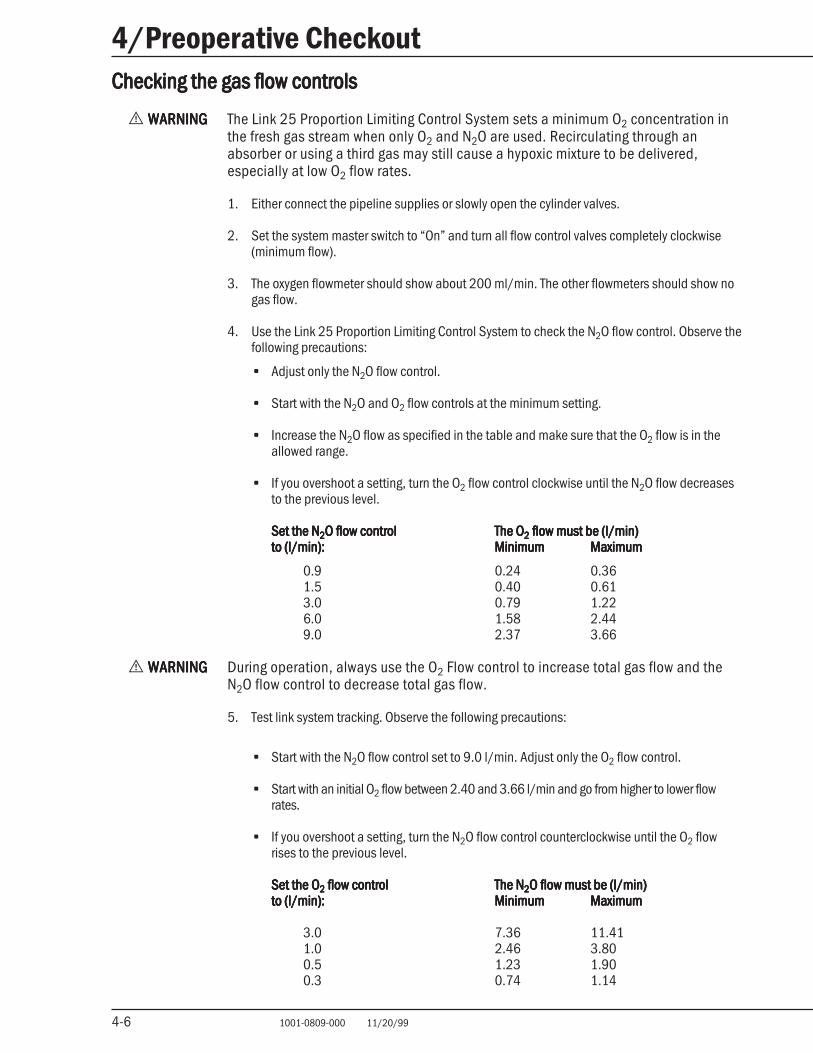
Checking the gas flow controlsChecking the gas flow controlsChecking the gas flow controlsChecking the gas flow controlsChecking the gas flow controls
w WARNINGWARNINGWARNINGWARNINGWARNING The Link 25 Proportion Limiting Control System sets a minimum O2 concentration inthe fresh gas stream when only O2 and N2O are used. Recirculating through anabsorber or using a third gas may still cause a hypoxic mixture to be delivered,especially at low O2 flow rates.
1. Either connect the pipeline supplies or slowly open the cylinder valves.
2. Set the system master switch to “On” and turn all flow control valves completely clockwise(minimum flow).
3. The oxygen flowmeter should show about 200 ml/min. The other flowmeters should show nogas flow.
4. Use the Link 25 Proportion Limiting Control System to check the N2O flow control. Observe thefollowing precautions:
• Adjust only the N2O flow control.
• Start with the N2O and O2 flow controls at the minimum setting.
• Increase the N2O flow as specified in the table and make sure that the O2 flow is in theallowed range.
• If you overshoot a setting, turn the O2 flow control clockwise until the N2O flow decreasesto the previous level.
Set the NSet the NSet the NSet the NSet the N22222O flow controlO flow controlO flow controlO flow controlO flow control The OThe OThe OThe OThe O22222 flow must be (l/min) flow must be (l/min) flow must be (l/min) flow must be (l/min) flow must be (l/min)to (l/min):to (l/min):to (l/min):to (l/min):to (l/min): MinimumMinimumMinimumMinimumMinimum MaximumMaximumMaximumMaximumMaximum
0.9 0.24 0.361.5 0.40 0.613.0 0.79 1.226.0 1.58 2.449.0 2.37 3.66
w WARNINGWARNINGWARNINGWARNINGWARNING During operation, always use the O2 Flow control to increase total gas flow and theN2O flow control to decrease total gas flow.
5. Test link system tracking. Observe the following precautions:
• Start with the N2O flow control set to 9.0 l/min. Adjust only the O2 flow control.
• Start with an initial O2 flow between 2.40 and 3.66 l/min and go from higher to lower flowrates.
• If you overshoot a setting, turn the N2O flow control counterclockwise until the O2 flowrises to the previous level.
Set the OSet the OSet the OSet the OSet the O22222 flow control flow control flow control flow control flow control The NThe NThe NThe NThe N22222O flow must be (l/min)O flow must be (l/min)O flow must be (l/min)O flow must be (l/min)O flow must be (l/min)to (l/min):to (l/min):to (l/min):to (l/min):to (l/min): MinimumMinimumMinimumMinimumMinimum MaximumMaximumMaximumMaximumMaximum
3.0 7.36 11.411.0 2.46 3.800.5 1.23 1.900.3 0.74 1.14
4-7 1001-0809-000 11/20/99
4/Preoperative Checkout
4-7
w WARNINGWARNINGWARNINGWARNINGWARNING Do not use the anesthesia system if the Datex-Ohmeda Link 25 Proportion LimitingControl System does not operate within permitted ranges. Using an incorrectlyoperating control system may result in incorrect gas mixtures, and injury to thepatient.
6. Adjust all of the gas flows to mid scale. While you are turning the flowmeter knobs, theflowmeter floats must move smoothly.
7. Shut “Off” the oxygen supply either by closing the oxygen cylinder valve, or by disconnectingthe oxygen pipeline supply. As pressure bleeds off:
• The oxygen-supply failure alarm must sound.
• All gas flow must fall to zero, with oxygen being the last gas to stop flowing.
8. Turn all of the flow control valve knobs completely clockwise to the minimum flow or closedposition. Do not over tighten the valves.
Breathing system checksBreathing system checksBreathing system checksBreathing system checksBreathing system checks
Note: Refer to the GMS Absorber Operation and Maintenance Manual for additional information. Acondensed version of the checkout is found on the back of the GMS Absorber.
1. Complete the GMS absorber checkout procedure.
2. Reconnect the unit for manual ventilation. Remove all occlusions from the circuit. Remove thetest plug from the ‘Y’ piece and connect a test lung. Press the Flush button to fill the breathingbag. Set the Bag/Ventilator switch to the “Bag” position and adjust the APL valve to relieve atthe desired pressure.
3. If the Excel MRI will not be used immediately, set the system master switch to “Off” and closeall gas cylinder valves.
5125 O5125 O5125 O5125 O5125 O22222 Monitor checks Monitor checks Monitor checks Monitor checks Monitor checks
1. Switch the O2 Monitor “On.”
Note: To avoid a long stabilization period, install a new cartridge (five minute stabilization time ifjust removed from package).
2. Set the alarm switch to 20% and the alarm switch to “00.”
3. Press down and release switch. Check that the “BATT OK” message appearsfor at least five seconds.
4. Press down and hold the switch. Check that:
• The alarm speaker beeps once.
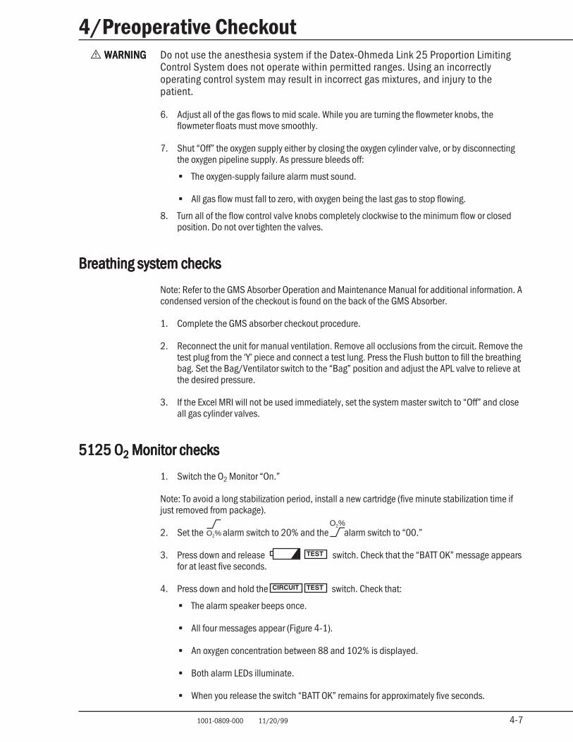
• All four messages appear (Figure 4-1).
• An oxygen concentration between 88 and 102% is displayed.
• Both alarm LEDs illuminate.
• When you release the switch “BATT OK” remains for approximately five seconds.
O2%O2%
4-8 1001-0809-000 11/20/99
4/Preoperative Checkout
4-8
Figure 4-1Circuit test display
5. Calibrate the O2 Monitor at 21% O2:
• Expose the O2 sensor to room air and allow the reading to stabilize for two minutes asroom air fills the sensor housing.
• If necessary, remove the two corner screws, open the lower front panel, and adjust thecalibration control (CAL) until the display reads 20%. Then, adjust the CAL control untilthe display just indicates 21%.
• If you cannot calibrate the O2 Monitor, replace the sensor cartridge. Refer to “O2 sensormaintenance,” in Chapter 5.
6. Set the alarm switch to 22% (1% over the display reading) and check that:
• The red LED flashes.
• LOW O2LOW O2LOW O2LOW O2LOW O2 appears in the display.
• A two-pitch alarm sounds.
• Pressing the å button stops the audible alarm for 30 seconds.
• Adjusting the alarm switch to 20% (1% below the display reading) stops the alarm.
7. Set the alarm switch to 20% (1% below the display reading) and check that:
• The yellow LED flashes.
• HIGH O2 appears in the display.
• An intermittent alarm sounds.
• Adjusting the alarm switch to 22% (1% over the display reading) stops the alarm.
8. At least once a month and following sensor cartridge replacement, calibrate the O2 Monitorfor 100% O2:
• Adjust the alarm switch to 00% (alarm disabled).
• Expose the O2 sensor to pure oxygen and allow the display to stabilize for two minutes asoxygen fills the patient circuit.
• Remove the two corner screws, open the lower front cover, and adjust the calibration control(CAL) until the display reads 99%.
• Expose the O2 sensor to room air and allow the display to stabilize for two minutes asroom air fills the sensor housing. If the final reading is outside the allowed range 21 ± 3%(18 to 24%), the sensor cartridge is no longer linear and must be replaced. Refer to “O2sensor maintenance,” in Chapter 5.
9. If the system will not be used immediately, switch the 5125 O2 Monitor “Off.”
MD
.07.
020
O2%
O2%
O2%
O2%
O2%
5-1 1001-0809-000 11/20/99 5-1
5/MaintenanceIn this sectionIn this sectionIn this sectionIn this sectionIn this section
Maintenance schedule 5-1Cleaning and sterilization 5-2
Cleaning 5-2
Sterilization 5-3
Special precautions for rubber articles 5-3O2 sensor maintenance 5-3
Installing a cartridge or disassembling the O2 sensor for cleaning 5-3
Cleaning and sterilization 5-6
Replacing the 5125 O2 Monitor battery 5-7
w WARNINGSWARNINGSWARNINGSWARNINGSWARNINGS This manual specifies Krytox® as an oxygen service lubricant. Do not use any lubri-cant on the Excel MRI that is not specifically approved for use on anesthesia oroxygen equipment. Oil and grease based lubricants burn violently and may explode inthe presence of oxygen.
w Static electricity is a fire hazard. Use only anti-static materials to cover the Excel MRISystem and its components.
Maintenance scheduleMaintenance scheduleMaintenance scheduleMaintenance scheduleMaintenance schedule
This schedule lists the minimum maintenance required, based on normal use and typical environmen-tal conditions. Heavier use or unusual environments may require more frequent maintenance. Beforeany cleaning or sterilization procedure check the section labeled “Cleaning and sterilization.”
Before each useBefore each useBefore each useBefore each useBefore each use
Perform preoperative checkout procedure (includes 21% O2 calibrations).
DailyDailyDailyDailyDaily
Clean the external surfaces.
Every two weeksEvery two weeksEvery two weeksEvery two weeksEvery two weeks
Drain and discard anesthetic agent from vaporizers. Less frequent changes may be required if theagent does not contain additives or stabilizing agents.
MonthlyMonthlyMonthlyMonthlyMonthly
Calibrate the O2 Monitor with 100% O2.
Apply Krytox to the threads on the yoke tee handle. Do not lubricate the absorber post assembly.
Every three monthsEvery three monthsEvery three monthsEvery three monthsEvery three months
Contact trained service personnel to perform a full checkout and scheduled service maintenanceon the Excel MRI System (Excel MRI, absorber, and O2 monitor).
AnnuallyAnnuallyAnnuallyAnnuallyAnnually
Replace the external vaporizer port o-rings.
Service Datex-Ohmeda Tec 4 vaporizers at an authorized Datex-Ohmeda service center.
Replace the O2 sensor cartridge. Cartridge life expectancy is one year at 50% O2 and 25°C(77°F). Different operating condition (higher O2 concentration, high temperature, etc.) canshorten cartridge life expectancy. Freezing may damage the sensor cartridge.® Krytox is a registered trademark of Dupont de Nemours E.I. & Company Inc.
5-2 1001-0809-000 11/20/99 5-2
5/MaintenanceEvery three yearsEvery three yearsEvery three yearsEvery three yearsEvery three years
Service Datex-Ohmeda Tec 5 vaporizers at an authorized Datex-Ohmeda service center.
As requiredAs requiredAs requiredAs requiredAs required
Install new cylinder gaskets.
Replace the absorbant in the GMS.
Replace the oxygen monitor battery.
Cleaning and sterilizationCleaning and sterilizationCleaning and sterilizationCleaning and sterilizationCleaning and sterilization
w CAUTIONSCAUTIONSCAUTIONSCAUTIONSCAUTIONS Do not sterilize the Excel MRI or the 5125 O2 Monitor.
w Following ethylene oxide sterilization, quarantine the items in a well ventilated areato allow dissipation of absorbed ethylene oxide gas. Follow the sterilizermanufacturer’s recommendations for specific sterilization periods.
Cleaning
Use this section as a quick reference once you are familiar with the cleaning procedures found inthe individual operation and maintenance manuals.
External surfacesExternal surfacesExternal surfacesExternal surfacesExternal surfaces
To clean external surfaces use a damp cloth and a mild detergent.
Use the minimum amount of liquid necessary since excess liquid may leak into monitoringconnections or other electrical components.
Sensor cleaning precautionsSensor cleaning precautionsSensor cleaning precautionsSensor cleaning precautionsSensor cleaning precautions
Wipe the O2 sensor cable and housing with a damp cloth. Never immerse the O2 sensor assemblyin liquid. Exposure to liquids can damage the electrical contacts.
The O2 sensor must be disassembled and the sensor cartridge removed for separate cleaning. Thehousing can be cleaned with a damp cloth (water, detergent solution or isopropyl alcohol).Corrosion from leaked sensor electrolyte can be removed with white vinegar under a fume hood.
The O2 sensor cartridge contains an electrolyte (caustic). It can be wiped clean with a damp cloth(water, liquid disinfectant, or white vinegar; do not use alcohols). Special precautions are re-quired. Refer to the “O2 sensor maintenance” section in this chapter for detailed instructions.
Precautions for painted, metal, or plastic surfacesPrecautions for painted, metal, or plastic surfacesPrecautions for painted, metal, or plastic surfacesPrecautions for painted, metal, or plastic surfacesPrecautions for painted, metal, or plastic surfaces
Do not use abrasive cleaners. They can mar the finish.
Do not use anesthetic agent or glass cleaners on plastic or painted surfaces. They can mar thesurface finish.
Always check cleaning product information to make sure that it is safe for aluminum, painted, orplastic surfaces.
5-3 1001-0809-000 11/20/99 5-3
5/MaintenanceSterilization
Use this section as a quick reference once you are familiar with the sterilization procedures foundin the individual operation and maintenance manuals.
Items that cannot be sterilized by any methodItems that cannot be sterilized by any methodItems that cannot be sterilized by any methodItems that cannot be sterilized by any methodItems that cannot be sterilized by any method
Excel MRI; 5125 O2 Monitor
Items that can be sterilized with ethylene oxideItems that can be sterilized with ethylene oxideItems that can be sterilized with ethylene oxideItems that can be sterilized with ethylene oxideItems that can be sterilized with ethylene oxide
These items can be sterilized with ethylene oxide: the front half of the oxygen sensor housing andrubber and plastic articles. Refer to individual operation and maintenance manuals for disassem-bly instructions and additional information.
Items that can be sterilized with liquid agentsItems that can be sterilized with liquid agentsItems that can be sterilized with liquid agentsItems that can be sterilized with liquid agentsItems that can be sterilized with liquid agents
The rubber and plastic articles can be sterilized with a cold germicidal solutions.
Special precautions for rubber articles
Rubber goods deteriorate over time and are considered expendable. The presence of oxygen,ozone, ether, mineral or vegetable oils, phenols, cresols, terpenes, hydrocarbon solvents,chlorinated hydrocarbons, esters, or oxidizing agents will hasten deterioration.
Check rubber articles regularly. Replace them when any of the following signs of deteriorationappear, swelling, tackiness, or cracking.
Conductive rubber goods loose their electrical conductivity with age.
To extend the useful life of rubber articles:
• Remove metal connectors immediately after use.
• Store rubber articles in the dark away from ozone sources (florescent light fixtures, electricmotors, and diathermy machines).
w WARNINGWARNINGWARNINGWARNINGWARNING Do not use talc, zinc stearate, calcium carbonate, corn starch or similar substancesto prevent tackiness on rubber articles. Any substances used could contaminate orirritate the patient’s respiratory tract.
OOOOO22222 sensor maintenance sensor maintenance sensor maintenance sensor maintenance sensor maintenance
Installing a cartridge or disassembling the O2 sensor for cleaning
w WARNINGWARNINGWARNINGWARNINGWARNING Use protective gloves and eyewear when you open the O2 sensor in case the cartridgeis leaking. The sensor cartridge contains an electrolyte (caustic).
After servicing the O2 sensor, complete the checkout procedure “5125 O2 Monitor checks” at theend of chapter 4.
5-4 1001-0809-000 11/20/99 5-4
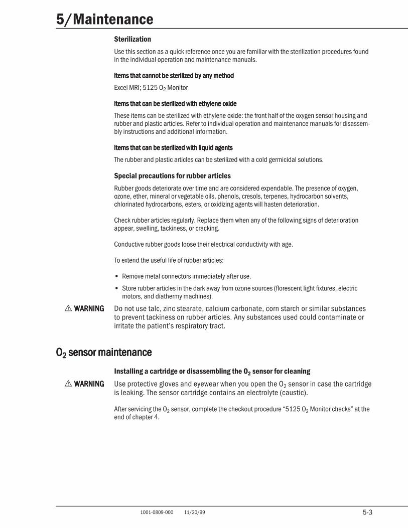
5/MaintenanceNote: The oxygen sensor cartridge is located inside the sensor housing. Handle the sensorcartridge with care to avoid damage.
Figure 5-1Hold the sensor housing, and depress the locking latch using a tool.
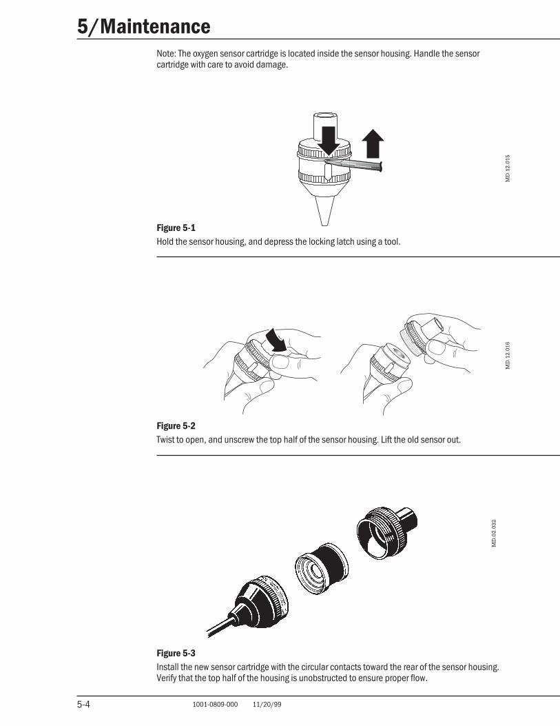
Figure 5-2Twist to open, and unscrew the top half of the sensor housing. Lift the old sensor out.
MD
.02.
032
MD
.12.
015
Figure 5-3Install the new sensor cartridge with the circular contacts toward the rear of the sensor housing.Verify that the top half of the housing is unobstructed to ensure proper flow.
MD
.12.
016
5-5 1001-0809-000 11/20/99 5-5
5/Maintenance
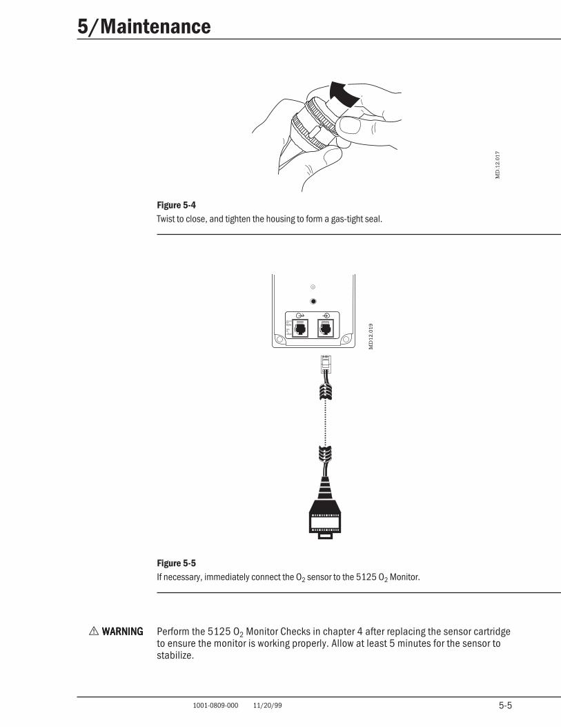
Figure 5-4Twist to close, and tighten the housing to form a gas-tight seal.
Figure 5-5If necessary, immediately connect the O2 sensor to the 5125 O2 Monitor.
w WARNINGWARNINGWARNINGWARNINGWARNING Perform the 5125 O2 Monitor Checks in chapter 4 after replacing the sensor cartridgeto ensure the monitor is working properly. Allow at least 5 minutes for the sensor tostabilize.
MD
12.0
19
MD
.12.
017
o2%
10 mVper
MinR
L20M
5-6 1001-0809-000 11/20/99 5-6
5/MaintenanceCleaning and sterilization
w WARNINGSWARNINGSWARNINGSWARNINGSWARNINGS Use protective gloves and eyewear when you open the O2 sensor in case the cartridgeis leaking. The sensor cartridge contains potassium acetate (caustic).
w Do not inhale any fumes generated by the oxygen sensor cleaning procedure. Suchfumes can cause respiratory system or skin damage. The sensor cartridge containspotassium acetate (caustic).
MD
.07.
009
MD
.12.
018
A
A CM
D.0
2.03
2
B
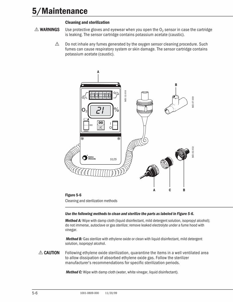
BFigure 5-6Cleaning and sterilization methods
Use the following methods to clean and sterilize the parts as labeled in Figure 5-6.
Method A: Wipe with damp cloth (liquid disinfectant, mild detergent solution, isopropyl alcohol);do not immerse, autoclave or gas sterilize; remove leaked electrolyte under a fume hood withvinegar.
Method B: Gas sterilize with ethylene oxide or clean with liquid disinfectant, mild detergentsolution, isopropyl alcohol.
w CAUTIONCAUTIONCAUTIONCAUTIONCAUTION Following ethylene oxide sterilization, quarantine the items in a well ventilated areato allow dissipation of absorbed ethylene oxide gas. Follow the sterilizermanufacturer’s recommendations for specific sterilization periods.
Method C: Wipe with damp cloth (water, white vinegar, liquid disinfectant).
5125
5-7 1001-0809-000 11/20/99 5-7
5/Maintenance
MD
.12.
014
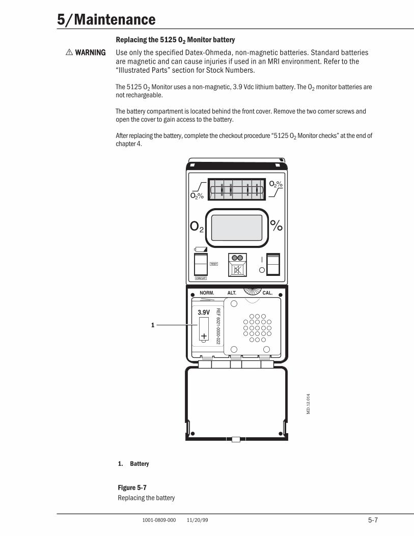
Replacing the 5125 O2 Monitor battery
w WARNINGWARNINGWARNINGWARNINGWARNING Use only the specified Datex-Ohmeda, non-magnetic batteries. Standard batteriesare magnetic and can cause injuries if used in an MRI environment. Refer to the“Illustrated Parts” section for Stock Numbers.
The 5125 O2 Monitor uses a non-magnetic, 3.9 Vdc lithium battery. The O2 monitor batteries arenot rechargeable.
The battery compartment is located behind the front cover. Remove the two corner screws andopen the cover to gain access to the battery.
After replacing the battery, complete the checkout procedure “5125 O2 Monitor checks” at the end ofchapter 4.
1. Battery
Figure 5-7Replacing the battery
1

5-8 1001-0809-000 11/20/99 5-8
5/MaintenanceNotes
6-1 1001-0809-000 11/20/99
6/Troubleshooting
6-1
In this sectionIn this sectionIn this sectionIn this sectionIn this section
Repair policy 6-1
Problems with the 5125 O2 Monitor 6-1
Calibration and drift 6-1
5125 O2 Monitor alarms 6-2
Pneumatics problems 6-3
Repair policyRepair policyRepair policyRepair policyRepair policy
Do not use malfunctioning equipment. Make all necessary repairs, or have the equipmentserviced by an Authorized Datex-Ohmeda Service Representative. After repair, test the equipmentto ensure that it is functioning properly, in accordance with the manufacturer’s published specifi-cations.
To ensure full reliability, have all repairs and service done by an Authorized Datex-Ohmeda ServiceRepresentative. If this cannot be done, replacement and maintenance of those parts listed in thismanual may be undertaken by a competent, trained individual having experience in the repair ofdevices of this nature.
w CAUTIONCAUTIONCAUTIONCAUTIONCAUTION No repair should ever be attempted by anyone not having experience in the repair ofdevices of this nature.
Replace damaged parts with components manufactured or sold by Datex-Ohmeda. Then test theunit to ascertain that it complies with the manufacturer’s published specifications.
Contact the nearest Datex-Ohmeda Service Center for service assistance. In all cases, other thanwhere Datex-Ohmeda’s warranty is applicable, repairs will be made at Datex-Ohmeda’s currentlist price for the replacement part(s) plus a reasonable labor charge.
Problems with the 5125 OProblems with the 5125 OProblems with the 5125 OProblems with the 5125 OProblems with the 5125 O22222 Monitor Monitor Monitor Monitor Monitor
Calibration and drift
Cannot calibrate monitorCannot calibrate monitorCannot calibrate monitorCannot calibrate monitorCannot calibrate monitor
Replace the O2 sensor cartridge. Refer to “O2 sensor maintenance,” in Chapter 5.
Drift in ODrift in ODrift in ODrift in ODrift in O22222 readings readings readings readings readings
Monitor O2 readings. If O2 readings fail to stabilize, replace the sensor cartridge.
6-2 1001-0809-000 11/20/99
6/Troubleshooting
6-2
5125 O2 Monitor alarms
Note: When one message covers multiple conditions, the distinguishing feature is highlighted.
HIGH O2HIGH O2HIGH O2HIGH O2HIGH O2
O2 Display Shows: O2 concentrationAlarm LED: Flashing YellowAlarm Silence: Until next occurrence
Measured O2 concentration is above the alarm limit. Set the alarm limit to “00” to disable high O2monitoring.
LOW BATTLOW BATTLOW BATTLOW BATTLOW BATT
(two alarms)(two alarms)(two alarms)(two alarms)(two alarms)
OOOOO22222 Display Shows: — blank — Display Shows: — blank — Display Shows: — blank — Display Shows: — blank — Display Shows: — blank —Alarm LED: Flashing YellowAlarm Tone: Intermittent
Immediate battery replacement required.
OOOOO22222 Display Shows: O Display Shows: O Display Shows: O Display Shows: O Display Shows: O22222 concentration concentration concentration concentration concentrationAlarm LED: Continuous YellowAlarm Tone: Three Beep Sequence
Battery is weak. Replace the battery before starting the case.
LOW OLOW OLOW OLOW OLOW O22222
OOOOO22222 Display Shows: Oxygen concentration Display Shows: Oxygen concentration Display Shows: Oxygen concentration Display Shows: Oxygen concentration Display Shows: Oxygen concentrationAlarm LED: Flashing RedAlarm Silence: 30 seconds
Measured oxygen concentration is below the alarm limit.
————— none none none none none—————
(three alarms)(three alarms)(three alarms)(three alarms)(three alarms)
OOOOO22222 Display Shows: Oxygen concentration Display Shows: Oxygen concentration Display Shows: Oxygen concentration Display Shows: Oxygen concentration Display Shows: Oxygen concentrationAlarm LED: Continuous YellowAlarm Tone: Three Beep Sequence
The low O2 alarm limit is set at or below 18%. This is not allowed. Set a higher low O2 alarm limit.
OOOOO22222 Display Shows: 00 Display Shows: 00 Display Shows: 00 Display Shows: 00 Display Shows: 00Alarm LED: Flashing YellowAlarm Tone: Intermittent
The O2 sensor is disconnected or has malfunctioned. If the sensor is connected, flex the cable tocheck for broken wires. If the cable appears to be intact, replace the sensor cartridge. If theproblem persists, contact qualified service personnel.
OOOOO22222 Display Shows: — blank — Display Shows: — blank — Display Shows: — blank — Display Shows: — blank — Display Shows: — blank —Alarm LED: Continuous YellowAlarm Tone: Continuous
Internal monitor malfunction. Contact qualified service personnel.
6-3 1001-0809-000 11/20/99
6/Troubleshooting
6-3
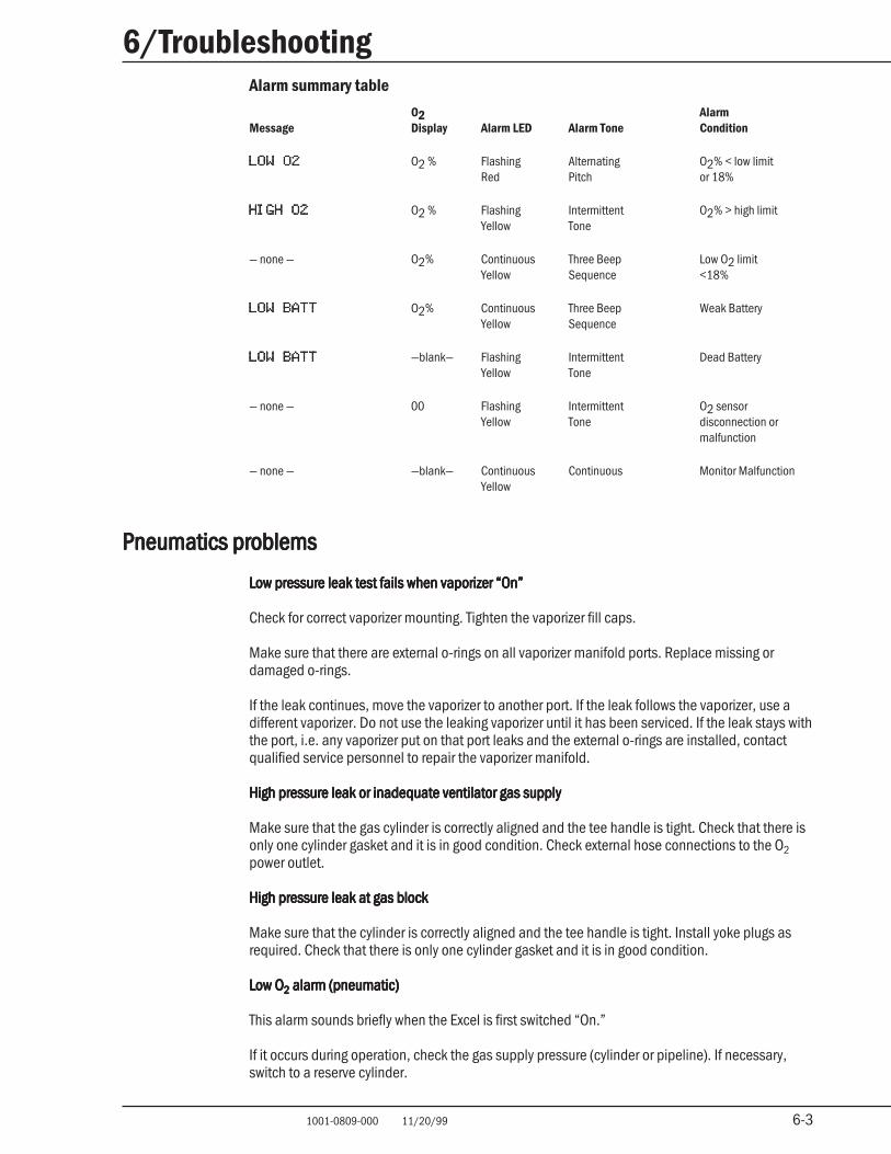
Alarm summary table
O2 AlarmMessage Display Alarm LED Alarm Tone Condition
LOW O2LOW O2LOW O2LOW O2LOW O2 O2 % Flashing Alternating O2% < low limitRed Pitch or 18%
HIGH O2HIGH O2HIGH O2HIGH O2HIGH O2 O2 % Flashing Intermittent O2% > high limitYellow Tone
— none — O2% Continuous Three Beep Low O2 limitYellow Sequence <18%
LOW BATTLOW BATTLOW BATTLOW BATTLOW BATT O2% Continuous Three Beep Weak BatteryYellow Sequence
LOW BATTLOW BATTLOW BATTLOW BATTLOW BATT —blank— Flashing Intermittent Dead BatteryYellow Tone
— none — 00 Flashing Intermittent O2 sensorYellow Tone disconnection or
malfunction
— none — —blank— Continuous Continuous Monitor MalfunctionYellow
Pneumatics problemsPneumatics problemsPneumatics problemsPneumatics problemsPneumatics problems
Low pressure leak test fails when vaporizer “On”Low pressure leak test fails when vaporizer “On”Low pressure leak test fails when vaporizer “On”Low pressure leak test fails when vaporizer “On”Low pressure leak test fails when vaporizer “On”
Check for correct vaporizer mounting. Tighten the vaporizer fill caps.
Make sure that there are external o-rings on all vaporizer manifold ports. Replace missing ordamaged o-rings.
If the leak continues, move the vaporizer to another port. If the leak follows the vaporizer, use adifferent vaporizer. Do not use the leaking vaporizer until it has been serviced. If the leak stays withthe port, i.e. any vaporizer put on that port leaks and the external o-rings are installed, contactqualified service personnel to repair the vaporizer manifold.
High pressure leak or inadequate ventilator gas supplyHigh pressure leak or inadequate ventilator gas supplyHigh pressure leak or inadequate ventilator gas supplyHigh pressure leak or inadequate ventilator gas supplyHigh pressure leak or inadequate ventilator gas supply
Make sure that the gas cylinder is correctly aligned and the tee handle is tight. Check that there isonly one cylinder gasket and it is in good condition. Check external hose connections to the O2power outlet.
High pressure leak at gas blockHigh pressure leak at gas blockHigh pressure leak at gas blockHigh pressure leak at gas blockHigh pressure leak at gas block
Make sure that the cylinder is correctly aligned and the tee handle is tight. Install yoke plugs asrequired. Check that there is only one cylinder gasket and it is in good condition.
Low OLow OLow OLow OLow O22222 alarm (pneumatic) alarm (pneumatic) alarm (pneumatic) alarm (pneumatic) alarm (pneumatic)
This alarm sounds briefly when the Excel is first switched “On.”
If it occurs during operation, check the gas supply pressure (cylinder or pipeline). If necessary,switch to a reserve cylinder.

6-4 1001-0809-000 11/20/99
6/Troubleshooting
6-4
Notes
7-1 1001-0809-000 11/20/99
7/Illustrated Parts
7-1
In this sectionIn this sectionIn this sectionIn this sectionIn this section
Excel specific parts 7-1
MRI Compatible accessories 7-1
5125 O2 Monitor accessories 7-2
Where to find additional part numbers 7-2
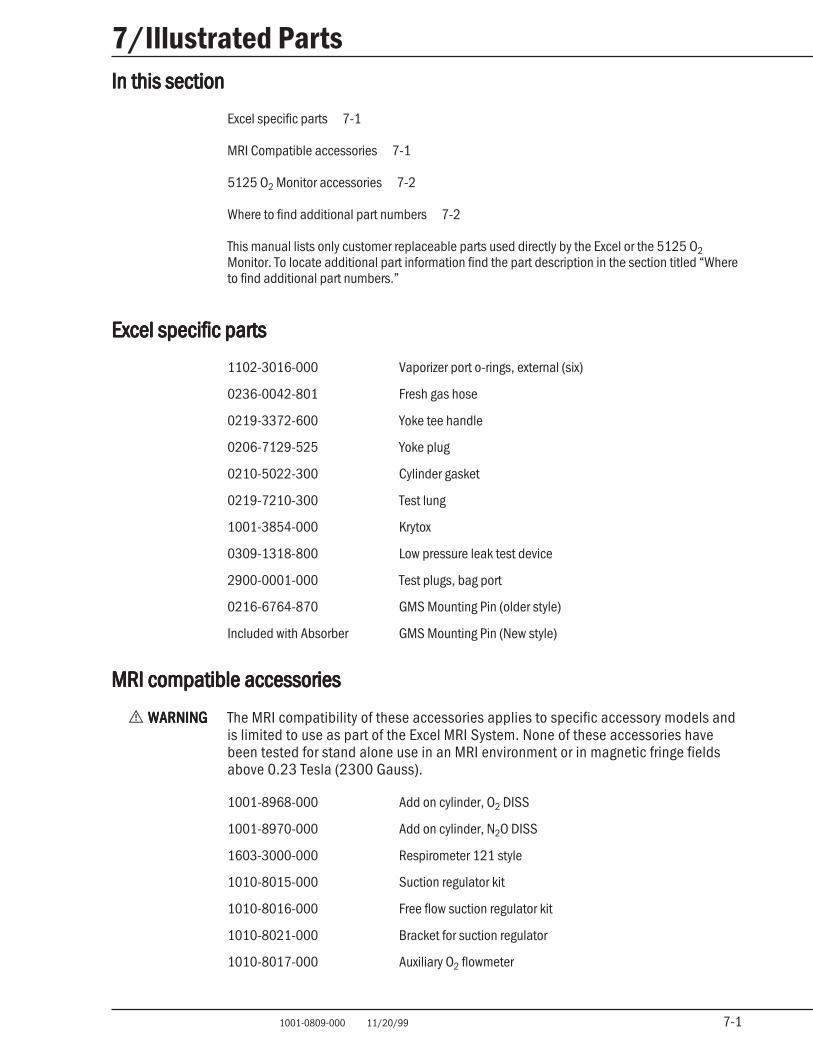
This manual lists only customer replaceable parts used directly by the Excel or the 5125 O2Monitor. To locate additional part information find the part description in the section titled “Whereto find additional part numbers.”
Excel specific partsExcel specific partsExcel specific partsExcel specific partsExcel specific parts
1102-3016-000 Vaporizer port o-rings, external (six)
0236-0042-801 Fresh gas hose
0219-3372-600 Yoke tee handle
0206-7129-525 Yoke plug
0210-5022-300 Cylinder gasket
0219-7210-300 Test lung
1001-3854-000 Krytox
0309-1318-800 Low pressure leak test device
2900-0001-000 Test plugs, bag port
0216-6764-870 GMS Mounting Pin (older style)
Included with Absorber GMS Mounting Pin (New style)
MRI compatible accessoriesMRI compatible accessoriesMRI compatible accessoriesMRI compatible accessoriesMRI compatible accessories
w WARNINGWARNINGWARNINGWARNINGWARNING The MRI compatibility of these accessories applies to specific accessory models andis limited to use as part of the Excel MRI System. None of these accessories havebeen tested for stand alone use in an MRI environment or in magnetic fringe fieldsabove 0.23 Tesla (2300 Gauss).
1001-8968-000 Add on cylinder, O2 DISS
1001-8970-000 Add on cylinder, N2O DISS
1603-3000-000 Respirometer 121 style
1010-8015-000 Suction regulator kit
1010-8016-000 Free flow suction regulator kit
1010-8021-000 Bracket for suction regulator
1010-8017-000 Auxiliary O2 flowmeter
7-2 1001-0809-000 11/20/99
7/Illustrated Parts
7-2
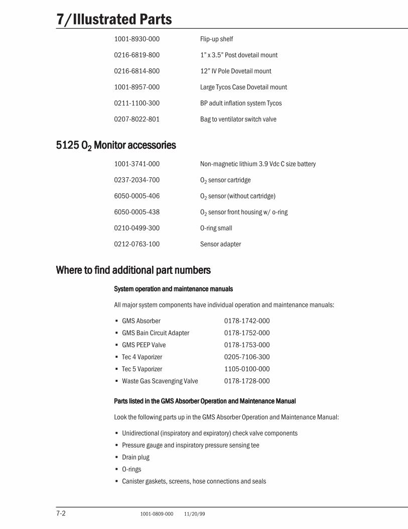
1001-8930-000 Flip-up shelf
0216-6819-800 1” x 3.5” Post dovetail mount
0216-6814-800 12” IV Pole Dovetail mount
1001-8957-000 Large Tycos Case Dovetail mount
0211-1100-300 BP adult inflation system Tycos
0207-8022-801 Bag to ventilator switch valve
5125 O5125 O5125 O5125 O5125 O22222 Monitor accessories Monitor accessories Monitor accessories Monitor accessories Monitor accessories
1001-3741-000 Non-magnetic lithium 3.9 Vdc C size battery
0237-2034-700 O2 sensor cartridge
6050-0005-406 O2 sensor (without cartridge)
6050-0005-438 O2 sensor front housing w/ o-ring
0210-0499-300 O-ring small
0212-0763-100 Sensor adapter
Where to find additional part numbersWhere to find additional part numbersWhere to find additional part numbersWhere to find additional part numbersWhere to find additional part numbers
System operation and maintenance manualsSystem operation and maintenance manualsSystem operation and maintenance manualsSystem operation and maintenance manualsSystem operation and maintenance manuals
All major system components have individual operation and maintenance manuals:
• GMS Absorber 0178-1742-000
• GMS Bain Circuit Adapter 0178-1752-000
• GMS PEEP Valve 0178-1753-000
• Tec 4 Vaporizer 0205-7106-300
• Tec 5 Vaporizer 1105-0100-000
• Waste Gas Scavenging Valve 0178-1728-000
Parts listed in the GMS Absorber Operation and Maintenance ManualParts listed in the GMS Absorber Operation and Maintenance ManualParts listed in the GMS Absorber Operation and Maintenance ManualParts listed in the GMS Absorber Operation and Maintenance ManualParts listed in the GMS Absorber Operation and Maintenance Manual
Look the following parts up in the GMS Absorber Operation and Maintenance Manual:
• Unidirectional (inspiratory and expiratory) check valve components
• Pressure gauge and inspiratory pressure sensing tee
• Drain plug
• O-rings
• Canister gaskets, screens, hose connections and seals
A-1 1001-0809-000 11/20/99
Appendix
A-1
In this sectionIn this sectionIn this sectionIn this sectionIn this section
Excel Pneumatics A-1
Excel MRI System Specifications A-4
Excel MRI PneumaticsExcel MRI PneumaticsExcel MRI PneumaticsExcel MRI PneumaticsExcel MRI Pneumatics
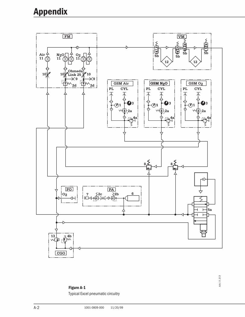
The Excel Gas Machine consists of the gas supply modules, the flow tubes and controls responsiblefor gas concentration, the vaporizer assemblies, and specialized alarm and “On” /“Off” functionsprovided by the oxygen supply. Most of the pneumatic circuitry is located underneath the tabletop.
The Excel MRI comes with gas supply modules for nitrous oxide, oxygen, and air.
Gas supply modules contain two parallel branches, pipeline and cylinder. The pipeline supplybranch consists of a filtered pipeline connection and a pipeline pressure gauge. The cylinder branchconsists of a filtered cylinder connection, a cylinder gauge, and a high pressure gas regulator thatreduces cylinder pressure to a nominal 311 kPa (45 psig). When only one source is connected orswitched “On,” check valves keep gas from leaking out through the unused branch. When bothpipeline and cylinder supplies are connected, make sure that the cylinder valve is closed. Other-wise, cylinder gas could be depleted since the pipeline pressure is almost the same as the regu-lated cylinder pressure. A pressure relief valve in each gas supply module limits maximum pressureto 518 kPa (75 psig).
Shut-off valves control the flow of the nitrous oxide and the air. When the system master switch isset to “Off,” these valves are closed. When the system master switch is set to “On,” the pilot oxygenpressure holds them open. As long as the pilot pressure remains above the critical level, approxi-mately 138 kPa (20 psig), the valves remain open. If the oxygen pilot pressure drops below thislevel, the shut-off valves close, stopping the flow of nitrous oxide and the air. You should notice thepilot oxygen flow through the oxygen flow tube whenever the system master switch is “On,” even ifthe oxygen flow control is turned completely clockwise (minimum flow).
Secondary regulators reduce the oxygen and nitrous oxide pressures to the levels required by theflow controls. The air goes directly from the primary regulator to the flow control. A gear linkage onthe nitrous oxide and oxygen flow control knobs helps limit the lowest O2 flow control setting to anominal 25% of the N2O flow control setting. A system of mechanical stops sets the maximumflows.
The mixed gas output of the flowmeter assembly goes through the selected vaporizer and into thepatient circuit. A pressure relief valve on the common gas outlet limits pressure to approximately27.6 to 38 kPa (4 to 5.5 psig) at 200 ml/min.
Pressing the “Flush” button connects pipeline or regulated cylinder oxygen directly to the gasmachine outlet regardless of the position of the system master switch.
The same pilot pressure that opens the shut-off valves pressurizes the alarm canister. A regulatorkeeps the oxygen in the canister as long as supply pressure exceeds approximately 207 kPa (30psig); range: 186 to 228 kPa (27 to 33 psig). If the oxygen supply pressure falls below this level,gas exits the canister through a reed alarm.
A-2 1001-0809-000 11/20/99
Appendix
A-2
Figure A-1Typical Excel pneumatic circuitry
AA
.11.
213
GSM Air
PL CYL
2a
4a
PL CYL
GSM N2OGSM N2O GSM O2PL CYL
13 4b
CGO
PA67
POO2
VM
12
5b
12
5b5b 5b
FM
Air11
OhmedaLink 25
9
2d
10
O211
N2O11
10 109
2d
1 11 13 3 3
2a2a
4a 4a
8 8
5a
2c 2b
A-3 1001-0809-000 11/20/99
Appendix
A-3
AA
.19.
041
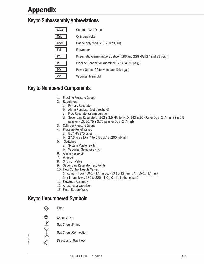
Key to Subassembly AbbreviationsKey to Subassembly AbbreviationsKey to Subassembly AbbreviationsKey to Subassembly AbbreviationsKey to Subassembly Abbreviations
CGO Common Gas Outlet
CYL Cylindery Yoke
GSM Gas Supply Module (O2, N2O, Air)
FM Flowmeter
PA Pneumatic Alarm (triggers betwen 186 and 228 kPa [27 and 33 psig])
PL Pipeline Connection (nominal 345 kPa [50 psig])
PO Power Outlet (O2 for ventilator Drive gas)
VM Vaporizer Manifold
Key to Numbered ComponentsKey to Numbered ComponentsKey to Numbered ComponentsKey to Numbered ComponentsKey to Numbered Components
1. Pipeline Pressure Gauge2. Regulators
a. Primary Regulatorb. Alarm Regulator (set threshold)c. Flow Regulator (alarm duration)d. Secondary Regulators (262 ± 3.5 kPa for N2O; 143 ± 26 kPa for O2 at 2 l/min [38 ± 0.5
psig for N2O; 20.75 ± 3.75 psig for O2 at 2 l/min])3. Cylinder Pressure Gauge4. Pressure Relief Valves
a. 517 kPa (75 psig)b. 27.6 to 38 kPa (4 to 5.5 psig) at 200 ml/min
5. Switchesa. System Master Switchb. Vaporizer Selector Switch
6. Alarm Reservoir7. Whistle8. Shut-Off Valve9. Secondary Regulator Test Points10. Flow Control Needle Valves
(maximum flows: 10-14 1/min O2; N2O 10-12 l/min; Air 15-17 1/min.)(minimum flows: 180 to 220 mil O2; 0 ml all other gases)
11. Flowtube Assembly12 Anesthesia Vaporizer13. Flush Button/Valve
Key to Unnumbered SymbolsKey to Unnumbered SymbolsKey to Unnumbered SymbolsKey to Unnumbered SymbolsKey to Unnumbered Symbols
Filter
Check Valve
Gas Circuit Fitting
Gas Circuit Connection
Direction of Gas Flow
A-4 1001-0809-000 11/20/99
Appendix
A-4
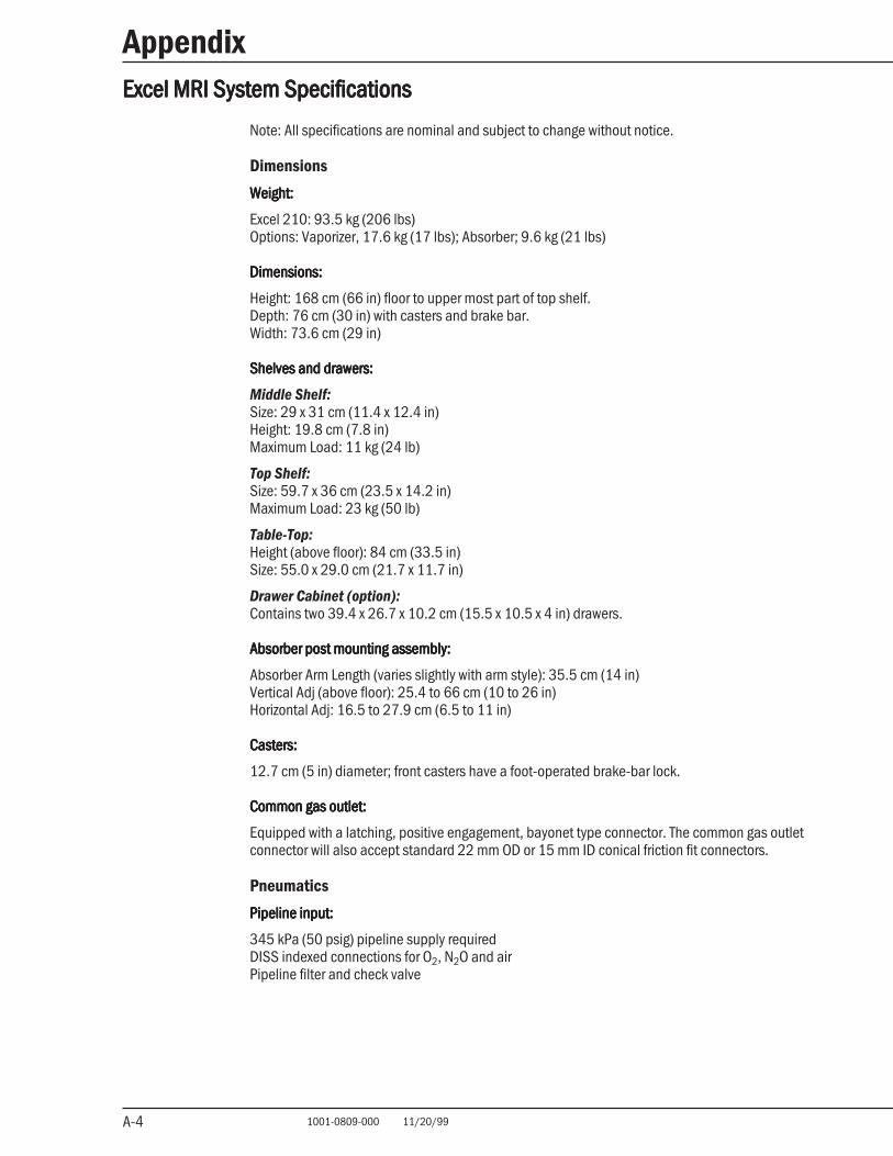
Excel MRI System SpecificationsExcel MRI System SpecificationsExcel MRI System SpecificationsExcel MRI System SpecificationsExcel MRI System Specifications
Note: All specifications are nominal and subject to change without notice.
Dimensions
Weight:Weight:Weight:Weight:Weight:
Excel 210: 93.5 kg (206 lbs)Options: Vaporizer, 17.6 kg (17 lbs); Absorber; 9.6 kg (21 lbs)
Dimensions:Dimensions:Dimensions:Dimensions:Dimensions:
Height: 168 cm (66 in) floor to upper most part of top shelf.Depth: 76 cm (30 in) with casters and brake bar.Width: 73.6 cm (29 in)
Shelves and drawers:Shelves and drawers:Shelves and drawers:Shelves and drawers:Shelves and drawers:
Middle Shelf:Size: 29 x 31 cm (11.4 x 12.4 in)Height: 19.8 cm (7.8 in)Maximum Load: 11 kg (24 lb)
Top Shelf:Size: 59.7 x 36 cm (23.5 x 14.2 in)Maximum Load: 23 kg (50 lb)
Table-Top:Height (above floor): 84 cm (33.5 in)Size: 55.0 x 29.0 cm (21.7 x 11.7 in)
Drawer Cabinet (option):Contains two 39.4 x 26.7 x 10.2 cm (15.5 x 10.5 x 4 in) drawers.
Absorber post mounting assembly:Absorber post mounting assembly:Absorber post mounting assembly:Absorber post mounting assembly:Absorber post mounting assembly:
Absorber Arm Length (varies slightly with arm style): 35.5 cm (14 in)Vertical Adj (above floor): 25.4 to 66 cm (10 to 26 in)Horizontal Adj: 16.5 to 27.9 cm (6.5 to 11 in)
Casters:Casters:Casters:Casters:Casters:
12.7 cm (5 in) diameter; front casters have a foot-operated brake-bar lock.
Common gas outlet:Common gas outlet:Common gas outlet:Common gas outlet:Common gas outlet:
Equipped with a latching, positive engagement, bayonet type connector. The common gas outletconnector will also accept standard 22 mm OD or 15 mm ID conical friction fit connectors.
Pneumatics
Pipeline input:Pipeline input:Pipeline input:Pipeline input:Pipeline input:
345 kPa (50 psig) pipeline supply requiredDISS indexed connections for O2, N2O and airPipeline filter and check valve
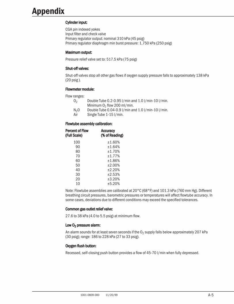
A-5 1001-0809-000 11/20/99
Appendix
A-5
Cylinder input:Cylinder input:Cylinder input:Cylinder input:Cylinder input:
CGA pin indexed yokesInput filter and check valvePrimary regulator output: nominal 310 kPa (45 psig)Primary regulator diaphragm min burst pressure: 1,750 kPa (250 psig)
Maximum output:Maximum output:Maximum output:Maximum output:Maximum output:
Pressure relief valve set to: 517.5 kPa (75 psig)
Shut-off valves:Shut-off valves:Shut-off valves:Shut-off valves:Shut-off valves:
Shut-off valves stop all other gas flows if oxygen supply pressure falls to approximately 138 kPa(20 psig ).
Flowmeter module:Flowmeter module:Flowmeter module:Flowmeter module:Flowmeter module:
Flow ranges:O2 Double Tube 0.2-0.95 l/min and 1.0 l/min-10 l/min.
Minimum O2 flow 200 ml/min.N2O Double Tube 0.04-0.9 l/min and 1.0 l/min-10 l/min.Air Single Tube 1-15 l/min.
Flowtube assembly calibration:Flowtube assembly calibration:Flowtube assembly calibration:Flowtube assembly calibration:Flowtube assembly calibration:
Percent of FlowPercent of FlowPercent of FlowPercent of FlowPercent of Flow AccuracyAccuracyAccuracyAccuracyAccuracy(Full Scale)(Full Scale)(Full Scale)(Full Scale)(Full Scale) (% of Reading)(% of Reading)(% of Reading)(% of Reading)(% of Reading)
100 ±1.60%90 ±1.64%80 ±1.70%70 ±1.77%60 ±1.86%50 ±2.00%40 ±2.20%30 ±2.53%20 ±3.20%10 ±5.20%
Note: Flowtube assemblies are calibrated at 20°C (68°F) and 101.3 kPa (760 mm Hg). Differentbreathing circuit pressures, barometric pressures or temperatures will affect flowtube accuracy. Insome cases, deviations due to different conditions may exceed the specified tolerances.
Common gas outlet relief valve:Common gas outlet relief valve:Common gas outlet relief valve:Common gas outlet relief valve:Common gas outlet relief valve:
27.6 to 38 kPa (4.0 to 5.5 psig) at minimum flow.
Low OLow OLow OLow OLow O22222 pressure alarm: pressure alarm: pressure alarm: pressure alarm: pressure alarm:
An alarm sounds for at least seven seconds if the O2 supply falls below approximately 207 kPa(30 psig); range: 186 to 228 kPa (27 to 33 psig).
Oxygen flush button:Oxygen flush button:Oxygen flush button:Oxygen flush button:Oxygen flush button:
Recessed, self-closing push button provides a flow of 45-70 l/min when fully depressed.
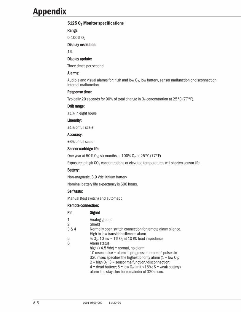
A-6 1001-0809-000 11/20/99
Appendix
A-6
5125 O2 Monitor specifications
Range:Range:Range:Range:Range:
0-100% O2
Display resolution:Display resolution:Display resolution:Display resolution:Display resolution:
1%
Display update:Display update:Display update:Display update:Display update:
Three times per second
Alarms:Alarms:Alarms:Alarms:Alarms:
Audible and visual alarms for: high and low O2, low battery, sensor malfunction or disconnection,internal malfunction.
Response time:Response time:Response time:Response time:Response time:
Typically 20 seconds for 90% of total change in O2 concentration at 25°C (77°F).
Drift range:Drift range:Drift range:Drift range:Drift range:
±1% in eight hours
Linearity:Linearity:Linearity:Linearity:Linearity:
±1% of full scale
Accuracy:Accuracy:Accuracy:Accuracy:Accuracy:
±3% of full scale
Sensor cartridge life:Sensor cartridge life:Sensor cartridge life:Sensor cartridge life:Sensor cartridge life:
One year at 50% O2; six months at 100% O2 at 25°C (77°F)
Exposure to high CO2 concentrations or elevated temperatures will shorten sensor life.
Battery:Battery:Battery:Battery:Battery:
Non-magnetic, 3.9 Vdc lithium battery
Nominal battery life expectancy is 600 hours.
Self tests:Self tests:Self tests:Self tests:Self tests:
Manual (test switch) and automatic
Remote connection:Remote connection:Remote connection:Remote connection:Remote connection:
PinPinPinPinPin SignalSignalSignalSignalSignal
1 Analog ground2 Shield3 & 4 Normally open switch connection for remote alarm silence.
High to low transition silences alarm.5 % O2; 10 mv = 1% O2 at 10 KΩ load impedance6 Alarm status:
high (>4.5 Vdc) = normal, no alarm;10 msec pulse = alarm in progress; number of pulses in320 msec specifies the highest priority alarm (1 = low O2;2 = high O2; 3 = sensor malfunction/disconnection;4 = dead battery; 5 = low O2 limit <18%; 6 = weak battery)alarm line stays low for remainder of 320 msec.
A-7 1001-0809-000 11/20/99
Appendix
A-7
This Product is sold by Datex-Ohmeda under the warranties set forth in the following paragraphs.Such warranties are extended only with respect to the purchase of this Product directly fromDatex-Ohmeda or Datex-Ohmeda’s Authorized Dealers as new merchandise and are extended tothe Buyer thereof, other than for the purpose of resale.
For a period of twelve (12) months from the date of original delivery to Buyer or to Buyer’s order,but in no event for a period of more than two years from the date of original delivery by Datex-Ohmeda to a Datex-Ohmeda Authorized Dealer, this Product, other than its expendable parts, iswarranted against functional defects in materials and workmanship and to conform to thedescription of the Product contained in this operation manual and accompanying labels and/orinserts, provided that the same is properly operated under the conditions of normal use, thatregular periodic maintenance and service is performed and that replacements and repairs aremade in accordance with the instructions provided. This same warranty is made for a period ofthirty (30) days with respect to expendable parts. The foregoing warranties shall not apply if theProduct has been repaired other than by Datex-Ohmeda or in accordance with written instructionsprovided by Datex-Ohmeda, or altered by anyone other than Datex-Ohmeda, or if the Product hasbeen subject to abuse, misuse, negligence, or accident.
Datex-Ohmeda’s sole and exclusive obligation and Buyer’s sole and exclusive remedy under theabove warranties is limited to repairing or replacing, free of charge, at Datex-Ohmeda’s option, aProduct, which is telephonically reported to the nearest Datex-Ohmeda Field Service SupportCenter and which, if so advised by Datex-Ohmeda, is thereafter returned with a statement of theobserved deficiency, not later than seven (7) days after the expiration date of the applicablewarranty, to the Datex-Ohmeda Service and Distribution Center during normal business hours,transportation charges prepaid, and which, upon Datex-Ohmeda’s examination, is found not toconform with above warranties. Datex-Ohmeda shall not be otherwise liable for any damagesincluding but not limited to incidental damages, consequential damages, or special damages.
There are no express or implied warranties which extend beyond the warranties hereinabove setforth. Datex-Ohmeda makes no warranty of merchantability or fitness for a particular purpose withrespect to the product or parts thereof.
Warranty
W-1
Datex-Ohmeda, Inc.Ohmeda DrivePO Box 7550Madison WI 53707-7550USATel 1 608 221 1551Fax 1 608 222 9147www.datex-ohmeda.com
1001 0809 00011 99 C 18 05 02Printed in USA©1999 Datex-Ohmeda, Inc. All rights reserved
Corporate Office
Datex-Ohmeda DivisionInstrumentarium Corp.PO Box 900FIN-00031 HelsinkiFinlandTel 358 10 394 11Fax 358 9 146 3310
North America
United StatesCustomer Service, Technical Supportand Distribution CenterDatex-Ohmeda, Inc.PO Box 7550Madison, WI 53707-7550, USATel 1 800 345 2700Fax 1 608 221 4384
Equipment Service CenterDatex-Ohmeda, Inc.1315 West Century DriveLouisville, CO 80027-9560, USATel 1 800 345 2755
CanadaDatex-Ohmeda (Canada) Inc.1093 Meyerside Drive, Unit 2Mississauga, OntarioL5T 1J6CanadaTel 1 800 268 1472Tel 1 905 565 8572Fax 1 905 565 8592
Asia/Pacific
ChinaDatex-Ohmeda Pte. Ltd.Room B416, COFCO Plaza8 Jianguomennei AvenueBeijing 100005, PR ChinaTel 86 10 6526 9773Fax 86 10 6526 0653Datex-Ohmeda Pte. Ltd.Room 1708, Yunlong MansionNo. 122 Luoguo StreetChengdu 610017, PR ChinaTel 86 28 661 4424Fax 86 28 676 2703Datex-Ohmeda Pte. Ltd.403 Huan Shi Dong RoadRoom 1602, GIE TowerGuangzhou, 510095, P R ChinaTel 86 20 8732 2521Fax 86 20 8732 2518
Datex-Ohmeda Pte. Ltd.Room 2509 Lippo PlazaNo. 222 Huaihai Road (M)Shanghai 200021, P.R. ChinaTel 8621 5382 5657Fax 8621 5382 1691Datex-Ohmeda Pte. Ltd.Room 809, Truroll PlazaWusheng RoadWuhan 430033, P R ChinaTel 86 27 8571 2536Fax 86 27 8571 2655
IndiaDatex-Ohmeda (India) Pvt. Ltd.Block EP & GP, Sector VPlot XI-16, Salt Lake CityCalcutta 700091IndiaTel 91 33 3574002Fax 91 33 3574001
IndonesiaDatex-Ohmeda Pte. Ltd.Wisma Danamon Aetna Life 19th FloorJln. Jend Sudirman Kav. 45-46Jakarta 12930, IndonesiaTel 62 21 575 0864Fax 62 21 575 0865
JapanDatex-Ohmeda K. K.TRC Annex 9F6-1-1 HeiwajimaOhta-ku, Tokyo 143-0006JapanTel 81 3 5763 6801Fax 81 3 5763 6838Datex-Ohmeda K. K.Technical CenterTRC A Bldg. AE 4-86-1-1 HeiwajimaOhta-ku, Tokyo 143-0006JapanTel 81 3 5763 6850Fax 81 3 5763 6852
KoreaDatex-Ohmeda Pte. Ltd.10th Floor, Sam Sung Building36 - 1, Yoido-Dong, Youngdeungpo-KuSeoul, KoreaTel 82 2 786 7421Fax 82 2 786 7420
MalaysiaDatex-Ohmeda Pte. Ltd.Level 2 Bangunan O'Connor13 Jalan 22346100 Petaling JayaSelangor, West MalaysiaTel 60 3 754 7872Fax 60 3 757 6948
SingaporeDatex-Ohmeda Pte. Ltd.152 Beach Road#12-05/07 Gateway EastSingapore 189721Tel 65 391 8618Fax 65 291 6618
ThailandDatex-Ohmeda Pte. Ltd.12th Floor (Unit F) Grand Amarin Tower1550 New Petchburi Road, Makasan,Rajathevi,Bangkok 10320, ThailandTel 66 2 2071012/13Fax 66 2 207 1014
Taiwan and PhilippinesDatex-Ohmeda Pte. Ltd.2nd Floor, No. 85, Chien-Kuo NorthRoad, Sec. 2Taipei, TaiwanRepublic of ChinaTel 886-2 2515-0457Fax 886-2 2501-9136
VietnamDatex-Ohmeda Pte. Ltd.522G Nguyen Tri Phuong St.Ho Chi Minh City, Dist. 10 VietnamTel 848 865 5875Fax 848 862 5501
AustraliaDatex-Ohmeda Pty. Ltd.Units 1 & 2149 Arthur StreetP O Box 356HomebushNSW 2140AustraliaTel 61 132 229Fax 61 297 461796
Europe
FranceDatex-Ohmeda S.A.S.Parc de Pissaloup, BP 108 Avenue Jean d’AlembertF-78191 Trappes-CédexFranceTel 33 1 30 68 60 00Fax 33 1 30 68 60 01Datex-Ohmeda S.A.S.17 rue Jean-Elysée DupuyF-69410 Champagne Au Mont d'OrFranceTel 33 1 30 68 60 00Fax 33 4 78 43 26 58
GermanyDatex-Ohmeda GmbHDr-Alfred-Herrhausen-Allee 24D-47228 DuisburgGermanyTel 49 2065 691-0Fax 49 2065 691-236
ItalyDatex-Ohmeda S.p.A.Via Cassanese 10020090 Segrate, MilanItalyTel 39 2 21693431Fax 39 2 26926226
NetherlandsDatex-Ohmeda B.V.Kantemarsweg 18Post Box 223870 CA HoevelakenNetherlandsTel 31 33 253 5404Fax 31 33 253 7223
SpainDatex-Ohmeda S.L.C/Manuel Tovar 2628034 MadridSpainTel 34 1 334 26 00Fax 34 1 358 12 84
United KingdomDatex-Ohmeda Ltd.Ohmeda House71 Great North RoadHatfield HertfordshireAL9 5EN EnglandTel 44 1707 263570Fax 44 1707 260191
Latin America, CaribbeanDatex-Ohmeda Latin America10685 North Kendall DriveMiami, FL 33176, USATel 1 305 273 9940Fax 1 305 273 4382
Middle EastDatex-OhmedaMiddle East OperationsP O Box 5527Dubai, United Arab EmiratesTel 97 14 822653Fax 97 14 822659