Embed Size (px)
Citation preview

Examples of Projects4th Training in Rio de Janeiro, BRA
6th-9th of May 2019Michael Trzesniowski, Thomas Lechner
"The European Commission support for the production of this publication does not constitute an endorsement of the contents which reflects the views only of the authors, and the Commission cannot be held responsible for any use which may be made of the information contained therein.“
FOR EDUCATIONAL PURPOSE ONLY

Content
1. Industrial Projects
2. R&D related Projects
3. Educational based Projects
Examples of Projects 2

1. Industrial Projects
Examples of Projects 3

Examples of Projects
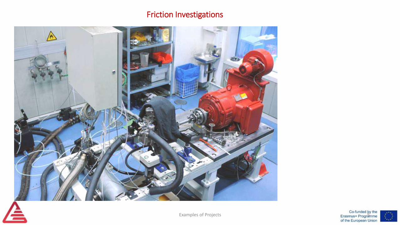
Friction Investigations
4
Examples of Projects
Friction Investigations
5
6Examples of Projects
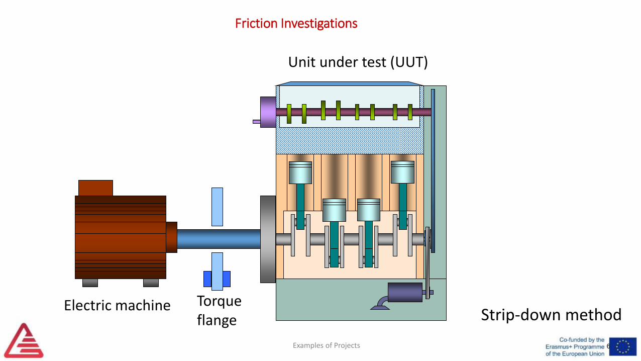
Friction Investigations
Strip-down methodElectric machine
Unit under test (UUT)
Torqueflange
Examples of Projects
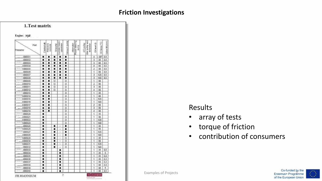
Results• array of tests• torque of friction• contribution of consumers
Friction Investigations
7
Examples of Projects
Friction Investigations
8
Examples of Projects
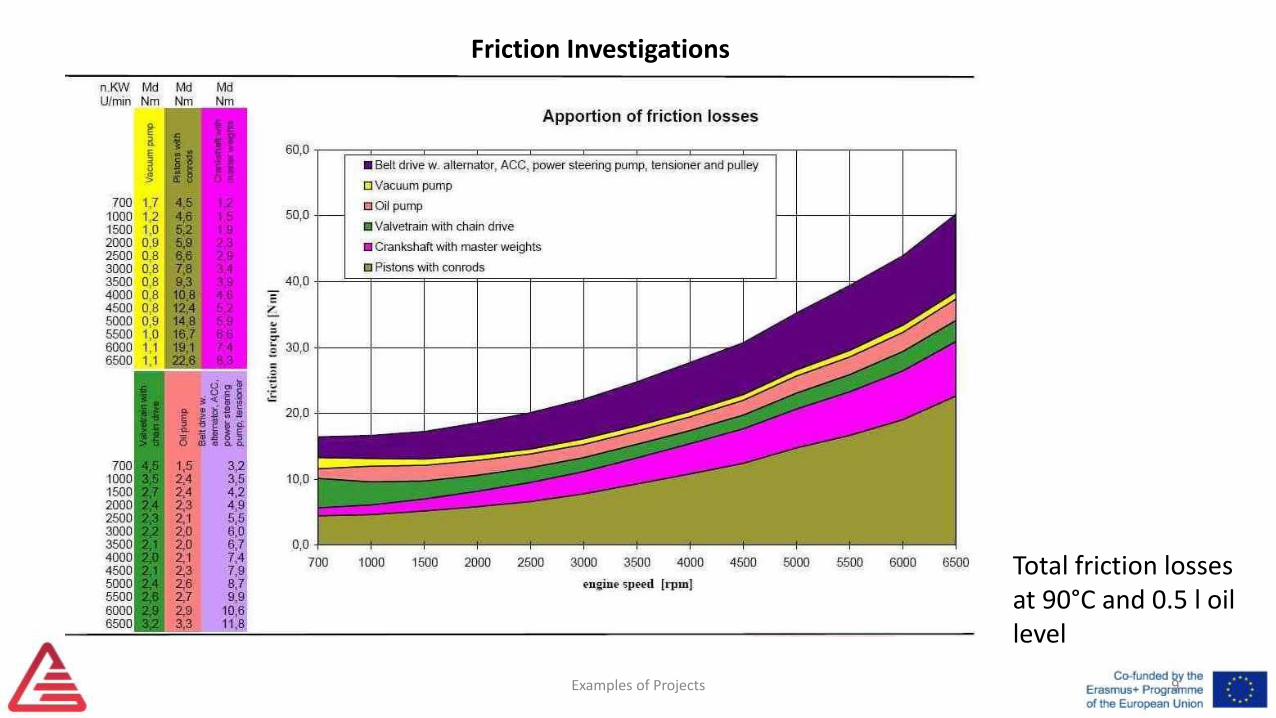
Friction Investigations
Total friction losses at 90°C and 0.5 l oil level
9
Examples of Projects
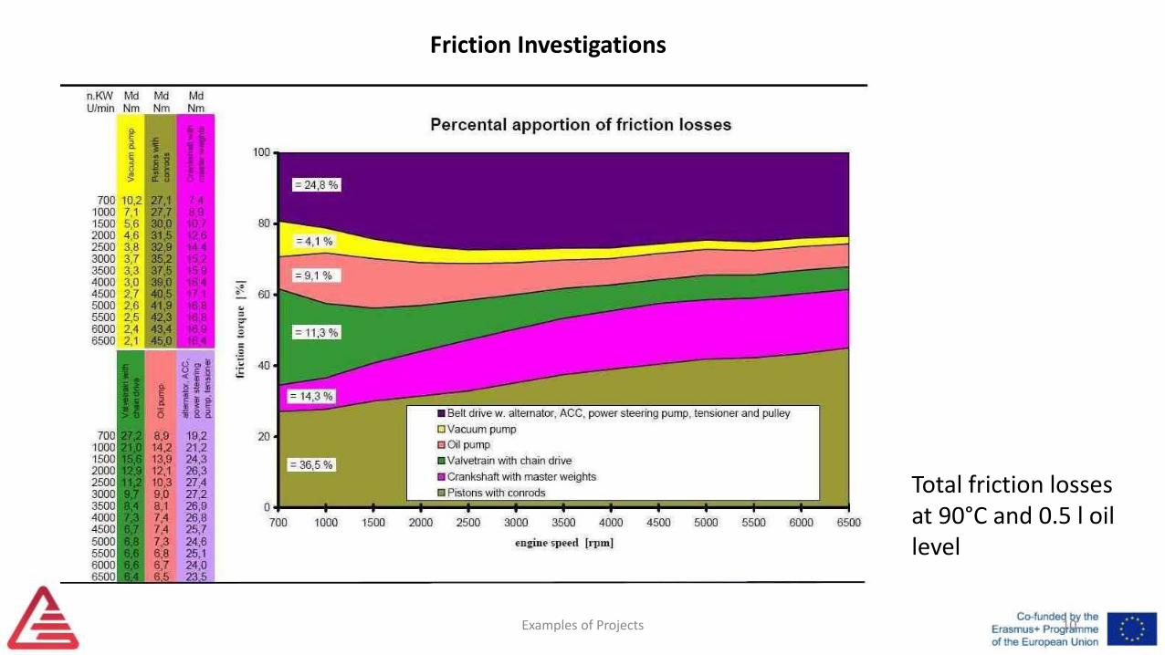
Friction Investigations
Total friction losses at 90°C and 0.5 l oil level
10

11
Evaporative Emissions Detection
Examples of Projects 12
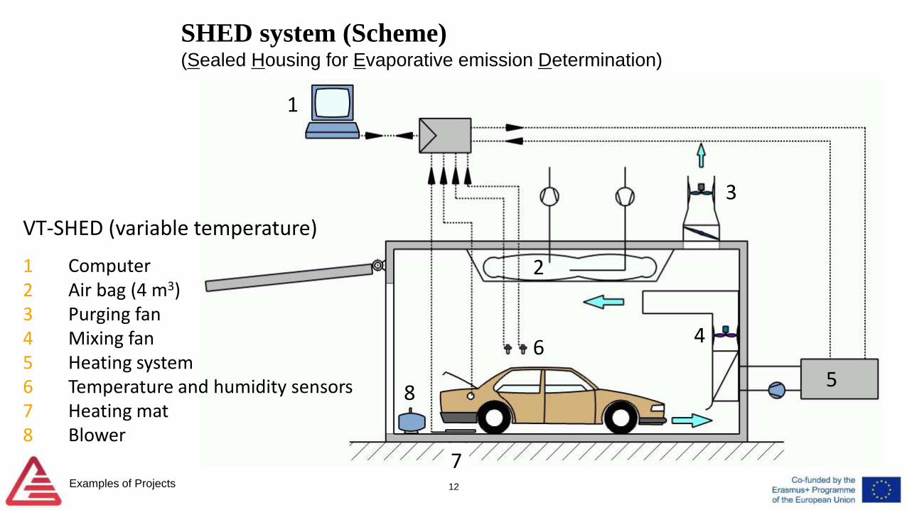
SHED system (Scheme)(Sealed Housing for Evaporative emission Determination)
1 Computer2 Air bag (4 m3)3 Purging fan4 Mixing fan5 Heating system6 Temperature and humidity sensors7 Heating mat8 Blower
1
2
3
4
5
6
7
8
VT-SHED (variable temperature)
Examples of Projects 13
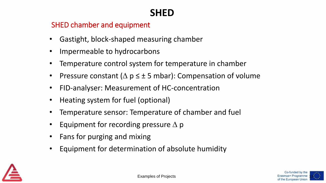
SHED chamber and equipment
• Gastight, block-shaped measuring chamber
• Impermeable to hydrocarbons
• Temperature control system for temperature in chamber
• Pressure constant ( p ≤ ± 5 mbar): Compensation of volume
• FID-analyser: Measurement of HC-concentration
• Heating system for fuel (optional)
• Temperature sensor: Temperature of chamber and fuel
• Equipment for recording pressure p
• Fans for purging and mixing
• Equipment for determination of absolute humidity
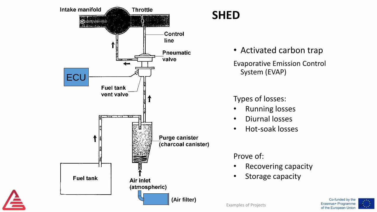
SHED
14
• Activated carbon trap
Evaporative Emission Control System (EVAP)
ECU
(Air filter)
Prove of:• Recovering capacity• Storage capacity
Types of losses:• Running losses• Diurnal losses• Hot-soak losses
SHED
Examples of Projects
Examples of Projects 15
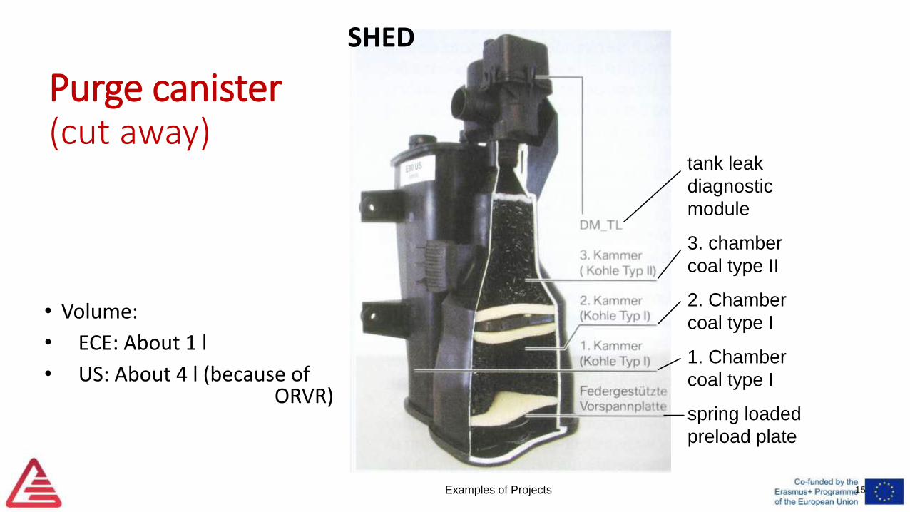
Purge canister(cut away)
• Volume:
• ECE: About 1 l
• US: About 4 l (because of ORVR)
tank leak
diagnostic
module
3. chamber
coal type II
2. Chamber
coal type I
1. Chamber
coal type I
spring loaded
preload plate
SHED
Examples of Projects16
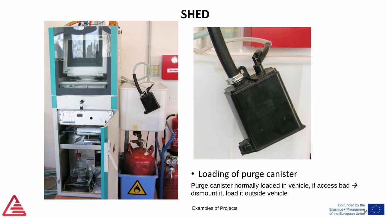
• Loading of purge canisterPurge canister normally loaded in vehicle, if access bad
dismount it, load it outside vehicle
SHED
Examples of Projects 17
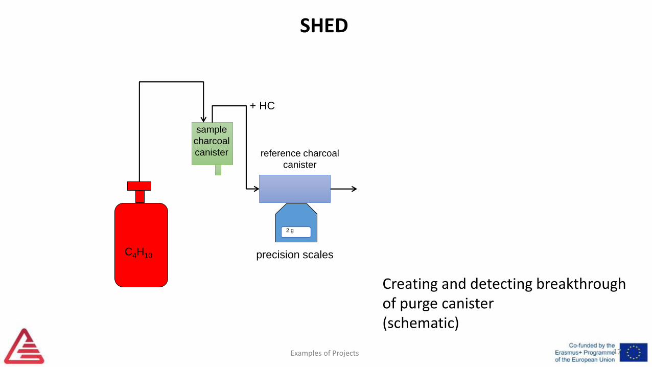
2 g
reference charcoal
canister
precision scalesC4H10
+ HC
sample
charcoal
canister
Creating and detecting breakthroughof purge canister(schematic)
SHED
Examples of Projects 18
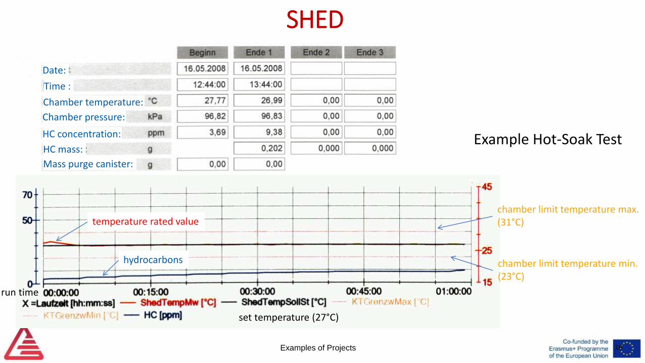
SHED
Example Hot-Soak Test
set temperature (27°C)
chamber limit temperature max.(31°C)
chamber limit temperature min.(23°C)
run time
temperature rated value
hydrocarbons
Date:
Time :
Chamber temperature:
Chamber pressure:
HC concentration:
HC mass:
Mass purge canister:
Examples of Projects 19
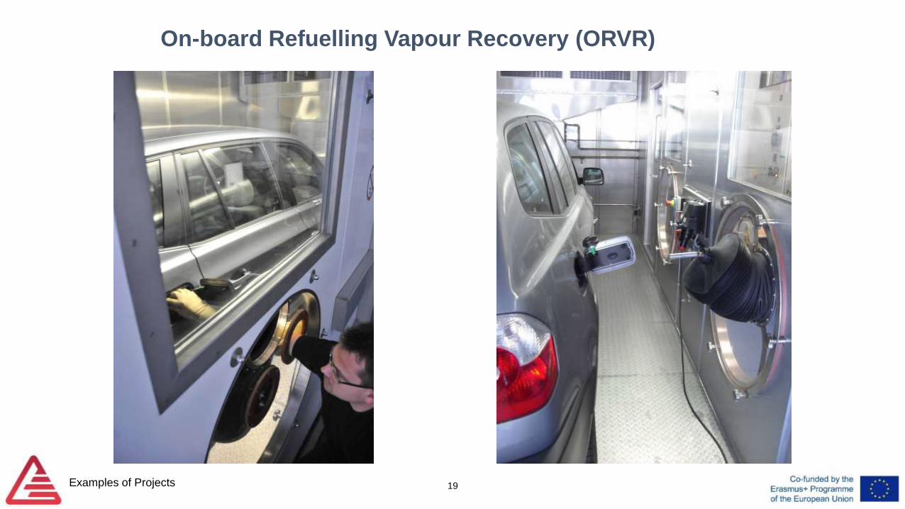
On-board Refuelling Vapour Recovery (ORVR)
Examples of Projects 20
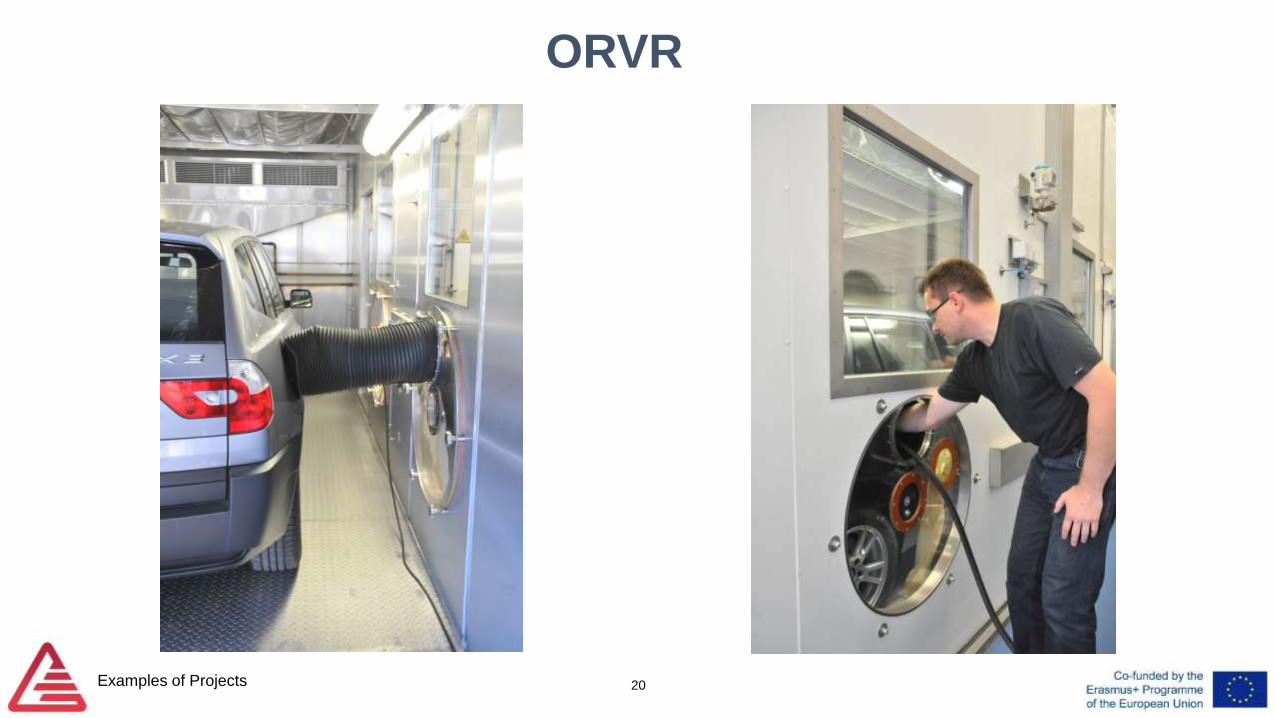
ORVR
Examples of Projects 21
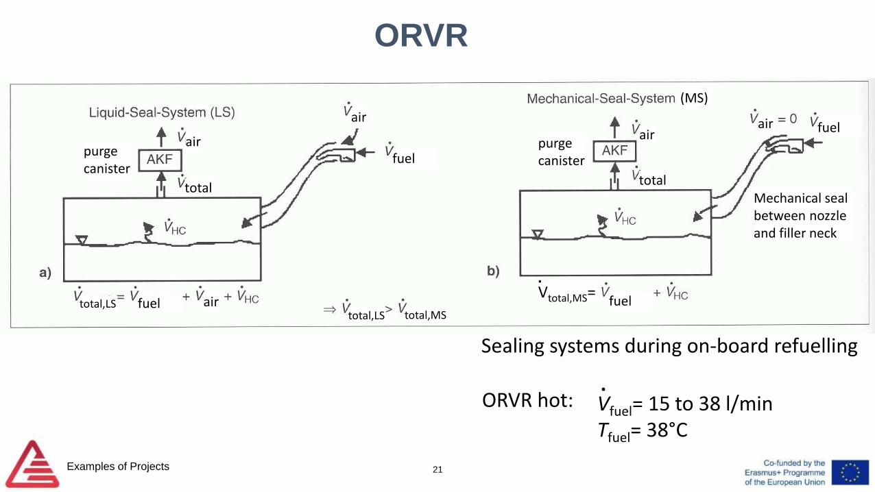
ORVR
Sealing systems during on-board refuelling
air
fuelair
total
air
total
air fuel
fuelfuel air
purge canister
purge canister
Mechanical seal between nozzle and filler neck
Vfuel= 15 to 38 l/minTfuel= 38°C
.ORVR hot:
total,LStotal,LS total,MS
(MS)
Vtotal,MS=.

2. R&D-related Projects
Examples of Projects 22
Examples of Projects
Real-time measurement of drive-line torque
23
Examples of Projects
Real-time measurement of drive-line torque
• Cooperation with engineering service provider
• Government-funded project
• Objectives:
•Simple and cost-effective solution for reading torque value in
•power train for control systems
•Useful for real-driving emissions (RDE) applications, energy
management of battery-electric vehicles (BEV), etc.
24
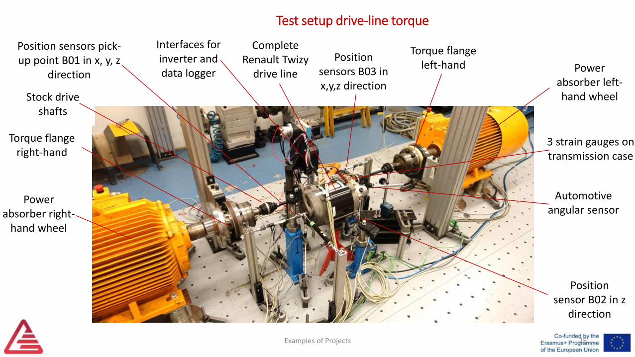
Test setup drive-line torque
Examples of Projects
Power absorber left-hand wheel
Power absorber right-
hand wheel
Torque flangeright-hand
Stock driveshafts
Position sensors pick-up point B01 in x, y, z
direction
Interfaces forinverter anddata logger
CompleteRenault Twizy
drive line
Position sensors B03 in x,y,z direction
Position sensor B02 in z
direction
Automotive angular sensor
Torque flangeleft-hand
3 strain gauges on transmission case
25
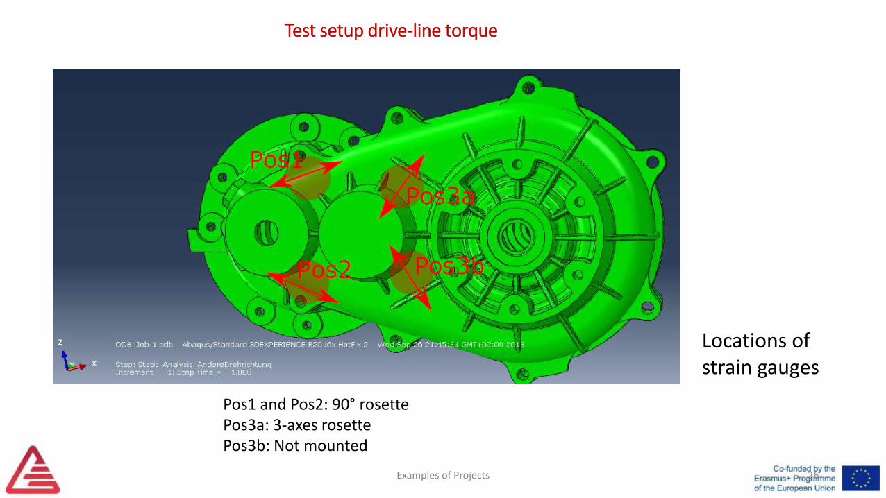
Test setup drive-line torque
Examples of Projects
Locations of strain gauges
Pos1 and Pos2: 90° rosettePos3a: 3-axes rosettePos3b: Not mounted
26
Tyre measurement
Examples of Projects 27
Examples of Projects
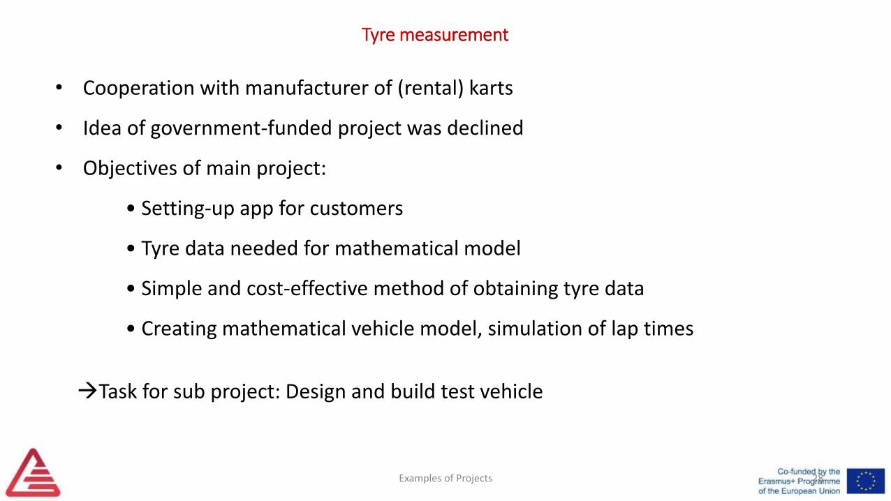
Tyre measurement
• Cooperation with manufacturer of (rental) karts
• Idea of government-funded project was declined
• Objectives of main project:
• Setting-up app for customers
• Tyre data needed for mathematical model
• Simple and cost-effective method of obtaining tyre data
• Creating mathematical vehicle model, simulation of lap times
28
Task for sub project: Design and build test vehicle
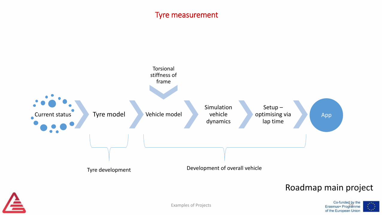
Current status Tyre model Vehicle modelSimulation
vehicle dynamics
Setup –optimising via
lap timeApp
29
Torsional stiffness of
frame
Development of overall vehicleTyre development
Roadmap main project
Tyre measurement
Examples of Projects
Examples of Projects
Tyre measurement
30
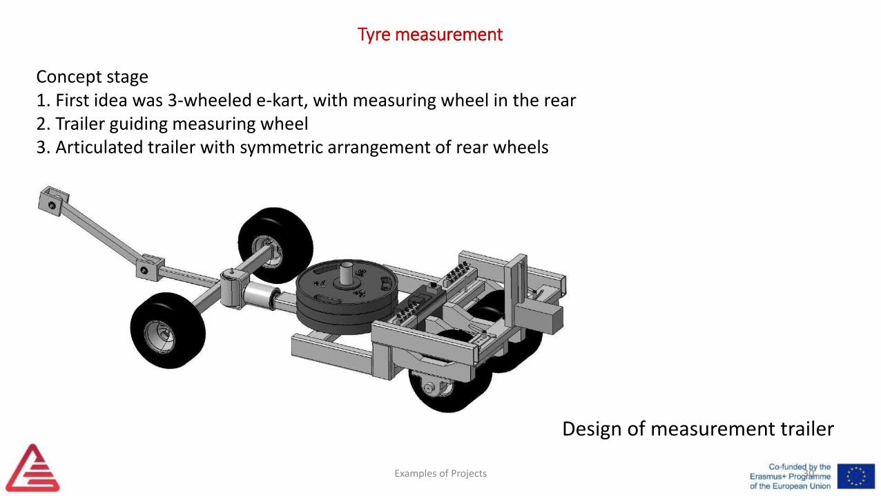
Design of measurement trailer
Concept stage1. First idea was 3-wheeled e-kart, with measuring wheel in the rear2. Trailer guiding measuring wheel3. Articulated trailer with symmetric arrangement of rear wheels
Examples of Projects
Tyre measurement
31
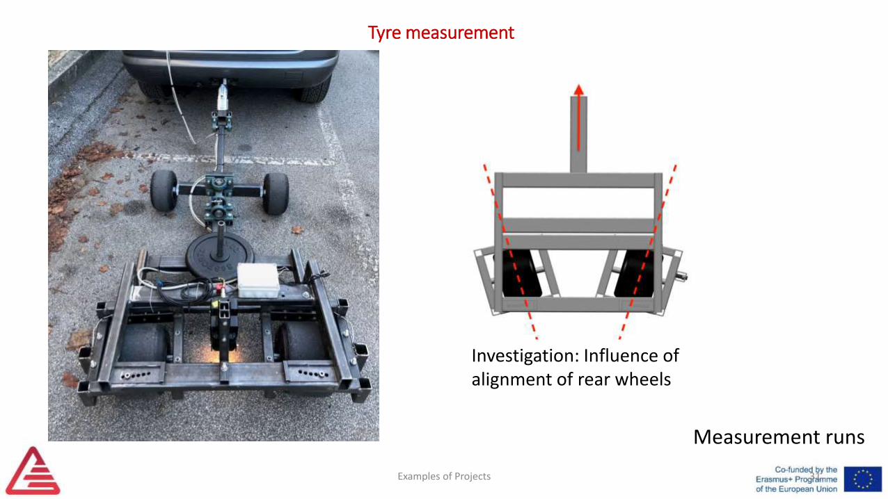
Measurement runs
Investigation: Influence of alignment of rear wheels
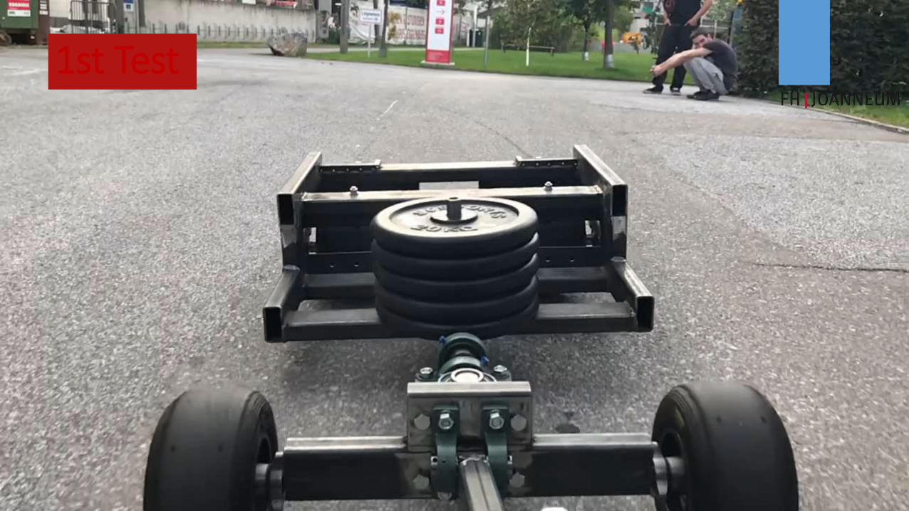
1st Test
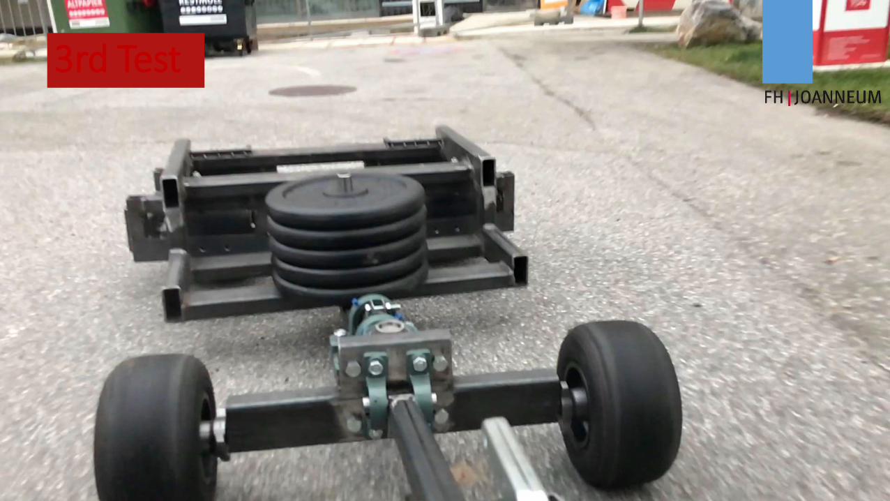
3rd Test
Examples of Projects
Tyre measurement
34
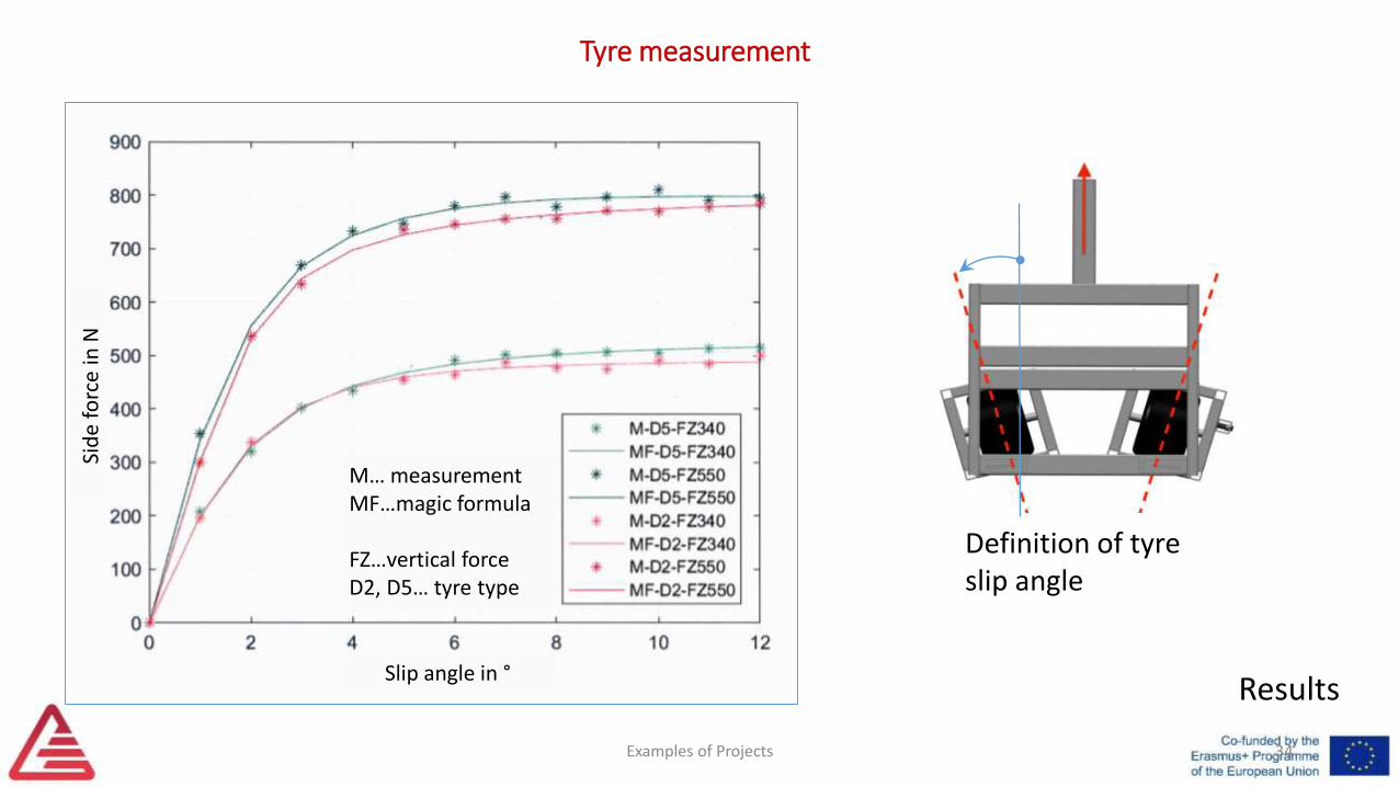
Results
Definition of tyre slip angle
Slip angle in °
Sid
e fo
rce
in N
M… measurementMF…magic formula
FZ…vertical forceD2, D5… tyre type
Examples of Projects 35
E-Drive Measurement
Examples of Projects 36
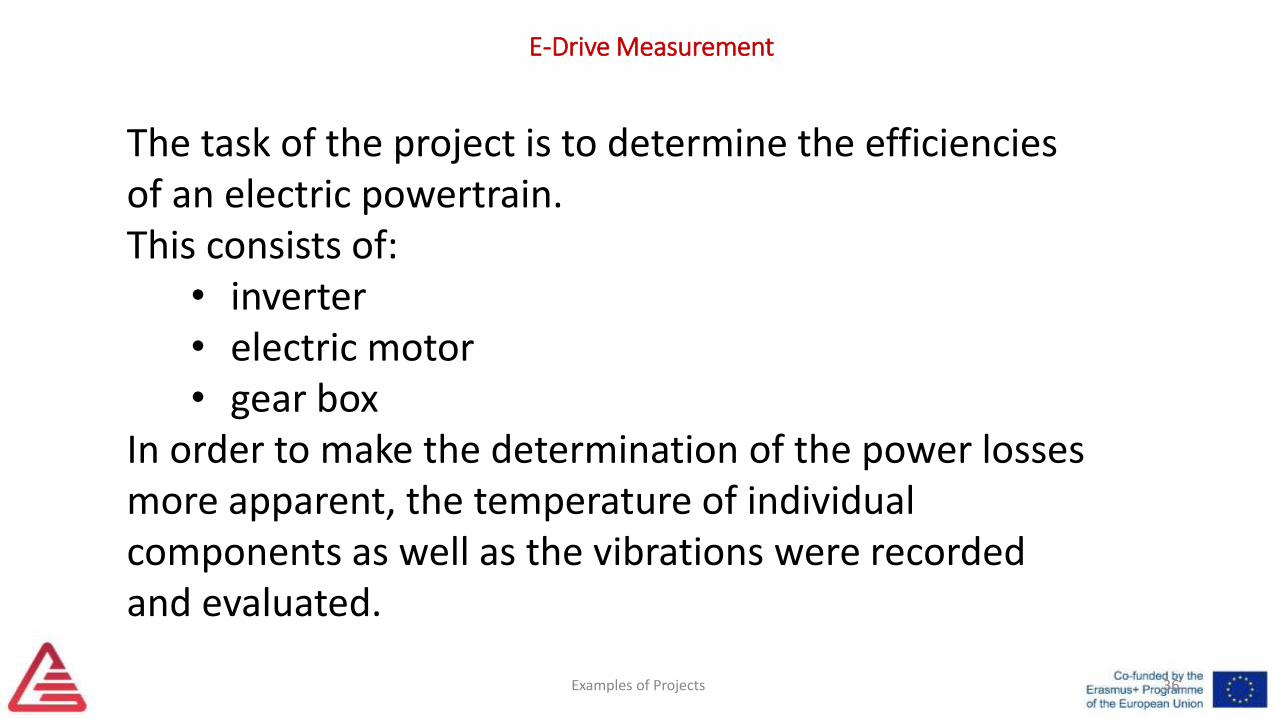
The task of the project is to determine the efficiencies of an electric powertrain. This consists of:
• inverter• electric motor• gear box
In order to make the determination of the power losses more apparent, the temperature of individual components as well as the vibrations were recorded and evaluated.
E-Drive Measurement
Examples of Projects
E-Drive Measurement
37
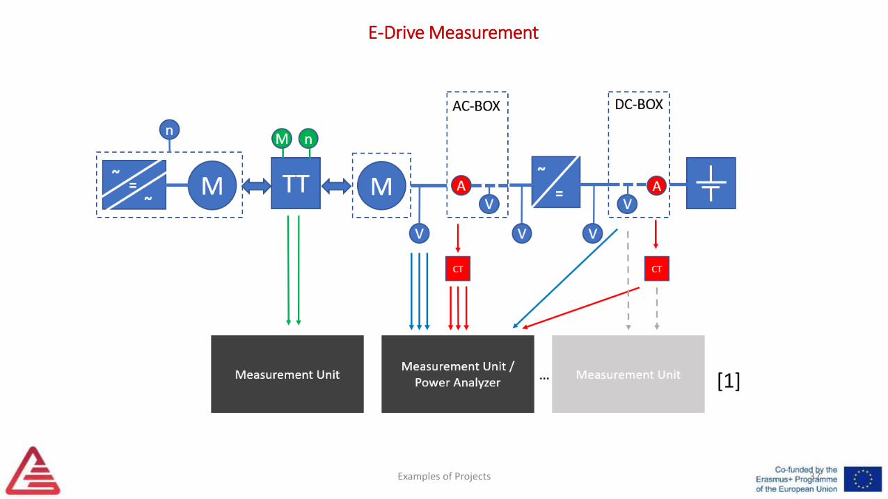
[1]
Examples of Projects 38
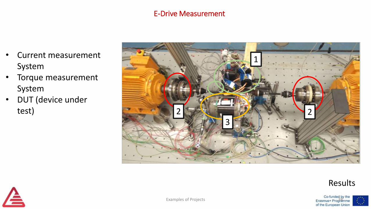
Results
E-Drive Measurement
• Current measurement System
• Torque measurement System
• DUT (device under test)
322
1
Examples of Projects 39
E-Drive Measurement
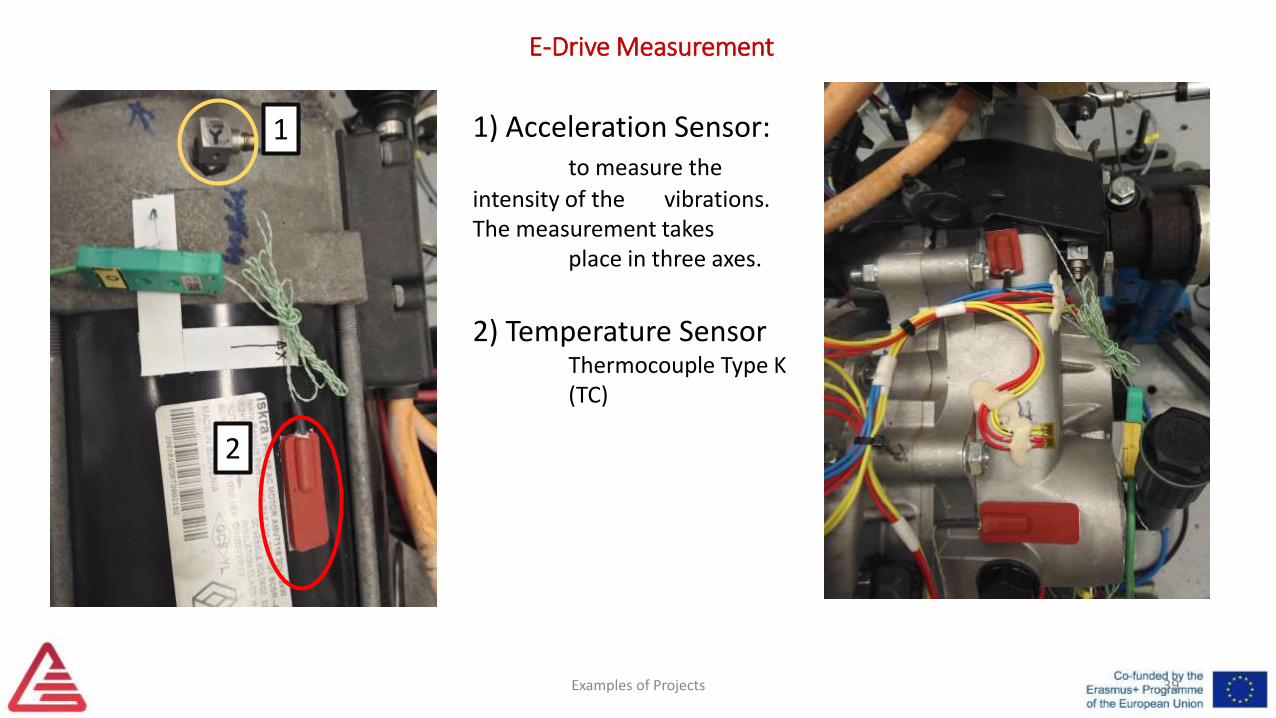
1) Acceleration Sensor:to measure the
intensity of the vibrations. The measurement takes
place in three axes.
2) Temperature SensorThermocouple Type K (TC)
1
2
Examples of Projects 40
E-Drive Measurement
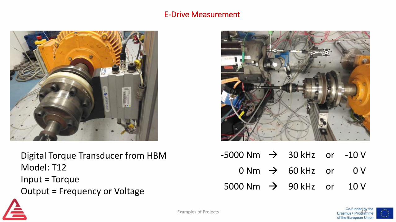
Digital Torque Transducer from HBMModel: T12Input = TorqueOutput = Frequency or Voltage
-5000 Nm 30 kHz or -10 V
0 Nm 60 kHz or 0 V
5000 Nm 90 kHz or 10 V
Examples of Projects 41
E-Drive Measurement
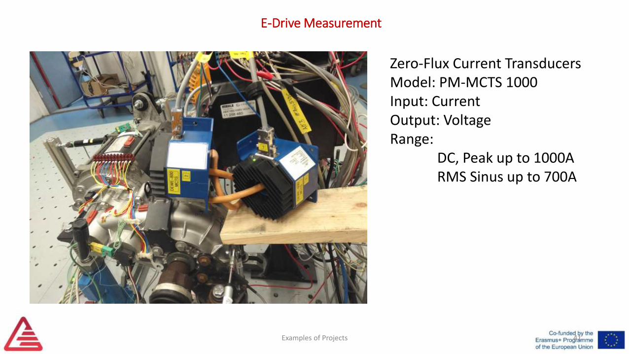
Zero-Flux Current Transducers Model: PM-MCTS 1000Input: CurrentOutput: VoltageRange:
DC, Peak up to 1000ARMS Sinus up to 700A
Examples of Projects 42
E-Drive Measurement
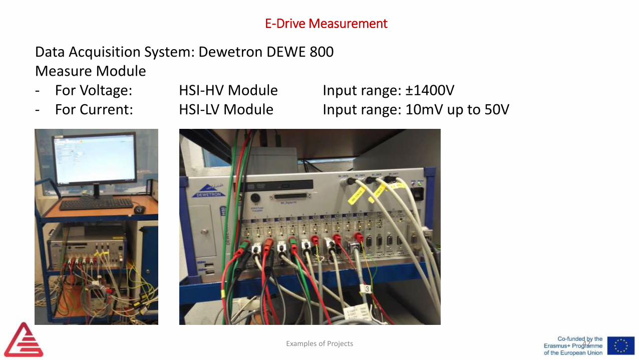
Data Acquisition System: Dewetron DEWE 800Measure Module- For Voltage: HSI-HV Module Input range: ±1400V- For Current: HSI-LV Module Input range: 10mV up to 50V
Examples of Projects 43
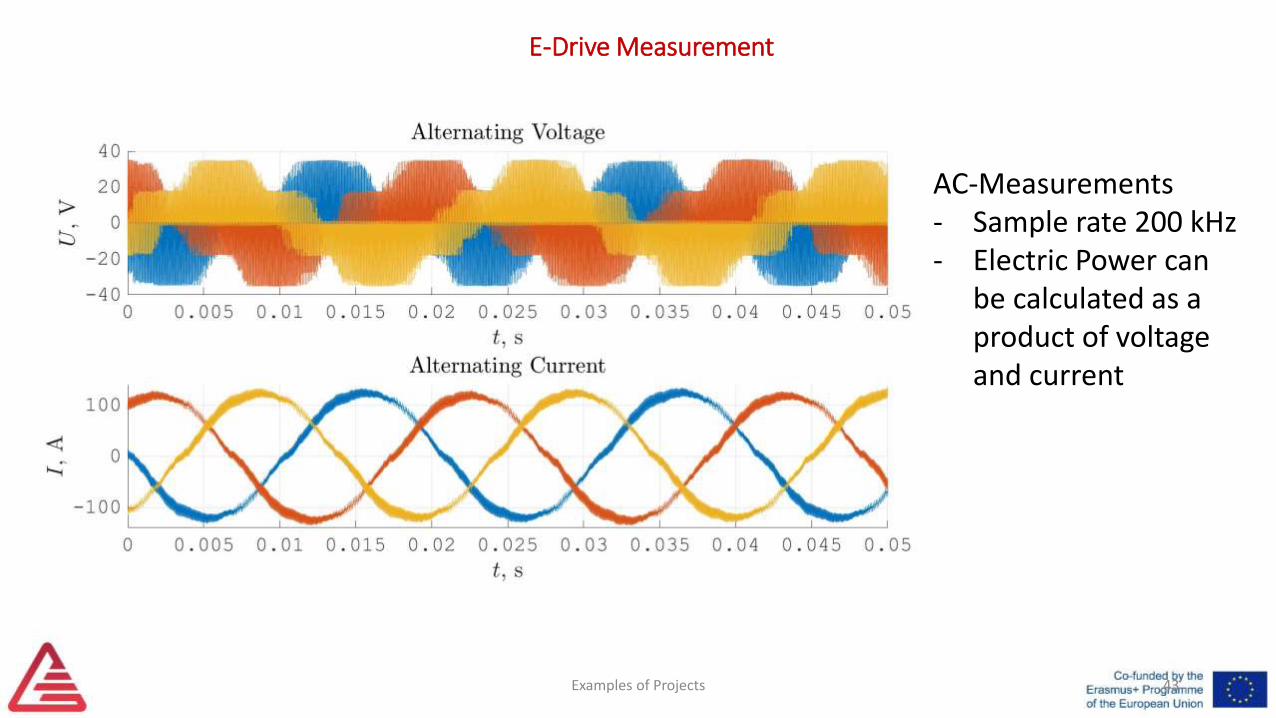
E-Drive Measurement
AC-Measurements- Sample rate 200 kHz- Electric Power can
be calculated as a product of voltage and current
Examples of Projects 44
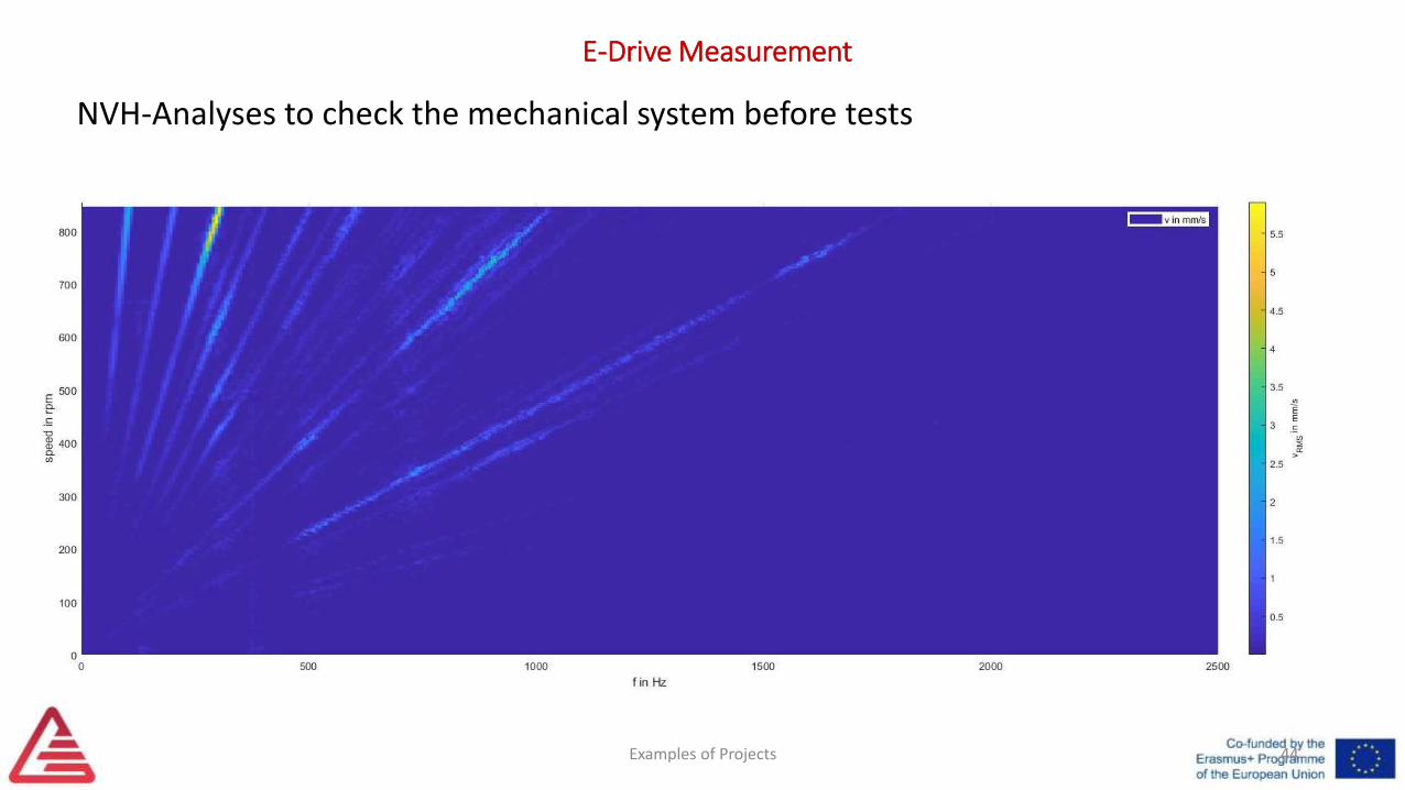
E-Drive Measurement
NVH-Analyses to check the mechanical system before tests
Examples of Projects 45
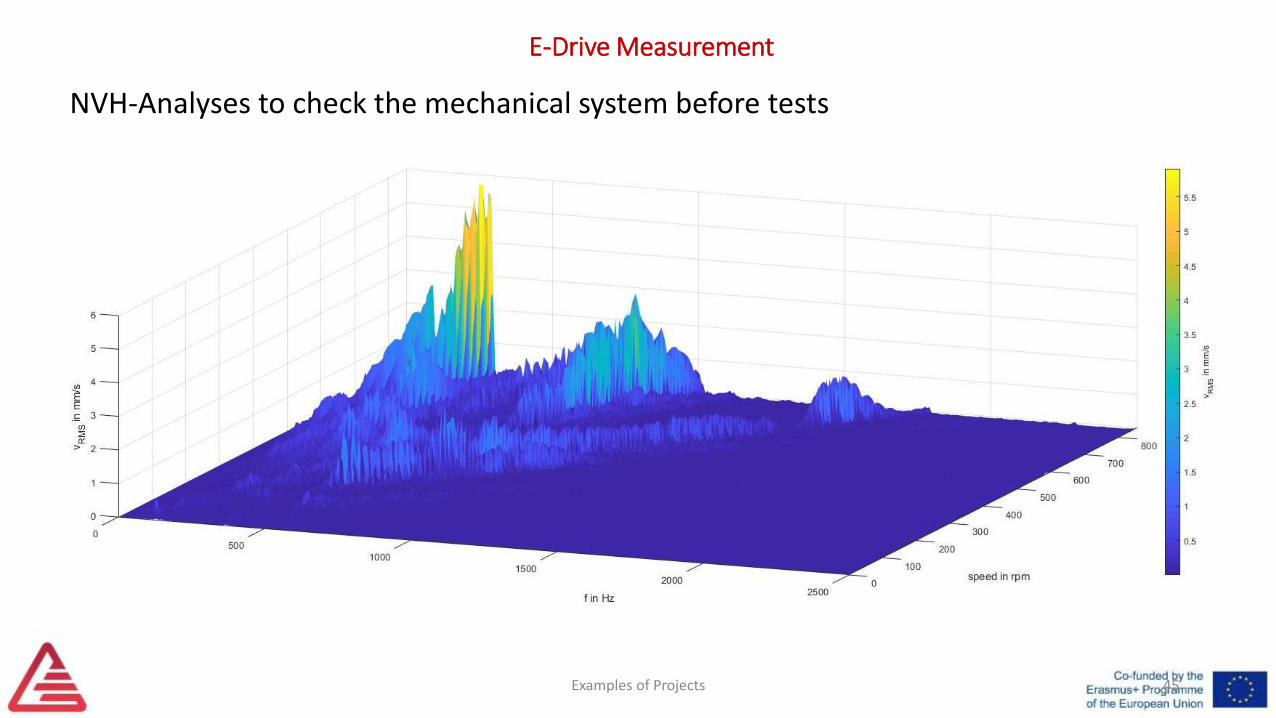
E-Drive Measurement
NVH-Analyses to check the mechanical system before tests

References• [1] Wiedner, Christoph: THE CHALLENGES OF ANALYZING THE
EFFICIENCY OF ELECTRICAL POWER TRAINS. DEWETRON GmbH, 2018
Examples of Projects 46

3. Educational-based Projects
Examples of Projects 47

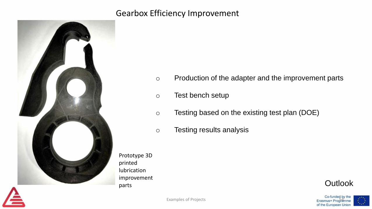
Gearbox Efficiency Improvement
Examples of Projects 48
Gearbox Efficiency Improvement
Task description
Examples of Projects 49
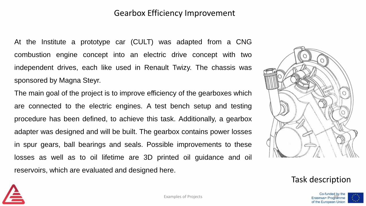
At the Institute a prototype car (CULT) was adapted from a CNG
combustion engine concept into an electric drive concept with two
independent drives, each like used in Renault Twizy. The chassis was
sponsored by Magna Steyr.
The main goal of the project is to improve efficiency of the gearboxes which
are connected to the electric engines. A test bench setup and testing
procedure has been defined, to achieve this task. Additionally, a gearbox
adapter was designed and will be built. The gearbox contains power losses
in spur gears, ball bearings and seals. Possible improvements to these
losses as well as to oil lifetime are 3D printed oil guidance and oil
reservoirs, which are evaluated and designed here.
Gearbox Efficiency Improvement
Losses
Examples of Projects 50
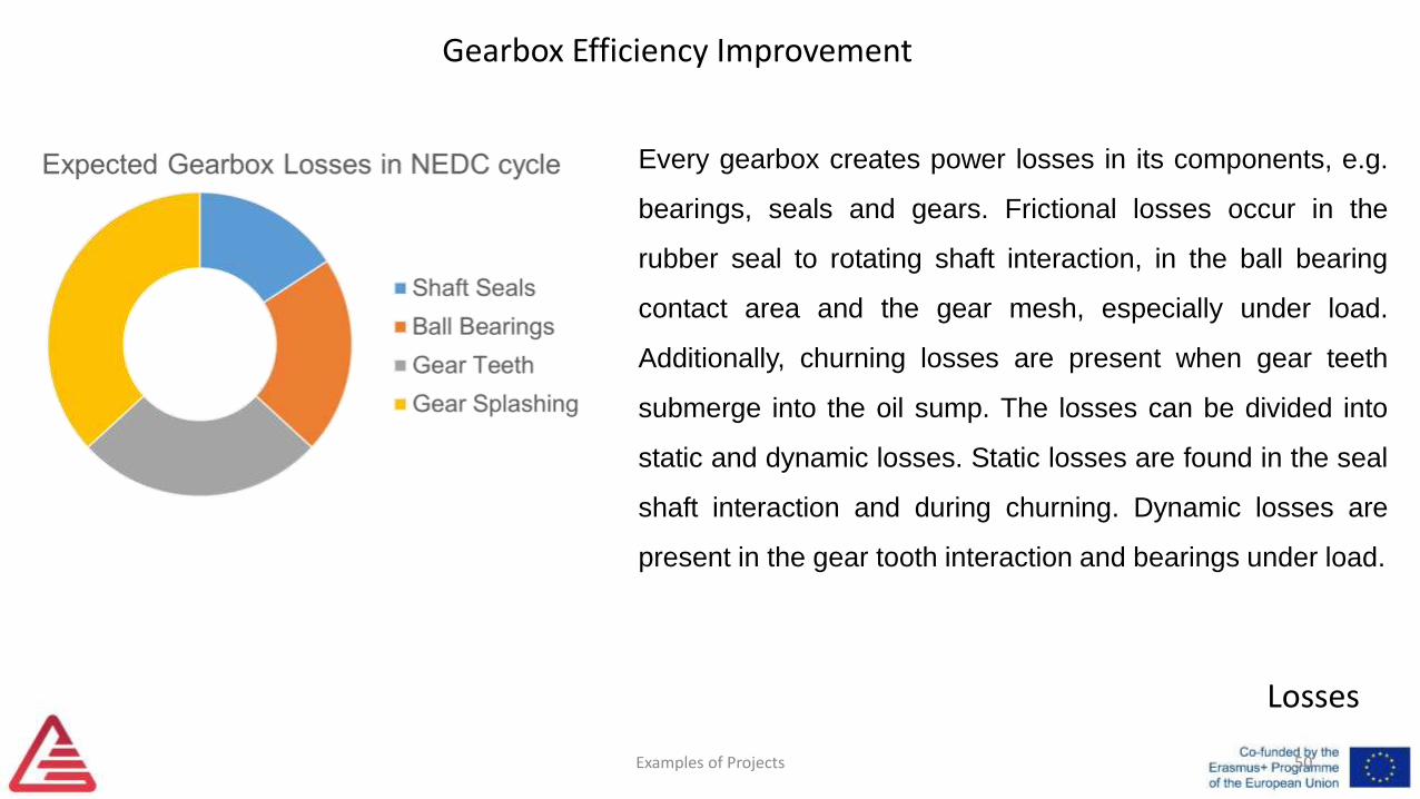
Every gearbox creates power losses in its components, e.g.
bearings, seals and gears. Frictional losses occur in the
rubber seal to rotating shaft interaction, in the ball bearing
contact area and the gear mesh, especially under load.
Additionally, churning losses are present when gear teeth
submerge into the oil sump. The losses can be divided into
static and dynamic losses. Static losses are found in the seal
shaft interaction and during churning. Dynamic losses are
present in the gear tooth interaction and bearings under load.
Gearbox Efficiency Improvement
Examples of Projects 51
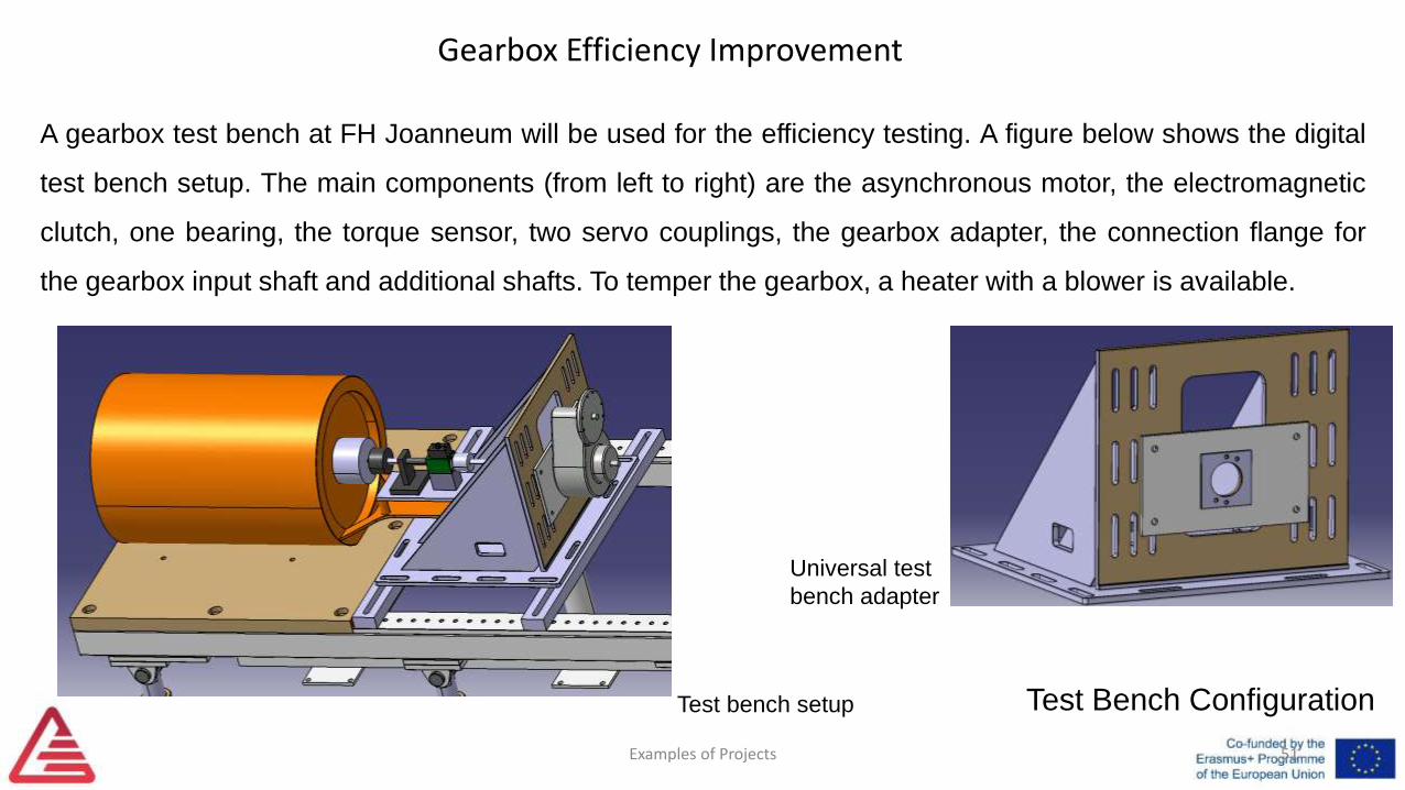
A gearbox test bench at FH Joanneum will be used for the efficiency testing. A figure below shows the digital
test bench setup. The main components (from left to right) are the asynchronous motor, the electromagnetic
clutch, one bearing, the torque sensor, two servo couplings, the gearbox adapter, the connection flange for
the gearbox input shaft and additional shafts. To temper the gearbox, a heater with a blower is available.
Test Bench ConfigurationTest bench setup
Universal test
bench adapter
Gearbox Efficiency Improvement
Examples of Projects 52
Testing Procedure
To minimize the test runs, a DoE was developed as a test plan. With the DoE it is possible to find
the best input parameter setting for the optimum output with minimum effort. It was possible to
reduce the amount of possible tests down to one third.
The main function of the adapter is to ensure the correct mounting position of the gearbox on the
test bench. Some important requirements for the adapter are: variable mounting orientations of the
gearbox on the adapter without sacrificing its functionality, high rigidity, and simple assembly and
production. To fix the gearbox on the adapter a Comex gearbox specific adapter plate is used as
can be seen above.
Gearbox Efficiency Improvement
Examples of Projects 53Design Process
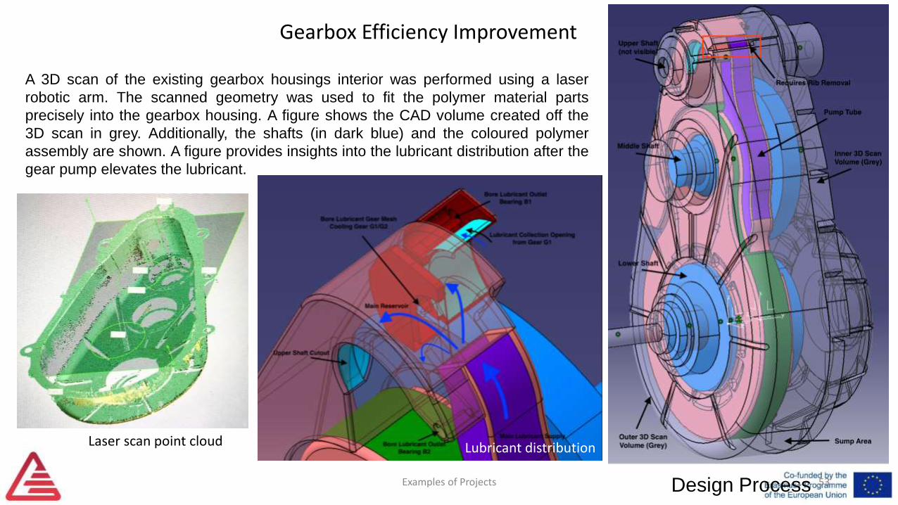
A 3D scan of the existing gearbox housings interior was performed using a laser
robotic arm. The scanned geometry was used to fit the polymer material parts
precisely into the gearbox housing. A figure shows the CAD volume created off the
3D scan in grey. Additionally, the shafts (in dark blue) and the coloured polymer
assembly are shown. A figure provides insights into the lubricant distribution after the
gear pump elevates the lubricant.
Laser scan point cloud Lubricant distribution
Gearbox Efficiency Improvement
Examples of Projects 54
Outlook
o Production of the adapter and the improvement parts
o Test bench setup
o Testing based on the existing test plan (DOE)
o Testing results analysis
Prototype 3D printed lubrication improvement parts

Formula Student
Examples of Projects 55

Formula Student
Examples of Projects 56

Formula Student
Conceiving and designing
Examples of Projects 57
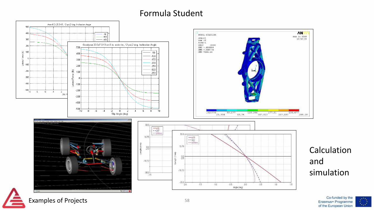
Calculation and simulation
Formula Student
Examples of Projects 58
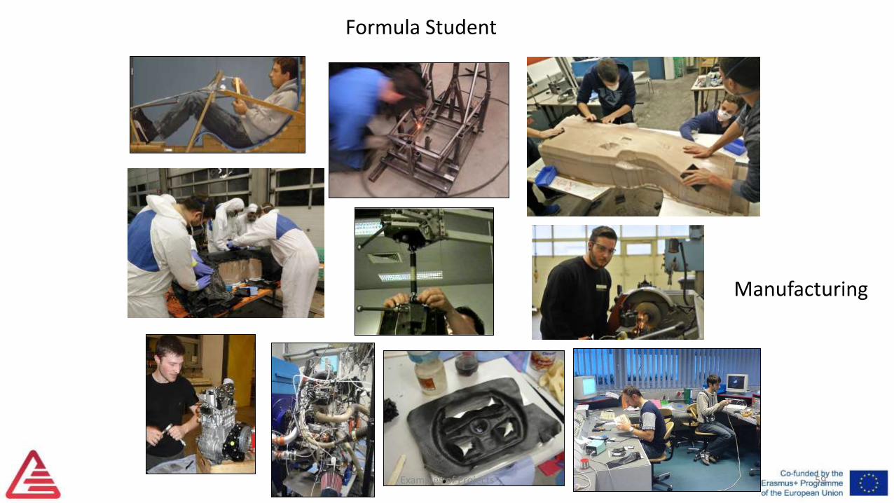
Formula Student
Manufacturing
Examples of Projects 59
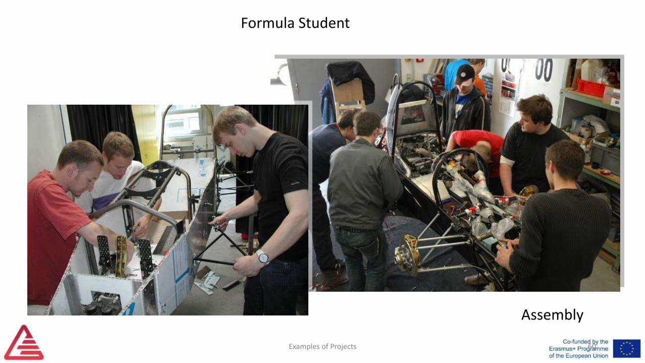
Formula Student
Assembly
Examples of Projects 60
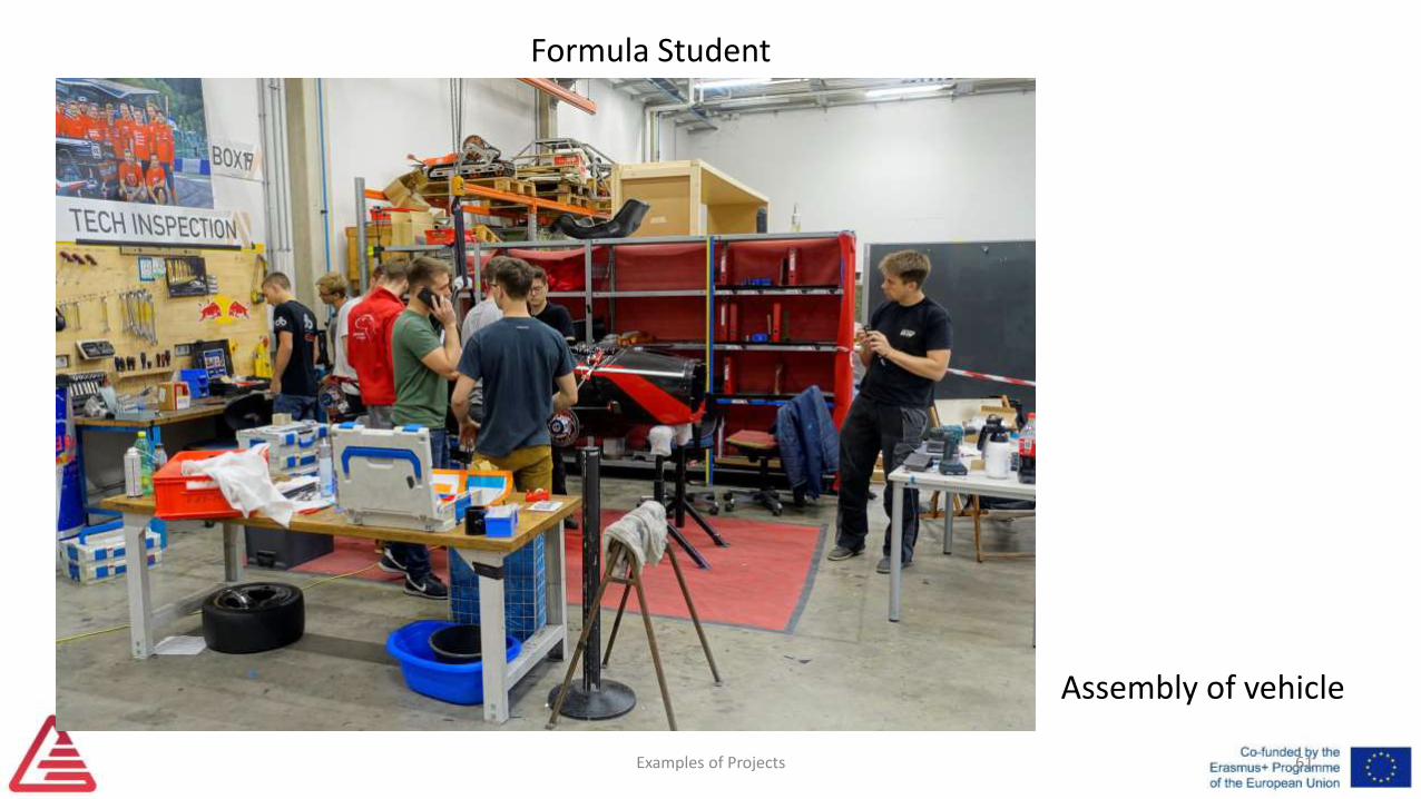
Assembly of vehicle
Formula Student
61Examples of Projects

Examples of Projects
Formula Student
Testing and development
62
Examples of Projects
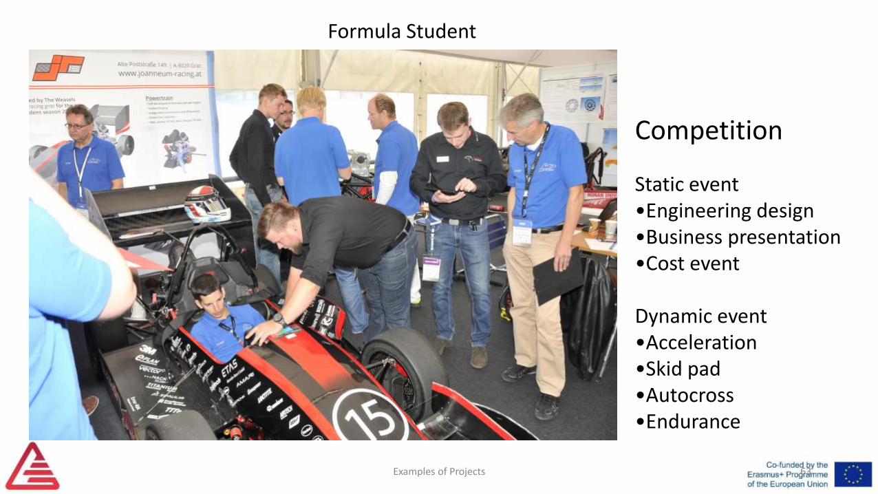
Formula Student
Competition
Static event•Engineering design•Business presentation•Cost event
Dynamic event•Acceleration•Skid pad•Autocross•Endurance
63
Examples of Projects
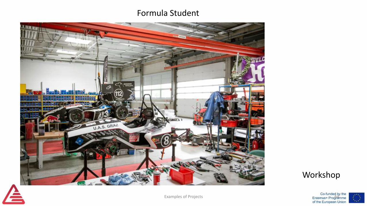
Formula Student
Workshop
64
Examples of Projects
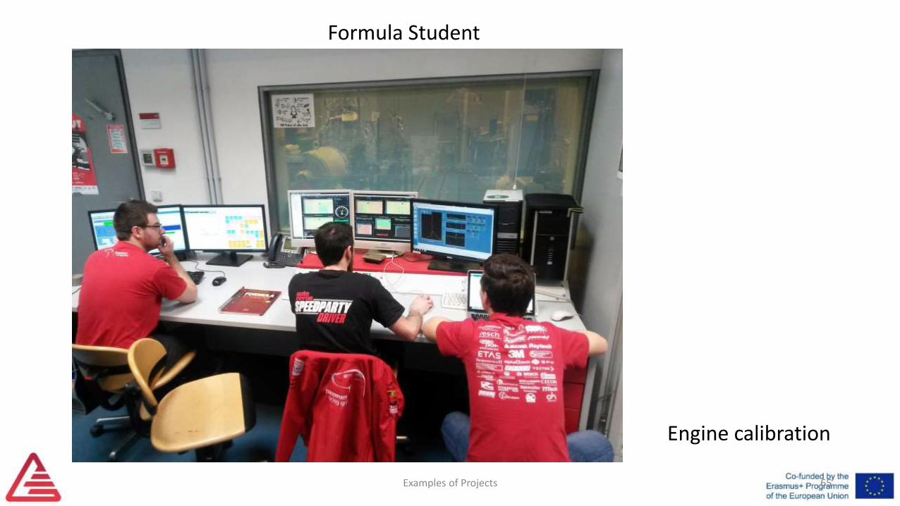
Formula Student
Engine calibration
65

Examples of Projects
Formula Student
Preparation for static competition with lecturers
66

Examples of Projects
Formula Student
Conceptual discussions with alumni
67

Examples of Projects
Formula Student
• Bachelor theses
• Master theses
• Design exercises: Bachelor’s, Master’s
• Project Work
• English Foundation: Poster presentation of sub projects and internships
68
Integration in curriculum:

Examples of Projects
Formula Student
• International comparison• Part of a prospering community• Development of entire(!) vehicle• Areas of interest of vehicle engineer:
• Design• Calculation/simulation• Manufacturing(assembly/quality assurance• Testing• Reporting and presenting• Sales and distribution• R&D
• Interdisciplinary activities• Team work, dead lines, costs entrance card to job• Contacts to industry, risk-free career entry
69
Advantages for students and faculty:
Drivetrain Efficiency
Examples of Projects 71
Drivetrain Efficiency
Examples of Projects 72
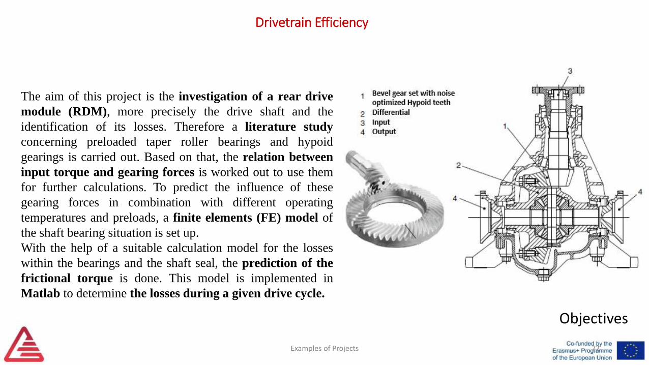
The aim of this project is the investigation of a rear drive
module (RDM), more precisely the drive shaft and the
identification of its losses. Therefore a literature study
concerning preloaded taper roller bearings and hypoid
gearings is carried out. Based on that, the relation between
input torque and gearing forces is worked out to use them
for further calculations. To predict the influence of these
gearing forces in combination with different operating
temperatures and preloads, a finite elements (FE) model of
the shaft bearing situation is set up.
With the help of a suitable calculation model for the losses
within the bearings and the shaft seal, the prediction of the
frictional torque is done. This model is implemented in
Matlab to determine the losses during a given drive cycle.
Objectives
Drivetrain Efficiency
Examples of Projects 73
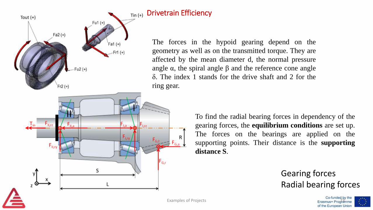
Gearing forcesRadial bearing forces
To find the radial bearing forces in dependency of the
gearing forces, the equilibrium conditions are set up.
The forces on the bearings are applied on the
supporting points. Their distance is the supporting
distance S.
The forces in the hypoid gearing depend on the
geometry as well as on the transmitted torque. They are
affected by the mean diameter d, the normal pressure
angle α, the spiral angle β and the reference cone angle
δ. The index 1 stands for the drive shaft and 2 for the
ring gear.
Drivetrain Efficiency
Examples of Projects 74
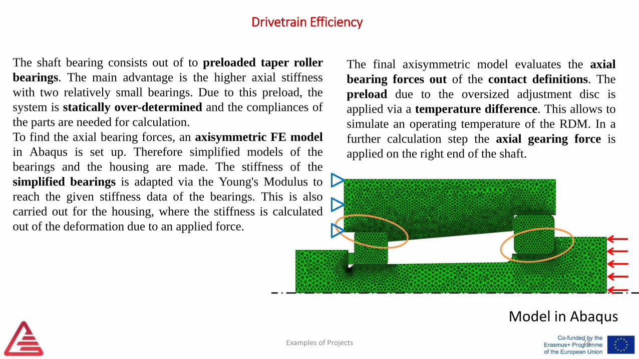
Model in Abaqus
The shaft bearing consists out of to preloaded taper roller
bearings. The main advantage is the higher axial stiffness
with two relatively small bearings. Due to this preload, the
system is statically over-determined and the compliances of
the parts are needed for calculation.
To find the axial bearing forces, an axisymmetric FE model
in Abaqus is set up. Therefore simplified models of the
bearings and the housing are made. The stiffness of the
simplified bearings is adapted via the Young's Modulus to
reach the given stiffness data of the bearings. This is also
carried out for the housing, where the stiffness is calculated
out of the deformation due to an applied force.
The final axisymmetric model evaluates the axial
bearing forces out of the contact definitions. The
preload due to the oversized adjustment disc is
applied via a temperature difference. This allows to
simulate an operating temperature of the RDM. In a
further calculation step the axial gearing force is
applied on the right end of the shaft.
Drivetrain Efficiency
Examples of Projects 75
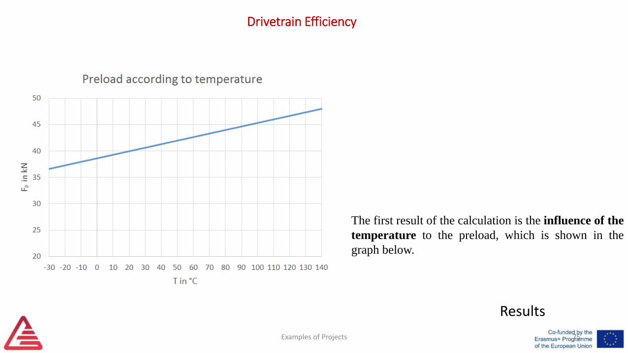
Results
The first result of the calculation is the influence of the
temperature to the preload, which is shown in the
graph below.
Drivetrain Efficiency
Examples of Projects 76
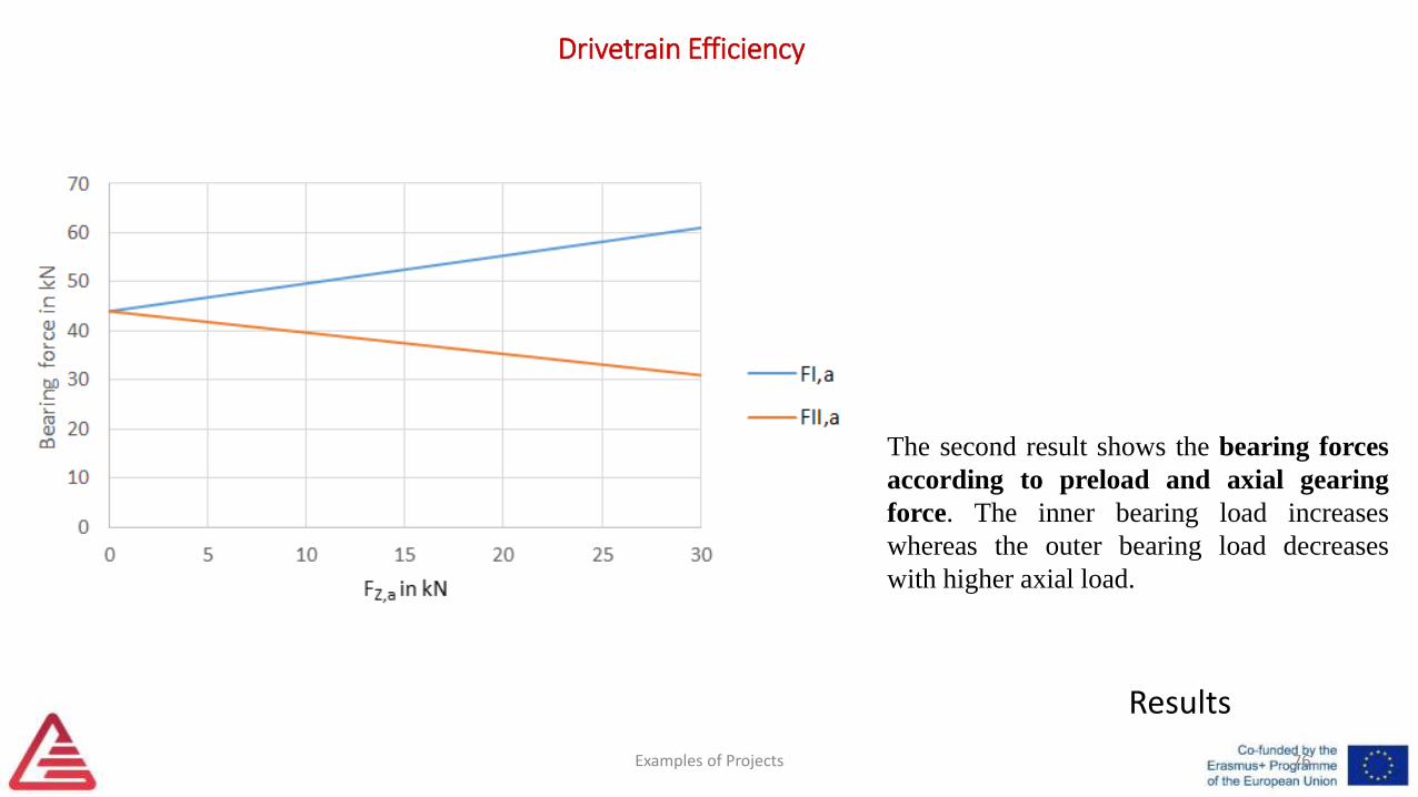
Results
The second result shows the bearing forces
according to preload and axial gearing
force. The inner bearing load increases
whereas the outer bearing load decreases
with higher axial load.
Drivetrain Efficiency
Examples of Projects 77
Frictional torque
To calculate the losses in the bearings of the drive shaft, it is
necessary to find a relation between the loads on the bearings
and the frictional torque. The bearings in the investigated
rear drive module are therefore investigated in terms of their
behaviour concerning loads in radial direction and in axial
direction.
The total frictional torque created in bearings is made up by
four parts: Rolling, sliding and seal friction in the bearing
and the torque due to the displacement and churning of the
lubricant.
Drivetrain Efficiency
Examples of Projects 78
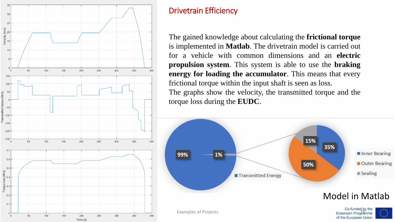
Model in Matlab
The gained knowledge about calculating the frictional torque
is implemented in Matlab. The drivetrain model is carried out
for a vehicle with common dimensions and an electric
propulsion system. This system is able to use the braking
energy for loading the accumulator. This means that every
frictional torque within the input shaft is seen as loss.
The graphs show the velocity, the transmitted torque and the
torque loss during the EUDC.
References• • Reisinger K. et al.: Endbericht Innovationsscheck Plus 2017, FH
Joanneum – AMSD, Mar. 2019. (Final report of cooperation project)
Examples of Projects 79

Examples of Projects4th Training in Rio de Janeiro, BRA
6th-9th of May 2019Michael Trzesniowski, Thomas Lechner
"The European Commission support for the production of this publication does not constitute an endorsement of the contents which reflects the views only of the authors, and the Commission cannot be held responsible for any use which may be made of the information contained therein.“
FOR EDUCATIONAL PURPOSE ONLY