Embed Size (px)
Citation preview

Rock WeirEL 256.5STA 3+32
Rock WeirEL 255.7STA 3+77
Rock WeirEL 254.8
STA 4+22
Rock RibSTA 3+63 Rock Rib
STA 3+98
End of FootingSTA 3+34.5
End of FootingSTA 4+13.4
>>
>> > > > > > > > > > > > > > > > > > >
>
> >
4+00
DRAWINGTITLE
PROJECT NAME
DRAWN
DESIGNER
CHECKED
ARCHIVE NO.
DATE
PROJECT NO.
DWG SHEET NO.
OFSHEET
United States Department of AgricultureForest Service
3/8/19
16:1
5 BRE
NDAN
F:\6
904 U
SFS
- TON
GASS
NF
AOP
SITE
S (1
4)\D
WG\
6904
-RD2
0500
00-M
P22.2
3-DE
SIGN
-FIL
L W
ARPI
NG.D
WG;
REGION 10ALASKAN REGION
ROCK WEIR DETAILS
Mar-19
M. JENSEN
B. MCCRAY
M. JENSEN
6904
129
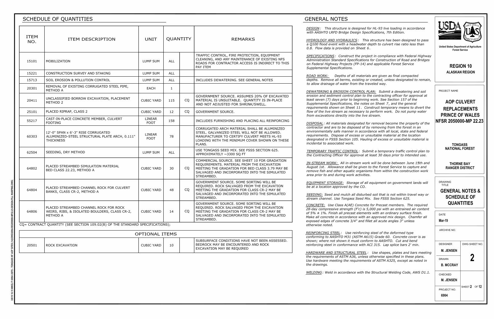
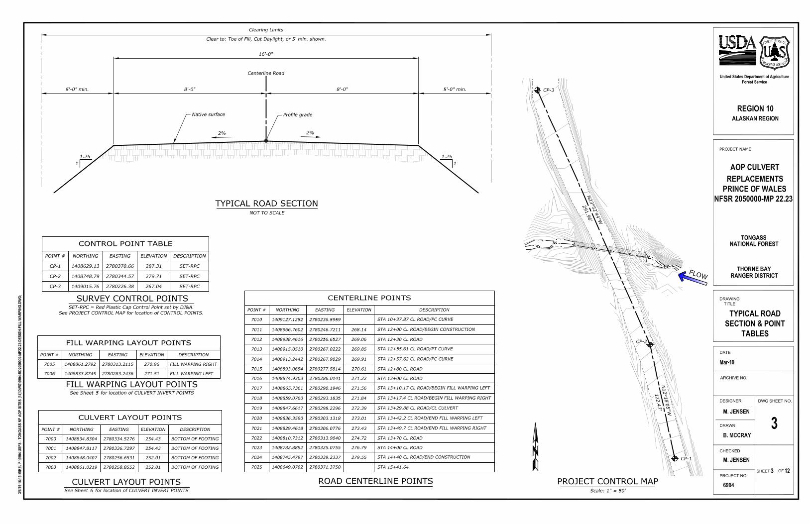
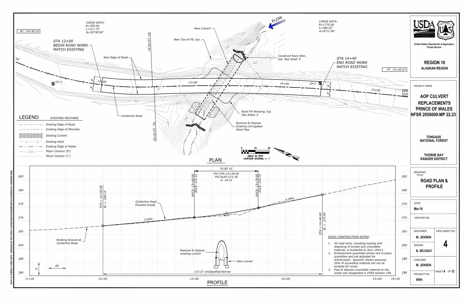
AOP CULVERT
TONGASS
THORNE BAY
REPLACEMENTSPRINCE OF WALES
RANGER DISTRICT
NATIONAL FOREST
NFSR 2050000-MP 22.23
9
FLOW
FLOW
Surface rock.
Surface and Footer Rocksto be 24"-30" dia.(Channel Rock Class CR-2 )
FLOW RiffleLength Varies
Pool Length
Varies 6' to 8'
0.9%
Streambed gradebetween weirs
19
ROCK WEIR PROFILENOT TO SCALE
Step Height Varies: 5" to 7"
Footer Rock,typ.
Key in rock weir to streambank for rock weirs outside ofculvert, see DETAIL this sheet.
110
310
Place and embed IsolatedBoulder, Class CR-2. Seesheet 10 for layout locations
Construct Rock Weirs from ClassCR-2 Channel Rock, typ.See DETAIL on this sheet for rockweir details outside of culvert
ROCK WEIR PLANNOT TO SCALE
Streambed Simulation Rock,Bed Class 22.23 betweenrock weirs. See sheet 10
Slight contraction tobankfull width justupstream of rock weir.
Construct continuoushardened banks theentire length of theculvert with ClassCR-2 Channel Rock
Stream Thalweg
Construct Rock Ribfrom Class CR-2Channel Rock, typ. Seenotes on this sheet.
Edge of Bank, typ. Varybankfull width along length ofriffle. See TYPICAL RIFFLESECTION on Sheet 10
Footing Stem Wall
19
410
230°
Surface Rock,typ.
103
(3) Rock Weirs @ ±45' C-C Typical Spacing 30°typ.
Existing groundalong new streamthalweg
New culvert
Streambed SimulationRock, Bed Class 22.23between rock weirs.See sheet 10
STREAM PROFILENOT TO SCALE
(3) Rock Weirs
ROCK WEIR PLAN - OUTSIDE CULVERTNot to Scale
FLO
W
W
W/3 W/3 W/3
Apex
60° max.60° max.
Backfill with nativestreambed material flushwith top of surface rocks.
Layout PT.location
Bank
FLOW
10"±
New streambed
Footer Rock.Excavate and place belowstreambed as shown
Rock Weir Layout PT. Location(top of rock)
SECTION A-ANot to Scale
Provide gaps inSurface Rocks in themiddle 13 of thechannel
Surface and Rocks to be24"-30" dia.(Channel Rock Class CR-2 )
4'-0"±
Key rocks intobank
Place Surface Rocks andFooter Rocks as close togetheras possible so that gapsbetween any of the rocks areminimized, except as noted.
A
A
3+20
3+40 3+60
3+80
4+40
4+20
Pool Depth Varies: 8" to 12"
Channel Rock Bank outside ofstructure. Cover with slash fromclearing and grubbing and unsuitablematerial conserved from excavation.Place seeding on channel banks.Typical of both sides.
STA 4+34Transition Channel Rockbanks and StreambedSimulation Rock intoexisting steam.
STA 4+34End Channel Rock banks andStreambed Simulation Rock.Transition into existing steam.
STA 3+21Begin Channel Rock banks andStreambed Simulation Rock. Tie intoexisting steambed and banks.
STA 3+21Begin Channel Rockbanks and StreambedSimulation Rock. Tieinto existing steambedand banks.
±45' Rock Weir spacing ±45' Rock Weir spacing
±35' Rock Rib Spacing
2
Rib rock will be in contact with the adjacent piece and protrude ±3" fromstream bed.
1
2
ROCK WEIR & RIB NOTES
Vary direction, shape, and orientation of the ribs. Ribs to be angled30°± perpendicular to centerline of pipe. Ribs oriented straight acrossthe channel are not desirable
3 Rock Weir & Rib placement is 1'± from designated station shown in profile. Thespacing and configuration of rock weirs maybe adjusted in the field by the COto fit actual streambed conditions.
3
3
3
3
3
Footer rockto control scour.
210
19
POOL
RIFFLE
DRAWINGTITLE
PROJECT NAME
DRAWN
DESIGNER
CHECKED
ARCHIVE NO.
DATE
PROJECT NO.
DWG SHEET NO.
OFSHEET
United States Department of AgricultureForest Service
3/8/19
16:1
5 BRE
NDAN
F:\6
904 U
SFS
- TON
GASS
NF
AOP
SITE
S (1
4)\D
WG\
6904
-RD2
0500
00-M
P22.2
3-DE
SIGN
-FIL
L W
ARPI
NG.D
WG;
REGION 10ALASKAN REGION
STREAM SIMULATIONDETAILS
Mar-19
M. JENSEN
B. MCCRAY
M. JENSEN
6904
1210
AOP CULVERT
TONGASS
THORNE BAY
REPLACEMENTSPRINCE OF WALES
RANGER DISTRICT
NATIONAL FOREST
NFSR 2050000-MP 22.23
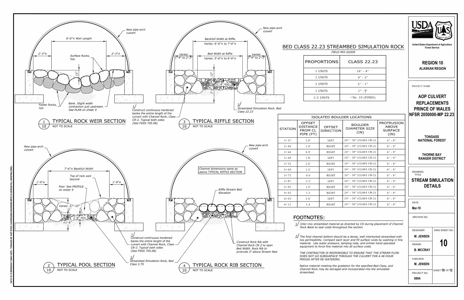
10Construct continuous hardenedbanks the entire length of theculvert with Channel Rock, ClassCR-2. Typical both sides(See FSSS 705.08)
Streambed Simulation Rock, BedClass 3.79
2
1
210
TYPICAL POOL SECTIONNOT TO SCALE
310
TYPICAL RIFFLE SECTIONNOT TO SCALE
7'-6"± Bankfull Width
1'-9"± 1'-9"±
Bankfull Width at RiffleVaries: 6'-6"± to 7'-6"±
110
TYPICAL ROCK WEIR SECTIONNOT TO SCALE
6'-6"± Weir Length
12"
Surface Rocks,typ.
Footer Rocks,typ.
Bank. Slight widthcontraction just upstream.See PLAN on sheet 9
New pipe-archculvert
Top of rock weirbeyond
Pool- See PROFILEon sheet 9
New pipe-archculvert
New pipe-archculvert
Streambed Simulation Rock, BedClass 22.23
2
PROPORTIONS CLASS 22.23
1 UNITS 16" - 4"
2 UNITS 4" - 2"
2 UNITS 2" - 1"
1 UNITS 1" - 12"
1/2 UNITS <No. 10 (FINES)
BED CLASS 22.23 STREAMBED SIMULATION ROCKFIELD MIX GUIDE
Construct continuous hardenedbanks the entire length of theculvert with Channel Rock, ClassCR-2. Typical both sides(See FSSS 705.08)
1
New pipe-archculvert
410
TYPICAL ROCK RIB SECTIONNOT TO SCALE
Construct Rock Rib withChannel Rock CR-2 to spanBed Width. Rock Rib toprotrude 3" above Stream Bed
Riffle Stream BedElevation
Channel dimensions same asabove TYPICAL RIFFLE SECTION
Bed Width at RiffleVaries: 5'-6"± to 6'-6"±
2'-3"± 2'-3"± Varies:1'-9" to 2'-3"
Varies:1'-9" to 2'-3"
Varies: 27"-33"
12"
3'-
0"
±1'-6" Inter-mix streambed material as directed by CO during placement of ChannelRock Bank to seal voids throughout the section.
FOOTNOTES:1
2
FOOTNOTES:
The final channel bottom should be a dense, well interlocked streambed withlow permeability. Compact each layer and fill surface voids by washing in finematerial. Use water pressure, tamping rods, and similar hand operatedequipment to force fine material into all surface voids.
THE CONTRACTOR IS RESPONSIBLE TO ENSURE THAT THE STREAM FLOWDOES NOT GO SUBSURFACE THROUGH THE CULVERT FOR A 48 HOURPERIOD AFTER RE-WATERING.
Native material meeting the gradation for the specified Bed Class, andChannel Rock may be salvaged and incorporated into the simulatedstreambed.
1'-6" min.
1'-6" min.
ISOLATED BOULDER LOCATIONS
STATION
OFFSETDISTANCEFROM CLPIPE (FT)
OFFSETDIRECTION
BOULDERDIAMETER SIZE
(IN)
PROTRUSIONABOVE
SURFACE(IN)
3+37 2.8' LEFT 24" - 30" (CLASS CR-2) 6" - 9"
3+40 1.9' RIGHT 24" - 30" (CLASS CR-2) 6" - 9"
3+44 0.9' RIGHT 24" - 30" (CLASS CR-2) 6" - 9"
3+49 1.8' LEFT 24" - 30" (CLASS CR-2) 6" - 9"
3+55 2.6' RIGHT 24" - 30" (CLASS CR-2) 6" - 9"
3+69 1.2' LEFT 24" - 30" (CLASS CR-2) 6" - 9"
3+73 0.6 RIGHT 24" - 30" (CLASS CR-2) 6" - 9"
3+87 2.3' LEFT 24" - 30" (CLASS CR-2) 6" - 9"
3+95 1.9' RIGHT 24" - 30" (CLASS CR-2) 6" - 9"
4+02 1.5 RIGHT 24" - 30" (CLASS CR-2) 6" - 9"
4+03 2.6' LEFT 24" - 30" (CLASS CR-2) 6" - 9"
4+11 1.4 RIGHT 24" - 30" (CLASS CR-2) 6" - 9"
DRAWINGTITLE
PROJECT NAME
DRAWN
DESIGNER
CHECKED
ARCHIVE NO.
DATE
PROJECT NO.
DWG SHEET NO.
OFSHEET
United States Department of AgricultureForest Service
3/8/19
16:1
5 BRE
NDAN
F:\6
904 U
SFS
- TON
GASS
NF
AOP
SITE
S (1
4)\D
WG\
6904
-RD2
0500
00-M
P22.2
3-DE
SIGN
-FIL
L W
ARPI
NG.D
WG;
REGION 10ALASKAN REGION
DEWATERINGREQUIREMENTS
Mar-19
M. JENSEN
B. MCCRAY
M. JENSEN
6904
1211
AOP CULVERT
TONGASS
THORNE BAY
REPLACEMENTSPRINCE OF WALES
RANGER DISTRICT
NATIONAL FOREST
NFSR 2050000-MP 22.23
11
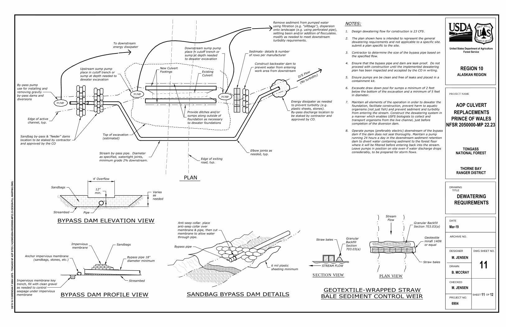
BYPASS DAM PROFILE VIEW
Impervious membrane keytrench, fill with clean gravelas needed to controlseepage under imperviousmembrane
Anchor impervious membrane(sandbags, stones, etc.)
Imperviousmembrane
Sandbags
Bypass pipe 18"diameter minimum
Streambed
ExistingCulvert
PUMP
PUMP
Top of excavation(estimated)
Remove sediment from pumped waterusing filtration (e.g. "siltbags"), dispersiononto landscape (e.g. using perforated pipe),settling basin and/or addition of flocculates.modify as needed to meet downstreamturbidity requirements.
To downstreamenergy dissipater
Sandbag by-pass & "feeder" damslocation to be staked by contractorand approved by the CO
By-pass pumpuse for installing andremoving gravityby-pass dams anddiversions
Construct backwater dam toprevent water from enteringwork area from downstream
D/S Flow
(No turbidity)
Energy dissipater as neededto prevent turbidity (e.g.plastic sheets, stones).By-pass discharge location tobe staked by contractor andapproved by CO.
PUMP
Stream by-pass pipe. Diameteras specified, watertight joints,minimum grade 2% downstream.
PLAN
Upstream sump pumpplace in cutoff trench orsump at depth needed todewater excavation
Sedimats- details & numberof rows per manufacturer
Elbow joints asneeded, typ.
Edge of exitingroad, typ.
Edge of activechannel, typ.
BYPASS DAM ELEVATION VIEW
4' Overflow
12"min. Varies
Sandbags
Streambed Pipe
asneeded
GEOTEXTILE-WRAPPED STRAWBALE SEDIMENT CONTROL WEIR
SECTION VIEW PLAN VIEW
STREAM FLOW
GranularBackfillSection703.03(a)
Straw bales
Granular BackfillSection 703.03(a)
Straw bales
Geotextilemirafi 140Nor equal
StreamFlow
SANDBAG BYPASS DAM DETAILS
Anti-seep collar. placeanti-seep collar overmembrane & pipe, then cutmembrane to allow waterthrough pipe.
6 mil plasticsheeting minimum
Bypass pipe
Downstream sump pumpplace in cutoff trench orsump at depth neededto dewater excavation
NOTES:1. Design dewatering flow for construction is 23 CFS.
2. The plan shown here is intended to represent the generaldewatering requirements and not applicable to a specific site.submit a plan specific to the site.
3. Contractor to determine the size of the bypass pipe based onthe specified flow.
4. Ensure that the bypass pipe and dam are leak-proof. Do notproceed with construction until the implemented dewateringplan has been inspected and accepted by the CO in writing.
5. Ensure pumps are be clean and free of leaks and placed in acontainment kit.
6. Excavate draw down pool for sumps a minimum of 2 feetbelow the bottom of the excavation and a minimum of 5 feetin diameter.
7. Maintain all elements of the operation in order to dewater thefoundation, facilitate construction, prevent harm to aquaticorganisms (not just fish) and prevent sediment and turbidityfrom entering the stream. Construct the dewatering system ina manner which enables USFS biologists to collect andtransport organisms from the live channel, just beforecompletion of the diversion dam.
8. Operate pumps (preferably electric) downstream of the bypassdam if the dam does not seal thoroughly. Maintain a pumprunning 24 hours a day in the downstream sediment retentiondam to divert water containing sediment to the forest floorwhere it will be filtered before entering back into the stream.Leave pumps in position on site even if water discharge dropsconsiderably, to be prepared for storm flows.
> > > > >
> > > > >
Provide ditches and/orsumps along outside offoundation as necessaryto dewater foundations
New CulvertFootings
DRAWINGTITLE
PROJECT NAME
DRAWN
DESIGNER
CHECKED
ARCHIVE NO.
DATE
PROJECT NO.
DWG SHEET NO.
OFSHEET
United States Department of AgricultureForest Service
3/8/19
16:1
5 BRE
NDAN
F:\6
904 U
SFS
- TON
GASS
NF
AOP
SITE
S (1
4)\D
WG\
6904
-RD2
0500
00-M
P22.2
3-DE
SIGN
-FIL
L W
ARPI
NG.D
WG;
REGION 10ALASKAN REGION
PRECAST FOOTINGDETAILS (OPTIONAL)
Mar-19
M. JENSEN
B. MCCRAY
M. JENSEN
6904
1212
AOP CULVERT
TONGASS
THORNE BAY
REPLACEMENTSPRINCE OF WALES
RANGER DISTRICT
NATIONAL FOREST
NFSR 2050000-MP 22.23
12
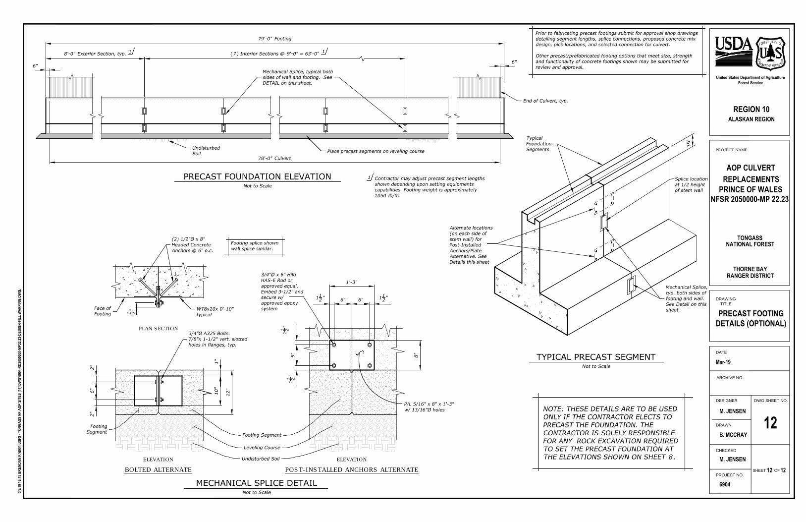
6"6"
78'-0" Culvert
79'-0" Footing
End of Culvert, typ.
Mechanical Splice, typical bothsides of wall and footing. SeeDETAIL on this sheet.
(7) Interior Sections @ 9'-0" = 63'-0"8'-0" Exterior Section, typ.
1 Contractor may adjust precast segment lengthsshown depending upon setting equipmentscapabilities. Footing weight is approximately1050 lb/ft.
11
Mechanical Splice,typ. both sides offooting and wall.See Detail on thissheet.
TypicalFoundationSegments
Splice locationat 1/2 heightof stem wall
Alternate locations(on each side ofstem wall) forPost-InstalledAnchors/PlateAlternative. SeeDetails this sheet
10"
Prior to fabricating precast footings submit for approval shop drawingsdetailing segment lengths, splice connections, proposed concrete mixdesign, pick locations, and selected connection for culvert.
Other precast/prefabricated footing options that meet size, strengthand functionality of concrete footings shown may be submitted forreview and approval.
PRECAST FOUNDATION ELEVATIONNot to Scale
TYPICAL PRECAST SEGMENTNot to Scale
UndisturbedSoil
NOTE: THESE DETAILS ARE TO BE USEDONLY IF THE CONTRACTOR ELECTS TOPRECAST THE FOUNDATION. THECONTRACTOR IS SOLELY RESPONSIBLEFOR ANY ROCK EXCAVATION REQUIREDTO SET THE PRECAST FOUNDATION ATTHE ELEVATIONS SHOWN ON SHEET 8.
1 2"
PLAN SECTION
ELEVATION
BOLTED ALTERNATE
Footing Segment
Undisturbed Soil
12"
10"
1"
2"
6"
2"
FootingSegment
3/4"Ø A325 Bolts.7/8"x 1-1/2" vert. slottedholes in flanges, typ.
Footing splice shownwall splice similar.
(2) 1/2"Ø x 8"Headed ConcreteAnchors @ 6" o.c.
WT8x20x 0'-10"typical
Face ofFooting
ELEVATION
POST-INSTALLED ANCHORS ALTERNATE
1'-3"
6"112" 6" 11
2"
8"
5"
11 2"
11 2"
P/L 5/16" x 8" x 1'-3"w/ 13/16"Ø holes
3/4"Ø x 6" HiltiHAS-E Rod orapproved equal.Embed 3-1/2" andsecure w/approved epoxysystem
MECHANICAL SPLICE DETAILNot to Scale
Leveling Course
Place precast segments on leveling course