Embed Size (px)
Citation preview

Knowledge Base Article
Example Access Control Project
Involving Elevators
Copyright © 2008-2013, ISONAS Security Systems
All rights reserved
Table of Contents
1: INTRODUCTION ...................................................................................................................................... 3 1.1: PROBLEM DESCRIPTION: ............................................................................................................. 3 1.2: DIGITAL I/O CONCEPTS: ............................................................................................................... 4
2: ELEVATOR CONTROL ........................................................................................................................... 5 2.1: INITIAL INSTALLATION CONFIGURATION ............................................................................... 6
2.1.1: I/O MODULE CONFIGURATION ............................................................................................. 6 2.1.2: I/O GROUP CONFIGURATION ................................................................................................ 8 2.1.3: DOOR CONFIGURATION ......................................................................................................... 8 2.1.4: I/O PROFILE CONFIGURATION .............................................................................................. 9 2.1.5: DOOR GROUP CONFIGURATION ......................................................................................... 10 2.1.6: PERMISSION CONFIGURATION ........................................................................................... 11 2.1.7: SOLUTION SUMMARY........................................................................................................... 11
2.2: SUPPORTING MORE GENERAL USE OF THE ELEVATOR (CHANGE ORDER #1 ) ........... 12 2.2.1: CHANGE DESCRIPTION......................................................................................................... 12 2.2.2: SHIFT CONFIGURATION ....................................................................................................... 12 2.2.2: I/O PROFILE CONFIGURATION ............................................................................................ 12 2.2.3: I/O BUSINESS RULE CONFIGURATION .............................................................................. 13 2.2.4: STANDALONE OPERATION MODIFICATION .................................................................... 13 2.2.5: SOLUTION SUMMARY........................................................................................................... 13
2.3: CONTROLLING PUBLIC ACCESS TO CERTAIN FLOORS (CHANGE ORDER #2 ) ............. 14 2.3.1: CHANGE DESCRIPTION......................................................................................................... 14 2.3.2: I/O PROFILE CONFIGURATION ............................................................................................ 14 2.3.3: OVERRIDE CARD .................................................................................................................... 15
3: COMMUNICATIONS TO/FROM THE ELEVATOR CAR .................................................................. 16 4: EXAMPLE MODBUS/TCP MODULE SETTINGS ............................................................................... 17
4.1: ADAM 6060 ..................................................................................................................................... 17 4.2: SEALEVEL 410E ............................................................................................................................ 19
Document Version
( KBA0110ElevatorDigitalIO.Doc )
Date of Revision Revision Author Description
11/10/2008 1.0 Shirl Jones Initial Release
10/25/2013 1.1 Shirl Jones Updated to reflect current version of Crystal
Matrix
Added IOModule config examples
Elevators & Digital I/O 3
1: INTRODUCTION This document describes an advanced installation, in which the Digital I/O features of the Crystal Matrix software are used.
By reviewing the example configurations, you should gain an understanding of the
different ways you can set up the ISONAS system to meet your customer’s requirements.
It is assumed that you are already comfortable and familiar with configuring the basic Who/When/Where concepts within the Crystal Matrix Software.
This paper focuses on an elevator installation, but the same techniques could be
used to control lights, cabinets, or basic building alarms.
1.1: PROBLEM DESCRIPTION:
The Tropical High School (THS) is installing the ISONAS Access Control System. The facility is a five (5) story building, with an elevator, and multiple exterior and
interior doors being controlled by the ISONAS Access Control System.
The part of the project that this document discusses includes:
Initial Installation Requirements
Configure the system so that an access card is required to use the elevator. Card holders assigned to the “Staff” and “Maintenance”
groups will be allowed access to the elevator. The floors serviced by the elevator are Basement, Ground, 2nd, 3rd , and 4th Floors. Access to
the Ground Floor will always be allowed, and will not be controlled by the access control system.
Change Order #1 Requirements After the system is used for a while, it is determined that the elevator
should be open for general use between 08:00 – 17:00 Monday – Friday. Access Cards are only required during “off hours”.
Change Order #2 Requirements
Add a restriction to the elevator so that: Access to the Basement and the 4rd floors always requires the
use of an access card.
Access to the 2nd and 3rd Floors is: Open for general use between 08:00 – 17:00,
Monday – Friday. “Off hours” access requires the use of an access card.
As we will see, the Digital I/O features of the ISONAS system will be used to support
the elevator.
Elevators & Digital I/O 4
1.2: DIGITAL I/O CONCEPTS:
When using the Digital I/O features of the Crystal Matrix software package, there are a few concepts that should be understood.
Terms Used:
IO Module --- A piece of hardware, which contains input and/or output
points. The output points are typically relay contacts. The software supports having 32 input and output points on a single IO Module.
An IO Module allows certain characteristics of the points to be defined. Examples include: 1) A point may create alarms or history records. 2) A
point can be named.
The Communications between the Host computer and the IO Module uses the Modbus/TCP protocol, which is an industrial automation protocol.
IO Supervisor --- An ISONAS program that runs on the host
computer, and handles the data communications with one or more IO Modules.
IO Group --- IO Groups allow the Crystal Matrix software to easily handle
customer requirements where more than 32 points are needed to support an
elevator. An IO Group consists of one or more IO Modules. When configuring the Crystal Software’s rules that control the IO points, IO Groups are used.
When working with Elevators, an IO Group represents a physical elevator
IO Profile --- IO Profiles define how the points in an IOGroup are
handled.
An IOProfile of “AllFloors” might activate all the output points for 2 seconds.
An IOProfile of “Public” might activate 2 output points, allowing the system to
enable access to just those two floors.
When working with Elevators, the IO Profile represents a set of floors that are available to the people associated with that IO Profile.
Elevators & Digital I/O 5
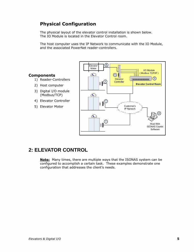
Physical Configuration
The physical layout of the elevator control installation is shown below. The IO Module is located in the Elevator Control room.
The host computer uses the IP Network to communicate with the IO Module,
and the associated PowerNet reader-controllers.
Components 1) Reader-Controllers
2) Host computer
3) Digital I/O module
(Modbus/TCP)
4) Elevator Controller
5) Elevator Motor
2: ELEVATOR CONTROL
Note: Many times, there are multiple ways that the ISONAS system can be configured to accomplish a certain task. These examples demonstrate one
configuration that addresses the client’s needs.
Elevators & Digital I/O 6
2.1: INITIAL INSTALLATION CONFIGURATION
2.1.1: I/O MODULE CONFIGURATION
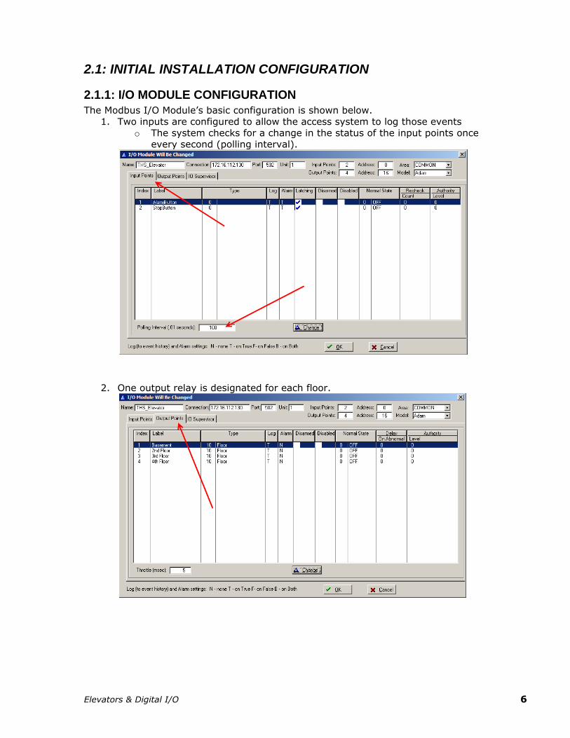
The Modbus I/O Module’s basic configuration is shown below.
1. Two inputs are configured to allow the access system to log those events
o The system checks for a change in the status of the input points once every second (polling interval).
2. One output relay is designated for each floor.
Elevators & Digital I/O 7
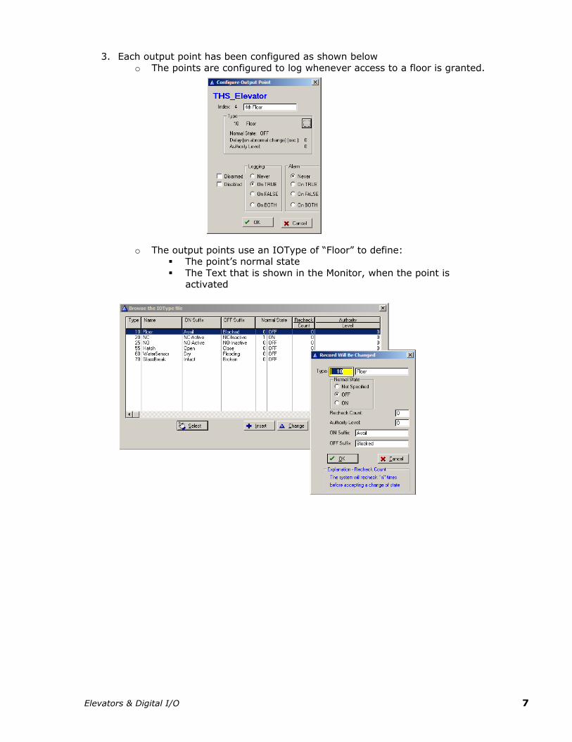
3. Each output point has been configured as shown below
o The points are configured to log whenever access to a floor is granted.
o The output points use an IOType of “Floor” to define:
The point’s normal state
The Text that is shown in the Monitor, when the point is activated
Elevators & Digital I/O 8
2.1.2: I/O GROUP CONFIGURATION
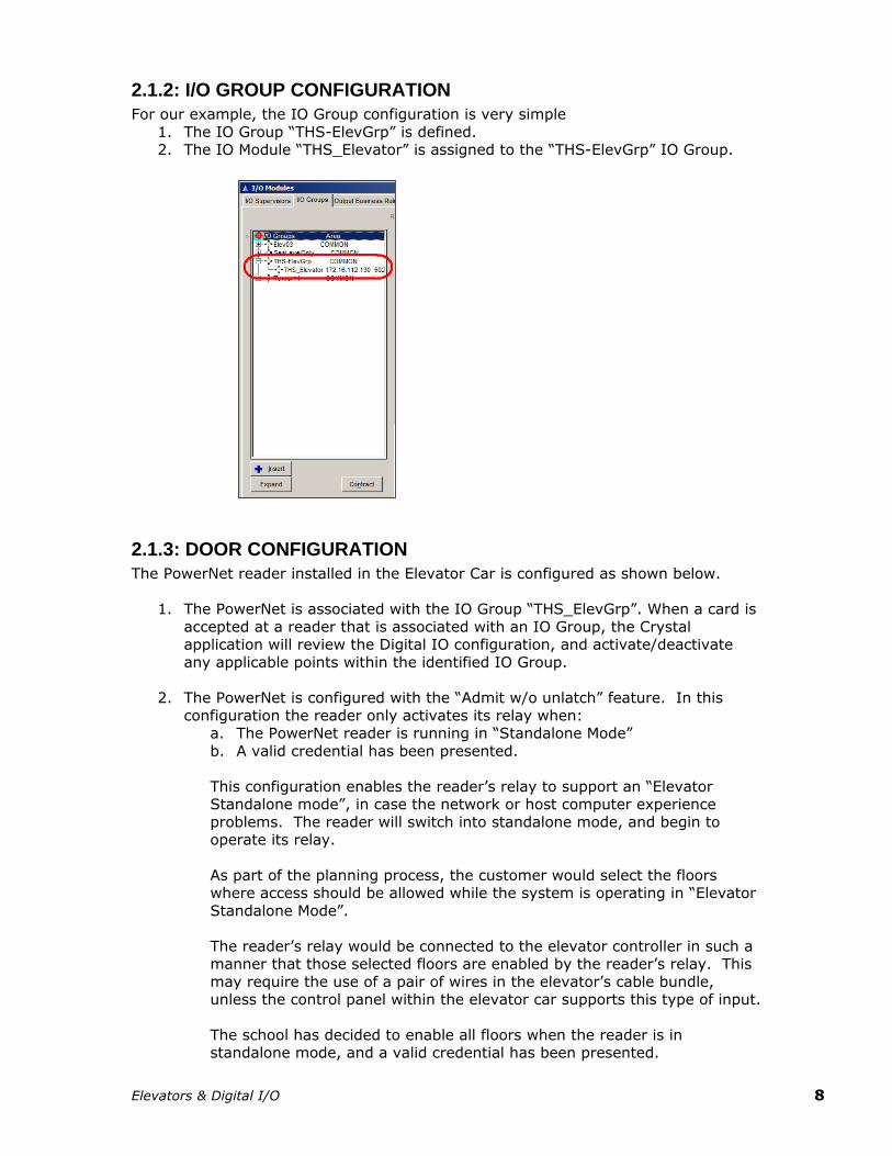
For our example, the IO Group configuration is very simple
1. The IO Group “THS-ElevGrp” is defined. 2. The IO Module “THS_Elevator” is assigned to the “THS-ElevGrp” IO Group.
2.1.3: DOOR CONFIGURATION
The PowerNet reader installed in the Elevator Car is configured as shown below.
1. The PowerNet is associated with the IO Group “THS_ElevGrp”. When a card is
accepted at a reader that is associated with an IO Group, the Crystal application will review the Digital IO configuration, and activate/deactivate
any applicable points within the identified IO Group.
2. The PowerNet is configured with the “Admit w/o unlatch” feature. In this
configuration the reader only activates its relay when: a. The PowerNet reader is running in “Standalone Mode”
b. A valid credential has been presented.
This configuration enables the reader’s relay to support an “Elevator Standalone mode”, in case the network or host computer experience
problems. The reader will switch into standalone mode, and begin to operate its relay.
As part of the planning process, the customer would select the floors where access should be allowed while the system is operating in “Elevator
Standalone Mode”.
The reader’s relay would be connected to the elevator controller in such a manner that those selected floors are enabled by the reader’s relay. This
may require the use of a pair of wires in the elevator’s cable bundle, unless the control panel within the elevator car supports this type of input.
The school has decided to enable all floors when the reader is in standalone mode, and a valid credential has been presented.
Elevators & Digital I/O 9
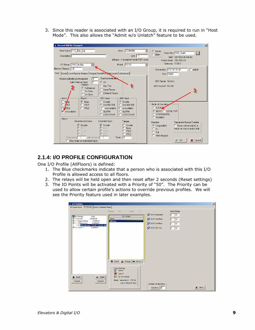
3. Since this reader is associated with an I/O Group, it is required to run in “Host Mode”. This also allows the “Admit w/o Unlatch” feature to be used.
2.1.4: I/O PROFILE CONFIGURATION
One I/O Profile (AllFloors) is defined:
1. The Blue checkmarks indicate that a person who is associated with this I/O Profile is allowed access to all floors.
2. The relays will be held open and then reset after 2 seconds (Reset settings) 3. The IO Points will be activated with a Priority of “50”. The Priority can be
used to allow certain profile’s actions to override previous profiles. We will
see the Priority feature used in later examples.
Elevators & Digital I/O 10
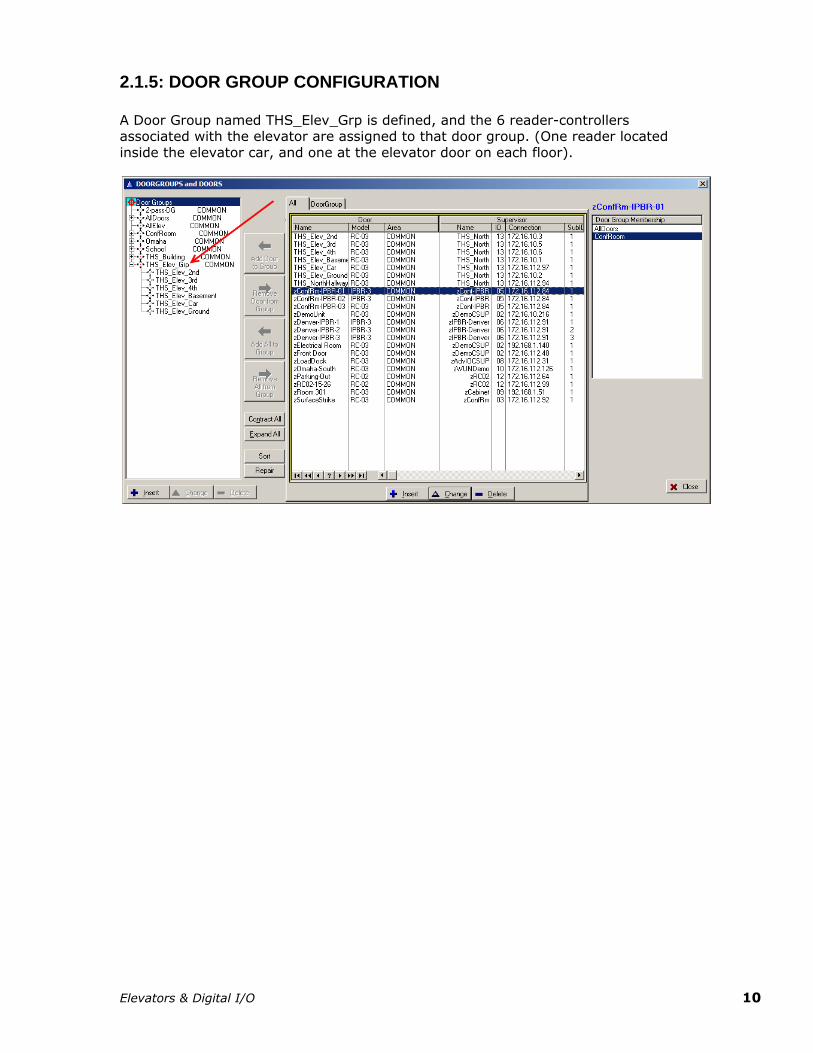
2.1.5: DOOR GROUP CONFIGURATION
A Door Group named THS_Elev_Grp is defined, and the 6 reader-controllers associated with the elevator are assigned to that door group. (One reader located
inside the elevator car, and one at the elevator door on each floor).
Elevators & Digital I/O 11
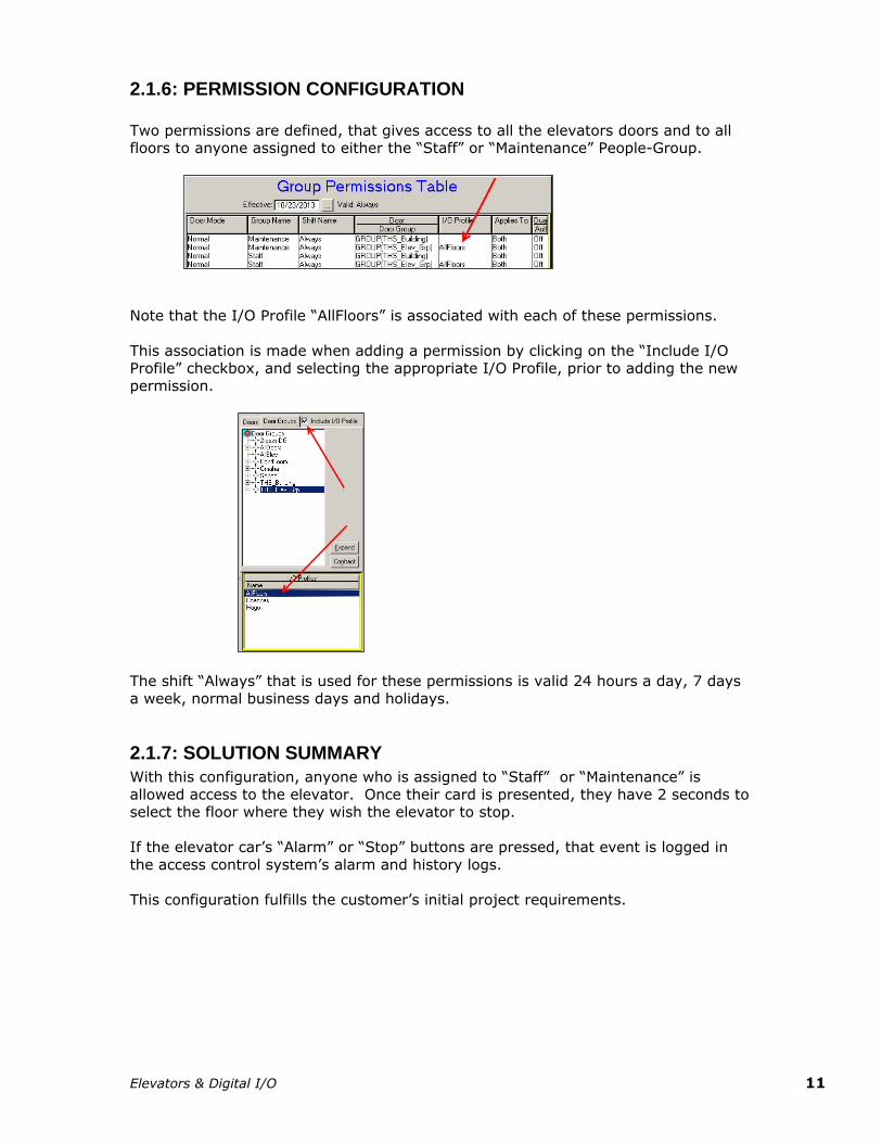
2.1.6: PERMISSION CONFIGURATION
Two permissions are defined, that gives access to all the elevators doors and to all floors to anyone assigned to either the “Staff” or “Maintenance” People-Group.
Note that the I/O Profile “AllFloors” is associated with each of these permissions.
This association is made when adding a permission by clicking on the “Include I/O Profile” checkbox, and selecting the appropriate I/O Profile, prior to adding the new
permission.
The shift “Always” that is used for these permissions is valid 24 hours a day, 7 days
a week, normal business days and holidays.
2.1.7: SOLUTION SUMMARY
With this configuration, anyone who is assigned to “Staff” or “Maintenance” is
allowed access to the elevator. Once their card is presented, they have 2 seconds to select the floor where they wish the elevator to stop.
If the elevator car’s “Alarm” or “Stop” buttons are pressed, that event is logged in
the access control system’s alarm and history logs.
This configuration fulfills the customer’s initial project requirements.
Elevators & Digital I/O 12
2.2: SUPPORTING MORE GENERAL USE OF THE ELEVATOR (CHANGE ORDER #1 )
2.2.1: CHANGE DESCRIPTION
The customer has determined that during business hours, the elevator should be
open for use by anyone. During non-business hours, only members of the “Staff” or
“Maintenance“ groups are allowed to use the elevator.
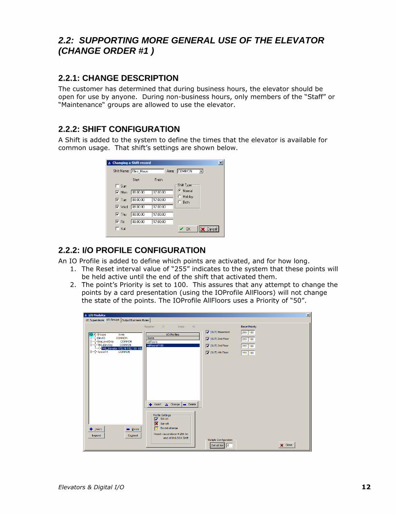
2.2.2: SHIFT CONFIGURATION
A Shift is added to the system to define the times that the elevator is available for common usage. That shift’s settings are shown below.
2.2.2: I/O PROFILE CONFIGURATION
An IO Profile is added to define which points are activated, and for how long. 1. The Reset interval value of “255” indicates to the system that these points will
be held active until the end of the shift that activated them.
2. The point’s Priority is set to 100. This assures that any attempt to change the points by a card presentation (using the IOProfile AllFloors) will not change
the state of the points. The IOProfile AllFloors uses a Priority of “50”.
Elevators & Digital I/O 13
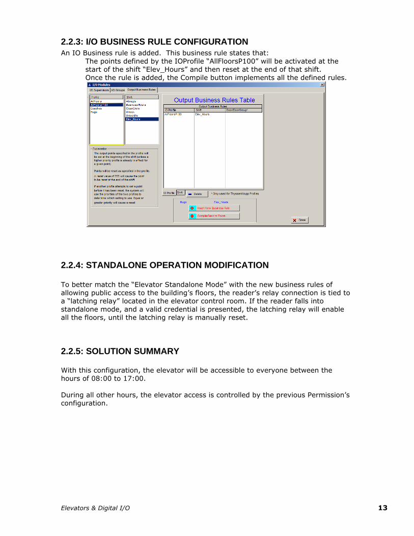
2.2.3: I/O BUSINESS RULE CONFIGURATION
An IO Business rule is added. This business rule states that:
The points defined by the IOProfile “AllFloorsP100” will be activated at the start of the shift “Elev_Hours” and then reset at the end of that shift.
Once the rule is added, the Compile button implements all the defined rules.
2.2.4: STANDALONE OPERATION MODIFICATION
To better match the “Elevator Standalone Mode” with the new business rules of
allowing public access to the building’s floors, the reader’s relay connection is tied to a “latching relay” located in the elevator control room. If the reader falls into
standalone mode, and a valid credential is presented, the latching relay will enable all the floors, until the latching relay is manually reset.
2.2.5: SOLUTION SUMMARY
With this configuration, the elevator will be accessible to everyone between the hours of 08:00 to 17:00.
During all other hours, the elevator access is controlled by the previous Permission’s configuration.
Elevators & Digital I/O 14
2.3: CONTROLLING PUBLIC ACCESS TO CERTAIN FLOORS (CHANGE ORDER #2 )
2.3.1: CHANGE DESCRIPTION
The customer wished to restrict which floors are open to public access during business hours. The Public will have access to the 2nd and 3rd Floors during the
times of 08:00 to 17:00, Monday thru Friday. The members of “Staff” and “Maintenance” will have access to all floors, at all times.
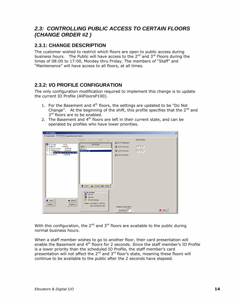
2.3.2: I/O PROFILE CONFIGURATION
The only configuration modification required to implement this change is to update
the current IO Profile (AllFloorsP100).
1. For the Basement and 4th floors, the settings are updated to be “Do Not Change”. At the beginning of the shift, this profile specifies that the 2nd and
3rd floors are to be enabled.
2. The Basement and 4th floors are left in their current state, and can be operated by profiles who have lower priorities.
With this configuration, the 2nd and 3rd floors are available to the public during normal business hours.
When a staff member wishes to go to another floor, their card presentation will enable the Basement and 4th floors for 2 seconds. Since the staff member’s IO Profile
is a lower priority than the scheduled IO Profile, the staff member’s card presentation will not affect the 2nd and 3rd floor’s state, meaning these floors will
continue to be available to the public after the 2 seconds have elapsed.
Elevators & Digital I/O 15
2.3.3: OVERRIDE CARD
The customer has requested that a method be provided that allows them to block
public access through the elevator. This capability will be supplied by a credential which is configured to reset the system so all floors will require a valid credential.
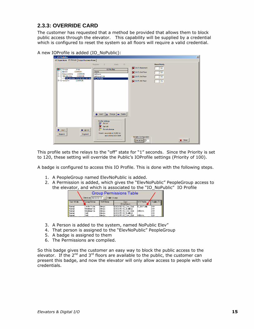
A new IOProfile is added (IO_NoPublic):
This profile sets the relays to the “off” state for “1” seconds. Since the Priority is set
to 120, these setting will override the Public’s IOProfile settings (Priority of 100).
A badge is configured to access this IO Profile. This is done with the following steps.
1. A PeopleGroup named ElevNoPublic is added. 2. A Permission is added, which gives the “ElevNoPublic” PeopleGroup access to
the elevator, and which is associated to the “IO_NoPublic” IO Profile
3. A Person is added to the system, named NoPublic Elev”
4. That person is assigned to the “ElevNoPublic” PeopleGroup 5. A badge is assigned to them
6. The Permissions are compiled.
So this badge gives the customer an easy way to block the public access to the elevator. If the 2nd and 3rd floors are available to the public, the customer can
present this badge, and now the elevator will only allow access to people with valid credentials.
Elevators & Digital I/O 16
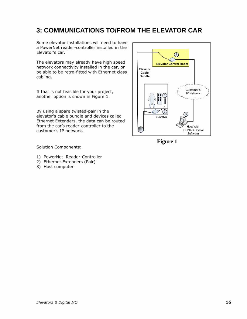
3: COMMUNICATIONS TO/FROM THE ELEVATOR CAR Some elevator installations will need to have
a PowerNet reader-controller installed in the Elevator’s car.
The elevators may already have high speed
network connectivity installed in the car, or
be able to be retro-fitted with Ethernet class cabling.
If that is not feasible for your project, another option is shown in Figure 1.
By using a spare twisted-pair in the
elevator’s cable bundle and devices called Ethernet Extenders, the data can be routed
from the car’s reader-controller to the customer’s IP network.
Figure 1 Solution Components:
1) PowerNet Reader-Controller 2) Ethernet Extenders (Pair)
3) Host computer
Elevators & Digital I/O 17
4: EXAMPLE MODBUS/TCP MODULE SETTINGS When defining the IO-Module within Crystal Matrix, some setting may vary
depending on the specific brand and module of the IO-Module being used.
Listed below are some example setting for two types of IO-Modules
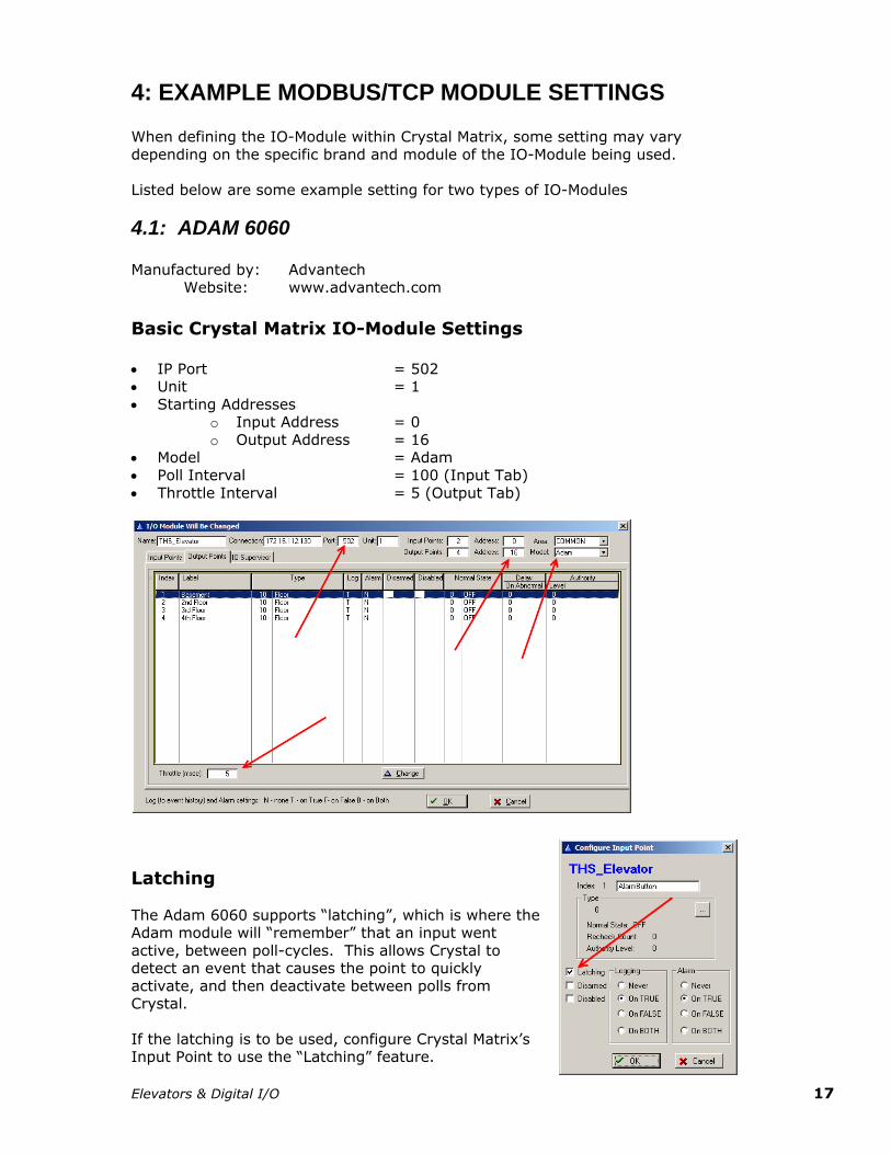
4.1: ADAM 6060
Manufactured by: Advantech
Website: www.advantech.com
Basic Crystal Matrix IO-Module Settings
IP Port = 502 Unit = 1
Starting Addresses o Input Address = 0
o Output Address = 16 Model = Adam
Poll Interval = 100 (Input Tab)
Throttle Interval = 5 (Output Tab)
Latching
The Adam 6060 supports “latching”, which is where the Adam module will “remember” that an input went
active, between poll-cycles. This allows Crystal to detect an event that causes the point to quickly
activate, and then deactivate between polls from Crystal.
If the latching is to be used, configure Crystal Matrix’s Input Point to use the “Latching” feature.
Elevators & Digital I/O 18
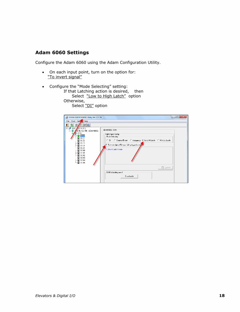
Adam 6060 Settings Configure the Adam 6060 using the Adam Configuration Utility.
On each input point, turn on the option for:
“To invert signal”
Configure the “Mode Selecting” setting: If that Latching action is desired, then
Select “Low to High Latch” option
Otherwise, Select “DI” option
Elevators & Digital I/O 19
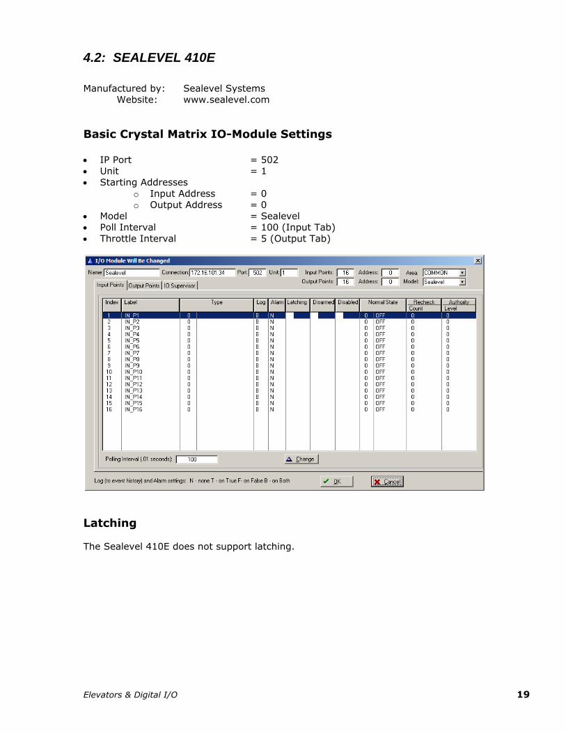
4.2: SEALEVEL 410E Manufactured by: Sealevel Systems
Website: www.sealevel.com
Basic Crystal Matrix IO-Module Settings IP Port = 502
Unit = 1 Starting Addresses
o Input Address = 0 o Output Address = 0
Model = Sealevel Poll Interval = 100 (Input Tab)
Throttle Interval = 5 (Output Tab)
Latching The Sealevel 410E does not support latching.
Elevators & Digital I/O 20
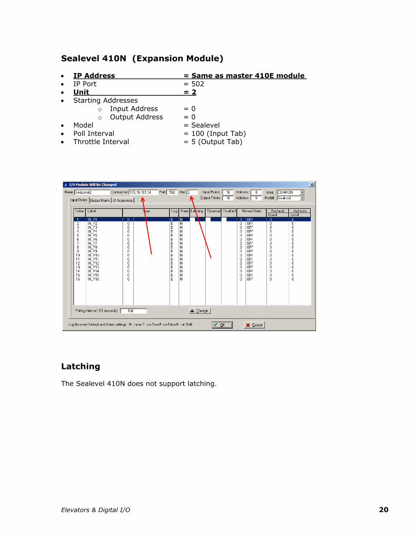
Sealevel 410N (Expansion Module)
IP Address = Same as master 410E module IP Port = 502
Unit = 2 Starting Addresses
o Input Address = 0
o Output Address = 0 Model = Sealevel
Poll Interval = 100 (Input Tab) Throttle Interval = 5 (Output Tab)
Latching The Sealevel 410N does not support latching.

Elevators & Digital I/O 21
For more information:
Web: www.isonas.com E-mail: [email protected]
Tel: 800-581-0083 x102 (toll-free) or 303-567-6516 x102 (CO)
Fax: 303-567-6991
ISONAS Headquarters:
4720 Walnut Street, Suite 200, Boulder, Colorado 80301 USA