Embed Size (px)
Citation preview

Calhoun: The NPS Institutional Archive
Theses and Dissertations Thesis Collection
2015-09
Examination of the benefits of standardized
interfaces on space systems
Lee, Jonathan
Monterey, California: Naval Postgraduate School
http://hdl.handle.net/10945/47294

NAVAL
POSTGRADUATE
SCHOOL
MONTEREY, CALIFORNIA
THESIS
Approved for public release; distribution is unlimited
EXAMINATION OF THE BENEFITS OF STANDARDIZED INTERFACES ON SPACE SYSTEMS
by
Jonathan Lee
September 2015
Thesis Advisor: Kristin Giammarco Second Reader: Mark M. Rhoades

THIS PAGE INTENTIONALLY LEFT BLANK

i
REPORT DOCUMENTATION PAGE Form Approved OMB No. 0704–0188 Public reporting burden for this collection of information is estimated to average 1 hour per response, including the time for reviewing instruction, searching existing data sources, gathering and maintaining the data needed, and completing and reviewing the collection of information. Send comments regarding this burden estimate or any other aspect of this collection of information, including suggestions for reducing this burden, to Washington headquarters Services, Directorate for Information Operations and Reports, 1215 Jefferson Davis Highway, Suite 1204, Arlington, VA 22202-4302, and to the Office of Management and Budget, Paperwork Reduction Project (0704-0188) Washington, DC 20503. 1. AGENCY USE ONLY (Leave blank) 2. REPORT DATE
September 20153. REPORT TYPE AND DATES COVERED
Master’s Thesis 4. TITLE AND SUBTITLEEXAMINATION OF THE BENEFITS OF STANDARDIZED INTERFACES ON SPACE SYSTEMS
5. FUNDING NUMBERS
6. AUTHOR(S) Lee, Jonathan 7. PERFORMING ORGANIZATION NAME(S) AND ADDRESS(ES)
Naval Postgraduate School Monterey, CA 93943-5000
8. PERFORMING ORGANIZATIONREPORT NUMBER
9. SPONSORING /MONITORING AGENCY NAME(S) AND ADDRESS(ES)N/A
10. SPONSORING/MONITORING AGENCY REPORT NUMBER
11. SUPPLEMENTARY NOTES The views expressed in this thesis are those of the author and do not reflect the official policyor position of the Department of Defense or the U.S. Government. IRB Protocol number ____N/A____.
12a. DISTRIBUTION / AVAILABILITY STATEMENT Approved for public release; distribution is unlimited
12b. DISTRIBUTION CODE A
13. ABSTRACT (maximum 200 words)
Space systems today are highly customized systems for which standardized interfaces rarely exist. A majority of the cost can be attributed to nonrecurring engineering costs, since these systems are redesigned each time a space system is procured. As new space systems are developed, the usage of standardized interface can prove to be highly advantageous.
The objective of the thesis is to identify key interfaces that can be standardized, and to determine whether the implementation of standardized interfaces on space systems can provide any added benefits such as cost savings, schedule reductions, and a rapid replenishment capability if a system was lost.
A satellite functional analysis was performed using IDEF0 models, which indicated that multiple interfaces within each subsystem can be standardized. The biggest return on investment in terms of interface standardization would come from the Command and Data Handling and Electrical Power subsystem, since each component onboard will require, at a minimum, a single data and power interface. As a result of utilizing a standard interface, cost savings can be realized through efficiencies in design and manufacturing, and allow for a rapid replenishment capability for any systems that are lost due to any type of failure. The research concludes with recommendations for standardization by subsystem and function, based on the IDEF0 analysis.
14. SUBJECT TERMSinterface standardization, interface, standardization, satellites
15. NUMBER OFPAGES
125 16. PRICE CODE
17. SECURITYCLASSIFICATION OF REPORT
Unclassified
18. SECURITYCLASSIFICATION OF THIS PAGE
Unclassified
19. SECURITYCLASSIFICATION OF ABSTRACT
Unclassified
20. LIMITATION OFABSTRACT
UU NSN 7540–01-280-5500 Standard Form 298 (Rev. 2–89)
Prescribed by ANSI Std. 239–18

ii
THIS PAGE INTENTIONALLY LEFT BLANK

iii
Approved for public release; distribution is unlimited
EXAMINATION OF THE BENEFITS OF STANDARDIZED INTERFACES ON SPACE SYSTEMS
Jonathan Lee Civilian, Space Exploration Technologies
B.S., California State Polytechnic University, Pomona, 2005
Submitted in partial fulfillment of the requirements for the degree of
MASTER OF SCIENCE IN SYSTEMS ENGINEERING MANAGEMENT
from the
NAVAL POSTGRADUATE SCHOOL September 2015
Author: Jonathan Lee
Approved by: Dr. Kristin Giammarco Thesis Advisor
Mark M. Rhoades Second Reader
Dr. Ronald Giachetti Chair, Department of Systems Engineering

iv
THIS PAGE INTENTIONALLY LEFT BLANK

v
ABSTRACT
Space systems today are highly customized systems for which standardized interfaces
rarely exist. A majority of the cost can be attributed to nonrecurring engineering costs,
since these systems are redesigned each time a space system is procured. As new space
systems are developed, the usage of standardized interface can prove to be highly
advantageous.
The objective of the thesis is to identify key interfaces that can be standardized,
and to determine whether the implementation of standardized interfaces on space systems
can provide any added benefits such as cost savings, schedule reductions, and a rapid
replenishment capability if a system was lost.
A satellite functional analysis was performed using IDEF0 models, which
indicated that multiple interfaces within each subsystem can be standardized. The biggest
return on investment in terms of interface standardization would come from the
Command and Data Handling and Electrical Power subsystem, since each component
onboard will require, at a minimum, a single data and power interface. As a result of
utilizing a standard interface, cost savings can be realized through efficiencies in design
and manufacturing, and allow for a rapid replenishment capability for any systems that
are lost due to any type of failure. The research concludes with recommendations for
standardization by subsystem and function, based on the IDEF0 analysis.

vi
THIS PAGE INTENTIONALLY LEFT BLANK

vii
TABLE OF CONTENTS
I. INTRODUCTION........................................................................................................1 A. IMPORTANCE AND OBJECTIVE ..............................................................1 B. RESEARCH QUESTIONS .............................................................................6 C. BENEFITS OF THESIS INVESTIGATION ................................................6
II. BACKGROUND AND METHODOLOGY ..............................................................7 A. HISTORY OF SPACE SYSTEMS .................................................................7 B. SATELLITE ARCHITECTURE .................................................................20 C. INTERFACES ................................................................................................30 D. STANDARDIZATION ..................................................................................31
III. MODELING AND ANALYSIS ................................................................................37 A. SYSTEMS ENGINEERING .........................................................................37 B. SATELLITE SUBSYSTEM MODELING ..................................................41
IV. CONCLUSION ..........................................................................................................73 A. RESEARCH QUESTION EVALUATION .................................................73 B. FURTHER WORK AND RESEARCH .......................................................77
APPENDIX A. TRL READINESS LEVEL (FROM NASA 2015D) ................................79
APPENDIX B. IDEF0 A-0 DIAGRAMS ............................................................................81
LIST OF REFERENCES ......................................................................................................95
INITIAL DISTRIBUTION LIST .......................................................................................103

viii
THIS PAGE INTENTIONALLY LEFT BLANK

ix
LIST OF FIGURES
Figure 1. NASA TRL (from NASA 2010) ........................................................................2 Figure 2. Sputnik 1 (from NASA 2015i) ...........................................................................7 Figure 3. Explorer 1 (from NASA 2015h) ........................................................................8 Figure 4. Advanced Extremely High Frequency (from Lockheed 2015) ........................10 Figure 5. Tracking and Data Relay Satellite (from NASA 2013a) .................................10 Figure 6. Remote Sensing Satellites (from NASA 2008b) .............................................11 Figure 7. GPS III (from Lockheed Martin 2015c) ..........................................................11 Figure 8. Hubble Space Telescope (from Encyclopedia Britannica Online 2015) .........12 Figure 9. James Webb Space Telescope (from NASA 2008a) .......................................13 Figure 10. Advanced Extremely High Frequency (from Lockheed Martin 2015b) ..........14 Figure 11. Communication Satellite Cost Breakdown (from RAND 2008) .....................16 Figure 12. Satellites Launched in Orbit by Country (from Lafleur 2015) ........................19 Figure 13. RAD750 6U CPU Architecture (from BAE 2015c) ........................................22 Figure 14. ESA Command and Data Handling Architecture (from European Space
Agency 1970) ...................................................................................................23 Figure 15. GOES EPS Subsystem (from NASA 2015e) ...................................................24 Figure 16. Star Tracker (from Ball 2015)..........................................................................25 Figure 17. Torque Rod (from Spaceflight Industries 2015) ..............................................26 Figure 18. Reaction Wheel (from Rockwell Collins 2015)...............................................26 Figure 19. Honeycomb Structure (from European Space Agency 2015) ..........................27 Figure 20. RTD Probe (from Correge 2015) .....................................................................28 Figure 21. MLI (from Aerospacefab 2015) .......................................................................29 Figure 22. Space Communication Architecture (from Massachusetts Institute of
Technology 2015) ............................................................................................30 Figure 23. SUMO Notional Transition Plan (from Collins 2013) ....................................35 Figure 24. Systems Engineering Principles (from MITRE 2013) .....................................37 Figure 25. Systems Engineering V Diagram (from Kossiakoff, Sweet, Seymour, and
Biemer 2011) ...................................................................................................40 Figure 26. Systems Engineering Activities and Documents (from Kossiakoff et al.
2011) ................................................................................................................40 Figure 27. IDEF0 Diagram (from Kossiakoff et al. 2011) ................................................41 Figure 28. IDEF0: Satellite System Context Diagram ......................................................42 Figure 29. IDEF0: Space System Decomposition .............................................................43 Figure 30. IDEF0: Command and Data Handling Subsystem ..........................................45 Figure 31. IDEF0: Command Authentication ...................................................................46 Figure 32. IDEF0 A-0: Sync Word Frame Lock ...............................................................47 Figure 33. IDEF0 A-0: Unparse Commands .....................................................................48 Figure 34. IDEF0: Provide System Timing.......................................................................49 Figure 35. IDEF0: Perform Fault Management ................................................................50 Figure 36. IDEF0 A-0: Execute Stored Command Sequences .........................................51 Figure 37. IDEF0: Run Flight Software ............................................................................52 Figure 38. IDEF0: Manage Internal/External Data Bus ....................................................53

x
Figure 39. IDEF0: Perform Memory Storage ...................................................................54 Figure 40. IDEF0: Perform Spacecraft Control Processor Computation ..........................55 Figure 41. IDEF0: Provide Telemetry Conditioning.........................................................56 Figure 42. IDEF0: Provide Attitude Control .....................................................................58 Figure 43. IDEF0: Actuate Attitude Control System ........................................................58 Figure 44. IDEF0: Attitude Sensing ..................................................................................59 Figure 45. IDEF0: Provide RF Communication ...............................................................60 Figure 46. IDEF0: Space Ground Link Systems ...............................................................61 Figure 47. IDEF0: Power Subsystem ................................................................................62 Figure 48. IDEF0: Generate Power ...................................................................................63 Figure 49. IDEF0: Provide Power .....................................................................................64 Figure 50. IDEF0: Charge Batteries ..................................................................................65 Figure 51. IDEF0: Regulate System Power ......................................................................66 Figure 52. IDEF0: Regulate Thermal Environment Subsystem........................................67 Figure 53. IDEF0: Provide Heat........................................................................................68 Figure 54. IDEF0: Sense Temperatures ............................................................................69 Figure 55. IDEF0: Dissipate Heat .....................................................................................70 Figure 56. IDEF0: Acquire Payload Data Subsystem .......................................................71 Figure 57. IDEF0 A-0: Generate System Timing .............................................................81 Figure 58. IDEF0 A-0: Update System Timing from GPS ...............................................82 Figure 59. IDEF0 A-0: Read Hardware Data ....................................................................82 Figure 60. IDEF0 A-0: Generate and Format Telemetry ..................................................83 Figure 61. IDEF0 A-0: Executes Ground Commands ......................................................83 Figure 62. IDEF0 A-0: CRC Error Correction ..................................................................84 Figure 63. IDEF0 A-0: Monitors System Health ..............................................................84 Figure 64. IDEF0 A-0: Format System Data ....................................................................85 Figure 65. IDEF0 A-0: Transmit/Receive High Speed Data Rates ...................................85 Figure 66. IDEF0 A-0: Run Instructions from FSW .........................................................86 Figure 67. IDEF0 A-0: Perform Logic Calculations .........................................................86 Figure 68. IDEF0 A-0: Transmit and Receive Data ..........................................................87 Figure 69. IDEF0 A-0: Decrypt Received Data ................................................................87 Figure 70. IDEF0 A-0: Encrypt Data ................................................................................88 Figure 71. IDEF0 A-0: Amplify Received Signal .............................................................88 Figure 72. IDEF0 A-0: Provide Rotation ..........................................................................89 Figure 73. IDEF0 A-0: Provide Angular Rotation ............................................................89 Figure 74. IDEF0 A-0: Provide Thrust .............................................................................90 Figure 75. IDEF0 A-0: Provide Stabilization ....................................................................90 Figure 76. IDEF0 A-0: Maintain Orientation ....................................................................91 Figure 77. IDEF0 A-0: Determine Magnetic Field ...........................................................91 Figure 78. IDEF0 A-0: Measures Degrees of Freedom ....................................................92 Figure 79. IDEF0 A-0: Determine Direction of the Sun and Earth ..................................92 Figure 80. IDEF0 A-0: Provide Position ...........................................................................93 Figure 81. IDEF0 A-0: Track Stars ...................................................................................93 Figure 82. IDEF0 A-0: Rotate Solar Arrays......................................................................94 Figure 83. IDEF0 A-0: Sun Tracking ................................................................................94

xi
LIST OF TABLES
Table 1. International Organizations and Associations ...................................................1 Table 2. NASA Space Mission Failures ..........................................................................3 Table 3. On-Board Processors for Space Systems ...........................................................4 Table 4. Comparison of Commercial Processors to Space System Processors ...............5 Table 5. Satellite Types ....................................................................................................9 Table 6. Advantages of Space Technology (from International Space Exploration
Coordination Group 2013) ...............................................................................15 Table 7. Indirect Disadvantages of Space ......................................................................17 Table 8. Satellite Subsystems Defined ...........................................................................20 Table 9. Satellite Interface Types ..................................................................................31 Table 10. Commercial Standardized Satellite Bus...........................................................33 Table 11. Standardization Efforts Led by the U.S. Government .....................................34 Table 12. Stakeholders’ Analysis.....................................................................................38 Table 13. Key Performance Parameters ...........................................................................39 Table 14. Interfaces Recommended for Standardization .................................................75

xii
THIS PAGE INTENTIONALLY LEFT BLANK

xiii
LIST OF ACRONYMS AND ABBREVIATIONS
5CAT category 5 cable
ACS Attitude Control subsystem
AEHF advanced extremely high frequency
ASME American Society of Mechanical Engineers
BOL beginning of life
C&DH Command and Data Handling
CCSDS Consultative Committee for Space Data Systems
CUBESATS cube satellites
DIN German Institute for Standardization
EOL end of life
EPS Electrical Power subsystem
ESA European Space Agency
GEO geosynchronous Earth orbit
GPS Global Positioning System
GSE ground support equipment
HST Hubble Space Telescope
IA&T integration assembly and test
IEEE Institute of Electrical and Electronics Engineers
INCOSE International Council on Systems Engineering
ISO International Organization for Standardization
ISS international space station
JWST James Webb Space Telescope
KPP key performance parameters
LD/MT launch detection and missing tracking
LEO low Earth orbit
MEO medium Earth orbit
MILSATCOM military satellite communication
MILSTAR military strategic and tactical relay
MIL-STD-1553 military standard 1553 digital communication bus
MLI multi-layer insulation

xiv
MOSA Modular Open System Architecture
NASA National Aeronautics and Space Administration
NRE nonrecurring engineering
NRO National Reconnaissance Office
ORS Operational Responsive Space
R&D research and development
RF radio frequency
RS-422 Electrical Characteristics of Balanced Voltage Digital Interface Circuits
RTD remote temperature detector
SADA solar array drive assembly
SAE Society of Automotive Engineers
SCS stored command sequences
SEMP systems engineering management plan
SGLS space ground link system
SMC Space and Missile Center
SOIS standardization of onboard data interfaces and services
SPACEX Space Exploration Technologies
SUMO Space Universal Modular Architecture
TRL technology readiness level
USB universal serial bus
USD United States dollars
USG United States government
V volt
WIFI wireless fidelity

xv
EXECUTIVE SUMMARY
Due to the tremendous advantage that space systems offer, there has been a push by
governments and commercial industries around the world to field as many space systems
as their budgets allow. Over the past decade, decreasing budgets have forced government
agencies and commercial industries to procure systems that are at a fraction of the cost as
compared to older systems and yet retain the same performance capabilities. This added
market pressure is forcing manufacturers to be more competitive and innovative with
their product offerings. It is a generally accepted principle that improvements in design
and the reduction of manufacturing cost will benefit most stakeholders. A study on
standardization led by the German Institute of Standardization (DIN) has shown that
standardization has provided short- and long-term benefits with regard to costs and being
more competitive than those companies that did not participate. In addition, standards
have proven to lower production cost and research and development (R&D) cost,
increase supplier base and cooperation between businesses, increase overall product
safety and reliability, and create positive stimulation for innovation (Verlag 2008).
The primary research questions are as follows: Can standardized interfaces on
space systems provide any added benefits? If so, what added benefits do they provide to
the consumer and manufacturer? Do they save overall total system cost or schedule? Do
they provide a rapid replenishment capability when a system capability is lost? What are
the interfaces that can be standardized?
In order to frame the problem into context, the thesis approach utilized systems
engineering principles and processes to help carve out the problem into manageable
pieces. As part of the initial systems engineering efforts, a stakeholder’s analysis was
performed to identify key stakeholders and to ascertain the level of involvement and
interest in standardization efforts; see Table 1. The next sizeable step was the
development of an engineering model using CORE to help generate IDEF0 diagrams,
which illustrated system functions and interactions through its inputs, outputs, controls,
and mechanisms as shown in and Figure 1.
xvi
Table 1. Stakeholders’ Analysis
Stakeholders Involvement
Operational Users
Heavily involved; End users of the data and the system. Need to understand the capabilities and limitations of the system
Satellite Manufacturers Heavily involved; Need to know what to build and how to test the functionality of the system
Rocket Manufacturers Moderately involved; Need to understand the rocket to payload interface
Design Engineers
Heavily involved; Need to understand the interfaces in order to design to the mission specific requirements
Systems Engineers Heavily involved; Chief architects of the system and subsystems. Need to understand limitations in design
Suppliers Moderately involved; Need to supply components and raw materials for the system
Government Offices and Organizations - Domestic and International
Heavily involved; Need to define standards within their respective field
Figure 1. IDEF0 Diagram (from Kossiakoff, Sweet, Seymour, and Biemer 2011)

xvii
After careful analysis and examination of all the functional system interfaces
onboard a satellite, the resulting conclusion is that implementing interface standards can
provide benefits to most stakeholders. In particular, manufacturers can reduce
nonrecurring engineering (NRE) hours spent on specifying and designing hundreds of
interfaces and utilize the freed up resource to further advance the capability of their
product offerings thus reducing overall system risk, and improve upon current
manufacturing processes. Cost to produce these systems will decrease over time since
existing ground support equipment (GSE) and test equipment can be utilized to perform
functional checkouts and other support related functions. In addition, the overall technical
staff will be more experienced and competent in dealing with issue resolution on a
standardized interface as opposed to learning a new interface and all the problems
associated with the new design, thus allowing management greater freedom to reallocate
resources as necessary. These cost savings in production and reduction in engineering
hours will eventually be reflected in the overall price tag of these systems.
The end users of the system also stand to benefit tremendously from the
utilization of standardized interfaces. As more engineering resources are allocated to
developing and improving on existing and new functionalities, the resulting systems will
be more affordable, reliable and capable than their predecessors. Another significant
advantage of standardization is the rapid replenishment capability of a lost capability if
for any reason the system capability is lost due to a launch failure or onboard failure. The
future outlook of the space industry is positive as it has the most to gain from
standardization efforts. It is up to industry partners, standards organizations, and
stakeholders to ensure that the space industry takes the next logical step by developing
and utilizing interface standards that has been proven to be quite advantageous for their
own respective industry.

xviii
References
Kossiakoff, A., Sweet, W., Seymour, S., Biemer, S., 2011. Systems Engineering Principles and Practice. New Jersey. John Wiley & Sons, Inc.
Verlag, Beuth. 2008. “Economic Benefits of Standardization – Summary of Results.” DIN German Institute of Standardization 1.

xix
ACKNOWLEDGMENTS
I would like to express my deepest appreciation for my thesis advisor, Dr. Kristin
Giammarco, for her tremendous support, guidance, and mentorship that spanned the
course of three years. Her encouraging words kept me motivated throughout this
endeavor.
I would also like to thank Professor Mark Rhoades for taking the time to read
through my thesis and for providing me the necessary systems engineering feedback to
my thesis topic.
I would like to acknowledge and thank Ms. Barbara Berlitz for taking the time to
review my thesis.
I would also like to thank Ms. Alice Lee for her words of encouragement and
support throughout my three years as a student at the Naval Postgraduate School.

xx
THIS PAGE INTENTIONALLY LEFT BLANK

1
I. INTRODUCTION
A. IMPORTANCE AND OBJECTIVE
Throughout the twenty-first century, the adoption of standards has changed the
way the world operates when conducting business domestically and abroad. Many
international organizations and associations have been formed along with government
agencies to oversee the development and adherence of standards for every imaginable
industry. These organizations and associations are not limited to those identified in Table
1.
Table 1. International Organizations and Associations
Organization / Associations Founded References
American Society of Mechanical Engineers 1880 (ASME 2015)
Society of Automotive Engineers 1905 (SAE 2015)
American National Standards Institute 1918 (ANSI 2015)
International Organization for Standardization 1947 (ISO 2015)
Institute of Electrical and Electronics Engineers 1963 (IEEE 2015)
Consultative Committee for Space Data Systems 1982 (CCSDS 2015)
International Council on Systems Engineering 1990 (INCOSE 2015)
In the space industry, the adoption rate of standards and advancements in
technology have not been widely explored due to multiple factors stemming from overall
system risk aversion, bad experiences with technology readiness, and insufficient data
that demonstrates that standardization will provide any benefits (Borky and Singaraju
1995). The lack of a uniformed approach has shown to cause schedule slippages, project
cost overruns, and inability to garner stakeholder participation for most projects. In an
attempt to differentiate their product offerings, competing manufacturers develop highly

2
customized system that provides the best capability at minimum weight (Borky and
Singaraju 1995).
The budgeted nonrecurring engineering (NRE) hours for any space system
account for an unprecedented amount of the overall budget since each system interface is
redesigned for each new mission. The financial price tag of these systems can drastically
vary in cost from $40,000 United States dollars (USD) for Cube Satellites (CubeSat)
(Space 2004) to over $8.7 billion USD for military and scientific satellites (Space 2011)
depending on the requirements leveraged on the system. Additional technology readiness
requirements known as the Technology Readiness Levels (TRL) may drive additional
cost to ensure that the components and designs being utilized have gone through rigorous
testing to ensure overall mission success. Figure 1 illustrates the National Aeronautics
and Space Administration (NASA) TRL level for which each component must be
screened before it is placed onboard any government space system. This added level of
scrutiny is attributed to previous lessons learned during the development of these systems
and past failures as identified in Table 2. Appendix A further defines each TRL level in
greater detail.
Figure 1. NASA TRL (from NASA 2010)

3
Table 2. NASA Space Mission Failures
Year Mission Failure References
1990 Hubble Space Telescope Mirror Distortion (Broad 1990)
1998 Mars Climate Orbiter Software failure (Sawyer 1999)
1999 Mars Polar Lander
Premature engine termination
during re-entry
(JPL 2000)
1999 Deep Space 2 Radio equipment, Batteries (JPL 2000)
2001 Genesis Failed Parachute (NASA 2015f)
Due to multiple high-profile mission failures identified in Table 2, there has not
been a huge drive for adopting new technologies in favor of utilizing existing, proven
designs. For instance, the processors used onboard these expensive and complex space
systems, shown in Table 3, are considered archaic by today’s processing standards. A
majority of the cell phone processors used today are more than capable of processing data
on an order of magnitude or greater than that of the latest spacecraft processor as shown
in Table 4. In addition, there is a huge discrepancy in cost versus capability. The average
cost of cell phone processors is $30 USD (Teardown 2015), whereas space systems
processors range from a figure of $200K USD and higher (Rhea 2002). The difference in
price is mainly attributed to volume pricing and differences in technology. Space certified
processors are designed to be more rugged, and they must be capable of operating in an
environment of constant radiation and huge thermal fluctuations. If additional space
systems were fielded, the price of space certified processors will decrease due to volume
pricing.

4
Table 3. On-Board Processors for Space Systems
Mission Processor Date References
Cassini 1750A 1980 (Webster 2006)
Space Shuttle AP-101 1981 (NASA 2015b)
Galileo 1802 1976 (NASA 2015c)
Hubble Space Telescope 80486 1986 (Lytle 2008)
Sojourner Intel 80C85 1977 (NASA 1997)
Mars Global Surveyor 1750A 1980 (NASA 1996)
Spirit Rover RAD6000 1997 (BAE 2015a)
Opportunity Rover RAD6000 1997 (BAE 2015a)
Curiosity RAD750 2001 (BAE 2015a)
AEHF RAD750 2001 (BAE 2015a)

5
Table 4. Comparison of Commercial Processors to Space System Processors
Mission Processor Speed References
Apple iPhone 6 A8 1.4 GHz (Smith 2014)
AEHF RAD750 110 – 132 MHz (BAE 2015b)
Spirit Rover RAD6000 25 MHz (BAE 2015d)
Hubble Space Telescope 80486 25 – 100 MHz (Intel 2008)
Sojourner Intel 80C85 2 MHz (NASA 1997)
Mars Global Surveyor 1750A 1 – 20 MHz (NASA 1996)
Spirit Rover RAD6000 2.5 – 33 MHz (BAE 2015d)
Opportunity Rover RAD6000 2.5 – 33 MHz (BAE 2015d)
Curiosity RAD750 110 – 200 MHz (BAE 2015b)
Luckily for the space industry, there has been a revival in commercial interest
from investors who have found a business opportunity prompting them to enter the once
impenetrable aerospace market: Elon Musk with Space Exploration Technologies
(SpaceX), Richard Branson with Virgin Galactic, and Jeff Bezos with Blue Origin. All of
these entrepreneurs have invested billions of privately funded dollars into their respective
companies to challenge the dominant commercial aerospace giants such as Northrop
Grumman, Boeing, Lockheed Martin, ATK, Orbital, and Space Systems Loral. Each
respective company has found a market niche and has developed its respective space
systems, but none has yet to develop a unified standard that will fundamentally make
space more affordable for everyone.
The development of a universally accepted set of standardized interface will help
alleviate concerns when it comes to the adoption of new technology. The trend for new
procured space systems have shifted to a modular open architecture being led by
governments (ORS 2015) and space organizations around the world (CCSDS 2015). This

6
calculated move in the market is being driven by the decrease in funding by government
organizations and commercial industries to procure these systems. As such, profit
margins are also decreasing for the commercial industry, which means that the companies
that partake in the space business must be more innovative with their design,
manufacturing, and integration processes in order to be relevant.
B. RESEARCH QUESTIONS
This thesis research plans to address the following research questions: Can the
implementation of standardized interfaces on space systems provide any added benefits?
If so, what added benefits do they provide to the consumer or manufacturer? Do they
save overall system cost? Schedule? Do they provide a rapid replenishment capability
when a system capability is lost?
C. BENEFITS OF THESIS INVESTIGATION
This thesis research provides the stakeholders within the space system community
with an initial framework for a space system interface that can be targeted for
standardization. The standardized space system model was developed as part of this
research, and can be applied to further extrapolate additional data about system interface
interactions, and expanded to include ground system and space systems interactions.
The resulting conclusions from this research determine whether a framework
architecture targeting standardizing specific system interfaces can reduce NRE cost,
improve system risk, address system weight concerns, and provide recommendations on
whether or not the stakeholder community should pursue an interface standard that will
require the involvement and acceptance of the greater space community and its industry
partners.

7
II. BACKGROUND AND METHODOLOGY
A. HISTORY OF SPACE SYSTEMS
To understand the need to address space system interface standardization, there is
a need to understand the history of space systems. The development of rocket technology
has made it possible for the human race to launch satellites in space, which was achieved
with the help of Konstantin Tsiolkovsky, Robert Goddard, and Wernher von Braun. Their
work cemented the fundamental understanding of rocket technology, which led to an
even greater achievement by the former Soviet Union when it launched the first satellite
to ever orbit earth on October 4, 1957, as depicted in Figure 2 (NASA 2015a).
Figure 2. Sputnik 1 (from NASA 2015i)

8
During the time of the Cold War, the launch of Sputnik 1 by the USSR caused a
sense of panic for the American public and government. The United States scrambled to
develop and launch a space system to counter what the Soviet Union had done with
Sputnik 1. And on January 31, 1958, the United States launched Explorer 1 into orbit as
depicted in Figure 3 (Aerospace 2015). From that period forward, the utilization of space
systems has been increasing exponentially due to the numerous advantages these systems
provide. As more space systems were designed and fielded, minimal amount of research
and engineering resources were allocated to understanding these key system interfaces
and their complex interactions. And as time progressed, technology advancements and
our understanding of space have evolved the design of these space systems in both size
and complexity (Holguin and Labbee 1988). The extensive design changes resulted in the
addition of multiple system interfaces that required additional support systems utilized by
the launch vehicle and ground systems (Holguin and Labbee 1988).
Figure 3. Explorer 1 (from NASA 2015h)

9
1. Satellite Systems
Today’s satellite systems are designed to monitor the Earth from afar by means of
remote sensing sensors for scientific and/or military purposes. These systems are capable
of providing secure communication across vast distances where the presence of ground
communication infrastructure is unreliable or nonexistent. They provide the warfighter
and civilian community a unified navigational standard coordinate system that is utilized
to provide worldwide navigation. For the scientific community, these systems allow
scientists to perform scientific and exploratory activities to further mankind’s
understanding of the universe. Table 5 identifies the various satellite types and their
typical orbits as shown in the subsequent figures.
These systems are typically funded by governments who have the financial means
to procure and operate these expensive systems. Russia, China, Japan, and the United
States lead the world in operating the vast majority of the satellites currently in orbit. And
as space becomes more affordable due to improvements in manufacturability and
standardization of components and systems, there will most likely be an increase of
satellite system procurement from new nations that have been kept out of the space arena
due to the total cost of these systems.
Table 5. Satellite Types
Satellite Type Orbit Usage Figures
Communication GEO, Polar Military, Civil, Commercial 4,5
Remote Sensing LEO, GEO Military, Civil, Commercial 6
Navigation MEO Military, Civil, Commercial 7
Science and Exploration LEO, Deep space Civil 8

10
Figure 4. Advanced Extremely High Frequency (from Lockheed 2015)
Figure 5. Tracking and Data Relay Satellite (from NASA 2013a)

11
Figure 6. Remote Sensing Satellites (from NASA 2008b)
Figure 7. GPS III (from Lockheed Martin 2015c)
12
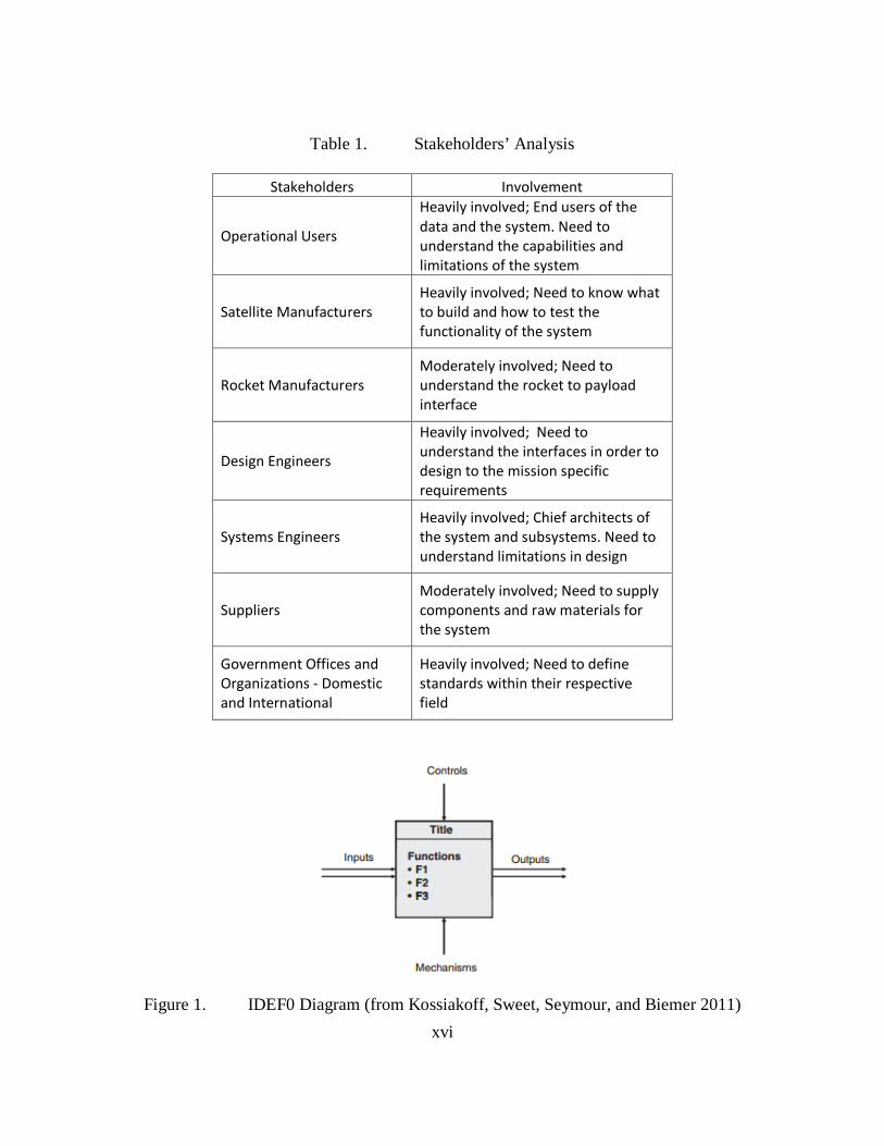
Figure 8. Hubble Space Telescope (from Encyclopedia Britannica Online 2015)
a. Satellite Definition
Satellites have been orbiting the earth since 1957 and have provided vital data for
commercial, civil, and military users. NASA defines a satellite as a machine that is
launched into space and orbits a celestial body in space (NASA 2013b). Today,
thousands of these satellites are monitoring the earth by capturing pictures to help
meteorologists predict weather and track hurricanes a shown in Figure 6. Other systems
are capturing images of planets, stars, and galaxies that are light years away to help
scientists better understand the universe as shown in Figure 8. While commercial and
military systems are typically used for communications, such as transmitting TV signals,
and data or phone calls around the world by means of encrypted communication as
shown in Figure 4 and Figure 5 (NASA 2013b).
To give a perspective of how these systems can vary in terms of capability and
design, Figure 9 shows a civil satellite used to study the universe whereas Figure 10 is the
latest military communication satellite. Figure 9 is the James Webb Space Telescope
(JWST), which is representative of a telescopic scientific satellite, and will one day
replace the Hubble Space Telescope (HST). The primary objective of the JWST is to

13
study the different phases in history of the Universe, ranging from the Big Bang up to the
formation of the solar systems we see today (NASA 2015g).
Figure 10 shows the Advanced Extremely High Frequency (AEHF) military
communication satellite. The AEHF satellite is the latest military protected
communication satellite that is designed to provide global jam-resistance communication.
It is the replacement for the Military Strategic and Tactical Relay (MILSTAR)
constellation of six satellites, which was launched between 1994 and 2003 (USAF 1995).
Figure 9. James Webb Space Telescope (from NASA 2008a)

14
Figure 10. Advanced Extremely High Frequency (from Lockheed Martin 2015b)
b. Operational Environment
In order to support the various scientific, military, and civil missions, these
systems and interfaces must be designed to operate in an unforgiving environment where
the temperature can fluctuate dramatically, cope with the constant bombardment of
cosmic radiation, operate in a near zero gravitational environment, and possess the
capability to resolve any onboard failures without any ground servicing capability besides
updates in software.
c. Weight and Structural Designs
The weight and structural designs of these systems will vary from mission to
mission as they are designed to be optimized in terms of weight, size, and shape. Any
new system and interface designs must be structurally capable to survive the acoustic and
dynamic environments of launch and ensure that minimal weight is added to the overall
system. The payload design must take into account the capability of the launch vehicle to
ensure that their satellite system can survive the harsh dynamic environment of launch
and ultimately reach the desired operational orbit. The smaller class satellite systems can
weigh between 1–200 kg (NASA 2015j), whereas larger satellite systems can weigh from
5,000–6,500 kg (Boeing 2015).

15
2. Advantages of Space
In order to understand why there is a need to improve on the current design and
manufacturing of space systems, there is a need to understand how important these
systems are for humankind. Space offers the highest vantage point of the earth, which
allows for an unprecedented around the clock coverage over geographic areas of interest.
For the military, space systems provides a means to detect and track missile launches, a
secure means to transmit information across vast distances, to perform mission operation
planning, weather forecast and prediction, navigation, and reconnaissance. And for the
civilian and scientific community, it provides a means to analyze and study the changing
world due to climate change, rising sea levels, and deforestation.
The advancement of technology for space systems has been made possible
through research and development, and scientific experiments conducted in space
onboard the ISS. The results from these experiments have yielded breakthroughs in the
formulation of new material properties that are stronger, lighter, and more resilient
(NASA 2015k). In addition, scientific experiments conducted on the ISS on the effects of
zero gravity on various living organisms have led to promising data, which ultimately
furthers mankind’s understanding about space and how to plan and prepare for future
exploratory manned missions beyond this planet’s orbit (NASA 2015l). Table 6 provides
a broad spectrum of other direct and indirect benefits that stem from the advancement of
space technology.
Table 6. Advantages of Space Technology (from International Space Exploration Coordination Group 2013)
Direct Benefits Indirect Benefits Scientific knowledge is generated Economic Prosperity National technical competence is improved Health Innovation is transferred to new application Environmental Benefits Capacity and productivity of working in space are enhanced Safety and security Markets for space products and services are created Human experience is expanded

16
As space systems become more integral and intertwined with daily life, it is
important to ensure that the space industry stays relevant with the technology
advancements as seen by the commercial industry. In order to do so, more space systems
must be fielded in a cost effective manner. And in order to field more systems, significant
cost reductions could be realized if there was significant reduction in time spent during
the engineering design, Integration Assembly and Test (IA&T) phase as shown in Figure
11. Proven design and manufacturing methodologies that have been pioneered in other
industries could be applied in order to achieve a major cost savings. Space system
designers can utilize an open commercial framework laid out by the Consultative
Committee for Space Data Systems (CCSDS) or build off of an existing architecture with
minimal modifications or enhancements. This approach is promising because it could
potentially reduce overall cost and time within the design and manufacturing phase of the
system.
Figure 11. Communication Satellite Cost Breakdown (from RAND 2008)
3. Challenges of Space Systems
With the advantages of space systems outlined, it is important to understand if
there are any potential challenges with these systems. Since the start of the great space
race, the amount of satellites that orbit the earth has been increasing at a monumental

17
pace due to the significant advantages that these systems offer to the user community.
These systems come at a steep price, but the benefits gained from these systems generally
outweigh the cost and risks these systems inherently carry. An evaluation of the
challenges has identified several indirect disadvantages, which include the total life cycle
cost of the system, the need to obtain the proper licensing and frequency allocation to
operate from various government and international agencies, and the lengthy
procurement cycle for procuring a launch vehicle that will meet the timeline of the orbit
insertion, and spacecraft readiness. Other indirect disadvantages are listed in Table 7.
Table 7. Indirect Disadvantages of Space
Indirect Disadvantages Resultant Reference Launch vehicles are not cheap $24–$300 million (USD) (Futron 2002)
Satellite systems are costly $40,000-$8.7 billion (Space 2004)
(Space 2011) Procurement process is lengthy Months or Years (Intelsat 2015) Risk Intensive Degraded system capability (Musk, 2009) Unknown effects of prolonged exposure to radiation
Degraded system capability (JPL 2015)
Replenishment of the system capability may take years
Loss of capability for a period of time
(GPS 2015)
Supplier base is small Suppliers may disappear (AIA 2012)
Outdated Technology is used Less capable systems are
fielded (GAO 2015)
A common theme identified in Table 7 is the time it takes to procure and to
replenish a lost capability. If for any reason a capability is lost or severely degraded, a
mitigation plan or replacement strategy would need to be enacted to address the loss.
Such plans include utilizing on-orbit spares if available, launch of ground spares, or
procurement of a replacement system. Each mitigation plan has various timelines, cost,
and associated risks. It is ultimately up to the stakeholders to determine which plan is
acceptable to their needs.
The procurement process must be thoroughly evaluated to identify the cost and
schedule drivers within the entire process before any prudent changes can be made. Since

18
most cost overruns and schedule slippages can be attributed to system requirements,
manufacturability, or technology readiness, any changes to any of the items identified
could potentially yield some positive results (Dubos, Saleh, and Braun 2007). From the
commercial standpoint, the utilization of an open framework and modular design
approaches has proven to increase system efficiencies, and improve manufacturability, all
the while maintaining a healthy supplier base (Verlag 2008).
Another disadvantage that is not widely known is that the designs of satellites
utilize outdated technology that roughly 20–30 years old. The interfaces on these systems
are typically designed from the ground up. Companies around the world like Lockheed
Martin, ATK and Boeing Space Systems have developed a standard satellite bus with
proprietary system interfaces, which is a step forward into adopting a standardized
satellite interface. For the commercial industry, it makes a perfect business case to
develop a system that can be utilized over and over again for various customers and
missions. In turn, commercial companies can charge the same price for a satellite system
that was designed years ago and profit from the low NRE costs, which ultimately makes
them more competitive and profitable.
The United States government (USG) does not follow the same business model
where profitability is considered a measurement of success. Instead the USG is often
focused on developing systems that best captures the requirements of the end users at an
indeterminate cost. With this mindset within the USG, each satellite program office is
permitted without constraints of market pressures to develop a system with their
respective requirements, often neglecting that these systems share similar functions,
which can be standardized thus amortizing the NRE costs over a few systems rather than
one. At the international level, the importance of standardization of interfaces has been
known for years and has been gaining traction in the past few years. Multiple factors
ensue before standardization can take place, such key issues include changing the current
mindset with the current design approach of these systems (Notebaert 2006).

19
4. Utilization of Space
The utilization of space has been growing due to its ability to provide the highest
vantage point of the earth for science, military, and entertainment applications. Figure 12
shows the growing trend of new countries entering the space arena as space systems have
become more affordable through the years.
Figure 12. Satellites Launched in Orbit by Country (from Lafleur 2015)
As the entry into the space market becomes more affordable due to manufacturing
efficiencies and technology advancements driven by commercial interest, growth among
smaller satellite systems and satellite launchers will continue to advance at unprecedented
levels as seen with amateur and student satellites currently in orbit. As commercial
involvement continues to gain traction, the secondary markets and suppliers that support
these industries will continue to flourish.
0
50
100
150
200
250
1957
1960
1963
1966
1969
1972
1975
1978
1981
1984
1987
1990
1993
1996
1999
2002
2005
2008
2011
Amateur / Student
Commercial
Other Gov
Israel
Canada
India
China
Japan
Europe
United States
Russia

20
B. SATELLITE ARCHITECTURE
1. Satellite Subsystem
In the last section, the various capabilities of these space systems were identified,
but in order to understand the complexity of these systems and their interface interactions
there is a need to examine the architecture of satellite subsystems. For the purpose of this
research, a satellite subsystem is defined as a group of components that work in unison to
achieve an overall common goal or objective. A breakdown of the satellite functions
include the following subsystems outlined in Table 8. The satellite subsystems operate
together in unison to support a highly complex system through its vast network of system
interfaces that tie each supporting system together to ensure the primary mission
objective of the satellite is met, which is to provide the payload a safe and hospitable
operational environment, adequate power generation, navigational guidance and steering,
and a means to communicate to the ground. It is important to note that if any one of the
subsystems fail, the mission life of the satellite will be degraded significantly or
considered a complete loss. Due to the added system redundancy, however, these
sophisticated space systems are more resilient to a hardware failure.
Table 8. Satellite Subsystems Defined
Satellite Subsystems Purpose Command and Data Handling Computer that interfaces with all subsystems Radio Frequency Communication Space to Ground Link Communication Power Provides and regulates power Attitude Control Stabilization, Control, Positioning
Structures and Mechanism Supports the structure during launch and operation
Thermal Maintains thermal environments Payload Earth sensing, communications
a. Command and Data Handling Subsystem
The Command and Data Handling (C&DH) subsystem serves as the command
and control node of the entire satellite. Through its software and hardware interfaces it

21
retrieves, formats, stores, and transmits data between the other subsystems onboard. The
extent and complexity of the C&DH subsystem is dependent on the satellite’s size and
complexity, the mission’s profile and design life, the degree of remote control or on-
board autonomy, and spacecraft reliability. This subsystem may consist of a single, multi-
purpose unit, or of several black boxes connected to a series of remote units through a
multiplexed data bus (Wertz and Larson 1991).
Figure 13 illustrates a typical CPU architecture of a radiation hardened processor
used within the C&DH subsystem. The BAE RAD750 6U is a radiation hardened
processor that has been used on multiple high profile missions such as the Curiosity
rover, Lunar Reconnaissance Orbiter, and Mars Reconnaissance Orbiter (BAE 2015a).
Figure 14 depicts an example of a European Space Agency (ESA) C&DH architecture.
Variations in the C&DH architecture are typically driven by any advancement in
technology, and most importantly, by the payload functional requirements.

22
Figure 13. RAD750 6U CPU Architecture (from BAE 2015c)

23
Figure 14. ESA Command and Data Handling Architecture (from European Space Agency 1970)

24
b. Electrical Power Subsystem
The Electrical Power subsystem (EPS) subsystem is designed to harness the
energy from the sun and convert that by means of its solar arrays to usable energy that
can be stored by its onboard batteries or regulated and distributed to each onboard
subsystem. The design of the system takes into account the energy loads as analyzed
from the beginning of life (BOL) and end of life (EOL) of the mission, whereas the
average electrical power load at EOL determines the size and complexity of the EPS
subsystem (Wertz and Larson 1991). Figure 15 provides the typical design features seen
within the EPS subsystem.
Figure 15. GOES EPS Subsystem (from NASA 2015e)
c. Attitude Control Subsystem
The Attitude Control subsystem (ACS) is responsible for determining the vehicles
attitude by utilizing Global Positioning System (GPS) data and onboard sensors such as
star trackers. The ACS subsystem also provides a unique capability to correct the
satellite’s orbit by utilizing onboard thrusters. Other essential onboard sensors and
mechanisms ensure the satellite is stable and is in the correct orientation when being
directed by ground controllers to steer and point the payload to a designated location
(Wertz and Larson 1991).

25
Figure 16 is a standard star tracker used within the GNC subsystem. Within the
star tracker resides a catalog of the known stars, which it uses to compare data as seen by
the optical sensor to determine its exact location. The star tracker system is typically used
in conjunction with the GPS receiver to provide a robust navigation solution. Figure 17
shows a torque rod that is used to excite the surrounding magnetic fields surrounding the
space system by allowing electrical currents to flow through its coils thus allowing the
spacecraft to spin around the center of gravity of the satellite in a controlled manner
(Spaceflight Industries 2015). Figure 18 is a reaction wheel which provides a similar
capability as compared to torque rods. The reaction wheel utilizes an electric motor that
spins a flywheel. By taking advantage of the conservation of angular momentum through
the adjusting of the flywheel’s rotation speed, it provides enough torque to rotate the
spacecraft around its center of gravity (NASA 2001).
Figure 16. Star Tracker (from Ball 2015)

26
Figure 17. Torque Rod (from Spaceflight Industries 2015)
Figure 18. Reaction Wheel (from Rockwell Collins 2015)
d. Structure and Mechanisms Subsystem
The structure and mechanism subsystem is responsible for providing a structurally
sound environment for the electronic and sensor suite onboard the satellite. The structure
is typically designed using lightweight materials that provide the necessary means to
support the loads experienced throughout its entire mission especially during launch
when the system undergoes the most extreme acoustics, thermal, and dynamic
environments seen during the launch of the system. The structure is typically designed
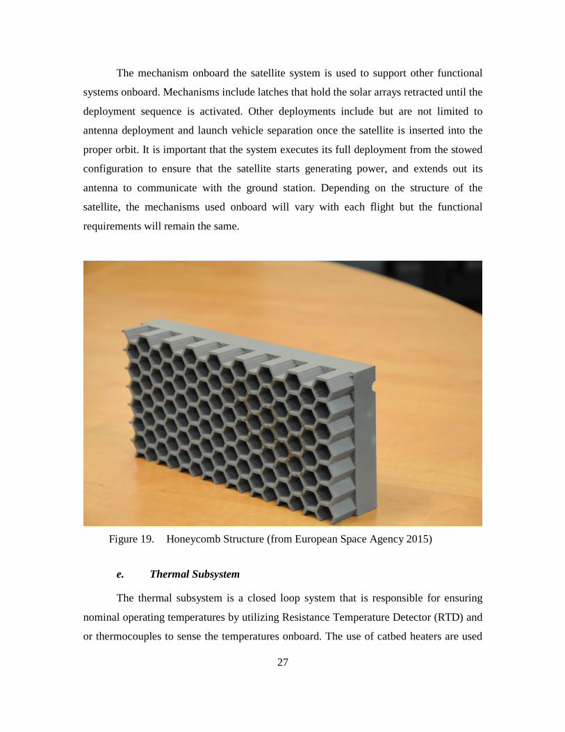
using a light weight honeycomb design, trusses, or modular panels that can be integrated
in multiple sections as shown in Figure 19.
27
The mechanism onboard the satellite system is used to support other functional
systems onboard. Mechanisms include latches that hold the solar arrays retracted until the
deployment sequence is activated. Other deployments include but are not limited to
antenna deployment and launch vehicle separation once the satellite is inserted into the
proper orbit. It is important that the system executes its full deployment from the stowed
configuration to ensure that the satellite starts generating power, and extends out its
antenna to communicate with the ground station. Depending on the structure of the
satellite, the mechanisms used onboard will vary with each flight but the functional
requirements will remain the same.
Figure 19. Honeycomb Structure (from European Space Agency 2015)
e. Thermal Subsystem
The thermal subsystem is a closed loop system that is responsible for ensuring
nominal operating temperatures by utilizing Resistance Temperature Detector (RTD) and
or thermocouples to sense the temperatures onboard. The use of catbed heaters are used

28
in conjunction with Multi-Layer Insulation (MLI) to provide adequate thermal heat to
ensure that critical sensors are operating above the acceptable lower temperature range.
Conversely, radiators and cyrocoolers are utilized to dissipate the heat generated by the
onboard electronics. Figure 20 shows a RTD probe that has a protruding sensor. Figure
21 shows the MLI that typically is applied over critical sensors and electronics.
Figure 20. RTD Probe (from Correge 2015)

29
Figure 21. MLI (from Aerospacefab 2015)
f. Communication Subsystem
The communication subsystem is responsible for receiving and transmitting
encrypted data directly to the ground systems. Space data links that utilize crosslink
antennas to transfer data from one satellite to another is an alternative that can be used if
the system is designed to include this function. An advantage of utilizing the space
crosslink is that commands can still be directed to the space system even if the system is
out of the line of sight of the ground station. Typical uplink and downlink satellite
frequencies are unique such that there is no unintended interference. The data transmitted
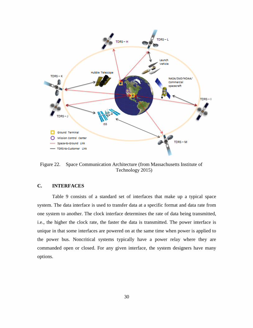
consists of the health and status of the system and valuable payload data. Figure 22
illustrates multiple communication methods that the communication subsystem onboard
can relay inform to and from the ground station.
30
Figure 22. Space Communication Architecture (from Massachusetts Institute of
Technology 2015)
C. INTERFACES
Table 9 consists of a standard set of interfaces that make up a typical space
system. The data interface is used to transfer data at a specific format and data rate from
one system to another. The clock interface determines the rate of data being transmitted,
i.e., the higher the clock rate, the faster the data is transmitted. The power interface is
unique in that some interfaces are powered on at the same time when power is applied to
the power bus. Noncritical systems typically have a power relay where they are
commanded open or closed. For any given interface, the system designers have many
options.

31
Table 9. Satellite Interface Types
Interface Types Functionality Data Provide sensor data or system data Clock Provide a reference clock or system timing Power Provide power Ground Provide a system ground reference or electrical return path
Power Relays Provide a functional on/off switch
Together these interfaces work in unison to connect these highly complex
systems. They work together through highly complex system interfaces that tie each
subsystem together to support the main operation of the satellite, which is to provide the
payload a safe and hospitable environment in which the payload may operate. It is
important to understand that if any one of the subsystems or interfaces experiences a total
system-wide failure, the mission life of the satellite will be significantly degraded or lost.
D. STANDARDIZATION
To fully realize the benefits of standardization of systems, interfaces, and
networks, adoption by all pertinent stakeholders is necessary. Any form of
standardization can be implemented on any physical or nonphysical system or interface.
An example of a standardized interface is the power outlet that interfaces with a
computer, television, fan, cell phone charger, or stereo. If a standard power outlet and
power rating did not exist, manufacturers and the utility providers could potentially
design a system that would require special power converters or electrical plugs that
would require the use of customized manufactured plugs. Such disparity would be of a
great disadvantage for the users.
For the U.S. military, tolerance issues were observed when they procured
replacement items from various suppliers. These issues ultimately affected the supply
chain and the servicing of critical equipment since the parts procured could not be used.
The U.S. military resolved these problems by developing military standards to help
resolve their supplier issues and to ensure the parts they procured met a defined standard.

32
Since then, standards have been widely adopted and led by organizations around the
world as defined in Table 1.
A study on standardization led by the DIN has shown that standardization has
provided short and long term benefits with regards to costs and being more competitive
than those companies that did not participate. Standards have proven to lower production
cost, increase supplier base and cooperation between businesses, reduce R&D cost,
increase overall product safety and reliability, and create positive stimulation for
innovation (Verlag 2008). For the space industry, some progress has been made towards
standardization. Commercial satellite manufacturers have long developed company
standardized satellite buses, whereas the government has recently been more open to
incorporating the use of standardized satellite buses in lieu of designing a system that is
fully optimized.
1. Commercial Standardized Satellite Bus
Commercial standardized busses have existed since the mid-1980s to help
alleviate the cost and risk placed on the stakeholders. System trades such as performance,
cost, risk, weight, and power consumption must be performed prior to selecting a
standardized satellite bus. By utilizing a standardized satellite bus, there is a potential that
there will be some systems with excess capability since the system design is not
customized around the payload to maximize overall system performance. But a
significant advantage to using a standardized satellite bus is if a system is lost due to a
system or launch failure, the satellite manufacturer can replenish the lost capability at a
faster pace. Table 10 lists a subset of commercial standardized satellite busses that is
offered today.

33
Table 10. Commercial Standardized Satellite Bus
Manufacturer Platform Introduction
Payload Mass (Kg)
Power (KW)
References
Loral 1300 1985 5500 - 6000 5 - 25
(Loral 2015)
Lockheed A2100 A 1992 2800 1.5 - 6.7
(Lockheed Martin 2015a)
Lockheed A2100 AX 1994 4700 6 - 12
(Lockheed Martin 2015a)
Lockheed A2100 AX - Land Mobile 1995 5000 6 - 12
(Lockheed Martin 2015a)
Lockheed A2100 AX - High Power 1996 6000 7.5 - 12
(Lockheed Martin 2015a)
Boeing 702HP 1997 5400 - 5900 > 12
(Boeing 2015)
Boeing 702HP GEM 1997 1250 - 1480 8 - 10
(Boeing 2015)
Boeing 702MP 2009 5800 - 6100 6 - 12
(Boeing 2015)
Boeing 702SP 2012 1500 - 2000 3 - 8
(Boeing 2015)
Boeing 502 2014 1000 1.5 (Boeing 2015)
Commercial standardization of the satellite bus is the first step of many to ensure
the rapid replenishment of a lost satellite capability, overall system affordability, and
reducing system risk. But with the current commercial standardized satellite bus designs,
system limitations still persists since these systems are considered proprietary. The next
logical step is to drive standardization to an open platform where these satellite buses
utilize an open architecture framework that utilizes standardized interfaces.
2. Military Efforts on Standardization
Military standards have long existed before the first space systems. The first
round of standards were first introduced to address interoperability, product design and

34
operating requirements, commonality, reliability, total cost of ownership, compatibility
with logistic systems, and other defense related objectives (Defense Acquisition
University 2015). Efforts on behalf of the USG have been conducted through the years to
investigate the effects of standardization on various space systems and space support
systems such as launch vehicles as shown in Table 11.
Table 11. Standardization Efforts Led by the U.S. Government
Efforts Led by the Government Year References Operational Responsive Space 2007 (Operational Responsive Space 2015) Space Universal Modular Architecture 2013 (Collins 2013)
a. Operational Responsive Space
In 2007, Operational Responsive Space (ORS) was created to address the
government’s national security interest in space. The ORS office has implemented a rapid
innovative process known as Modular Open Systems Architecture (MOSA) to achieve a
faster cadence in manufacturing, integration, and launch of a system. The results
achieved thus far have been developing and delivering capabilities to the warfighter in a
compressed timeline, driving down overall cost and development timeline, and being able
to use the latest and innovative technologies (ORS 2015).
b. Space Universal Modular Architecture
Space Universal Modular Architecture (SUMO) is a government led study that
was initiated in 2013 with the goal to reduce the cost of space systems without negatively
impacting system performance, system reliability, operations, and to help the U.S.
industry be more responsive in a growing international space market. The SUMO
approach is being led in collaboration with the Space and Missile Center (SMC), NASA,
and the National Reconnaissance Office (NRO). The study is still in its early phase and
has yet to achieve full commitment from all its industry partners (Collins 2013).

35
Figure 23. SUMO Notional Transition Plan (from Collins 2013)
3. Launch Vehicle Interface Standardization
Launch vehicle providers have to provide a unique launch vehicle to payload
interface that is customized for each mission due to the highly customized nature of the
payload. Since there is no overall governance on how to design the launch vehicle to
payload interface, the space systems manufacturers have free reign to design these
interfaces that best suits their needs without a specific standard to follow. Various
satellite manufacturers may design a system that requires various amounts of data
acquisition signals, launch vehicle separation signals, power lines, and bi-level controls.
This variation results in the development of customized launch vehicles that can only
serve one specific mission. Standardizing the launch vehicle interface would allow for a
more robust launch capability since any available launcher could be used if for any
reason a launch vehicle is grounded due to an hardware issues that were discovered
during system checkouts.

36
4. Path Forward
Now that the space system and interfaces are understood, system engineering
methodologies and principles will be used to inform the modeling and analysis efforts in
the next chapter.

37
III. MODELING AND ANALYSIS
A. SYSTEMS ENGINEERING
The utilization of system engineering principles and processes is integral in
breaking down the thesis investigation into manageable pieces, as shown in Figure 24.
The first step that needed be taken into account was to determine the main objectives of
the research, which was outlined in Chapter I. Throughout Chapter II, the space system
was defined and further decomposed into its subsystems and the different interface types.
The subsequent step of the systems engineering process is to model the system and to
perform a stakeholder analysis. The importance of the stakeholder analysis is to
determine who the interested parties are and to determine their level of involvement with
a standardized space system interface as identified in Table 12.
Figure 24. Systems Engineering Principles (from MITRE 2013)

38
The identified stakeholders each have varying interests with the adoption of a
standardized satellite interface. For the operational users, the concept of operations may
change if newer systems contain newer technology resulting in better information that
can be used by decision makers. In addition, the development and system replenishment
cycle of the system should potentially decrease as technological improvements and
engineering resources shift to address the manufacturability and system resiliency of the
system. As a result of standardization, the entire engineering community and industrial
support base from rocket manufacturers and suppliers will drive overall system
improvements and risk reduction as a means to differentiate their product against one
another.
Table 12. Stakeholders’ Analysis
Stakeholders Involvement
Operational Users
Heavily involved; End users of the data and the system. Need to understand the capabilities and limitations of the system
Satellite Manufacturers Heavily involved; Need to know what to build and how to test the functionality of the system
Rocket Manufacturers Moderately involved; Need to understand the rocket to payload interface
Design Engineers
Heavily involved; Need to understand the interfaces in order to design to the mission specific requirements
Systems Engineers Heavily involved; Chief architects of the system and subsystems. Need to understand limitations in design
Suppliers Moderately involved; Need to supply components and raw materials for the system
Government Offices and Organizations - Domestic and International
Heavily involved; Need to define standards within their respective field

39
Key performance parameters (KPP) are key system attributes determined by the
system architects and engineers that can be quantifiably measured throughout the
development of the system. These parameters are selected early in the system design
phase and are deemed the most critical for the system. If any shortfalls in performances
are identified, it could potentially hinder the capability of the overall mission (Defense
Acquisition University 2015). Table 13 identifies the KPPs that need to be evaluated for
any performance shortfalls when identifying key interfaces for potential standardization.
Table 13. Key Performance Parameters
Key Performance Parameters Example Performance Measure System Mass 3500 Kg
Power Consumption 20 Watt
Data Interface Modular - capable of handling low or high speed
data Minimal error in data transmission Data Integrity 0.0001% error per byte transmitted or received
Figure 25 illustrates the overall systems engineering process from a top level
perspective. Following the V-diagram is the Systems Engineering Management Plan
(SEMP) is generated to govern the life cycle of the system from the design to when the
system is decommissioned. During each step of the process are validation and
verification steps that are designed into the systems engineering process to ensure that the
system being designed is ultimately what the end users wanted.

40
Figure 25. Systems Engineering V Diagram (from Kossiakoff, Sweet, Seymour,
and Biemer 2011)
Figure 26 shows the different types of systems engineering activities and
documents that are generated as part of this detailed process. For the thesis research, the
problem definition was identified in Chapter I. The next step is to develop a model that
outlines the systems functions and physical allocation, which details the system to system
interface interactions.
Figure 26. Systems Engineering Activities and Documents (from Kossiakoff et al.
2011)
41
B. SATELLITE SUBSYSTEM MODELING
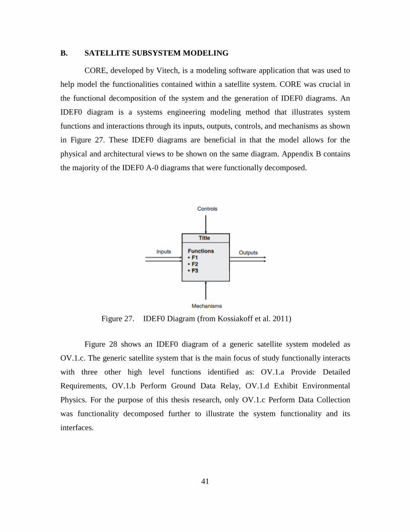
CORE, developed by Vitech, is a modeling software application that was used to
help model the functionalities contained within a satellite system. CORE was crucial in
the functional decomposition of the system and the generation of IDEF0 diagrams. An
IDEF0 diagram is a systems engineering modeling method that illustrates system
functions and interactions through its inputs, outputs, controls, and mechanisms as shown
in Figure 27. These IDEF0 diagrams are beneficial in that the model allows for the
physical and architectural views to be shown on the same diagram. Appendix B contains
the majority of the IDEF0 A-0 diagrams that were functionally decomposed.
Figure 27. IDEF0 Diagram (from Kossiakoff et al. 2011)
Figure 28 shows an IDEF0 diagram of a generic satellite system modeled as
OV.1.c. The generic satellite system that is the main focus of study functionally interacts
with three other high level functions identified as: OV.1.a Provide Detailed
Requirements, OV.1.b Perform Ground Data Relay, OV.1.d Exhibit Environmental
Physics. For the purpose of this thesis research, only OV.1.c Perform Data Collection
was functionality decomposed further to illustrate the system functionality and its
interfaces.

42
Figure 28. IDEF0: Satellite System Context Diagram
Figure 29 further decomposes OV.1.c into its six functional subsystems: Provide
Command and Data Handling, Provide Attitude Control, Provide RF Communication,
Provide Power, Regulate Thermal Environment, and Acquire Payload Data. As described
in Chapter II, each of the subsystems provides a function that is required to keep the
system running. From the defined interfaces, the Command and Data Handling
subsystem is subjected to the largest number of inputs from other subsystems since it is
effectively the command and control node for the entire system. Subsequently, the RF
communication system handles the second most inputs from other subsystems. This is
important to note when starting to identify key interfaces that can be subjected for
standardization efforts.

43
Figure 29. IDEF0: Space System Decomposition

44
1. Command and Data Handling Subsystem Decomposed
In the previous section, the Provide Command and Data Handling function was
identified as having the most system interactions in the entire system, thus making it a
key candidate for interface standardization. Figure 30 functionally decomposes the
Command and Data Handling functional architecture further to extrapolate additional
interface interactions.
From an initial observation, the Provide Command and Data Handling function
utilizes the greatest amount of inputs and outputs. It is important to note that the
Command and Data Handling subsystem processes all onboard subsystem data, ground
commands, and runs flight software. Given the amount of data the system needs to
process, it is not surprising that a majority of the functions are heavily utilized. Such
functions include memory storage, timing, spacecraft control processor computation,
command authentication, flight software, fault management, and telemetry conditioning.
All of these functions within this subsystem will need to be further examined, and should
be considered top candidates for standardization efforts.

45
Figure 30. IDEF0: Command and Data Handling Subsystem

46
a. Command Authentication
Figure 31 shows the command authentication function that is decomposed within
the Command and Data Handling subsystem. The Command Authentication function
validates all decrypted commands it receives from the RF communication subsystem. It
ensures that the commands it receives is properly formatted (headers, word length,
command count). Once command authentication is confirmed, the data is then
deconstructed further to extract the commands, which is then forwarded and executed by
various onboard systems.
Figure 31. IDEF0: Command Authentication
The Command Authentication function was further decomposed into multiple
IDEF0 A-0 diagrams to get a better understanding of the system to system interfaces.

47
There are three key inputs to the Sync Word Frame Lock function as illustrated in Figure
32. It is important to note that two of the three inputs are associated with data interfaces
and the remaining is associated with a power interface. The mechanism that enables the
Frame Sync function is a specified frame sync word that is defined in a hexadecimal
format. The output of the sync word frame lock function sends properly framed and
formatted data for further extraction by flight software and other onboard systems.
Figure 32. IDEF0 A-0: Sync Word Frame Lock
Figure 33 shows the functionality of how commands are extracted from the frame
sync data by means of a frame parser. The extracted commands are then routed to flight
software for processing and then eventually transferred by means of the data bus to its
intended onboard destination. The interfaces between both functions are fairly identical
with the exception that the amount of data inputs increased by one.

48
Figure 33. IDEF0 A-0: Unparse Commands
Under further examination of the Command Authentication interfaces, the frame
parser and word sync should relatively be easy to design and conform to a standardized
interface. The main problem is ensuring that there is an adequate amount of data lines and
designing the hardware to account for varying data rates. Any deviations to the frame
parser and word sync can be modified easily with a simple change to the firmware.
b. System Timing
Figure 34 decomposes the System Timing function within the Command and Data
Handling subsystem. The System Timing function provides a reference clock for the
entire onboard systems to use. The purpose of the reference clock is to ensure software
and hardware functional system activities are to be performed at set clock cycles and
system times. The reference clock is synced to the GPS timing solution it receives from
GPS satellites. Once that process is complete, it is further propagated by means of a
crystal oscillator onboard. The amount of re-synchronization required onboard is
dependent on the accuracy of the crystal oscillator and its drift rate.

49
Figure 34. IDEF0: Provide System Timing
From a detailed observation of the system timing interface, the timing signal is
broadcasted in one direction to all onboard systems. This is a relatively simple interface
to design and should be clustered with the data interface since all electrical systems and
components need to operate on the same system time. The benefits of clustering the data
interface with the timing interface together will minimize the amount of hardware
connection points and drive down overall system weight.
c. Fault Management
Figure 35 illustrates the Perform Fault Management function contained within the
Perform C&DH function. The Fault Management system is one of the most critical
software and hardware functional components onboard. It monitors the health of the
entire space system and triggers predefined command sequences autonomously in the

50
event of a software issue, watchdog timer fault, hardware failure, loss of ground
commanding, and a subsequent power surge or power loss. Specific command sequences
stored onboard are activated for certain fault conditions, which automatically commands
the satellite into a safe state for further troubleshooting by ground support engineers. The
system is typically triple redundant where a voting schema is performed to ensure a true
fault is identified.
Figure 35. IDEF0: Perform Fault Management
Figure 36 illustrates the system function of how a stored command sequence is
activated when the fault management system detects a system fault. The flight software
algorithm activates a pre-defined command sequence for the specific fault, which
commands the satellite to enter a safe defined state to allow ground controllers to review
and rectify the fault condition.
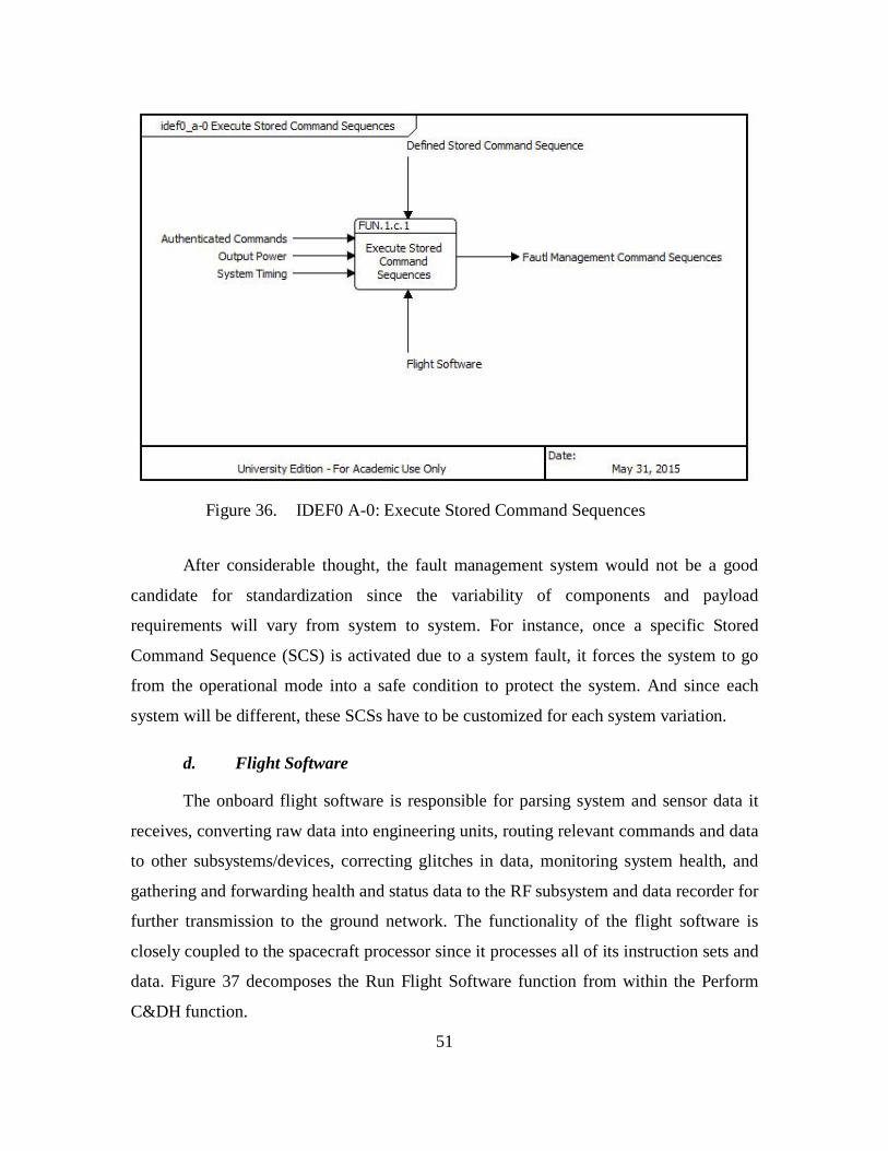
51
Figure 36. IDEF0 A-0: Execute Stored Command Sequences
After considerable thought, the fault management system would not be a good
candidate for standardization since the variability of components and payload
requirements will vary from system to system. For instance, once a specific Stored
Command Sequence (SCS) is activated due to a system fault, it forces the system to go
from the operational mode into a safe condition to protect the system. And since each
system will be different, these SCSs have to be customized for each system variation.
d. Flight Software
The onboard flight software is responsible for parsing system and sensor data it
receives, converting raw data into engineering units, routing relevant commands and data
to other subsystems/devices, correcting glitches in data, monitoring system health, and
gathering and forwarding health and status data to the RF subsystem and data recorder for
further transmission to the ground network. The functionality of the flight software is
closely coupled to the spacecraft processor since it processes all of its instruction sets and
data. Figure 37 decomposes the Run Flight Software function from within the Perform
C&DH function.

52
Figure 37. IDEF0: Run Flight Software
Flight software is unique in terms of interfaces since it has a physical interface
and a nonphysical interface known as the software interface. For the purpose of this
thesis research, the software interface was not thoroughly investigated for
standardization. The standardization of the physical interfaces is covered within the
Spacecraft Control Processor, Memory Storage, and Telemetry Conditioning interfaces.
e. Manage Internal/External Data Bus
The internal data bus resides within the spacecraft processor and possesses a vital
system function of transferring data between the processor, and processor memory for
near real time data computation. The external data bus is used to connect the Command
and Data Handling subsystem to other onboard subsystems. This allows for high data rate
transmissions between various onboard systems as illustrated in Figure 38. Typically
space systems utilize MIL-STD-1553 or SpaceWire for their external data bus due to its
robustness, design flexibility, and data rate.

53
Figure 38. IDEF0: Manage Internal/External Data Bus
In order to standardize the data buses, the internal and external data bus must be
examined independently. Since the internal data bus typically resides within the
spacecraft processor or on the printed board it is attached to, standardizing this interface
will not be feasible since the system is already self-contained. As for the external data
bus, understanding the data transfer rate required will determine what type of data bus
will be utilized. SpareWire uses newer protocols, which provide a significantly faster data
transfer rate as compared to MIL-STD-1553. Other differences include the physical
interface, for instance MIL-STD-1553 utilizes a twinax cable connection whereas
SpaceWire utilizes a micro-miniature D-type connector (Parkes 2012). Based on the
differences in the physical connector types, two different data interface standards will
need to be developed to accommodate the lower and higher rate data bus.

54
f. Perform Memory Storage
Figure 39 decomposes the Perform Memory Storage function onboard the
satellite. The system recorder is used to capture data from the payload and the spacecraft.
Payload data and spacecraft data is collected when the ground station is out of line of
sight and downlinked whenever possible. The onboard memory storage is also utilized to
capture system data during a system fault and downlinked for processing later. The data
stored onboard is vital to ensure that all relevant payload mission data is not lost when the
ground station is out of sight.
Figure 39. IDEF0: Perform Memory Storage
The memory storage onboard is not too different from any of the other data
interfaces that have been examined thus far. The only difference is that the same
processed data that is relayed to the RF subsystem is also relayed to the recorder to be
recorded when the ground station is out of line of sight. Standardizing this interface
makes perfect sense since it shares a similar data interface as previously examined.

55
g. Perform Spacecraft Control Processor Computation
The spacecraft control processor is closely coupled with flight software to run its
application and to perform calculations as requested by flight software as illustrated in
Figure 40. The processed data is utilized by flight software to ensure sensor and system
health is within its allowed alarmed limits. It also processes attitude data and will adjust
the orbit of the spacecraft if required. Performance and power limitations do exist for the
spacecraft, such limitations include internal memory size, processor speed, and power
consumption rate.
Figure 40. IDEF0: Perform Spacecraft Control Processor Computation
After careful examination of the spacecraft processor in conjunction with flight
software, it does make sense to standardize the data interface since it processes all
pertinent data that it receives from all other onboard systems. The major difference from

56
the other data interfaces is that the spacecraft processor will have to allocate a data
interface for every system component with which it interacts.
h. Provide Telemetry Conditioning
The telemetry format table allocates specific data to fill each frame of data as
specified within the flight software as illustrated in Figure 41. Data words that include the
vehicle health are segmented into different frames, and are dependent on the frequency
the ground operators would like to monitor the data. If a specific telemetered data is
required to be read at a high frequency, the data would most likely appear in every frame
of downlinked data.
Figure 41. IDEF0: Provide Telemetry Conditioning
The telemetry format table is a software function where the data is received and
processed by flight software and then transmitted to the RF subsystem to downlink to the
ground. Since the format tables are configurable by editing the configuration files, there

57
is no real need to develop any form of standardization at this time since it is currently a
software driven function.
2. Attitude Control Subsystem Decomposed
The attitude control system is responsible for keeping the satellite stable and in a
desired orbit with the utilization of its suite of components and sensors that have the
capability to provide thrust, angular rotation, and stabilization to ensure calibrated
pointing and steering. It is also responsible for determining its location by means of GPS
receivers, star trackers, and sun/earth sensors, and if for any reason the satellite is in the
incorrect orbit, orbit adjustments will be made by firing onboard thrusters. Figure 42
illustrates the functional architecture of the attitude control system.
After careful examination of the attitude sensing interfaces illustrated in Figure 43
and Figure 44, it would be a difficult task to standardize any interfaces based on multiple
unknown variables such as the systems center of gravity, system weight, and structural
shape. Understanding the system weight and center of gravity is important because the
size and placement of the gyroscope and resolvers will ultimately determine what the
interface will look like. Typically larger systems will require larger components, which in
turn will require additional data and power interfaces to drive the mechanical
components. Fixed systems that provide no movement such as star trackers, sun earth
sensor, and global positioning receivers can be standardized since the amount of data and
power interfaces is known will not be adversely affected by system mass or the systems
center of gravity.

58
Figure 42. IDEF0: Provide Attitude Control
Figure 43. IDEF0: Actuate Attitude Control System

59
Figure 44. IDEF0: Attitude Sensing
3. RF Communication Subsystem Decomposed
The RF communication subsystem handles a critical function onboard the satellite
as shown in Figure 45. It provides the vital communication link between the satellite and
the ground users. Ground users utilize ground stations that are strategically placed around
the world to uplink and downlink data to and from the satellite. Conversely, on the other
end, the satellite utilizes the dual redundant Space Ground Link System (SGLS) system
to downlink encrypted vehicle health and status and payload mission data. The uplink and
downlink frequencies must operate on different frequencies and from other space based
or terrestrial systems to avoid any system interference.
Standardizing the SGLS interface will be quite complex due to a multitude of
factors that surrounds the cryptographic interface and the uplink and downlink

60
frequencies as shown in Figure 46. Since the cryptographic functionality is housed within
the SGLS, any form of standardization whether it be software or hardware may cause
system vulnerabilities that the users may not be comfortable with. In addition to the
system vulnerabilities, the uplink and downlink frequencies have to be designed to
operate on different frequencies, which will require engineering time to modify each
SGLS to accommodate the variations in operating frequencies. With all the added
complications, the SGLS interface would not be a good candidate for interface
standardization.
Figure 45. IDEF0: Provide RF Communication

61
Figure 46. IDEF0: Space Ground Link Systems
4. Electrical Power Subsystem Decomposed
The EPS subsystem is responsible for generating power from its solar arrays by
efficiently rotating the solar arrays to track the movement of the sun as shown in Figure
47. The rotation of the solar panels will ensure that the system is used effectively to
convert the sun’s energy into useable power for onboard systems. In addition to
generating power, the power subsystem is responsible for regulating the power from the
solar arrays to the entire system to ensure the right operating voltage is being supplied. At
any instance, if the power loads exceeds the allowable limit, emergency load shedding of
noncritical systems will occur. Any excessive power load will trigger an alarm and will
have to be rectified by ground users.

62
Figure 47. IDEF0: Power Subsystem
a. Generate Power
Power generation is generated onboard by converting sunlight into electrical
power by means of the solar arrays onboard as shown in Figure 48. Sun tracking
algorithms will rotate the Solar Array Drive Assembly (SADA) to maximize the amount
of energy being generated. The size of the battery and solar array is determined by the
amount of power required at BOL and EOL.

63
Figure 48. IDEF0: Generate Power
The power generation system is a good candidate for standardization because the
solar arrays that are used in space are designed to stringent requirements due to its
operating environment. The performance efficiencies in electricity generation and solar
panel size will determine the amount of panels required and the size of the SADA. Since
this system is self-contained, designing a standardized interface will be relatively easy.
b. Provide Power
The Electrical Power system is responsible for providing power to all components
onboard as shown in Figure 49. Some pre-determined systems or components are
hotwired meaning that they are turned on once power is applied to the power bus. Other
systems deemed not so essential have independent power relays that can latch open to
turn off power or closed to provide power. Having this ability means that during off

64
nominal system conditions, power load shedding can be performed to conserve energy or
to perform troubleshooting.
Figure 49. IDEF0: Provide Power
Due to the abundance and variations in power relays, standardizing the power
relay interfaces will provide a huge payoff since power is required on all electrical
interfaces. Designing the C&DH interface with the power interface in mind could
potentially address all interfacing needs for these two subsystems.
c. Charge Batteries
One of the key functions of the electrical power system is charging the batteries
when excess power is generated as shown in Figure 50. The batteries provide power to
the system when the solar arrays cannot provide the sufficient power to keep the system
operational. The batteries capability to store power will diminish as a function of time

65
and charge and discharge cycles. The health of the battery is a huge factor in determining
the life of the system.
Figure 50. IDEF0: Charge Batteries
Depending on the BOL and EOL requirement, it could potentially be too
complicated to standardize the battery interface. Systems that consume more energy will
require more battery cells that can store the necessary power to keep the system
operating. The amount of battery cells required will affect the size and number of
batteries required thus increasing the amount of interfaces required. With the unknown
BOL and EOL requirement, it is not recommended to standardize this interface.
d. Regulate Power
Regulating the power to ensure the proper bus voltage is being applied to all
electrical components on the power bus is a critical function as shown in Figure 51. Any
dips below the allowable operating voltage can cause the electrical system to behave

66
erratically. Glitches and errant data may be transmitted, which will result in multiple
system faults where ground intervention is required. Excessive voltage spikes can
potentially damage circuits thus reducing the on-orbit life of the system.
Figure 51. IDEF0: Regulate System Power
After careful examination of this system interface, standardizing the power
regulator interface does not make sense since the power regulator interface is self-
contained within the power subsystem. The amount of time that would be required to re-
design this interface is relatively low and does not offer a tremendous payoff if it were to
be standardized.
5. Thermal Subsystem Decomposed
Regulating the thermal environments on the spacecraft is a pertinent function that
is required to maintain the operating temperatures of the electronics onboard. The thermal
system must be able to sense temperatures reliably so that the system can appropriately

67
dissipate heat and generate heat as needed as shown in Figure 52. Certain sensors and
equipment onboard may require cryogenic operating temperatures in order to function
properly otherwise erroneous data is generated as a result of temperature fluctuations.
Standardizing the thermal interface subsystem will not be an easy task due to a multitude
of factors such as the uncertainty in amount of electronics onboard, orbit, and structural
size. A closer look into each functional interface will need to be examined before a final
determination can be made.
Figure 52. IDEF0: Regulate Thermal Environment Subsystem
a. Provide Heat
Figure 53 illustrates how the thermal subsystem provides heat to onboard critical
components. Catbed heaters which are strategically placed throughout the onboard
systems generate the necessary heat to ensure that key electronics operate within their

68
desired temperature limits. Flight software commands the catbed heaters on and off when
the temperature is at the designated lower or upper limit. The catbed heaters operate on
electricity generated by solar power such that an alternate source of energy is not
required. MLI is another source of retaining the heat onboard. They serve the same
function as insulation within the dry walls in houses.
Figure 53. IDEF0: Provide Heat
Heat generation is provided by two methods, catbed heaters and MLI.
Standardizing the catbed heater interface is a relatively easy task and should be
investigated since the interface is not complex. Alternatively, since MLI is a mechanical
component, there is no real need to standardize this component since it can be easily
molded to conform to any mechanical interface.

69
b. Sense Temperatures
RTDs and thermocouples are used throughout the electronics suite and within the
structure of the satellite to determine the temperatures onboard the satellite system as
shown in Figure 54. Sensing the temperatures is a critical component in ensuring that the
system is operating as planned. Thermal variance in operating temperatures is usually
recorded and monitored by ground engineers to assess the health of the components or
subsystem.
Figure 54. IDEF0: Sense Temperatures
The standardizing of RTDs and thermocouples is a relatively easy task as long as
the temperature range of the sensor covers the range as experienced by the space system.
The only issue with RTDs and thermocouples would be the placement within the
component housing and structure. The thermal environments behave differently based on
the amount of electronic board and placement of heat generating semiconductors.

70
Additional analysis is required to determine if there will be any benefit in standardizing
this interface.
c. Dissipate Heat
It is important that the thermal subsystem is capable of releasing heat generated
from electronics, the charging of the spacecraft batteries, and through thermal absorbance
from the sun. The utilization of radiators, cryocoolers, and MLI help dissipate heat within
key components and subsystem as illustrated in Figure 55. In the event that the
temperature within the system to nearing its absolute upper limit, flight software will
automatically turn off noncritical spacecraft components thus reducing the amount of
heat being generated and allowing the system to dissipate the trapped heat.
Figure 55. IDEF0: Dissipate Heat
Standardizing the cryocoolers and radiator interface will not be an easy task to
complete due to the amount of uncertainties described earlier. Given how much thermal

71
variations that can occur within an unknown volume, there is no easy way to determine
the size of the cryocoolers and radiator without completing any thermal analysis. Thus, it
is not advantageous to pursue any standardization efforts on this interface at this time.
6. Payload Subsystem Decomposed
Figure 56 shows a sample payload function to capture IR from a typical earth
observation satellite. The complexity of the payload is dependent on the complexity of its
mission objectives. Much like the satellite systems, the payload has its independent
processor, memory storage, and a means to communicate data to the ground if necessary.
Power, attitude control and determination, and communication are provided by the
satellite bus. This thesis research did not intend to address the standardization of any of
the payload interfaces.
Figure 56. IDEF0: Acquire Payload Data Subsystem

72
THIS PAGE INTENTIONALLY LEFT BLANK

73
IV. CONCLUSION
A. RESEARCH QUESTION EVALUATION
Benefits that stem from a standardized interface includes a technically competent
work force with experience in dealing with a standardized interface as opposed to
learning a new interface and all the problems associated with a new design, thus allowing
management to reallocate resources as required. Other short- and long-term benefits with
regards to costs and being more competitive than those companies that did not
participate. In addition, standardization has proven to lower production cost and research
and development (R&D) cost, increase supplier base and cooperation between
businesses, increase overall product safety and reliability, and create positive stimulation
for innovation (Verlag 2008). Another significant advantage of standardization is the
rapid replenishment capability of a lost capability if for any reason the system is lost due
to a launch failure or onboard failure.
In Chapter I, the objectives and the primary research question were identified.
Chapter II provided the fundamental background information on the system, subsystems,
breakdown of system interfaces, and military and commercial industries attempt at
standardization. Although significant progress was made towards standardization by
commercial companies, the system architectures and interfaces utilized were still
proprietary. Chapter III modeled a satellite system using IDEF0 diagrams that illustrated
the functional system components and their interfaces. Detailed functional analysis was
performed on each system interface by means of IDEF0 diagrams to understand the
intricate interactions and system behavior. In this section, the primary research question
is evaluated after undergoing extensive functional analysis and modeling.
The following thesis research questions can now be addressed: Can the
implementation of standardized interfaces on space systems provide any added benefits?
If so, what added benefits do they provide to the consumer or manufacturer? Do they
save overall system cost? Schedule? Do they provide a rapid replenishment capability
when a system capability is lost? What are the interfaces that can be standardized?

74
After performing a functional analysis of the system interfaces by means of
IDEF0, the resulting conclusion is that the implementation of standardization can yield
varying degrees of benefits for all stakeholders. Before going into detail of the benefits of
interface standardization, it is important to understand the system interfaces that are
recommended for standardization. Early on, it was realized that not all interfaces within
each subsystem can be standardized, and that any system interfaces that required the
development of customized solutions have been omitted from any standardized interface
considerations. The biggest return on investment in terms of interface standardization
would come from the C&DH and Electrical Power subsystem, since each component
onboard will require at a minimum a single data and power interface. Table 14 identifies
in greater detail the interfaces recommended for standardization. If these
recommendations are pursued, this will lead to the foundational development of a
standardized interface specification.
1. Standardization Conclusion
In the past two decades, the development of key interface standards such as USB,
IEEE 1394, WiFi, and power have been instrumental in the development of new
technology. International standard organizations along with the commercial industry have
been keen in ensuring that new standards are developed to account for new technology.
Today’s space systems have yet to undergo any forms of standardization that is
widely accepted by all stakeholders. But there is a shift within the space industry to
develop an affordable and resilient system. Government agencies have conducted studies
which indicated modular and open architectures can achieve cost reduction goals, along
with the ability to manufacturer and deliver system capabilities in a compressed timeline.
If any progression is made towards interface standardization for space systems, it will
benefit most stakeholders if a conclusion can be drawn upon the successes of consumer
standards.
Listed below in bullet form summarizes the main findings from the IDEF0
interface analysis.

75
• Standardizing the C&DH data interfaces will provide the biggest return on
investment since the C&DH subsystem interfaces with each onboard
system.
• Incorporation of the power and timing interface along with the data
interface will minimize the amount of connections, thus reducing overall
system mass.
• Any interfaces that require a significant amount of analysis or NRE hours
is not a good candidate for standardization. Such interfaces include the
fault management interface, SGLS system, and some aspects of the
thermal and attitude control system.
• The passive thermal interfaces can be standardized such as catbed heaters
and RTD probes. The active components such as radiators and cryocoolers
will require thermal analysis to determine the ultimate size and its overall
effectivity.
• In summary, here is a list of the interfaces that should be considered for
standardization:
Table 14. Interfaces Recommended for Standardization
Subsystem System Function Recommendation
Command and Data Handling
Command Authentication - Sync Word Frame Lock
Recommended for Interface standardization
Command Authentication - Unparse Commands
Recommended for Interface standardization
System Timing Recommended for interface standardization
Fault Management - Execute Stored Command Sequences
Not recommended for interface standardization; Too much variability between systems;
Fault Management - Monitor System Health
Not recommended for interface standardization; Too much variability between systems;

76
Subsystem System Function Recommendation Manage Internal/External Data Bus
Recommended for interface standardization
Memory Storage Recommended for interface standardization
Spacecraft Control Processor
Recommended for interface standardization
Telemetry Conditioning Not required; software driven function
Attitude Control Attitude Control
Not recommended for interface standardization; Too much variability with system components, which will require engineering evaluation to determine size and weight of thrusters, torque rods, and resolvers
Attitude Sensing Recommended for Interface standardization
RF Communication
Space Ground Link System
Not recommended for interface standardization; Changes in encryption protocols and operating frequencies will require unique interfaces since it will vary from mission to mission.
Electrical Power
Generate Power Recommended for Interface standardization
Provide Power Recommended for Interface standardization
Charge Batteries
Not recommended for interface standardization; The battery size will vary depending on the mission profile. Additional batteries could potentially require customized interfaces to tie all batteries to the power bus
Thermal Provide Heat
Recommended for Interface standardization; MLI does not need any interface work since it is a mechanical component

77
Subsystem System Function Recommendation
Sense Temperature
Recommended for Interface standardization; Additional analysis will need to be required to determine placement of RTD’s and thermocouples
Dissipate Heat
Not recommended for interface standardization; Thermal variances will vary mission to mission. Analysis will need to be conducted to determine size of radiators.
B. FURTHER WORK AND RESEARCH
This thesis investigation only addressed the top level functional breakdown of a
standardized satellite system. Additional refinement of the model would provide added
insight into the system behavior that has not been characterized as part of this work.
Areas of refinement include modeling the payload subsystem, ground station, and user
interfaces. In addition, the functional architecture developed can be tested against
formally specified architecture modeling heuristics. Listed below are additional research
questions that can be studied to further understand the consequences of implementing a
standardized interface on satellites.
1. Further Research Areas
• Perform a cost benefit analysis to determine the overall cost savings if a
standardized interface was implemented on a single satellite versus a
constellation.
• Are standardized systems more prone to security related issues? If so, how
can standardized interfaces be designed to mitigate any security concerns?
• With the implementation of standardized interfaces on space systems,
could that eventually lead to on-orbit serviceability? If so, what systems
can be serviced and at what cost?

78
THIS PAGE INTENTIONALLY LEFT BLANK

79
APPENDIX A. TRL READINESS LEVEL (FROM NASA 2015D)
TRL 1 Basic principles observed and reported: Transition from scientific research to
applied research. Essential characteristics and behaviors of systems and architectures.
Descriptive tools are mathematical formulations or algorithms.
TRL 2 Technology concept and/or application formulated: Applied research. Theory and
scientific principles are focused on specific application area to define the concept.
Characteristics of the application are described. Analytical tools are developed for
simulation or analysis of the application.
TRL 3 Analytical and experimental critical function and/or characteristic proof-of
concept: Proof of concept validation. Active Research and Development (R&D) is
initiated with analytical and laboratory studies. Demonstration of technical feasibility
using breadboard or brassboard implementations that are exercised with representative
data.
TRL 4 Component/subsystem validation in laboratory environment: Standalone
prototyping implementation and test. Integration of technology elements. Experiments
with full-scale problems or data sets.
TRL 5 System/subsystem/component validation in relevant environment: Thorough
testing of prototyping in representative environment. Basic technology elements
integrated with reasonably realistic supporting elements. Prototyping implementations
conform to target environment and interfaces.
TRL 6 System/subsystem model or prototyping demonstration in a relevant end-to-end
environment (ground or space): Prototyping implementations on full-scale realistic
problems. Partially integrated with existing systems. Limited documentation available.
Engineering feasibility fully demonstrated in actual system application.
TRL 7 System prototyping demonstration in an operational environment (ground or
space): System prototyping demonstration in operational environment. System is at or
near scale of the operational system, with most functions available for demonstration and
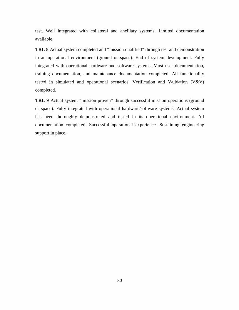
80
test. Well integrated with collateral and ancillary systems. Limited documentation
available.
TRL 8 Actual system completed and “mission qualified” through test and demonstration
in an operational environment (ground or space): End of system development. Fully
integrated with operational hardware and software systems. Most user documentation,
training documentation, and maintenance documentation completed. All functionality
tested in simulated and operational scenarios. Verification and Validation (V&V)
completed.
TRL 9 Actual system “mission proven” through successful mission operations (ground
or space): Fully integrated with operational hardware/software systems. Actual system
has been thoroughly demonstrated and tested in its operational environment. All
documentation completed. Successful operational experience. Sustaining engineering
support in place.

81
APPENDIX B. IDEF0 A-0 DIAGRAMS
Command and Data Handling IDEF0 A-0 Subsystem Functions:
Figure 57. IDEF0 A-0: Generate System Timing

82
Figure 58. IDEF0 A-0: Update System Timing from GPS
Figure 59. IDEF0 A-0: Read Hardware Data

83
Figure 60. IDEF0 A-0: Generate and Format Telemetry
Figure 61. IDEF0 A-0: Executes Ground Commands

84
Figure 62. IDEF0 A-0: CRC Error Correction
Figure 63. IDEF0 A-0: Monitors System Health

85
Figure 64. IDEF0 A-0: Format System Data
Figure 65. IDEF0 A-0: Transmit/Receive High Speed Data Rates

86
Figure 66. IDEF0 A-0: Run Instructions from FSW
Figure 67. IDEF0 A-0: Perform Logic Calculations

87
RF Communication IDEF0 A-0 Subsystem Functions:
Figure 68. IDEF0 A-0: Transmit and Receive Data
Figure 69. IDEF0 A-0: Decrypt Received Data
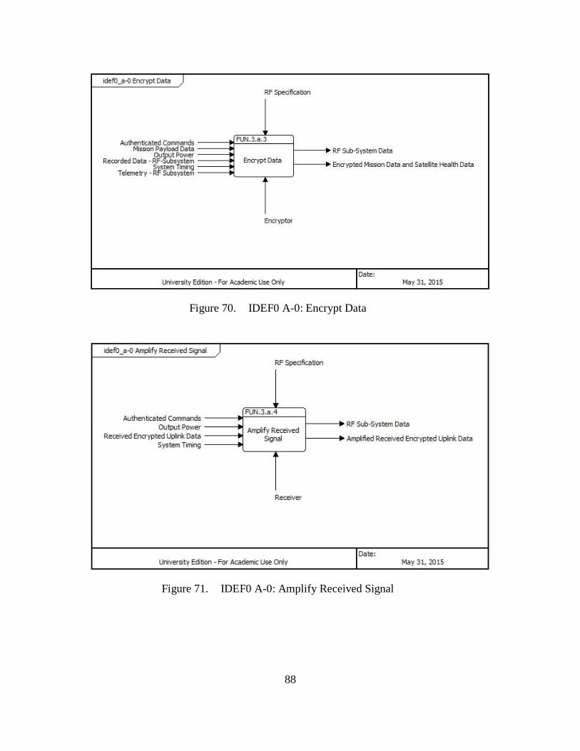
88
Figure 70. IDEF0 A-0: Encrypt Data
Figure 71. IDEF0 A-0: Amplify Received Signal

89
Attitude Control IDEF0 A-0 Subsystem Functions:
Figure 72. IDEF0 A-0: Provide Rotation
Figure 73. IDEF0 A-0: Provide Angular Rotation

90
Figure 74. IDEF0 A-0: Provide Thrust
Figure 75. IDEF0 A-0: Provide Stabilization

91
Figure 76. IDEF0 A-0: Maintain Orientation
Figure 77. IDEF0 A-0: Determine Magnetic Field

92
Figure 78. IDEF0 A-0: Measures Degrees of Freedom
Figure 79. IDEF0 A-0: Determine Direction of the Sun and Earth

93
Figure 80. IDEF0 A-0: Provide Position
Figure 81. IDEF0 A-0: Track Stars
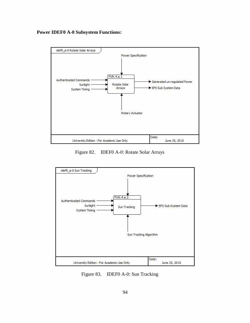
94
Power IDEF0 A-0 Subsystem Functions:
Figure 82. IDEF0 A-0: Rotate Solar Arrays
Figure 83. IDEF0 A-0: Sun Tracking

95
LIST OF REFERENCES
Aerospace. 2015. Into Orbit – A Brief History of Space Exploration. Accessed July 25. http://www.aerospace.org/education/inspiring-the-next-generation/space-primer/a-brief-history-of-space-exploration/
Aerospacefab. 2015. Multilayer Insulation. Accessed July 18. http://www.aerospacefab.com/products.htm.
AIA. 2012. Competing for Space. Accessed August 2, 2015. http://www.aia-aerospace.org/assets/CompetingForSpaceReport.pdf.
AIM. 2010. MIL-STD-1553 Tutorial. Accessed July 19, 2015. https://www.aim-online.com/pdf/OVW1553.PDF.
American Society of Mechanical Engineers. 2015. Engineering History Accessed July 25. https://www.asme.org/about-asme/engineering-history.
American National Standards Institute. 2015. ANSI: Historical Overview. Accessed July 25. http://www.ansi.org/about_ansi/introduction/history.aspx?menuid=1.
BAE Systems. 2015a. Processors. Accessed July 25. http://www.baesystems.com/download/BAES_161071/processors.
———. 2015b. RAD750 Radiationed Hardened PowerPC Microprocessors. Accessed July 25. http://www.baesystems.com/download/BAES_052281/Space-Products--RAD750-component.
———. 2015c. RAD750 6U CompactPCI Single-board Computer. Accessed July 25. http://www.baesystems.com/download/BAES_052280/Space-Products--RAD750-6U-cPCI.
———. 2015d. RAD6000 Space Computers. Accessed July 25. http://montcs.bloomu.edu/~bobmon/PDFs/RAD6000_Space_Computers.pdf.
Ball Aerospace. 2015. Star Trackers. Accessed July 22. http://www.ballaerospace.com/page.jsp?page=104.
Boeing. 2015. Boeing Satellites. Accessed July 25. http://www.boeing.com/space/boeing-satellite-family/.
Borky, J.M. and B. Singaraju. 1995. “Technology and Strategies for Effective Spacecraft Avionics Standardization.” AIAA 95–3714.

96
Broad, William J., 1990. Panel Finds Error by Manufacturer of Space Telescope. Accessed August 19, 2015. http://www.nytimes.com/1990/08/10/us/panel-finds-error-by-manufacturer-of-space-telescope.html.
Collins, Bernie. 2013. Space Universial Modular Architecture (SUMO) Setting the Environment for Industry-Consensus Standards. Accessed July 25. http://www.goddard-contractors-association.org/presentations/SUMO%20for%20NASA%20GCA%20130918.pptx.
Consultative Committee for Space Data Systems. 2015. About CCSDS. Accessed July 25. http://public.ccsds.org/about/default.aspx.
Correge. 2015. Ambient Temperature RTD. Accessed July 18. http://www.correge.fr/rtd-sensor-head-type.html.
Defense Acquisition University. 2015. Key Performance Parameters. Accessed July 21. https://dap.dau.mil/acquipedia/Pages/ArticleDetails.aspx?aid=7de557a6-2408-4092-8171-23a82d2c16d6.
Dubos, G., Saleh, J., and R. Braun. 2007. “Technology Readiness Level, Schedule Risk and Slippages in Spacecraft Design: Data Analysis and Modeling” AIAA 2007–6020.
Encyclopædia Britannica Online. 2015. Hubble Space Telescope (HST). Accessed July 18. http://www.britannica.com/topic/Hubble-Space-Telescope.
European Space Agency. 1970. OBCDH-Architecture. Accessed July 22, 2015. http://www.esa.int/spaceinimages/Images/2011/10/OBCDH-Architecture.
———. 2015. Rapid Prototype of Honeycomb Structure. Accessed July 18. http://www.esa.int/spaceinimages/Images/2014/03/Rapid_prototype_of_honeycomb_structure.
Futron. 2002. Space Transportation Costs: Trends in Price Per Pound to Orbit 1990 – 2000. Accessed August 2, 2015. http://www.futron.com/upload/wysiwyg/Resources/Whitepapers/Space_Transportation_Costs_Trends_0902.pdf.
GAO. 2015. Space Acquisitions – Space Based Infared Systems Could Benefit from Technology Insertion Planning. Accessed August 2. http://www.gao.gov/assets/670/669454.pdf.
GPS. 2015. Global Positioning System Constellation Replenishment. Accessed August 2. http://www.gps.gov/congress/reports/2015/2015-02-AF-report-GPS-constellation-replenishment.pdf.

97
Holguin M. and M. Labbee. 1988. “Launch Vehicle to Payload Interface Standardization: The Quest for a Low Cost Launch System” AIAA 88–0165.
Institute of Electrical and Electronics Engineers. 2015. History of IEEE. Accessed July 25. https://www.ieee.org/about/ieee_history.html.
Intel. 2015. Microprocess Quick Reference Guide. Accessed July 25. http://www.intel.com/pressroom/kits/quickreffam.htm#i486.
Intelsat. 2015. Services: Satellite Procurement. Accessed August 2. http://www.intelsat.com/services/satellite-related/satellite-procurement/.
International Council on Systems Engineering. 2015. About INCOSE. Accessed July 25. http://www.incose.org/about.
International Space Exploration Coordination Group. 2013. Benefits Stemming from Space Exploration. Accessed July 25, 2015. http://www.spazioallescuole.it/files/ISECG_Benefit_White_Paper_September_2013_0.pdf.
International Organization for Standardization. 2015. The ISO Story. Acessed July 25. http://www.iso.org/iso/home/about/the_iso_story.htm.
Jet Propulsion Labatory. 2000. Report on the Loss of the Mars Polar Lander and Deep Space 2 Missions. Accessed July 25, 2015. ftp://ftp.hq.nasa.gov/pub/pao/reports/2000/2000_mpl_report_1.pdf.
———. 2015. Radiation Effects on Satellites – A JPL Perspective. Accessed August 2. http://www.swpc.noaa.gov/sites/default/files/images/u33/Radiation_Effects_on_Satelliters-A_JPL_Perspective.pdf.
Kossiakoff, A., Sweet, W., Seymour, S., Biemer, S., 2011. Systems Engineering Principles and Practice. New Jersey. John Wiley & Sons, Inc.
Lafleur, C., 2015. The Number of Satellites Launched Each Year. Accessed July 25. http://claudelafleur.qc.ca/Spacecrafts-index.html#Table-1.
Lockheed Martin. 2015a.A2100. Accessed July 25. http://www.lockheedmartin.com/content/dam/lockheed/data/space/documents/a2100/A2100brochure.pdf.
———. 2015b. Advanced Extremely High Frequency (AEHF). Accessed July 18. http://lockheedmartin.com/us/products/advanced-extremely-high-frequency--aehf-.html.
———. 2015c. Global Positioning System (GPS). Accessed July 18. http://www.lockheedmartin.com/us/products/gps.html.
98
Loral. 2015. 1300 Series Satellite Platform. Accessed July 25. http://www.sslmda.com/html/products/1300.html.
Lytle, Mark., 2008. Ancient 486 PC Takes Over Hubble Telescope. Accessed July 25, 2015. http://www.techradar.com/us/news/computing-components/processors/ancient-486-pc-takes-over-hubble-telescope-476221.
Massachusettes Institute of Technology. 2015. Space Communication. Accessed July 18. http://systemarchitect.mit.edu/spaceCommunications.php.
MITRE. 2013. Systems Engineering Guide – High Level Conceptual Definition. Accessed July 20, 2015 http://www.mitre.org/publications/systems-engineering-guide/se-life cycle-building-blocks/concept-development/highlevel-conceptual-definition.
Musk, Elon. 2009. Risky Business. Accessed August 3, 2015. http://spectrum.ieee.org/aerospace/space-flight/risky-business.
National Aeronautical and Space Administration. 1996. Mars Global Surveyor. Accessed July 25, 2015. http://nssdc.gsfc.nasa.gov/nmc/spacecraftDisplay.do?id=1996-062A.
———. 1997. Mars Pathfinder Frequently Asked Questions. Accessed July 25, 2015. http://mars.nasa.gov/MPF/rover/faqs_sojourner.html.
———. 2001. The Spinning World of Spacecraft Reaction Wheels. Accessed July 25, 2015. http://saturn.jpl.nasa.gov/files/Spinning_World.pdf.
———. 2008a. Explore James Webb Space Telescope – Recent Accomplishments. Accessed July 20, 2015. http://jwst.nasa.gov/recentaccomplish.html.
———. 2008b. Perspectives: Why EOS Matters, 10 years later. Accessed July 18, 2015. http://earthobservatory.nasa.gov/Features/WhyItMatters09/.
———. 2010. The Primer to NASA and Contractor Cost. Accessed July 22, 2015. http://science.ksc.nasa.gov/shuttle/nexgen/The_Primer.htm.
———. 2013a. Tracking and Data Relay Satellite (TDRS) Third Generation Capabilities. Accessed July 25, 2015. http://www.nasa.gov/directorates/heo/scan/services/networks/txt_tdrs_gen3.html.
———. 2013b. What is a Satellite?. Accessed July 25, 2015. http://www.nasa.gov/audience/forstudents/5-8/features/nasa-knows/what-is-a-satellite-58.html.

99
———. 2014. What is a Satellite?. Accessed July 22, 2015. http://www.nasa.gov/audience/forstudents/k-4/stories/nasa-knows/what-is-a-satellite-k4.html.
———. 2015a. Brief History of Rockets. Accessed July 25. https://www.grc.nasa.gov/www/k-12/TRC/Rockets/history_of_rockets.html.
———. 2015b. Computers in Spaceflight: The NASA Experience. Accessed July 25. http://history.nasa.gov/computers/Ch4-3.html.
———. 2015c. Computers in Spaceflight: The NASA Experience. Accessed July 25. http://history.nasa.gov/computers/Ch6-3.html.
———. 2015d. Definition of Technology Readiness Levels. Accessed July 20. http://esto.nasa.gov/files/trl_definitions.pdf.
———. 2015e. Electrical Power Subsystem Accessed July 22. http://goes.gsfc.nasa.gov/text/databook/section10.pdf.
———. 2015f. Genesis Mishap Investigation Board Report Volume 1. Accessed July 25. http://www.nasa.gov/pdf/149414main_Genesis_MIB.pdf.
———. 2015g. Science Webb Telescope Space Themes. Accessed July 22. http://jwst.nasa.gov/science.html.
———. 2015h. Solar System Exploration. Accessed July 18. https://solarsystem.nasa.gov/missions/profile.cfm?MCode=Explorer_01.
———. 2015i. Sputnik 1. Accessed July 18. http://www.nasa.gov/multimedia/imagegallery/image_feature_924.html#.Vaqd5flVikp.
———. 2015j. Small Satellite Missions. Accessed August 8. http://www.nasa.gov/mission_pages/smallsats/.
———. 2015k. Materials International Space Station Experiment (MISSE): Overview, Accomplishments and Future Needs. Accessed August 8. http://www.astronautical.org/sites/default/files/attachment/de%20Groh%20MISSE%20Plenary%20_AAS%20ISS%202014_FINAL%206-18-14.pdf.
———. 2015l. A Study of Radiation Doses Experienced by Astronauts in EVA (EVARM). Accessed August 8. http://www.nasa.gov/mission_pages/station/research/experiments/168.html.
Notebaert, O. 2006. “Benefits of the Standardization Efforts for On-board Data Interfaces and Services.” AIAA 2006–5678.

100
RAND. 2008. Guidelines and Metrics for Assessing Space System Cost Estimates. Accessed July 20, 2015. http://esto.nasa.gov/files/trl_definitions.pdf.
Operational Responsive Space. 2015. About ORS. Accessed July 20. http://ors.csd.disa.mil/about-ors/.
Parkes, S. 2012. STAR-Dundee – SpaceWire User’s Guide. Accessed July 22, 2015. https://www.star-dundee.com/sites/default/files /SpaceWire%20User’s%20Guide.pdf.
Rhea, J., 2002. BAE Systems Moves into Third Generation Rad-Hard Processors. Accessed July 26, 2015. http://www.militaryaerospace.com/articles/print/volume-13/issue-5/news/bae-systems-moves-into-third-generation-rad-hard-processors.html.
Rockwell Collins. 2015. Momentum and Reaction Wheels. Accessed July 25. https://www.rockwellcollins.com/Data/Products/Space_Components/Satellite_Stabilization_Wheels/RSI_12_Momentum_and_Reaction_Wheels.aspx.
Sawyer, Kathy. 1999. Mystery of Orbiter Crash Solved. Accessed August 2, 2015. http://www.washingtonpost.com/wp-srv/national/longterm/space/stories/orbiter100199.htm.
Smith, Ryan. 2014. Analyzing Apple’s A8 SoC: PowerVR GX6450 & More. Accessed July 25, 2015. http://www.anandtech.com/show/8514/analyzing-apples-a8-soc-gx6650-more.
Society of Automotive Engineers. 2015. An Abridged History of SAE. Accessed July 25. http://www.sae.org/about/general/history/.
Space. 2004. CubeSats: Tiny Spacecrafts Huge Payoffs Accessed August 2, 2015. http://www.space.com/308-cubesats-tiny-spacecraft-huge-payoffs.html.
———. 2011. NASA: James Webb Space Telescope to Now Cost $8.7 Billion. Accessed August 27, 2011. http://www.space.com/12759-james-webb-space-telescope-nasa-cost-increase.html.
Spaceflight Industries. 2015. Torque Rods. Accessed July 22. http://www.spaceflightindustries.com/subsystems/#subsystem_cat212.
Teardown. 2015. The Apple Iphone6 & 6 Plus. Accessed July 26. http://www.techinsights.com/teardown.com/apple-iphone-6/.
Texas Instrument. 2010. RS-422 and RS-485 Standards Overview and Systems Configurations. Accessed July 19, 2015. http://www.ti.com/lit/an/slla070d/slla070d.pdf.

101
United States Air Force. 1995. Milstar Satellite Communication System. Accessed July 25, 2015. http://www.usaf.com/space/space2.htm.
Verlag, Beuth. 2008. “Economic Benefits of Standardization – Summary of Results.” DIN German Institute of Standardization 1.
Webster, Julie. 2006. Cassini Spacecraft Engineering Tutorial. Accessed July 25, 2015. http://saturn.jpl.nasa.gov/multimedia/products/pdfs/20060328_CHARM_Webster.pdf.
Werts J., and Wiley Larson. 1991. Space Mission Analysis and Design. Torrance, California, Microcosm.

102
THIS PAGE INTENTIONALLY LEFT BLANK

103
INITIAL DISTRIBUTION LIST
1. Defense Technical Information Center Ft. Belvoir, Virginia 2. Dudley Knox Library Naval Postgraduate School Monterey, California