Embed Size (px)
DESCRIPTION
Exam Review (optional) : Thursday October 18 th , 1-1:50pm in G125 Exam Thursday October 25 th 1-1:50pm in DUANE G140 Covers lectures and labs (except microcontrollers) - PowerPoint PPT Presentation
Citation preview
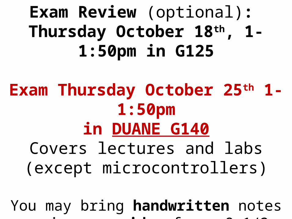
Exam Review (optional): Thursday October 18th, 1-1:50pm in G125
Exam Thursday October 25th 1-1:50pmin DUANE G140
Covers lectures and labs(except microcontrollers)
You may bring handwritten notes covering one side of one 8-1/2 x 11 piece of paper and a
calculator (no textbooks/lab manuals)
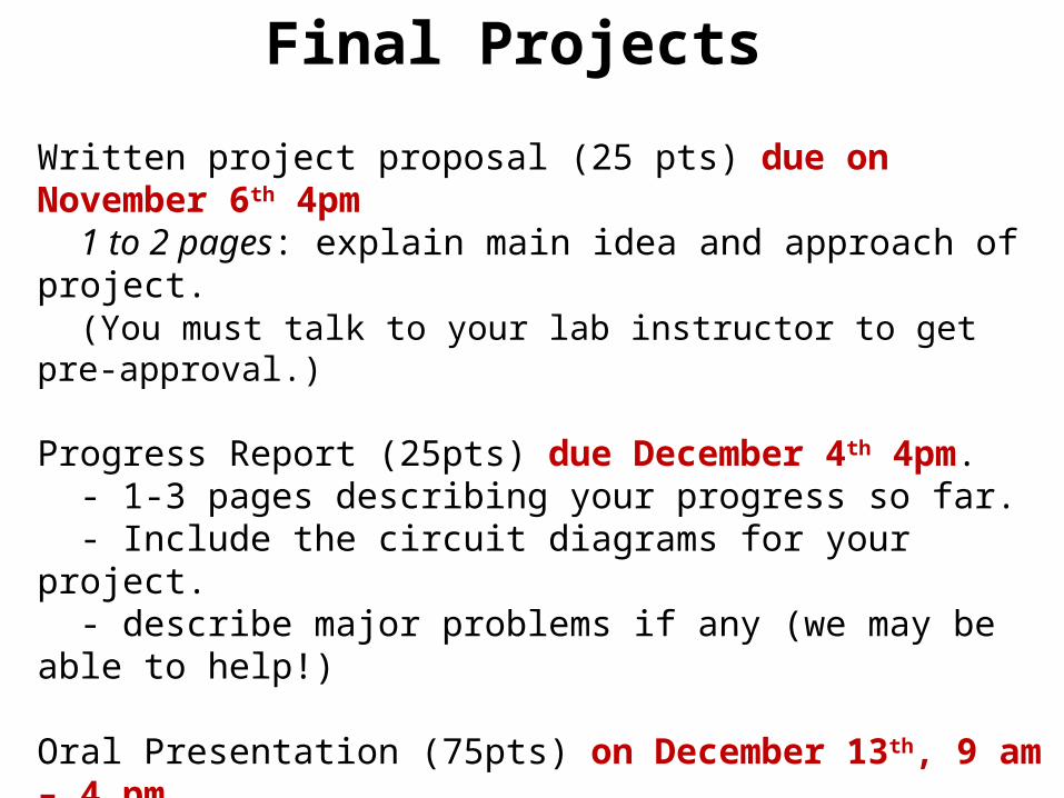
Written project proposal (25 pts) due on November 6th 4pm 1 to 2 pages: explain main idea and approach of project. (You must talk to your lab instructor to get pre-approval.)
Progress Report (25pts) due December 4th 4pm. - 1-3 pages describing your progress so far. - Include the circuit diagrams for your project. - describe major problems if any (we may be able to help!)
Oral Presentation (75pts) on December 13th, 9 am – 4 pm (There will be a sign-up sheet at the door in G230. Pick a slot!) Computer-based presentation (e.g. PowerPoint etc.) and demonstration of your circuit (show that it works.)
Final Project Report (75 pts) due on December 14th, 4 pm.
Final Projects
Types of Projects
List of old projects on website - some of them do not meet the current class requirements if you do not add an analog component
Avoid digital, high-voltage, or mechanical projects. This course is on analog, small signal electronics.
You can work alone or in groups of two. Complexity of the project must be proportional to number of students in the group
Avoid random googling!1) You must have a detailed understanding how the circuit
works. 2) You must be able to predict what happens if we modify it3) Designing a circuit from scratch vs. a googled circuit will be
considered during grading.

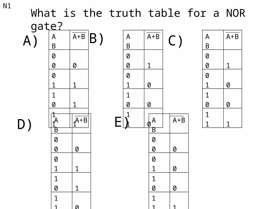
N1What is the truth table for a NOR gate?
A) B) C)
D) E)
A B A+B
0 0 0
0 1 1
1 0 1
1 1 1
A B A+B
0 0 1
0 1 0
1 0 0
1 1 0
A B A+B
0 0 1
0 1 0
1 0 0
1 1 1
A B A+B
0 0 0
0 1 1
1 0 1
1 1 0
A B A+B
0 0 0
0 1 0
1 0 0
1 1 1

N2
The following circuit containing two switches represents which logic gate?
A) NANDB) ANDC) ORD) NORE) XOR
A
B+5V out
0V
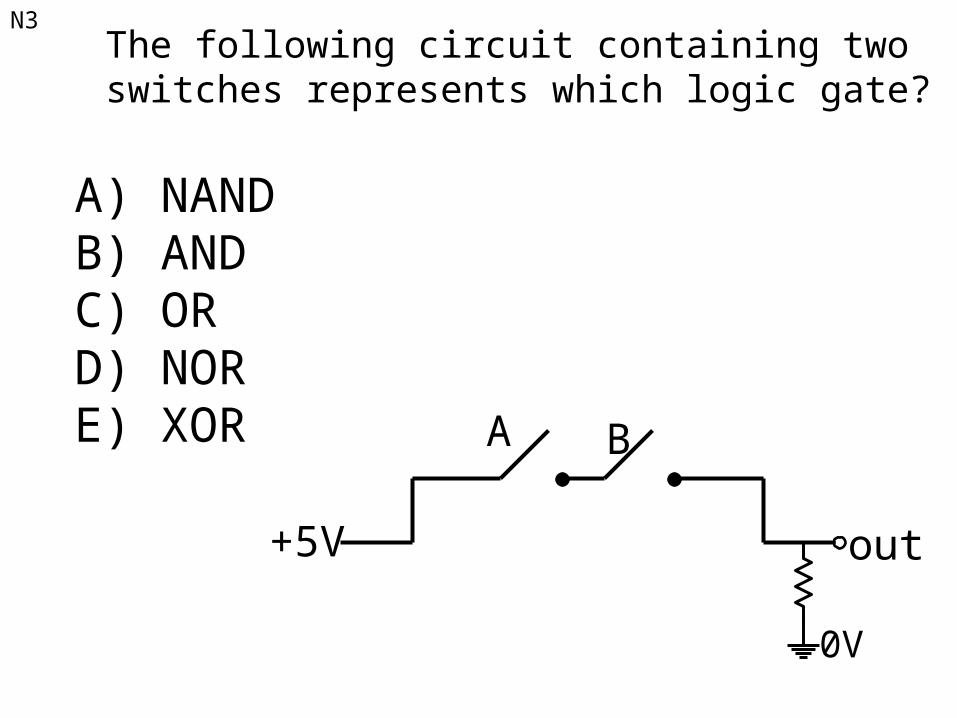
N3The following circuit containing two switches represents which logic gate?
A) NANDB) ANDC) ORD) NORE) XOR A B
+5V out
0V

N4
A ● 0 =
A) 0B) 1C) AD) A
N5
A ● 1 =
A) 0
B) 1
C) A
D) A
N6
A ● A =
A) 0
B) 1
C) A
D) A
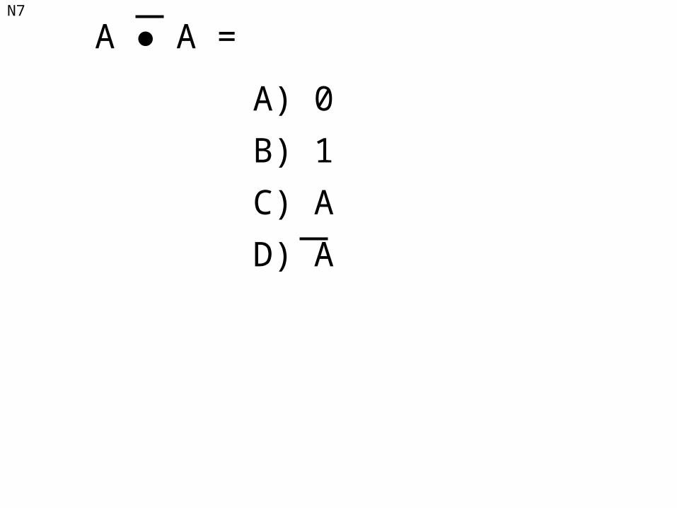
N7
A ● A =
A) 0
B) 1
C) A
D) A
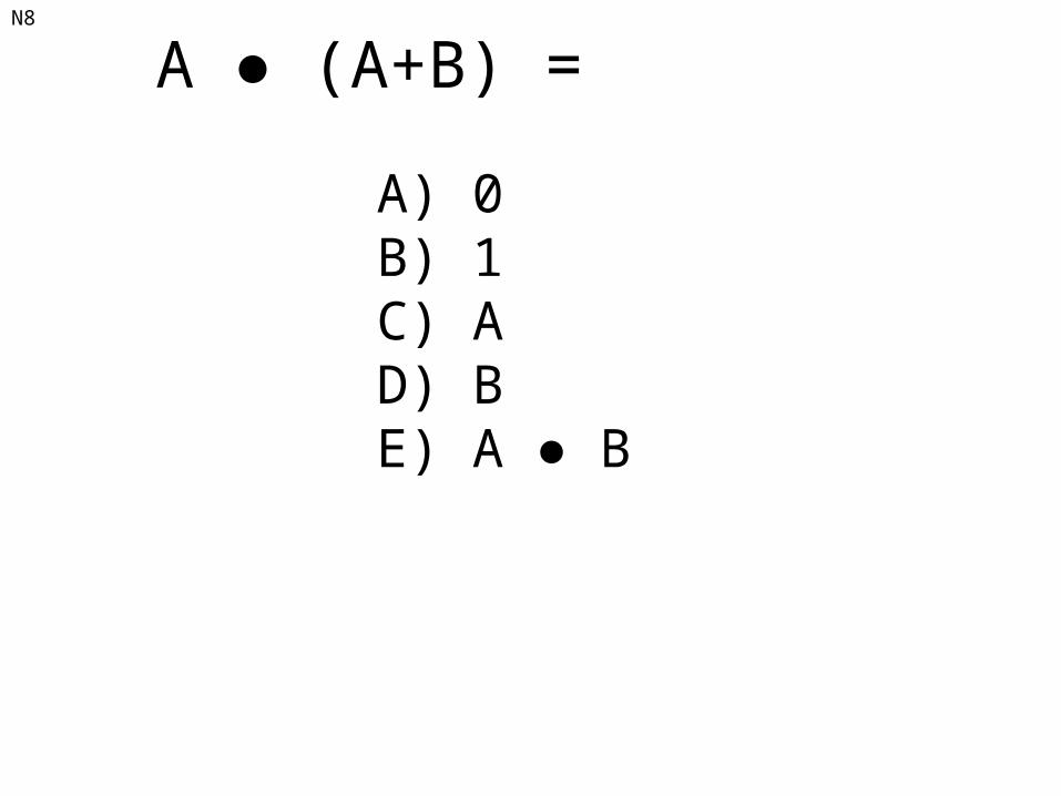
N8
A ● (A+B) =
A) 0B) 1C) AD) BE) A ● B

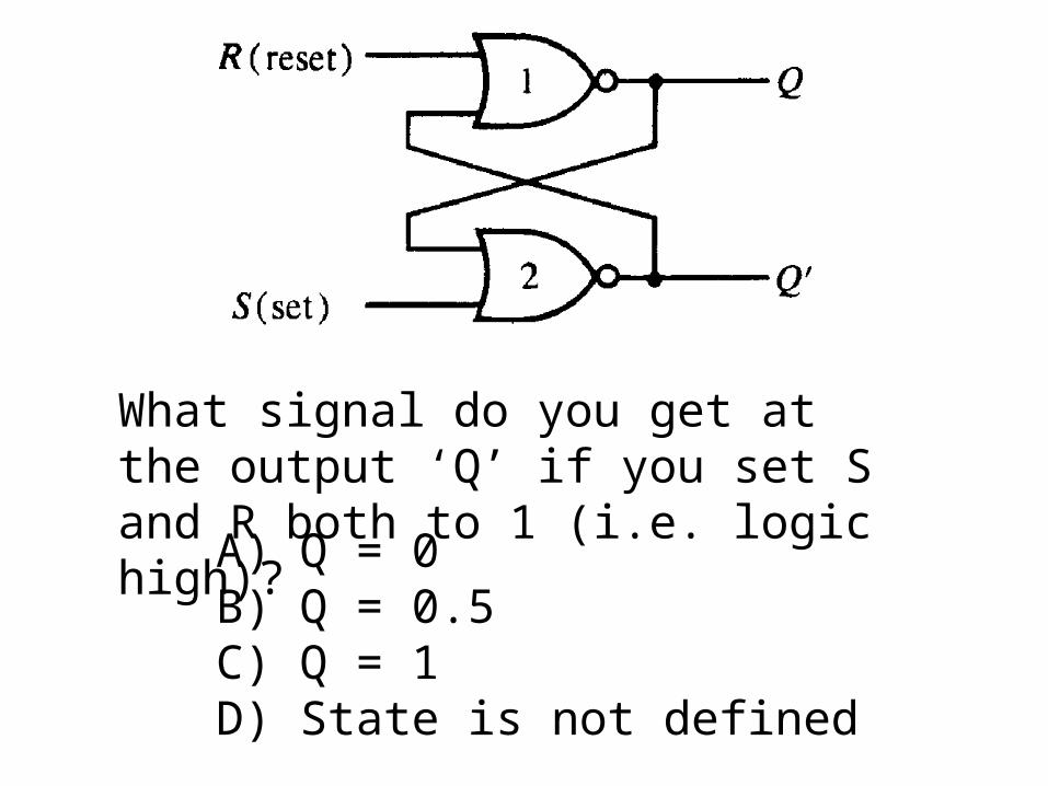
What signal do you get at the output ‘Q’ if you set S and R both to 1 (i.e. logic high)?
A) Q = 0B) Q = 0.5C) Q = 1D) State is not defined

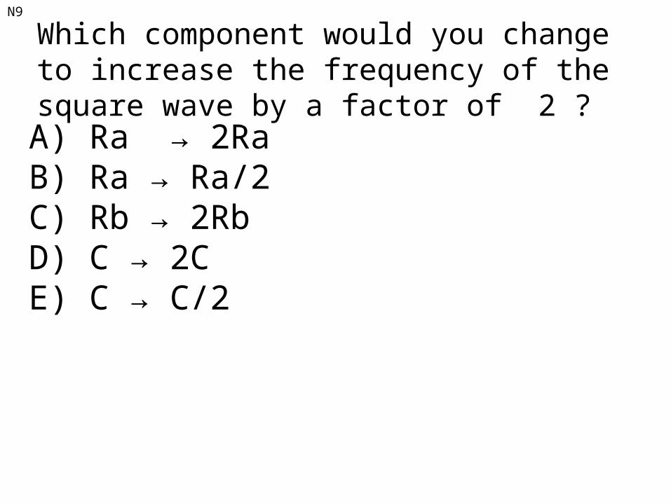
N9
Which component would you change to increase the frequency of the square wave by a factor of 2 ?
A) Ra → 2RaB) Ra → Ra/2C) Rb → 2RbD) C → 2CE) C → C/2