Embed Size (px)
Citation preview
EWS-RHRelative Humidity/Temperature
Transmitter
TM
e-mail: [email protected] latest product manuals:
www.omegamanual.info
Shop online at omega.comTM
User’s GuideTM

U.S.A.:
The information contained in this document is believed to be correct, but OMEGA accepts no liability for any errors it contains, and reserves the right to alter specifications without notice.WARNING: These products are not designed for use in, and should not be used for, human applications.
omega.com [email protected] North America:
Omega Engineering, Inc. Toll-Free: 1-800-826-6342 (USA & Canada only) Customer Service: 1-800-622-2378 (USA & Canada only) Engineering Service: 1-800-872-9436 (USA & Canada only)
Fax: (203) 359-7700 Tel: (203) 359-1660 e-mail: [email protected]
For Other Locations Visit omega.com/worldwide
TABLE OFCONTENTS
EWS-RHRelative Humidity/Temperature Transmitter
i
Page
General Description .................................................................. 1
Unpacking ................................................................................... 1
Theory of Operation .................................................................. 1
Mounting ..................................................................................... 3
RH/Temperature Calculations ................................................ 5
Calibration .................................................................................. 6
Relative Humidity Calibration Procedure ............................ 6
Temperature Calibration Procedure ...................................... 7
Specifications .............................................................................. 8
FIGURES EWS-RHRelative Humidity/Temperature Transmitter
ii
Figure Page
Figure 1A Mounting Diagram ........................................................... 3
Figure 1B EWS-MB Dimensions ..................................................... 4
Figure 2 Transmitter Wiring Examples For Current Output ... 4
Figure 3 Transmitter Wiring Examples For Voltage Output ... 4
Figure 4 Relative Humidity Calibration Procedure ................... 6
Figure 5 Temperature Calibration Procedure ............................. 7
EWS-RHRelative Humidity/Temperature Transmitter
1
General DescriptionThe OMEGA® Model EWS-RH is a combination dual output, relative humidity/temperature transmitter. A thin film temperature compensated, polymer capacitor senses relative humidity while a solid state temperature sensor measures ambient temperature. Independent user selectable 4-20 mA or 1-5 Vdc outputs are provided for both measured parameters via a terminal strip connection.
UnpackingRemove the packing list and verify that you have received all your equipment. If you have any questions about the shipment, please call our Customer Service Department at1-800-622-2378 or 203-359-1660. On the web you can find us at: www.omega.com e-mail: [email protected] you receive the shipment, inspect the container and equipment for any signs of damage. Note any evidence of rough handling in transit. Immediately report any damage to the shipping agent.
N O T E
The carrier will not honor any damage claims unless all shipping material is saved for inspection. After examining and removing contents, save packing material and carton in the event reshipment is necessary.
The following items are supplied in the box with your transmitter.This Manual, # M-3501 (1 ea.)Dewpoint Card (1 ea.)#6 Wall Anchor (2 ea.)#6 Mounting Screw (2 ea.)
EWS-RHRelative Humidity/Temperature Transmitter
2
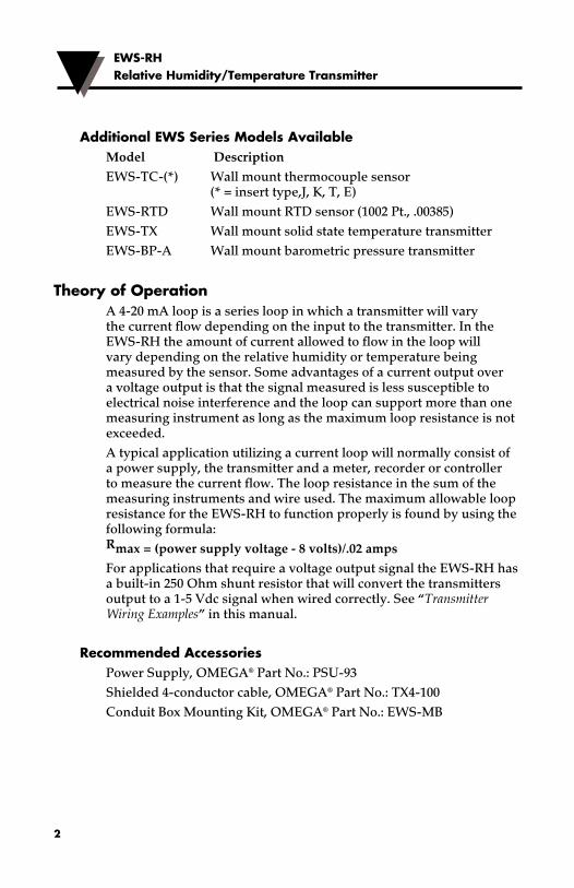
Additional EWS Series Models AvailableModel DescriptionEWS-TC-(*) Wall mount thermocouple sensor (* = insert type,J, K, T, E)EWS-RTD Wall mount RTD sensor (1002 Pt., .00385)EWS-TX Wall mount solid state temperature transmitterEWS-BP-A Wall mount barometric pressure transmitter
Theory of OperationA 4-20 mA loop is a series loop in which a transmitter will vary the current flow depending on the input to the transmitter. In the EWS-RH the amount of current allowed to flow in the loop will vary depending on the relative humidity or temperature being measured by the sensor. Some advantages of a current output over a voltage output is that the signal measured is less susceptible to electrical noise interference and the loop can support more than one measuring instrument as long as the maximum loop resistance is not exceeded.A typical application utilizing a current loop will normally consist of a power supply, the transmitter and a meter, recorder or controller to measure the current flow. The loop resistance in the sum of the measuring instruments and wire used. The maximum allowable loop resistance for the EWS-RH to function properly is found by using the following formula: Rmax = (power supply voltage - 8 volts)/.02 ampsFor applications that require a voltage output signal the EWS-RH has a built-in 250 Ohm shunt resistor that will convert the transmitters output to a 1-5 Vdc signal when wired correctly. See “Transmitter Wiring Examples” in this manual.
Recommended Accessories Power Supply, OMEGA® Part No.: PSU-93Shielded 4-conductor cable, OMEGA® Part No.: TX4-100 Conduit Box Mounting Kit, OMEGA® Part No.: EWS-MB
EWS-RHRelative Humidity/Temperature Transmitter
3
N O T E
These units are not designed, nor recommended for medical, Explosive Environment or outdoor applications.
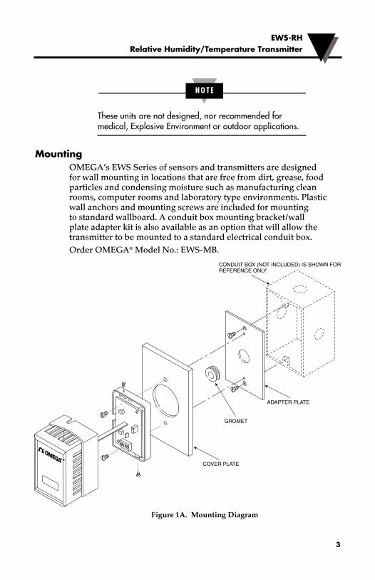
MountingOMEGA’s EWS Series of sensors and transmitters are designed for wall mounting in locations that are free from dirt, grease, food particles and condensing moisture such as manufacturing clean rooms, computer rooms and laboratory type environments. Plastic wall anchors and mounting screws are included for mounting to standard wallboard. A conduit box mounting bracket/wall plate adapter kit is also available as an option that will allow the transmitter to be mounted to a standard electrical conduit box. Order OMEGA® Model No.: EWS-MB.
Figure 1A. Mounting Diagram
COVER PLATE
GROMET
EWSMountingDrawing.eps
ADAPTER PLATE
CONDUIT BOX (NOT INCLUDED) IS SHOWN FORREFERENCE ONLY
®
EWS-RHRelative Humidity/Temperature Transmitter
4
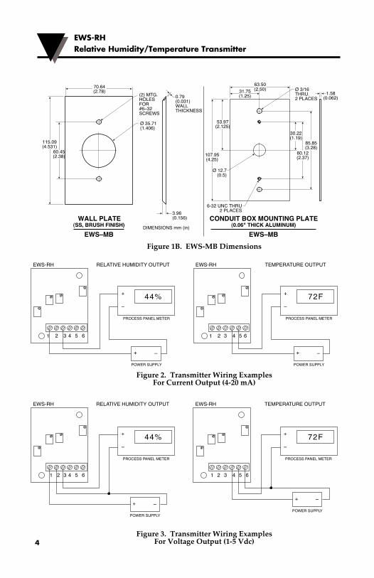
Figure 1B. EWS-MB Dimensions
Figure 2. Transmitter Wiring Examples For Current Output (4-20 mA)
Figure 3. Transmitter Wiring Examples For Voltage Output (1-5 Vdc)
EWSTransmitWireExCurrent.eps
EWS-RH RELATIVE HUMIDITY OUTPUT
PROCESS PANEL METER
POWER SUPPLY
1 6
44%+
+
–
–
5432
EWS-RH TEMPERATURE OUTPUT
PROCESS PANEL METER
POWER SUPPLY
1 6
72F+
+
–
–
5432EWSTransmitWireExVoltage.eps
EWS-RH RELATIVE HUMIDITY OUTPUT
PROCESS PANEL METER
POWER SUPPLY
1 6
44%+
+
–
–
5432
EWS-RH TEMPERATURE OUTPUT
PROCESS PANEL METER
POWER SUPPLY
1 6
72F+
+
–
–
5432
60.12(2.37)
30.22(1.19)
31.75(1.25)
85.85(3.28)
60.45(2.38)
70.64(2.78)
DIMENSIONS mm (in)
(2) MTG. HOLES FOR#6–32 SCREWS
0.79(0.031)WALLTHICKNESS
3.96(0.156)
115.09(4.531)
63.50(2.50)
CONDUIT BOX MOUNTING PLATE(0.06" THICK ALUMINUM)
EWS–MB
1.58(0.062)
53.97(2.125)
107.95(4.25)
Ø 3/16THRU.2 PLACES
Ø 35.71 (1.406)
Ø 12.7(0.5)
6-32 UNC THRU2 PLACES
WALL PLATE(SS, BRUSH FINISH)
EWS–MB
EWS-RHRelative Humidity/Temperature Transmitter
5
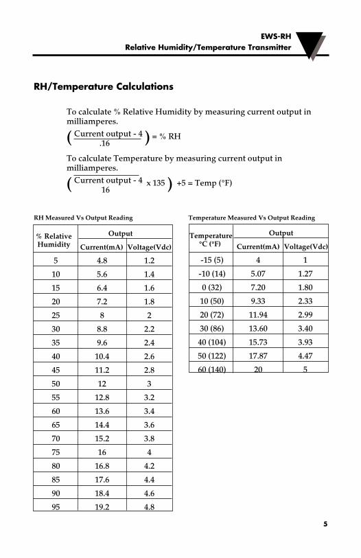
RH/Temperature Calculations
To calculate % Relative Humidity by measuring current output in milliamperes.
( Current output - 4 ) = % RH .16
To calculate Temperature by measuring current output in milliamperes.
( Current output - 4 x 135 ) +5 = Temp (°F) 16
RH Measured Vs Output Reading Temperature Measured Vs Output Reading
Temperature Output
°C (°F) Current(mA) Voltage(Vdc)
-15 (5) 4 1
-10 (14) 5.07 1.27
0 (32) 7.20 1.80
10 (50) 9.33 2.33
20 (72) 11.94 2.99
30 (86) 13.60 3.40
40 (104) 15.73 3.93
50 (122) 17.87 4.47
60 (140) 20 5
% Relative Output
Humidity Current(mA) Voltage(Vdc)
5 4.8 1.2
10 5.6 1.4
15 6.4 1.6
20 7.2 1.8
25 8 2
30 8.8 2.2
35 9.6 2.4
40 10.4 2.6
45 11.2 2.8
50 12 3
55 12.8 3.2
60 13.6 3.4
65 14.4 3.6
70 15.2 3.8
75 16 4
80 16.8 4.2
85 17.6 4.4
90 18.4 4.6
95 19.2 4.8
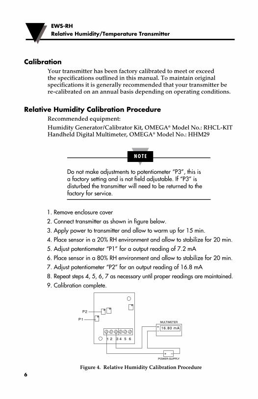
CalibrationYour transmitter has been factory calibrated to meet or exceed the specifications outlined in this manual. To maintain original specifications it is generally recommended that your transmitter be re-calibrated on an annual basis depending on operating conditions.
Relative Humidity Calibration Procedure Recommended equipment:Humidity Generator/Calibrator Kit, OMEGA® Model No.: RHCL-KIT Handheld Digital Multimeter, OMEGA® Model No.: HHM29
N O T E
Do not make adjustments to potentiometer “P3”, this is a factory setting and is not field adjustable. If “P3” is disturbed the transmitter will need to be returned to the factory for service.
1. Remove enclosure cover2. Connect transmitter as shown in figure below.3. Apply power to transmitter and allow to warm up for 15 min. 4. Place sensor in a 20% RH environment and allow to stabilize for 20 min.5. Adjust potentiometer “P1” for a output reading of 7.2 mA6. Place sensor in a 80% RH environment and allow to stabilize for 20 min.7. Adjust potentiometer “P2” for an output reading of 16.8 mA8. Repeat steps 4, 5, 6, 7 as necessary until proper readings are maintained.9. Calibration complete.
Figure 4. Relative Humidity Calibration Procedure
EWS-RHRelative Humidity/Temperature Transmitter
6
WSRelHumidityCalib.eps
MULTIMETER
POWER SUPPLY
1 6
+
+
–
–
5432
16.80 mA
P1
P2
EWS-RHRelative Humidity/Temperature Transmitter
7
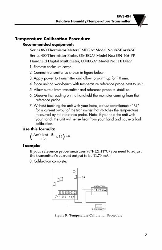
Temperature Calibration Procedure Recommended equipment:
Series 860 Thermistor Meter OMEGA® Model No. 865F or 865CSeries 400 Thermistor Probe, OMEGA® Model No.: ON-406-PPHandheld Digital Multimeter, OMEGA® Model No.: HHM29
1. Remove enclosure cover.2. Connect transmitter as shown in figure below.3. Apply power to transmitter and allow to warm up for 10 min. 4. Place unit on workbench with temperature reference probe next to unit.5. Allow output from transmitter and reference probe to stabilize.6. Observe the reading on the handheld thermometer coming from the
reference probe.7. Without touching the unit with your hand, adjust potentiometer “P4”
for a current output of the transmitter that matches the temperature measured by the reference probe. Note: if you hold the unit with your hand, the unit will sense heat from your hand and cause a bad calibration.
Use this formula:
( Ambient - 5 x 16) +4 135
Example:If your reference probe measures 70°F (21.11°C) you need to adjust the transmitter’s current output to be 11.70 mA.
8. Calibration complete.
Figure 5. Temperature Calibration Procedure
EWSTemperatureCalib.eps
MULTIMETER
POWER SUPPLY
1 6
+
+
–
–
5432
11.70 mA
P4
EWS-RHRelative Humidity/Temperature Transmitter
8
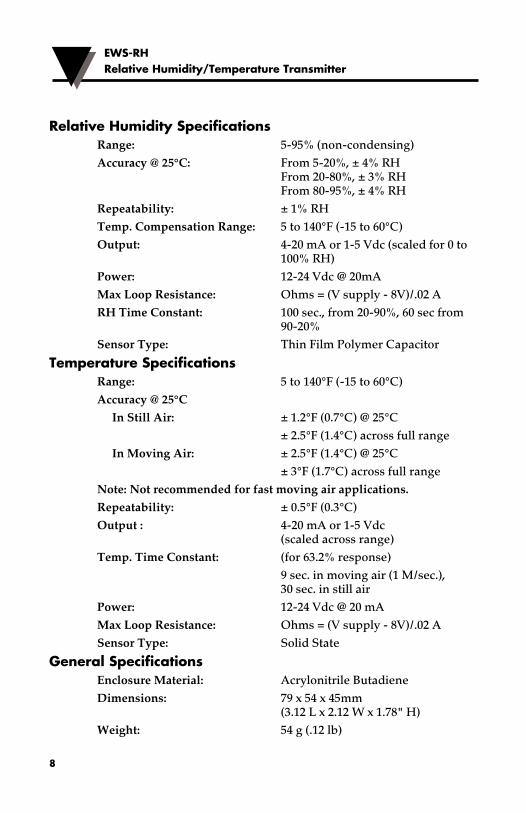
Relative Humidity SpecificationsRange: 5-95% (non-condensing)Accuracy @ 25°C: From 5-20%, ± 4% RH From 20-80%, ± 3% RH From 80-95%, ± 4% RHRepeatability: ± 1% RHTemp. Compensation Range: 5 to 140°F (-15 to 60°C)Output: 4-20 mA or 1-5 Vdc (scaled for 0 to 100% RH)Power: 12-24 Vdc @ 20mAMax Loop Resistance: Ohms = (V supply - 8V)/.02 ARH Time Constant: 100 sec., from 20-90%, 60 sec from 90-20%Sensor Type: Thin Film Polymer Capacitor
Temperature SpecificationsRange: 5 to 140°F (-15 to 60°C) Accuracy @ 25°C In Still Air: ± 1.2°F (0.7°C) @ 25°C ± 2.5°F (1.4°C) across full range In Moving Air: ± 2.5°F (1.4°C) @ 25°C ± 3°F (1.7°C) across full rangeNote: Not recommended for fast moving air applications.Repeatability: ± 0.5°F (0.3°C)Output : 4-20 mA or 1-5 Vdc (scaled across range)Temp. Time Constant: (for 63.2% response) 9 sec. in moving air (1 M/sec.), 30 sec. in still airPower: 12-24 Vdc @ 20 mAMax Loop Resistance: Ohms = (V supply - 8V)/.02 ASensor Type: Solid State
General SpecificationsEnclosure Material: Acrylonitrile ButadieneDimensions: 79 x 54 x 45mm (3.12 L x 2.12 W x 1.78" H)Weight: 54 g (.12 lb)

9
NOTES:
EWS-RHRelative Humidity/Temperature Transmitter

10
NOTES:
EWS-RHRelative Humidity/Temperature Transmitter
WARRANTY/DISCLAIMEROMEGA ENGINEERING, INC. warrants this unit to be free of defects in materials and workmanship for a period of 13 months from date of purchase. OMEGA’s WARRANTY adds an additional one (1) month grace period to the normal one (1) year product warranty to cover handling and shipping time. This ensures that OMEGA’s customers receive maximum coverage on each product. If the unit malfunctions, it must be returned to the factory for evaluation. OMEGA’s Customer Service Department will issue an Authorized Return (AR) number immediately upon phone or written request. Upon examination by OMEGA, if the unit is found to be defective, it will be repaired or replaced at no charge. OMEGA’s WARRANTY does not apply to defects resulting from any action of the purchaser, including but not limited to mishandling, improper interfacing, operation outside of design limits, improper repair, or unauthorized modification. This WARRANTY is VOID if the unit shows evidence of having been tampered with or shows evidence of having been damaged as a result of excessive corrosion; or current, heat, moisture or vibration; improper specification; misapplication; misuse or other operating conditions outside of OMEGA’s control. Components in which wear is not warranted, include but are not limited to contact points, fuses, and triacs.OMEGA is pleased to offer suggestions on the use of its various products. However, OMEGA neither assumes responsibility for any omissions or errors nor assumes liability for any damages that result from the use of its products in accordance with information provided by OMEGA, either verbal or written. OMEGA warrants only that the parts manufactured by the company will be as specified and free of defects. OMEGA MAKES NO OTHER WARRANTIES OR REPRESENTATIONS OF ANY KIND WHATSOEVER, EXPRESSED OR IMPLIED, EXCEPT THAT OF TITLE, AND ALL IMPLIED WARRANTIES INCLUDING ANY WARRANTY OF MERCHANTABILITY AND FITNESS FOR A PARTICULAR PURPOSE ARE HEREBY DISCLAIMED. LIMITATION OF LIABILITY: The remedies of purchaser set forth herein are exclusive, and the total liability of OMEGA with respect to this order, whether based on contract, warranty, negligence, indemnification, strict liability or otherwise, shall not exceed the purchase price of the component upon which liability is based. In no event shall OMEGA be liable for consequential, incidental or special damages.CONDITIONS: Equipment sold by OMEGA is not intended to be used, nor shall it be used: (1) as a “Basic Component” under 10 CFR 21 (NRC), used in or with any nuclear installation or activity; or (2) in medical applications or used on humans. Should any Product(s) be used in or with any nuclear installation or activity, medical application, used on humans, or misused in any way, OMEGA assumes no responsibility as set forth in our basic WARRANTY / DISCLAIMER language, and, additionally, purchaser will indemnify OMEGA and hold OMEGA harmless from any liability or damage whatsoever arising out of the use of the Product(s) in such a manner.
RETURN REQUESTS/INQUIRIESDirect all warranty and repair requests/inquiries to the OMEGA Customer Service Department. BEFORE RETURNING ANY PRODUCT(S) TO OMEGA, PURCHASER MUST OBTAIN AN AUTHORIZED RETURN (AR) NUMBER FROM OMEGA’S CUSTOMER SERVICE DEPARTMENT (IN ORDER TO AVOID PROCESSING DELAYS). The assigned AR number should then be marked on the outside of the return package and on any correspondence.The purchaser is responsible for shipping charges, freight, insurance and proper packaging to prevent breakage in transit.
OMEGA’s policy is to make running changes, not model changes, whenever an improvement is possible. This affords our customers the latest in technology and engineering.OMEGA is a registered trademark of OMEGA ENGINEERING, INC.© Copyright 2014 OMEGA ENGINEERING, INC. All rights reserved. This document may not be copied, photocopied, reproduced, translated, or reduced to any electronic medium or machine-readable form, in whole or in part, without the prior written consent of OMEGA ENGINEERING, INC.
FOR WARRANTY RETURNS, please have the following information available BEFORE contacting OMEGA:1. Purchase Order number under which the product was PURCHASED,2. Model and serial number of the product
under warranty, and3. Repair instructions and/or specific
problems relative to the product.
FOR NON-WARRANTY REPAIRS, consult OMEGA for current repair charges. Have the following information available BEFORE contacting OMEGA:1. Purchase Order number to cover the
COST of the repair,2. Model and serial number of theproduct, and3. Repair instructions and/or specific problems relative to the product.
M3501/0818
Where Do I Find Everything I Need for Process Measurement and Control?
OMEGA…Of Course!Shop online at omega.comTM
TEMPERATUREMU Thermocouple, RTD & Thermistor Probes, Connectors, Panels & Assemblies MU Wire: Thermocouple, RTD & ThermistorMU Calibrators & Ice Point ReferencesMU Recorders, Controllers & Process MonitorsMU Infrared Pyrometers
PRESSURE, STRAIN AND FORCEMU Transducers & Strain GagesMU Load Cells & Pressure GagesMU Displacement TransducersMU Instrumentation & Accessories
FLOW/LEVELMU Rotameters, Gas Mass Flowmeters & Flow ComputersMU Air Velocity IndicatorsMU Turbine/Paddlewheel SystemsMU Totalizers & Batch Controllers
pH/CONDUCTIVITYMU pH Electrodes, Testers & AccessoriesMU Benchtop/Laboratory MetersMU Controllers, Calibrators, Simulators & PumpsMU Industrial pH & Conductivity Equipment
DATA ACQUISITIONMU Data Acquisition & Engineering SoftwareMU Communications-Based Acquisition SystemsMU Plug-in Cards for Apple, IBM & CompatiblesMU Data Logging SystemsMU Recorders, Printers & Plotters
HEATERSMU Heating CableMU Cartridge & Strip HeatersMU Immersion & Band HeatersMU Flexible HeatersMU Laboratory Heaters
ENVIRONMENTAL MONITORING AND CONTROLMU Metering & Control InstrumentationMU RefractometersMU Pumps & TubingMU Air, Soil & Water MonitorsMU Industrial Water & Wastewater TreatmentMU pH, Conductivity & Dissolved Oxygen Instruments