Embed Size (px)
Citation preview
EWPIIB-7WallingShapeandMaterialsUsageR5.docx 02/08/2016
1
Energy&Low-incomeTropicalHousing(ELITH)WorkingPaperEWPIIB-7
WallingShapeandMaterialsUsage-Plane,Buttressed,CrenelatedandWavyWalls
ByT.H.Thomas,WarwickUniversity,2016
ABSTRACT
Astraightlongboundarywallshouldgenerallyhaveaslendernessratiooflessthan14toattain
sufficientlateralstrengthandstiffness.Thusa2.4mwallwouldneedtobe17cmthick,i.e.fullbrick
(20cm)ratherthanhalfbrick(10cm).Athinner,cheaper,half-brickwallcouldbeusedbutrequires
buttressesplacedtypically3mapart.Therearehowevertwoprovenalternativestobuttressing,
namelyemployingawavyoracrenelatedwallplan,thatuselessmaterialbutmayincursuch
penaltiesascreatingroomsthatarehardtofurnishorboundariesthatdonotmatchplotownership.
Thepaperidentifies4structuraland3non-structuralperformancecriteriaforwallsandagainst
thesecomparesthe4wall-planshapeslistedinthetitle.Takinga20cmfull-brickwallasdatum,the
relativestiffnessperbrickusedfora40cm-deepbuttressedwallisaboutx3andtherelativelateral
strengthisaboutx1.For40cm-deepcrenelatedwalls,thecorrespondingratiosarex6andx3.For
40cm-deepwavywallsthecorrespondingratiosarex13andx4.Thusthinwavyandcrenelatedwall
plansoffersignificantlybetterperformance‘perbrick’underlateralforcesthandothinbuttressed
orthickstraightwalls.
CONTENTS
1 Introduction
2 Fourshapevariants:plain,buttressed,crenelatedandwavy
3 Wallingmaterialsandmethodsofconstruction
4 Single-storey,two-storeyandmulti-storeywalling
5 Criteriaforcomparison
6 Plainwalls
7 Buttressedwalls
8 Crenellatedwalls
9 Wavy(serpentine)walls
10 Numericalcomparisonsofthe4wallplans
11 Conclusions
12 Bibliography
Appendix:CalculationsforConstantRadiusWavyWalls
EWPIIB-7WallingShapeandMaterialsUsageR5.docx 02/08/2016
2
1 Introduction
ThisELITHWorkingPaperisoneofaset(WPIIB-4)examiningtheenergyembodiedinwallingand
howitmightbereduced.WPIIB-4-1(Wallingstiffnessandstrengthintropicalhousing)developeda
simplisticanalysisforplanewalling.Thispaper,WPIIB-4-3,usesthattomakeacomparisonofthree
other walling plans. For purposes of comparing these different plans (shapes) we can take as a
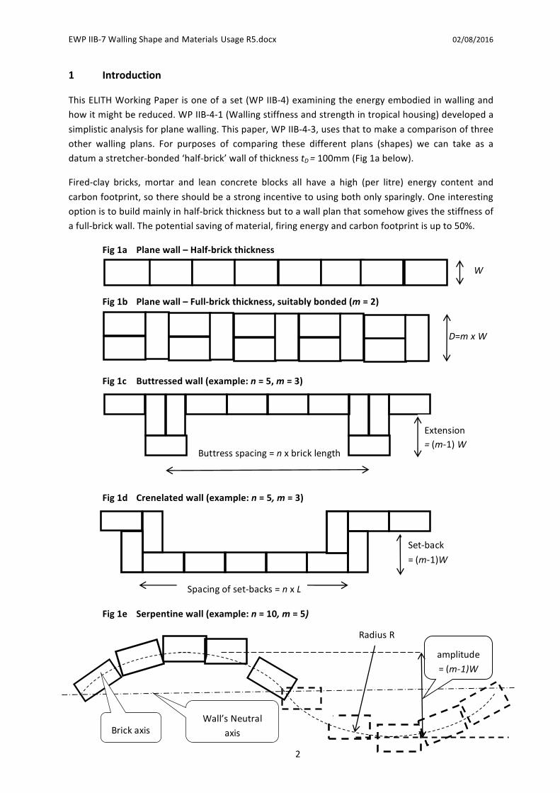
datumastretcher-bonded‘half-brick’wallofthicknesstD=100mm(Fig1abelow).
Fired-clay bricks, mortar and lean concrete blocks all have a high (per litre) energy content and
carbonfootprint,sothereshouldbeastrongincentivetousingbothonlysparingly.Oneinteresting
optionistobuildmainlyinhalf-brickthicknessbuttoawallplanthatsomehowgivesthestiffnessof
afull-brickwall.Thepotentialsavingofmaterial,firingenergyandcarbonfootprintisupto50%.
Fig1a Planewall–Half-brickthickness
Fig1b Planewall–Full-brickthickness,suitablybonded(m=2)
Fig1c Buttressedwall(example:n=5,m=3)
Fig1d Crenelatedwall(example:n=5,m=3)
Fig1e Serpentinewall(example:n=10,m=5)
W
D=mxW
Extension=(m-1)W
Buttressspacing=nxbricklength
Spacingofset-backs=nxL
Set-back
=(m-1)W
RadiusR
amplitude
=(m-1)W
Brickaxis
Wall’sNeutral
axis

EWPIIB-7WallingShapeandMaterialsUsageR5.docx 02/08/2016
3
Howeverforbothload-bearinghousewallsandforboundarywalls,afull-brick(Fig1b)ratherthan
half-brick wall is usually employed where, provided the brick proportions are properly chosen, a
varietyof ‘bonds’ canbeused tohold thewall strongly together.WithanEnglishbond (alternate
coursesofheadersandstretcherswithoutinternalorexternalcontinuousverticaljoints)theout-of-
planestiffnessofthefullbrickwallisabout8timesthatofthehalf-brickoneandthelateralloading
resistanceis4timeshigher.
Brickwork is ancient. However bonded fired-clay bricks were not commonly used in Europe for
housewallinguntilabout1800andthecorrespondingdates inAsiaandAfricamightbe1950and
1990 respectively.Wattle and daub (poles andmud), dried soil blocks,matting on poleswere all
dominantwalling techniques in thetropicsuntil late in the20thcentury.Moreover inmanyplaces
the full-brick, bonded, fired-clay brick wall (and its ‘cavity wall’ variant) have given way tomore
complexdesignsor to theuseof larger cementitioushollowblocks. Blockwalls, that are typically
150mmthick,haveastiffnessintermediatebetweenthethoseof112mmhalf-brickand225mmfull-
brickwalling.
Other brickwalls can be described by theirmean thickness tm expressed as amultipleu of brickthicknessW. The ratio u = tm/tD will also equal the number of bricks per course divided by the
numberofbricks inadatumwallof thesame length.Thus foradouble-thicknessplanewall,U=2andm=2.
For external house walls and for boundary walls, such double-depth brick (i.e. 200mm deep) is
commonly used to achieve adequate stiffness and strength. Neglecting renders or plasters, this
requiresabout420kgofbrick+mortarpersquaremeterofwalling.Byusingasingle-brickthickness
(i.e.100mm),themasspersquaremeterofbrickwallingcouldbereducedtoabout230kg.Orwith
some more complex wall-shape for which 1<U<2, we might achieve a lesser, but still valuable,
weightsavingrelativetothedouble-depthnorm.
To achieveu< 2,much of thewall lengthmust be of single-brick thickness. However to achieve
adequateoverallstiffnessandstrength,thelocalaxesofsuchsingle-bricksectionsneedtobeoffset
fromtheoverallwallaxis.AmeasuremisthereforeusedtodescribethewalldepthDasamultiple
ofW (i.e. D =m xW). Thus (see Fig 1c) for a buttressedwall, (m-1) xW is the protrusion of the
buttresses.Foracrenelatedwall,seeFig1d,Dthedistancebetweenthe‘front’and‘rear’faces;forawavywall(Fig1e)itisthemaximumdistancebetweenthosefaces.Forallthreewallshapes,the
walldepthisD=mxWandthemeanthickness isuxW.As increasingmresults ingreater lateral
stiffnessandstrength,yet increasingu incursgreatercost,weare interested inwaysof increasingthe‘materialsproductivity’ratiom/u.
The energy consumed, and the GHGs emitted while producing house walling, depend on the
quantity ofmaterial used. This in turn, for a givenwall area, is roughly proportional to themean
thicknesstmofthewall.InthisWorkingPaperwelookonlyattheimpactofwallshapeonthatmean
thickness. It is however of little value to compare the mean thickness of walls of very different
performances.Thereforeweshouldeitherspecifyaparticularperformanceandcomparethemean
thicknessesof rivaldesignsthatachieve it,orweshouldgeneratesomesortofproductivity figure
whose numerator is a performance measure and whose denominator is wall cost or mean wall
thickness.

EWPIIB-7WallingShapeandMaterialsUsageR5.docx 02/08/2016
4
Tokeepcomparisons simple,wewill restrictourselves towallsof a specifiedheight– thedatum,
buttressed,crenelatedandsinuouswallsareassumedtobethesameheight.
As housewalling andboundarywalling are typically 225mm thick,wemight choose to adjust the
various performance criteria to “that achieved by a 225mm-thick plane wall”. This will simplify
visualisationofwallproperties,astb,p ,tc,pandts,pbecometherespectivemeanwallthicknessesof
buttressed,crenelatedandsinuouswallstogivethesameperformanceasa200mmplanewall.
Inatropicalsetting,someaspectsofperformance(forexamplewindandnoiseexclusion)arelittle
affected by wall design. In this paper we therefore concentrate on performance factors that arehighly affectedby shapeor thickness, namely structural strength and stiffness.We choosenot to
considerheretheeffectofusingdifferentwallingmaterials.
Theresistanceandstiffnessofevenplanewallingiscomplextocalculate,forexampleaccordingto
Eurocode6. Fornon-uniformwalling, suchasbuttressed, crenelatedand sinuous, analysis is even
morecomplex.Thereforethispaperemployshighlysimplifiedanalysis,whereverpossiblelinkedto
footprintareaA,secondmomentofareaIandbending-sectionmodulusZ.
2 Fourshapevariants:plain,buttressed,crenelatedandwavy
Plane walling (Fig 1a and 1b) is of uniform thickness (mean thickness = maximum thickness). To
achieveadequateresistancetoout-of-planeforces,thisthicknessmaybequitelargeentailingmuch
material.Planewallingiseasytoerectandinhousingproducesconvenientroomshapes.
Buttressedwalling(Fig1c)hasuneventhickness.Itseffectivethicknessisincreasedbytheaddition
ofperiodicbuttressesinawaythat–foragivenstiffnessorlateralstrength–useslessmaterialthan
a plane wall. However incorporating well-bonded buttresses requires some skill, may result in
inconvenientroomshapesandmayconsumemorelandareathanaplainwall.Acellularfloorplan
(many tiny rooms) is the ultimate form of buttressing but is rarely acceptable to a house’s
occupants.
Crenelatedwalls (Fig1d) carry thebuttressing idea furtherwithmostof thewall beingdisplaced,
alternately, to one side or the other of the wall’s axis. This substantially increases stiffness and
resistancetooutofplaneforceswithoutmuch increasingthemeanwall thicknessandhencewall
cost.Againskillisrequiredtoachieveproperbondingandroomshapeissomewhatcompromised.
Plane,buttressedandcrenelatedwallingisnormallystraight,wavyserpentinewalling,onceknown
as‘crinkle-cranklewalling’(Fig1e)isnot.Awavywalluseshardlymorematerialthanastraightone
of the same thickness but (provided it holds together and does not ‘rack’ when loaded) ismany
times stiffer and more force-resisting. The penalty is the inconvenient shape (in a world where
almost all fittings and furniture are rectangular) and any liability tomore complex failuremodes.
However for some application (garden walls), and some architects, the very sinuosity can be
consideredavirtue.Zig-zagwallingcanbeconsideredaspecialcaseofserpentinewalling.
3 Wallingmaterialsandmethodsofconstruction
Wallingbeingaveryancienttechnology,comesinamyriadofforms.Thetwomost-commonforms
ofwallingassemblyaremonolithicandblock. In the former therelevantmaterial isassembledon
EWPIIB-7WallingShapeandMaterialsUsageR5.docx 02/08/2016
5
siteasacontinuum,eitherusingshutteringorusingaformersuchasaverticalmesh.Thereissome
scopeforlightcompressionofthewallingmaterialbyapplicationofsloworimpactforces,butany
such compression is limited by the bursting strength of the shuttering. By contrast with block or
brickorstonewalling,theindividualunitsareassembledwithoutshuttering,usuallybyusingeither
a jointing compound such asmortar or an arrangementof interlocks. Becauseeachblock/brick is
small,before it isbroughttosite itcanbesubjectedtosubstantialpressuresortemperatures ina
press or furnace, thereby cheaply improving its mechanical properties (strength, hardness,
accuracy).Howeverblockwallingmayhavealmostnotensilestrengthatthejointsbetweenblocks.
Its structural analysis commonly entails assuming a complete absence of tensile bonding unless
reinforcingorposttensioningisemployed.
Voidswithinawallweshallregardas‘materialproperties’affectingmaterialdensities,strengthsetc.
For the purposes of comparing wall shapes, we will assume all rival shapes employ the same
materials.Aproblemmayapplywith‘cavity’walls,inthatcavitiescaneasilybecombinedwithplane
walling but not with buttressing, tessellation or serpentine form. However although cavity
construction was widely used in temperate countries in the 20th century to restrict damp
penetration, ithassincesupersededbyothertechniques it isuncommoninthetropicsandsowill
notbeconsideredfurtherinthisWorkingPaper.
Wallscanbenon-homogenous,forexamplehavingtwoleavesmadeofdifferentmaterialsorhaving
surfacerenders/plasters.Eventhoughtheyareusuallythinsuchrenderscancontributesignificantly
towallperformance.AgaininthisWorkingPapersuchrefinementswillbeignored.
Themainpurposesofwallingare(i)asaclimate-excludingcurtainor(ii)asacombinationofcurtain
andstructuralsupport.Curtainwalling(i)onlyhastocarryitsownratherlightweightandwithstand
localforcesincludingimpacts;moststructuralloadsinsuchbuildingsarecarriedbyameshofbeams
andcolumnsbetweenwhichthewalling isstretched.Curtainwalling isusuallyofbrick/blockorof
factory-madepanel,orofglass.Bycontrast,‘structural’or‘load-bearing’walling(ii)carriesnotonly
itsownweight(includingtheweightofthewallingofhigherfloors)butalsothetransferredweight
ofsuspendedfloorsandroofing. Italsoresiststhehorizontal forcesdueto itsconnectiontothose
more horizontal elements. A further horizontal force on load-bearing walls is that due to wind-
loading,seismicaccelerationsandimpacts.
4 Single-storey,two-storeyandmulti-storeywalling
Veryhighbuildingscompriseastructuralframeandacoveringofcurtainwalling,hangingfromthat
frame.Historically load-bearingwalling (withno frame)wasuseduptoaboutsix stories,however
the exact analysis of such high walls was not possible and they had to be built with large but
indeterminatesafetyfactors.Thisincreasedtheircostandprovokedtheearly20thcenturychangeto
framed construction for all high-rise buildings. More recently the analysis of multi-storey load-
bearingbrickwallshasbeenadvanced[Eurocode61996,Hendry1997]andthereisaslightrevival
of interest inthem.Forthepurposesofthispaperwewillconsideronly1,2and4storeyhousing
withload-bearingwalls.Single-storeyrepresentsthegreatbulkofruralhousinginthetropics.Two-
storeyconstructionisnowcommonintownsandisalsoobservableinstiltforminruralSEAsia.Four
storeyhousingisusuallyintheformofapartments,oneormoretoeachfloor.ELITHWorkingPaper
IIB-3comparesthepropertiesofhousingofthesethreeheights.
EWPIIB-7WallingShapeandMaterialsUsageR5.docx 02/08/2016
6
5 Criteriaforcomparison
Aswellascost(foragivenmaterial,thisisstronglycorrelatedwithmeanthicknesstm),weareinterestedforhouse-wallingin
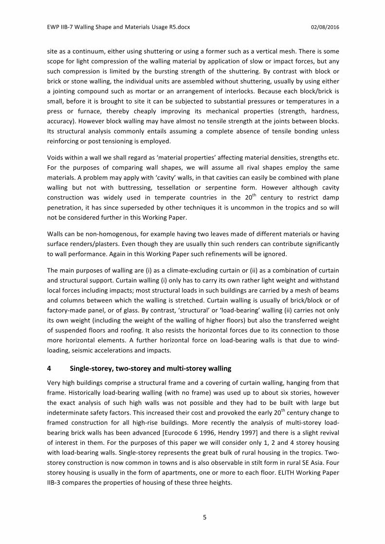
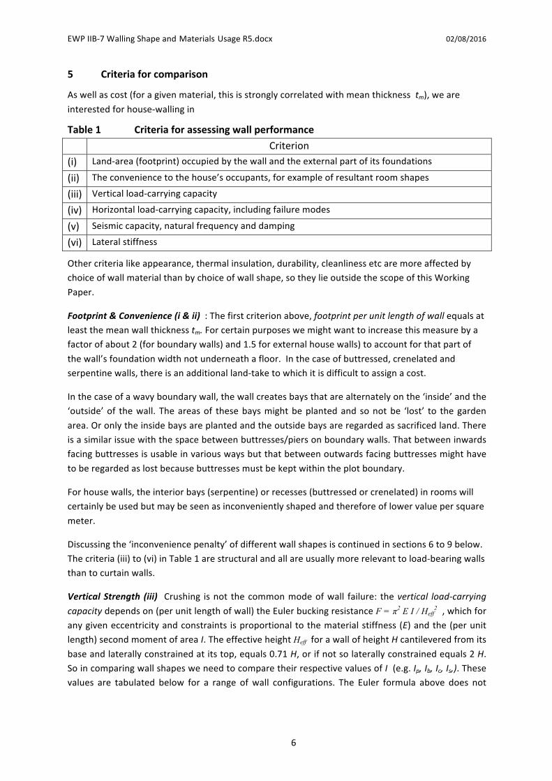
Table1 Criteriaforassessingwallperformance
Criterion
(i) Land-area(footprint)occupiedbythewallandtheexternalpartofitsfoundations
(ii) Theconveniencetothehouse’soccupants,forexampleofresultantroomshapes
(iii) Verticalload-carryingcapacity
(iv) Horizontalload-carryingcapacity,includingfailuremodes
(v) Seismiccapacity,naturalfrequencyanddamping
(vi) Lateralstiffness
Othercriterialikeappearance,thermalinsulation,durability,cleanlinessetcaremoreaffectedby
choiceofwallmaterialthanbychoiceofwallshape,sotheylieoutsidethescopeofthisWorking
Paper.
Footprint&Convenience(i&ii):Thefirstcriterionabove,footprintperunitlengthofwallequalsatleastthemeanwallthicknesstm.Forcertainpurposeswemightwanttoincreasethismeasurebya
factorofabout2(forboundarywalls)and1.5forexternalhousewalls)toaccountforthatpartof
thewall’sfoundationwidthnotunderneathafloor.Inthecaseofbuttressed,crenelatedandserpentinewalls,thereisanadditionalland-taketowhichitisdifficulttoassignacost.
Inthecaseofawavyboundarywall,thewallcreatesbaysthatarealternatelyonthe‘inside’andthe
‘outside’of thewall. Theareasof thesebaysmightbeplantedand sonotbe ‘lost’ to thegarden
area.Oronlytheinsidebaysareplantedandtheoutsidebaysareregardedassacrificedland.There
isasimilarissuewiththespacebetweenbuttresses/piersonboundarywalls.Thatbetweeninwards
facingbuttressesisusableinvariouswaysbutthatbetweenoutwardsfacingbuttressesmighthave
toberegardedaslostbecausebuttressesmustbekeptwithintheplotboundary.
Forhousewalls,theinteriorbays(serpentine)orrecesses(buttressedorcrenelated)inroomswill
certainlybeusedbutmaybeseenasinconvenientlyshapedandthereforeoflowervaluepersquare
meter.
Discussingthe‘inconveniencepenalty’ofdifferentwallshapesiscontinuedinsections6to9below.
Thecriteria(iii)to(vi)inTable1arestructuralandallareusuallymorerelevanttoload-bearingwalls
thantocurtainwalls.
VerticalStrength (iii) Crushing isnot thecommonmodeofwall failure: thevertical load-carryingcapacitydependson(perunitlengthofwall)theEulerbuckingresistanceF = π2 E I / Heff
2 ,whichforanygiveneccentricityandconstraints isproportionaltothematerialstiffness(E)andthe(perunitlength)secondmomentofareaI.TheeffectiveheightHeffforawallofheightHcantileveredfromits
baseandlaterallyconstrainedatitstop,equals0.71H,orifnotsolaterallyconstrainedequals2H.SoincomparingwallshapesweneedtocomparetheirrespectivevaluesofI(e.g.Ip,Ib,Ic,Is,).Thesevalues are tabulated below for a range ofwall configurations. The Euler formula above does not

EWPIIB-7WallingShapeandMaterialsUsageR5.docx 02/08/2016
7
apply to a wall buckling under its self-weight, which is however rarely the dominant failure
mechanism.
Horizontal load-carryingcapacity (iv), forexample themaximumacceptablewindpressureacting
on the whole wall face or top-edge lateral force (per unit of length) to overturn the wall, is
determined by the onset of tensile cracking in the wall-face to which the load is applied. Load
capacity depends on compensation by wall weight and on resistance due to the vertical tension
strengthofwall’smaterial.
The first factor,wallweight, causes a compressive pre-stress of σcomp = ρgH (whereH is thewallheight above the level chosen for analysis, g is gravity, ρ is wall density).H can be convenientlychosenastotalwallheight,sothattensileseparationisassumedtooccuratthebottomofthewall.
If thebrickwork is assumed tohaveno tensile strength, thenultimate failurewill occurwhen the
tensile stress in a wall face due to out-of-plane forces equals the pre-stress due to gravity. The
maximum tensile stress will be the overturning momentM (per unit length) at the chosen level
dividedby themodulusZ per unit length (Z = I/ymax). So the sustainablemoment isMg = σcompZHowever if thewallmaterialdoes have some tensile strength σtens then themoment that canbe
resisted is increasedby Mt=σtensZ,givingMfailure= (σtens+σcomp)Z. Ineithercase, thecomparative
abilitytoresistlateralforcesofdifferentwallshapesisproportionaltotheirrespectivevaluesofper
unitmodulusZ(namelyZp,Zb,Zc,Zs,)
Conventionalwallanalysisoftenrepresentstheeffectofgravitybyaverticalpressurepg,sothatatanychosenheighthwithinthewall,themomentthatcanbecarriedcanbewritten
M=pgZ where pg=ρg(H–h)forawallwith100%brick-to-brickcontact.
Ifhowever thebrick-to-brickcontactareaAc is less than thebrick’splanareaA, then the ‘gravity’equivalentpressureishigher: pg=(A/Ac)ρg(H–h).
orwherethewallalsohassometensilestrengthσtensand/orissubjecttopost-tensionofσpost-tens
M=(pg+σtens+σpost-tens)Z whereonlypgvarieswithpositionhupthewall.]
Earthquake resistance (v) is a complex phenomenon that depends on wall stiffness, internal
damping andother design parameters. It is therefore too extensive a topic to be covered by this
Paper.Howeverwenotethatitisgenerallylateralaccelerationthatdamageswallingduringtremors
and theeffectof suchaccelerations is similar towind loading.Thus seismicperformancedepends
upontheabilityofthewalltoresistlateralforces(justarguedtodependuponZ)andonthewall’smass,sincehorizontalseismicaccelerationsareconvertedintolateralforcesviathismass.Mass,for
agivenmaterialandwallheight,willbeproportionaltomeanwallthicknesstm.ThusresistancetoseismicfailureisproportionaltoZ/tm.
Lateralstiffness(vi)is,likeEulerload,proportionaltoEIor(forconstantE)justtotheperunit2ndmomentofareI.Formortaredwalls,lateralstiffnessisusuallyadequatetopreventanymalfunction
e.g. crackingof internalplaster.However forunmortaredwalls (of interlockingblocks), stiffness is
much lower. This may result in walls having too low a natural frequency and hence resonance
problemsduring‘quakes.

EWPIIB-7WallingShapeandMaterialsUsageR5.docx 02/08/2016
8
6 Plainwalls
Despite the bricks in a plane wall normally having no interlocks (although sometimes ‘frogs’ are
indentedtotheirtopsurfaces),themortarhassufficientshearbondingtothebrickstoholdthewall
together. This adhesion is enhanced by overlap between bricks on successive courses and the
avoidanceofcontinuousperplines.Forsinglethicknesswallsastretcherbondgives50%overlaps.
For double thickness a variety of bonds havebeendeveloped to give at least 25%overlapwithin
eachleafandtotiethetwoleavestogether.Single-thickness(e.g.100mm)planebrickwallsarenot
normally used for external house walling or for boundary walling. By contrast single-thickness is
normalforblockwalls(typically150mmthick)andmortaradhesionmaybeassistedbyinterlocking.
Doublingthethicknessofawallraisesitscrushingstrengthbyafactorx2,itsEulercollapseloadand
lateral stiffness by factor x8 (both being dependent on 2ndmoment I), and its lateral strength by
factorx4.
Verticalloadingisduetoself-weightandtheweightofsupportedupperfloorsandroof.
Lateralloadingarisesfrom:
windforces,whosepressurecentroidishalfwayupthewallandwhosemomentisgreatestatthe
wallbase,havingvalueMw=pressure.H2/2perunitlength;horizontalseismicaccelerationforces,whosecentreofaction ishalfwayupthewallandwhose
momentabove thewallbasehas thevalueMe=acceleration.ρgtmH2/2perunit lengthofwall,wheretmisthemeanwallthickness(againhingingisequallyprobableatallheights);
horizontallineforcestransmittedfromceilings(spanfloors)androof.Hinging/overturningdueto
anyof these forces isequallyprobableatallheights,as therestoringmomentduetowall
weightatanycourseisproportionaltothewallheightabovethatcourse.
7 Buttressedwalls
Abuttressedwall isshowninFig1c:theparticularexampledependsuponthebuttressdepthm-1(expressedas amultipleofbrickwidthW) and thebuttress spacingn (expressedas amultipleof
brick length L). Buttresses are also called piers, except that piers, like columns, can be inserted
symmetricallyinthewalllineandnotjusttooneside.‘Pier+Panel’isafurtherspecialcasewhere
onlythe(reinforced)pierhasfullfoundations.
Providedawallbehavesasalaterallyrigidcontinuum,thenthemeasuresofgreatestinteresttothe
structuraldesignerareits(mean)unitsecondmomentofareaIanditsmodulusZ.By‘unit’wemean
perunitlengthofwallingandby‘mean’thatthisisaveragedalongthelengthofthewall.Modulusis
notaveragedalong thewall, as itdependsupon themaximumdistance (ymax)on the tensionside
between the surface of thewall and thewall’s neutral axis. Since I riseswith the third power ofthickness, awallwithdeepbuttresseshasamuch larger stiffness thanonewith smallbuttresses.
Andofcoursemakingbuttressesmorefrequentalsomakesthewallstiffer.
Let I0 be theunit 2ndmomentofarea (unitsarem3)ofawallwithbuttresses spaced infinitely far
apart.Let Ibbe theunit2ndmomentofareaofabrickwallwithonebuttress (asinglebrickwide)
every n bricks of its length. Letm-1 be the depth of the buttress,measured in brick thicknesses
perpendicular to thewall’s face.Thus foraplanewall,m=0andmeanthickness= to.Whenm is
increasedornisdecreased,thestiffnessmeasureIb/I0increasesstrongly,thestrengthmeasureZ/Z0

EWPIIB-7WallingShapeandMaterialsUsageR5.docx 02/08/2016
9
increasesmoderatelyandthecostmeasuretb/t0 increasesweakly.Inthetables2to5thestiffnessandstrengthmeasuresrealsonormalisedtothenumberofbricksused.
Table2 Propertiesofbuttressedwalling
Walldepth/W=m 2 3 4 5
Spacing n in bricklengths
5 10 5 10 5 10 5 10
Stiffness & Euler
ratioIc/I03.2 2.2 10.3 6.3 24.4 14.8 47.1 28.8
StrengthratioZ/Z0 1.2 0.8 2.5 1.4 4.4 2.4 7.0 3.8
CostratioUb=tb/t0 1.2 1.1 1.4 1.2 1.6 1.3 1.8 1.4
Stiffness ratio per
brick(Ib/I0)/Ub
2.7 2.0 7.4 5.3 15.3 11.4 26.2 20.6
Strength ratio per
brick (also seismic
ratio)(Zc/Z0)/Ub
1.0 0.7 1.8 1.2 2.8 1.9 3.9 2.7
Sofor theexampleshadedabove,namelyaddinga3-brickbuttressevery10bricks,will increase Iand hence stiffness about 15 fold, Z and hence lateral strength (assuming force applied on the
buttressed side) about 2.4 fold, yet the number of bricks needed increases by only 30%. This
buttressspacing(10bricklengths)isapproximatelyequaltothelikelywallheightHforsingle-storeyhousing.
Howeverwallanalysisnormally takesaccountof thepositionofnotbuttressesbut ‘returns’ (well-
bondedperpendicularsupportwalls)assumedtobeinfinitelystrongandrigid.Yetwithsuchreturns
spacedclosely(spacingequalsapprox.thewallheight),thereturnsincreasethelateralpressureload
thewall’sweightcanresistonlybyafactorofabout3[Hendry,Fig7.6].Sinceabuttresshasrather
low stiffness, it is structurally worth less than a return. Therefore even a very deep buttress is
unlikelytoincreaselateralstrengthmorethan3-fold.
Abuttresshas tobondwith the restof thewall. The simplestbond (assuminga single-brickmain
wall)istohaveadoubleheaderonalternatecourses,ordiagonallyspacedsingleheadersonevery
course.Thisisnotastrongjointintension(wherewall-to-buttressforcesaretransmittedbybrick-
to-mortar-to-brick shear). If ¾ bricks are available, other bonds including those with double-
thicknesswallsarepossible.
Boundarywallsoftenfailbyexcessiveleaning,duetoveryslowsubsidenceundertheirfoundations,
rather than collapse under unusually high loading. (The bell tower of Pisa Cathedral is a famous
example, where leaning developed over eight centuries.) If buttresses are to resist this form of
failure their foundationsmust be substantial, rigid and if possible extend beyond their ends.One
methodofextending thesupport leverage (foranygivenbuttressvolume) is toemployslopingor
triangularbuttresses.Howeverasbuttressesareusuallyshort,theyhavepoorresistancetoracking
causedbyslidingatcourse joints.Suchsliding/shearing is reducedbyhavingmuchweightonthe
joints–whichpointstowardsusingfull-heightbuttresses.
Buttressesarethoughtto‘intrude’andarethereforeusuallyplacedontheoutsideofahousewall.
Placed internally they slightly reduce the flexibility of rooms, especially if their depth exceeds 0.3
meters(3bricks).Placedexternally,andwithfoundations,theydirectlyoccupyanextralandareaof

EWPIIB-7WallingShapeandMaterialsUsageR5.docx 02/08/2016
10
approximatelytwicetheirplanarea.Howeverifthehousewallisalsoontheplotboundarythenit
mayhavetobemovedinwardsbythebuttressdepth,therebylosingconsiderablymorelandarea.
8 Crenellatedwalls
Crenulation,seeFig1d,isameansofincreasingawall’seffectivethicknesswithoutusingmuchextra
material.Thecontributiontothewall’sI,byanyindividualbrick,riseswithapproximatelythesquare
ofthedisplacementofthatbrick’saxisfromthewall’saxis.Soacrenelatedwallwithlargesetbacks
hasamuchlargerstiffnessthanonewithasmallsetback.Wedefine‘set-back’asthedistancefrom
theaxisof its frontrowtotheaxisof itsbackrow(seeFig1c)andexpress itasamultiplem-1ofbrickthickness;D=mxWisthereforethedepthofthewall.
Table3 Propertiesofcrenellatedwalling
Walldepthm 2 3 4 5
Spacing n of set
backs(bricklengths)5 10 5 10 5 10 5 10
Stiffness & Euler
ratioIc/I04.8 4.4 15.8 14.4 35.2 31.6 64.0 56.6
StrengthratioZc/Z0 2.4 2.0 5.3 4.8 8.8 7.9 12.8 11.3
CostratioUc=tc/t0 1.2 1.1 1.4 1.2 1.6 1.3 1.8 1.4
Stiffness ratio per
brick(Ic/I0)/Uc
4.0 4.0 11.3 12.0 22.0 24.3 35.6 40.4
Strength ratio per
brick (also seismic
ratio)(Zc/Z0)/Uc
2.0 2.0 3.8 4.0 5.5 6.1 7.1 8.1
Again takingm = 4 i.e. (a setback-depth of 3W) andn = 10 (i.e. a setback-spacing of 10L) as ourexample,wenowhaveavery large increase in stiffnessandaquite large increase in strength for
onlyamodest (30%) increase inbrickuse. Moreover thesymmetricalnatureofacrenelatedwall
meanstheforwardandreversepropertiesarethesameaseachother.
Unlikewithbuttresses,thereisnoneedforaparticularlystifffoundationunderanypartofthewall.
Howevertheinconvenienceofthewallshape–itsimpactonroomusageandfurnishing-isgreater
thanforbuttressing.Indeedincountriesthatusedtohavecoalfireplacesineveryroom,theirdisuse
has led to the expensive demolition of ‘chimney breasts’, suggesting that residents found their
presence too intrusive. If the crenulations are ‘inwards’ from the external wall-line of a typical
house,andthereisonecrenulationperroom,theneachroomareaisreducedbytypically3%.For
boundarywallingthereislittlearealoss,sincethewall’sdirectfootprintislessthanthatofastraight
wall.Howevertheindividualrectangularbaysonboththeinsideandoutsidemayhavelittleutility
andcometobecountedaspartofthefootprint.
Constructionofastretcher-bondcrenelatedwallisstraightforward,usingclassiccornerbonds.The
possibilityofrackingishoweversignificant.Theconnectionbetweenthetwoleavesofacrenelated
wallcanalsobeareinforcedbrickpier,forexamplea300mmx300mmpierconnectingtwo100mm
wythes.

EWPIIB-7WallingShapeandMaterialsUsageR5.docx 02/08/2016
11
9 Wavy(serpentine)walls
Serpentinewalls are uncommon, although a number (under the name ‘crinkle-crankle wall’) that
were built over 200 years ago still survive in England, the Netherlands and USA. They achieve
effectivedepthviatheircurvature,notviatheadditionofextrabricks.Howevertheanglebetween
thebrick’s localaxisandthewall’saxisdoesnotusuallyexceed300,sotheiralong-the-wall length
andhencebrick-countiscommonlyonlyafewpercentmorethantheirlengthalongthewall’saxis.
Ifnormalstraightbricksareused, it isdesirablethattheanglebetweensuccessivebricksdoesnot
exceedabout90,otherwise thewallwill appear tooknobblywithbricksoverhanging thosebelow
thembyover2mm.Asinusoidalwallplanisprobablymostvisuallysatisfying.Howeveraserpentine
wallconstructedofalternatearcseachofconstantradiusRwillresultinalowermaximumcurvature
than a sinusoidal wall of the same depth and wavelength. Using such constant-curvature arcs is
normalpractice.
TheAmericanBrick Institute’stechnicalnotes(1982&1999)discusstheproportionsofserpentine
wallsthathaveshownverylong-termdurability.Thesearegenerallyverydeep,withdepthsnotless
thanhalfofwallheights.
Fig3 Serpentineboundarywallinseismiczone(FortPortal,Uganda2015)100mm-thick
Analysisoftheperunit2ndmomentofareaIandthemodulusZofserpentinewallsisdifficult,unless
werestrictourselvestocyclelengths(‘wavelengths’)correspondingtointegernumbersofbricksper
halfwave.
As for the otherwall types,we definem as the number of brickwidths thatmake up thewall’s
overalldepthDandnthenumberofbrickstomakeuptwoofthewall’sarcs(i.e.acompletecycle).
EWPIIB-7WallingShapeandMaterialsUsageR5.docx 02/08/2016
12
Table4 Propertiesofwavywalling
Recommended
Radiusofarc/t 13 40 10 20 6 15
Arc-angle/degrees 44 26 74 52 120 74
Maxangletowallaxis 22 13 37 26 60 37
Walldepth/W=m 3 5 7
Bricks/cycle=n 10 18 12 18 12 18
Wavelength/bricklength 10 18 11.2 17.5 10 16.7
Stiffness & Euler ratio
=Is/I07.1 7.5 25.8 26.2 57.6 57.3
StrengthratioZs/Z0 2.4 2.5 5.2 5.3 8.2 8.2
Costratious=ts/t0 1.03 1.01 1.07 1.03 1.21 1.07
Stiffness ratio per brick
=(Is/I0)/us6.9 7.4 24.1 25.4 47.6 53.6
Strength ratio per brick
(Zs/Z0)/us2.4 2.5 4.9 5.1 6.8 7.7
Angle between
successivebricks
8.80
2.90
12.30* 5.7
020.0
0*
8.30
Depth/wavelength 0.15 0.09 0.21 0.14 0.35 0.22
*unacceptablylarge
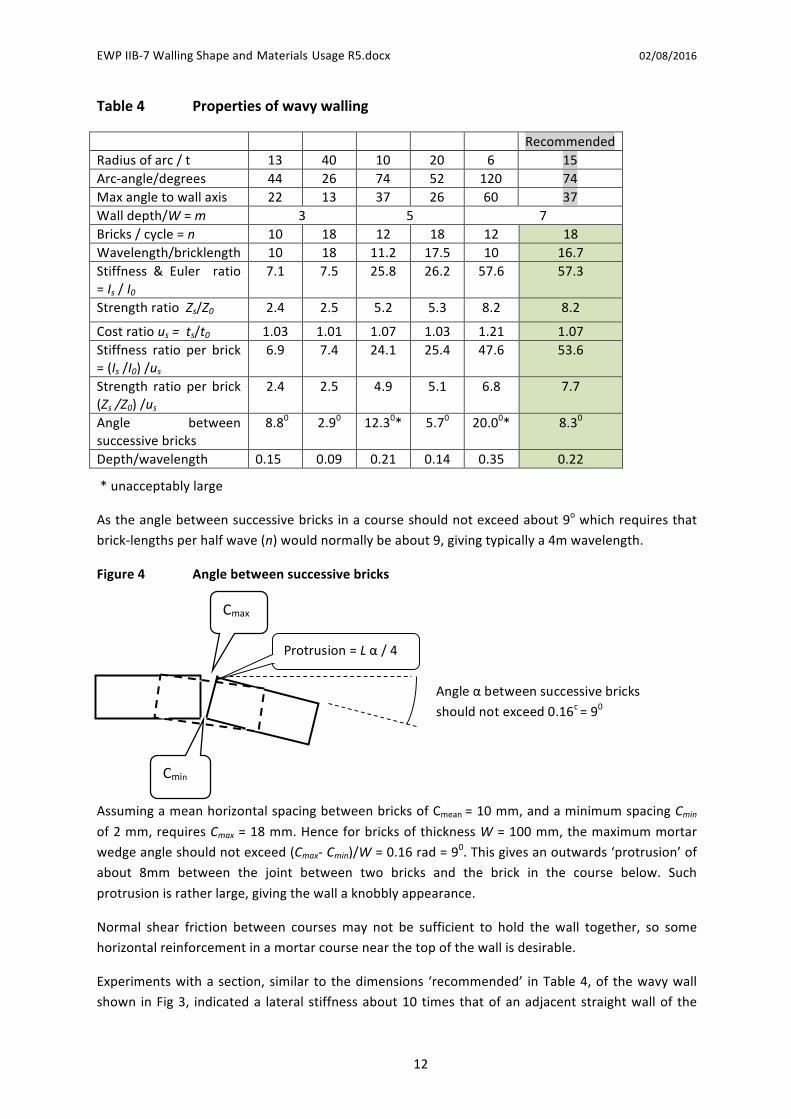
Astheanglebetweensuccessivebricksinacourseshouldnotexceedabout9owhichrequiresthat
brick-lengthsperhalfwave(n)wouldnormallybeabout9,givingtypicallya4mwavelength.
Figure4 Anglebetweensuccessivebricks
AssumingameanhorizontalspacingbetweenbricksofCmean=10mm,andaminimumspacingCmin
of2mm,requiresCmax=18mm.HenceforbricksofthicknessW=100mm,themaximummortar
wedgeangleshouldnotexceed(Cmax-Cmin)/W=0.16rad=90.Thisgivesanoutwards‘protrusion’ofabout 8mm between the joint between two bricks and the brick in the course below. Such
protrusionisratherlarge,givingthewallaknobblyappearance.
Normal shear friction between coursesmay not be sufficient to hold thewall together, so some
horizontalreinforcementinamortarcoursenearthetopofthewallisdesirable.
Experimentswithasection,similar to thedimensions ‘recommended’ inTable4,of thewavywall
shown inFig3, indicateda lateral stiffnessabout10 times thatofanadjacentstraightwallof the
Cmax
Angleαbetweensuccessivebricks
shouldnotexceed0.16c=9
0
Cmin
Protrusion=Lα/4

EWPIIB-7WallingShapeandMaterialsUsageR5.docx 02/08/2016
13
sameheight and thickness. This is less than the factorof around57 shown in the theory. Further
experimentswillbeperformed.
The brick count of a serpentinewall is low – often only a few percentmore than a single-wythe
planewall.Indeedthemainattractionofthewavywallshapeisthatitallowsalargeincreaseinits
effectivedepth (m) tobemadewithout significantly increasing itsuseofmaterials. So serpentine
wallsareusuallybuiltdeeperthancrenelatedwalls;e.g.forthecasem=7,shownhighlitinTable3
above,thedistancefromfrontfacetobackfacewouldbe70cm(ifbricksare10cmwide).If,fora
boundarywall,thewholeserpentinemustlieinsidetheplotboundary,thenthereissignificantextraland-take,about50%ofwhichiseffectivelydonatedtotheneighbouringplot.Ifhoweverthewall’s
axis lies along the plot boundary, then both this and the neighbouring plot experience alternateintrusionandretreat(bays).
Exampleofasimplehouseplanwith
serpentineexteriorwallsand
straightinternalwalls.
10 Numericalcomparisonsofthe4wallplans
Wecannowcompare(Table5)the4shapevariants–plane,buttressed,crenelatedandserpentine.
Table5 Comparisonofwallshapes(m=D/W=3shownshaded).
Wallshape Plain Buttressed
every5bricks
(n=5)
Crenulated
every5bricks
(n=5)
Wavy
wavelength
(n=18)
Wall-depthm 1 2 3 2 3 5 2 3 5 3 5 7
Costratious=ts/t0 1 2 3
1.2 1.4
1.8 1.2 1.42
1.8 1.01
1.03 1.07
Stiffnessratio(I/I0) 1 8
27 3.2 10.3+
47.1 4.8+
15.8+
64.0 7.5+
26.2 57.3
Strengthratio(Z/Z0) 1 4* 9
1.2 2.5*
7.0* 2.4* 5.3* 12.8 2.5*
5.3* 8.2
(Is/I0)/us 1 4 9
2.7 7.4
26.2 4.0 11.3 35.6 7.4
25.4 53.6
(Zs/Z0)/us 1 2 3
1.0 1.8
3.9 2.0 3.8
7.1 2.5
5.1 7.7
Notes:Stiffness-ratio/cost-ratio=(Zs/Z0)/usisalsotheseismicaccelerationtoleranceratio
Wavywallwavelengthislong(n=18),elsethebrick-to-brickanglewouldbetoohighForplainwallsm=2iscommonlyused–asshownbyboldproperties
Tosimplifythiscomparisonletusfirst lookatthecasem=3, i.e.wherethewalldepthD,fronttoback,is3timesabrickthickness.Inthetable,thedatacolumnsforthiscasearehigh-lit.
Intermsofcost,foragivenlengthofwallandwalldepthm=3,theorderis:
wavy(best),crenelated,buttressed,plane(muchtheworst).
Intermsofperformanceasmeasuredby2ndmomentIandsectionmodulusK,theorderis:
plane/crenelated(good),buttressed/wavy(poor).
If we combine performance and cost by expressing performance per brick used, we get:
crenelated(best),plane,wavy,buttressed(worst).

EWPIIB-7WallingShapeandMaterialsUsageR5.docx 02/08/2016
14
If however we had taken amore typical 2-brick (m=2) plain wall as our datum, then the
‘performanceperbrick’testwouldhaverankedtheoptions:
crenelated(best),wavy,plane,buttressed(worst)
Adifferentandmorerealisticapproachistofirstdefineaperformanceandthenassessthematerials
costofmeetingit,usingeachofthefourwallshapes.Thuschoosing(forconvenience)aresistance
tooverturning forces equal to thatof a double-thickness (m = 2) planewall, forwhichZ/Z0 = 4,where Z0 is the modulus of our datum single-wythe plain wall. We get, approximately, by
interpolation(ofcandidatesmarked*inTable5),theoptionsof:
abuttressedwall,withm=4,n=5,costing20%lessthantheplanewall
acrenelatedwall,withm=3,n=5,costing30%less
awavywall,withm=4,n=18,costingnearly50%less
Applyingthesameapproachtogettingastiffness(andalsoquakeresistanceandEulerbucklingload)equal to that of the double (m=2) plane wall, we could use (candidates with I/I0 = approx 8, asmarked
+inTable5):
abuttressedwall,withm=3,n=5,costing30%lessthantheplanewall;
acrenelatedwall,withm=2.5,n=5,costing35%less;
awavywall,m=3,n=18,costing50%less.
Ingeneral therefore,buttressing isnotaveryefficientuseofbrick,whereasbothcrenulationand
employingwavywallingoffersubstantialsavings.Themainpricetopayforthissavingisthepossible
inconvenienceofhavingsteppedorcurvingsurfaces inaroomor losinga littleplotareanexttoa
boundarywall.
10 Conclusions
Crenelatedandwavywallsuseupto50%lessbricksthanplanewallstoachievethesameresistance
tobuckling,samestiffnessandsameresistancetolateralforces.Buttressedwallsareintermediate
intermsofbrickeconomy.Indeedthesedesignscanbeusedwithasinglebrickthickness(e.g.100
mm) to get satisfactory performance in both housing and boundarywalls; by contrastwith plane
wallingadoublethickness(e.g.200mm)isnormallyrequired..
Bothcrenelatedandwavydesignsare suitable for increasing strengthandstiffnessbymaking the
walldeeperyetwithoutusingmanymorebricks.Theshapeofthesematerially-efficientwallplans
mayconflictwiththerectangularnormofmostmodernbuildings.Conversely theyofferscopefor
architecturaldistinctiveness.
Thesimplifiedanalysisusedinthispaperassumesthatduringloading,thewallsholdtogetherand
actasawhole.Rackingduetoslippagebetweencourseshasthereforenotbeenconsidered.These
assumptionsmayproveunfoundedinthecaseofverydeepcrenelatedorserpentinewalls–e.g.m
valuesexceedingsay5.
11 Bibliography
HendryAW,SinhaBP,DaviesSR,1997,DesignofMasonryStructures,3rdEd,E&FNSpon
BSEN1996-3:Simplifiedcalculationmethodsforunreinforcedmasonrystructures

EWPIIB-7WallingShapeandMaterialsUsageR5.docx 02/08/2016
15
http://en.wikipedia.org/wiki/Crinkle_crankle_wall,2014
BIA,1982,Structuraldesignofserpentinewalls–non-loadbearing,TN33,Renton,VA,USA
BIA,1999,BrickinLandscapeArchitecture-GardenWalls,TN29A,Renton,VA,USA
Photosofwavywalling:
http://www.geograph.org.uk/gallery/crinkle_crankle_or_serpentine_walls_15374,acc’dDec2016

EWPIIB-7WallingShapeandMaterialsUsageR5.docx 02/08/2016
16
Appendix
Calculations for Constant Radius Wavy Walls Assume wall is a sequence of 'facing' arcs each of radius R, arc angle 2θ, and thickness t, where R = λt 2nd moment of wavy wall is μ times that of a straight wall of thickness t and of the same 'axial' length; . I = µ Io However as the curved wall is slightly longer (for the same axial length), we have a brick usage multiplier of σ = θ/sin(θ) Depth, front-face to back-face of wall , D = t + 2*R*(1-cos(θ)); datum wall depth = t; relative depth is m = D/t m = 1 + 2*λ*(1-cos(θ)) where λ = R/t Relative stiffness μ = (θ/sin(θ))*{1+6λ^2(1 - 3(sin(θ)*cos(θ)/θ) + 2cos^2(θ)} μ = σ*(1+6λ^2*e)
where e = (1 - 3(sin(θ)*cos(θ)/θ) + 2cos^2(θ)
As a close
approximation μ = μ' = 1+1.59*(m-1)^2
Relative stiffness per brick used is μ / σ = 1+6λ^2*e
I / Io relative relative relative
wall radius half stiffness brick stiffness Wall relative Wave depth/ thickness R/t arc angle per meter usage per brick depth strength length wavelth
t R λ θ θ e μ σ μ / σ D m μ / m W D / W μ'/μ
m m rads degree m d / t
0.1 0.6 6 1.05 60 0.2620 57.6 1.21 47.6 0.70 7.0 8.19 2.08 0.34 0.979
0.1 1 10 1.571 90 1.0004 601.2 1.57 382.7 2.10 21.0 28.62 4.00 0.53 semicircs 0.943 0.1 1 10 0.785 45 0.0900 55.0 1.11 49.5 0.69 6.9 8.02 2.83 0.24 1/4 circles 0.991
0.1 1 10 0.523 30 0.0189 12.4 1.05 11.8 0.37 3.7 3.36 2.00 0.18 1/6 circs 1.000
0.1 5 50 0.1 6 0.0000 1.4 1.00 1.4 0.15 1.5 0.93 2.00 0.08 1.002
0.1 5 50 0.2 11 0.0004 7.4 1.01 7.3 0.30 3.0 2.46 3.97 0.08 1.005 0.1 5 50 0.284 16 0.0017 26.6 1.01 26.3 0.50 5.0 5.32 5.60 0.09 1.004 0.1 5 50 0.3 17 0.0021 32.8 1.02 32.4 0.55 5.5 6.01 5.91 0.09 1.004 0.1 5 50 0.4 23 0.0066 100.3 1.03 97.7 0.89 8.9 11.28 7.79 0.11 1.002 0.1 5 50 0.6 34 0.0323 484.9 1.06 456.3 1.85 18.5 26.26 11.29 0.16 0.998
0.1 2.5 25 0.1 6 0.0000 1.1 1.00 1.1 0.12 1.2 0.88 1.00 0.13 1.001 0.1 2.5 25 0.2 11 0.0004 2.6 1.01 2.6 0.20 2.0 1.30 1.99 0.10 1.003 0.1 2.5 25 0.3 17 0.0021 9.0 1.02 8.8 0.32 3.2 2.77 2.96 0.11 1.004 0.1 2.5 25 0.4 23 0.0066 25.8 1.03 25.1 0.49 4.9 5.22 3.89 0.13 1.002 0.1 2.5 25 0.523 30 0.0189 72.0 1.05 68.8 0.77 7.7 9.37 4.99 0.15 1/6 circs 1.000 0.1 2.5 25 0.6 34 0.0323 122.0 1.06 114.8 0.97 9.7 12.53 5.65 0.17 0.998

EWPIIB-7WallingShapeandMaterialsUsageR5.docx 02/08/2016
17