Embed Size (px)
Citation preview

Evolv DNA 250 Color
400 Watt Variable Power Module with Temperature Protection, Replay, and USB
The DNA 250C is a power regulated digital switch-mode DC-DC converter for personal vaporizers. It features Evolv’s patented Wattage Control, Temperature Protection, Replay, Preheat, full color TFT screen, USB On-The-Go, Reverse Polarity Protection, an onboard programmable multicolor LED, waterproof onboard buttons, and a real-time clock. Evolv’s EScribe software and Theme Designer software can be used to fully customize all aspects of the interface and monitor the user experience. The DNA 250C runs on two, three, or four series voltage from lithium polymer or lithium ion batteries, and features battery monitoring and an integrated 2A charger.

Operating Range Minimum Typical Max Peak Output Power 1 Watt 400 Watts Output Voltage .2 Volts 10.0 Volts Output Current .5 Amps 65.0 Amps 70.0 Amps Atomizer Resistance, temperature sensing wire, cold
See Graph .15 Ohm See Graph
Atomizer Resistance, Kanthal wire See Graph .25 Ohm See Graph Atomizer Resistance, cold .02 Ohm 8.0 Ohm Temperature Limit 200°F 450°F 600°F Input Voltage, unloaded 6.0 Volts 14.8 Volts 16.8 Volts Input Current 12.0 Amps 30.0 Amps 32.0 Amps Screen On Current 21mA Quiescent Current 10mA Power Down Current 20uA Efficiency 98%
Specifications Footprint .79” x 2.75” / 20mm x 70mm Thickness .33” / 8.5mm Screen .9” 80 x 160 pixel Full Color TFT Weight 15.85g

Contents Operating Range ........................................................................................................................................... 2
Temperature Protection ............................................................................................................................... 4
Replay ........................................................................................................................................................ 5
Preheat ...................................................................................................................................................... 5
Boost ......................................................................................................................................................... 5
Attaching a New Atomizer ........................................................................................................................ 5
Output Power ................................................................................................................................................ 6
Display ..................................................................................................................................................... 10
Error Messages ....................................................................................................................................... 10
Charger ........................................................................................................................................................ 11
Cell-by-cell Monitoring............................................................................................................................ 11
Cell Balancer............................................................................................................................................ 11
USB On-The-Go ....................................................................................................................................... 11
Fuse ............................................................................................................................................................. 12
Escribe ......................................................................................................................................................... 12
Pinout (bottom side shown) ....................................................................................................................... 13
Wiring .......................................................................................................................................................... 14
Recommended wire sizes ....................................................................................................................... 14
2s Wiring ................................................................................................................................................. 14
3s Wiring ................................................................................................................................................. 15
4s Wiring ................................................................................................................................................. 16
Reverse Polarity Protection .................................................................................................................... 17
External component recommendations ................................................................................................. 17
Assembly ..................................................................................................................................................... 18
Installing the Balance Connector ............................................................................................................ 18
Installing the Screen ................................................................................................................................ 19
Mounting..................................................................................................................................................... 20
Mechanical Dimensions .............................................................................................................................. 21
Temperature Protection1 The DNA 250C directly measures and limits the temperature of the heating coil during
operation. By preventing the coil from becoming too hot regardless of fluid, wicking or airflow, a variety of undesirable situations can be prevented. For example, appropriate temperature settings will prevent the wicking material from charring, which compromises taste and introduces unintended chemicals into the vapor. Appropriate temperature settings will also reduce the breakdown of flavoring and base liquid components, which could impact taste or safety.
Evolv’s Temperature Protection Technology requires a heating coil made from Nickel 200 alloy or other materials with a well-defined temperature coefficient of resistance, rather than Nickel Chromium or Kanthal alloys. If the temperature reaches the maximum value, the wattage applied to the atomizer coil is reduced to prevent overheating. Please note that the temperature reading is the average temperature of the atomizer coil, and care should be taken to construct the heating coil so that the temperature is uniform, without hot or cold spots.
Because wattage, not temperature, controls vapor volume, large vapor volumes can be produced without unnecessarily high temperatures. Temperature Protection is most helpful if the atomizer begins to dry out, the user pauses during a puff, the beginning or end of the puff, or if the wattage setting is inappropriate for the attached atomizer.
In normal operation, when the device is not firing the maximum temperature setting is displayed on the screen.
By default, the Temperature Protection setting is 450° Fahrenheit. To change the limit on the default interface:
1) Using the up and down buttons highlight the temperature value.
2) Press the select button.
3) Using the up and down buttons adjust the temperature to the desired value and press the select button to confirm.
4) Use the up and down buttons to adjust the maximum temperature
5) When the display shows the desired maximum temperature, press the Fire button to exit temperature adjust mode.
The maximum temperature is adjustable between 200° Fahrenheit and 600° Fahrenheit. To disable the temperature protection entirely, change to a profile that does not support temperature protection such as the ‘Watts’ profile.
1 Please note all instructions in this document reference the default Evolv theme. Interface design may vary between devices and manufacturers.

Replay Replay is a new feature introduced on the DNA 250C. Replay is intended to capture the flavor and satisfaction of the “perfect puff” and provide the same level of performance and consistency on all subsequent puffs. The use of Nickel, Stainless, Titanium, or other material that increases in resistance when heated is required. In addition, Replay will also prevent dry hits when used with wattage control.
To use Replay set the device to the desired power level and operate it normally. Once a satisfying puff is achieved, activate the feature to save and replay the saved puff each time the device is fired. Puff length is not a factor and the user will not be limited to the length of the previous puff. Disable Replay to resume normal operation or find a new puff to save. If Replay cannot be enabled the coil is not compatible.
Preheat When the DNA 250C is used with a temperature sensing atomizer, an additional feature called
Preheat is activated. No vapor is produced when the temperature is below the boiling point of the liquid. Preheat applies extra power until the heating coil is up to operating temperature to shorten the delay between pressing the fire button and generating vapor. Because preheat is temperature based, it will not overheat or burn the vapor. The Preheat settings can be adjusted from the device.
Boost The DNA 250C supports Boost functionality when not used with a temperature sensing atomizer
to briefly increase the initial power output at the start of a puff. This can be useful to allow higher mass coils to reach the point where they produce vapor quicker. Boost can be toggled on or off from the device. The Boost value is adjustable from 1 to 11 with a higher value giving a stronger Boost.
Attaching a New Atomizer The DNA 250C uses the resistance of the atomizer to calculate the temperature of the heating
coil. It continually looks to see whether a new or changed atomizer has been connected. If you are using temperature protection, be careful to only attach new atomizers that have cooled to room temperature. If a new atomizer is attached to the DNA 250C before it has cooled down, the temperature may read and protect incorrectly until the new atomizer cools.
When you connect a new atomizer or disconnect and reconnect your existing atomizer, the DNA
250C will prompt you to confirm this change. When you fire the first time, before activating the DNA 250C will display the ‘New Coil’ screen. When you see this screen, if you have attached a new atomizer, highlight the ‘Yes’ option and press the select button to confirm. If you have disconnected and reconnected the same atomizer, highlight the ‘No’ option and press the select button to confirm. If you believe the sample resistance shown is incorrect you may highlight and select ‘Measure Again’ to take another resistance reading.

Output Power The following graphs show the output power range of the DNA 250C for the various cell configurations as a function of the coil resistance.
2s Output Power

3s Output Power

3s Output Power (International)

4s Output Power

Display The DNA 250C has a full color 80 x 160 pixel TFT screen. The screen is attached to the main
board by a flexible cable, allowing freedom in the design of your device. The screen’s default position is on top of the board, between the fire and adjust buttons. This allows for easy assembly. The screen connects to the board with a ZIF connector, so alternate placement is possible. Please use caution when handling the screen and design the device so that the cable will be secured or strain relieved in operation. The two notches along each side of the PCB are designed to accommodate a screen holder. A 3D model is available to 3D print or injection mold screen holders for the DNA 250C.
When installing the screen connector into the ZIF connector care should be taken to not bend the cable or apply excessive force when inserted. A sharp right angle bend in the cable can ruin the screen and break the connections in the ribbon cable. The proper way to install the screen is to firmly grasp the ribbon with a pair of tweezers and slide it directly into the connector without bending the cable.
Error Messages The DNA 250C will indicate a variety of error states.
No Atomizer: The DNA does not detect an atomizer.
Check Atomizer: The DNA has detected a large resistance change during operation, the atomizer has shorted out, or the atomizer resistance is incorrect for the power setting.
Check Battery: The battery is deeply discharged and needs to be charged, or is damaged. If this happens, the DNA 250C will not fire the atomizer. The Check Battery message will continue to display for a few seconds after attempting to fire the device. User should remove and replace the battery.
Shorted: The atomizer or wiring are short circuited.
Ohms Too Low: The resistance of the atomizer coil is too low for the current wattage setting. If this happens, the DNA 250C will continue to fire, but will not be able to provide the desired wattage. The Ohms Too Low message will continue to display for a few seconds after the end of puff.
Ohms Too High: The resistance of the atomizer coil is too high for the current wattage setting. If this happens, the DNA 250C will continue to fire, but will not be able to provide the desired wattage. The Ohms Too High message will continue to display for a few seconds after the end of puff.
Temperature Protected: The heating coil reached the maximum allowed temperature during the puff. If this happens, the DNA 250C will continue to fire, but will not be able to provide the desired wattage.
Weak Battery: The battery needs to be charged, or a higher amp rated battery needs to be used. If this happens, the DNA 250C will continue to fire the atomizer, but will not be able to provide the desired wattage. The Weak Battery message will continue to display for a few seconds after the end of the puff.

Return To Researcher: The DNA has reached a limit configured by a researcher. Contact the research institution that issued the device.
Too Hot: The DNA 250C has onboard temperature sensing. It will shut down and display this message if the internal board temperature becomes excessive.
Charger The DNA 250C has a built in 2A USB charger. It automatically detects the type of USB power
supply it is connected to, so it can be plugged into standard PC USB ports or higher power chargers. The max charge current is based on the cell capacity as programmed in EScribe.
Cell-by-cell Monitoring The DNA 250C runs from up to a four cell battery. Because lithium polymer cells can be
damaged by excessive discharge, with multi-cell series batteries it is important to measure each cell in the battery independently and stop firing the atomizer when any of the cells reaches the cutoff voltage. The DNA 250C uses the battery pack taps to monitor each cell.
Cell Balancer During charging, it is vital that none of the batteries charge beyond 4.2 volts per cell. If one of
the cells in the battery has more charge than the others, its voltage will be higher. During charging, the DNA 250C will turn on a “balancer” to charge that cell more slowly, allowing the less charged cells to catch up.
By monitoring and charging each cell individually, the safety of a multi-cell pack is equivalent to
using a single cell. Many products, from power tools to laptops to electric vehicles, use multi-cell packs. All responsible multi-cell lithium based designs use cell by cell monitoring and balancing to operate safely.
USB On-The-Go The DNA 250C supports USB On-The-Go. An OTG adapter may be plugged into the Micro USB
port on the device to charge any other device capable of charging via USB. By default OTG charging must be toggled on manually from the device. OTG charging can be configured to begin automatically using the Power Bank option in EScribe on the Display tab. OTG charging will not over-drain the DNA 250C.
Fuse Because of the energy and power stored in the battery, the DNA 250C includes an onboard 30
amp SMT fuse. The fuse is located on the underside of the PCB near the B+ battery terminal, and is labelled “Fuse”. In normal operation the fuse should never blow. However, in the event of an error or short circuit on the board, the fuse will protect the battery. Should it need to be replaced, the fuse is manufactured by Bel Power Solutions, part number C1H30.
If you suspect your fuse is blown, check continuity across the fuse to verify using a Multimeter.
Replacement is accomplished by de-soldering the blown fuse from the board and soldering on a new fuse.
DNA 250C is designed for battery packs that are permanently installed into the device, or battery packs that install using an insulated, polarized connector rated for at least 30 amps. If the battery pack is installed with the polarity reversed, the fuse will blow to protect the battery pack, board and user.
If you are manufacturing a device that is designed to be used with individual replaceable 18650
cells, the DNA250C offers reverse polarity protection.
Escribe Escribe is a software package used to configure, monitor and modify the operation of your DNA
250C. It installs on a Windows or Mac computer and connects to your DNA 250C using the USB port. Escribe has a separate manual and tutorials which can be found on Evolv’s site.
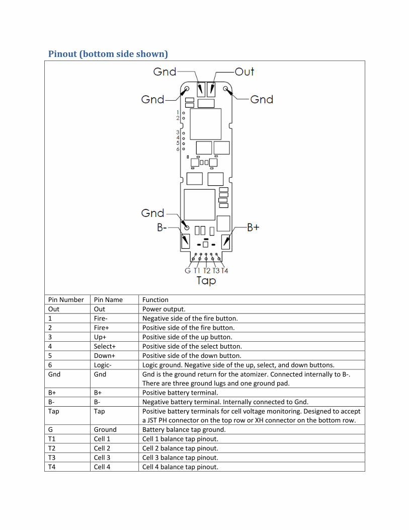
Pinout (bottom side shown)
Pin Number Pin Name Function Out Out Power output. 1 Fire- Negative side of the fire button. 2 Fire+ Positive side of the fire button. 3 Up+ Positive side of the up button. 4 Select+ Positive side of the select button. 5 Down+ Positive side of the down button. 6 Logic- Logic ground. Negative side of the up, select, and down buttons. Gnd Gnd Gnd is the ground return for the atomizer. Connected internally to B-.
There are three ground lugs and one ground pad. B+ B+ Positive battery terminal. B- B- Negative battery terminal. Internally connected to Gnd. Tap Tap Positive battery terminals for cell voltage monitoring. Designed to accept
a JST PH connector on the top row or XH connector on the bottom row. G Ground Battery balance tap ground. T1 Cell 1 Cell 1 balance tap pinout. T2 Cell 2 Cell 2 balance tap pinout. T3 Cell 3 Cell 3 balance tap pinout. T4 Cell 4 Cell 4 balance tap pinout.

Wiring The atomizer is connected to the Out pad. If the DNA 250C is not being grounded through the
mounting screws, the Gnd pad should connect to the negative side of the 510 connector. The battery is connected to the B+ and B- terminals. It is important to use appropriately sized wire when using the DNA 250C. Too small wire will not perform well, and significantly undersized wire can burn out. The output wires should be silicone or Teflon insulated only, and at least 12 gauge if used in a 4s device. The input wire carries less current, and can be as small as 20 gauge wire if silicone or Teflon insulated.
Recommended wire sizes Minimum size Recommended size Maximum size Battery, silicone insulated 20 gauge 18 gauge 14 gauge Battery, PVC insulated 18 gauge 16 gauge 14 gauge Output, silicone insulated 14 gauge 12 gauge 12 gauge Switches, if used 28 gauge 24 gauge 22 gauge Battery tap, silicone insulated 26 gauge 24 gauge 22 gauge
2s Wiring

3s Wiring

4s Wiring
Reverse Polarity Protection The DNA 250C includes built in Reverse Polarity Protection to protect the user, board, device,
and battery in the event that a battery is inserted backwards.
External component recommendations The DNA 250C is a self-contained power regulator which does not require external buttons for
its user interface. However, it does support the use of external buttons if desired.
Fire button:
Use a momentary on, normally open type switch or button. A standard pushbutton switch is appropriate. The switch is a logic function – all power switching is handled with transistors inside the DNA module, so the switch does not need to be rated for power. A waterproof or processed sealed switch is recommended. Please use caution, as the positive side of the fire button connects directly to positive battery voltage.
Up/Select/Down buttons:
The small onboard buttons allow the user to navigate the interface and modify device settings. Alternatively, remote normally open type switches or buttons can be attached to the UP, SELECT and DOWN mounting holes for customization.
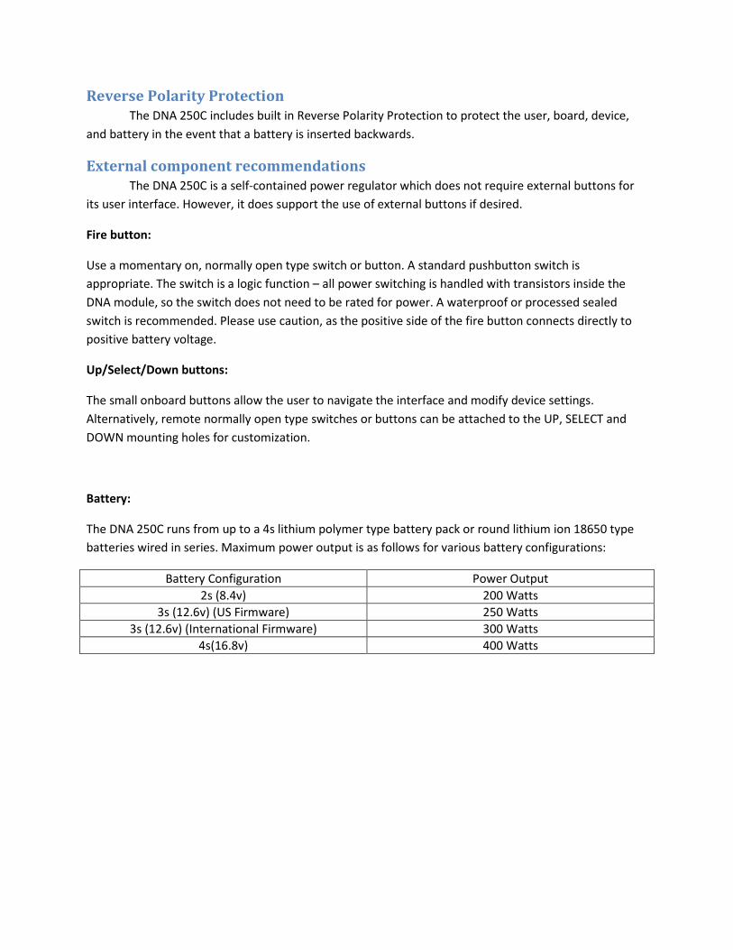
Battery:
The DNA 250C runs from up to a 4s lithium polymer type battery pack or round lithium ion 18650 type batteries wired in series. Maximum power output is as follows for various battery configurations:
Battery Configuration Power Output 2s (8.4v) 200 Watts
3s (12.6v) (US Firmware) 250 Watts 3s (12.6v) (International Firmware) 300 Watts
4s(16.8v) 400 Watts

Assembly
Installing the Balance Connector Step 1: Locate the balance connector in your packaging. The DNA 250C includes a 5 pin JST XH connector. The balance connectors intended for use are made by JST and are the XH and PH Connectors. Compatible part numbers are B5B-XH-A and PHR-5. Ensure that the battery to be used has a matching XH or PH series connector. If it does not, procure an appropriate connector for the board or battery pack. Due to the design of the balance tap area Evolv recommends only installing balance connectors via the through holes.
Step 2: The balance connectors are inserted in the appropriate holes on the back side of the board opposite the buttons and soldered in place. PH connectors will fit the row closest to the USB connection and XH series connectors will fit the row furthest from the USB connection.
JST PH Connector JST XH Connector

Installing the Screen The TFT screen connects to the DNA 250C using an 8 pin ZIF socket and a flexible cable to allow for design flexibility. The cable can be bent or folded (once) but care should be taken to not apply tension or strain to the area where the cable attaches to the screen itself. Once the screen is mounted the cable should be tucked up under the screen and not out towards the fire button. Positioning the cable near the fire button can allow the mods fire button to contact the cable when pressed which will cause eventual screen failure. Only insert or remove the screen before the board is powered on.
Step 1: Locate the ZIF connector on the DNA 250C PCB.
Step 2: Carefully and gently lift the locking tab on the rear of the connector to vertical.
Step 3: Fully insert the flexible cable into the front of the socket with the contact side towards the PCB. Do not bend the end of the cable at a right angle and force it into the ZIF socket. Grasp the cable with a pair of ESD tweezers and slide it directly into the ZIF socket.
Step 4: Close the locking tab and press until the connector gently clicks. Remove the clear screen protector by pulling on the colored tab.

Screen issues can occur if the screen is inserted incorrectly. If you are experiencing a white screen or intermittent display issues confirm the screen is correctly seated in the ZIF socket as shown below.
Mounting The DNA 250C has onboard switches for adjusting the power level, navigating the interface and activating the output. Each of these functions also has optional through-hole pads for using remote buttons.
The DNA 250C has three mounting holes on the PCB. These holes are designed for #0 screws. There is an extended mounting pad of .125” diameter around each. These holes are electrically connected to each other and to ground. With careful design, the mounting pads can be used to ground the chassis to the DNA 250C and pass the output current through chassis to the connector. However, if using this method, ensure that the PCB remains in good contact with the chassis at all times. Split lock washers and a RoHS chromate conversion coating on the chassis are recommended.
It is recommended that DNA boards be secured using the provided holes to mechanically mount them to the device. Use of glues are not suggested including hot glue, epoxy, superglue, hobby cement, etc. The only adhesive approved for contact with the board is non-corrosive Silicone adhesive such as the kind available from MG Chemicals.
DNA boards are complex, utilizing multilayer PCBs, and are designed with safety and reliability in mind. Please do not modify components on the boards, remove onboard buttons, shave, cut or trim the PCB or enlarge the mounting holes. Doing so creates the potential to expose layers in the PCB and could cause a safety and/or reliability issue.
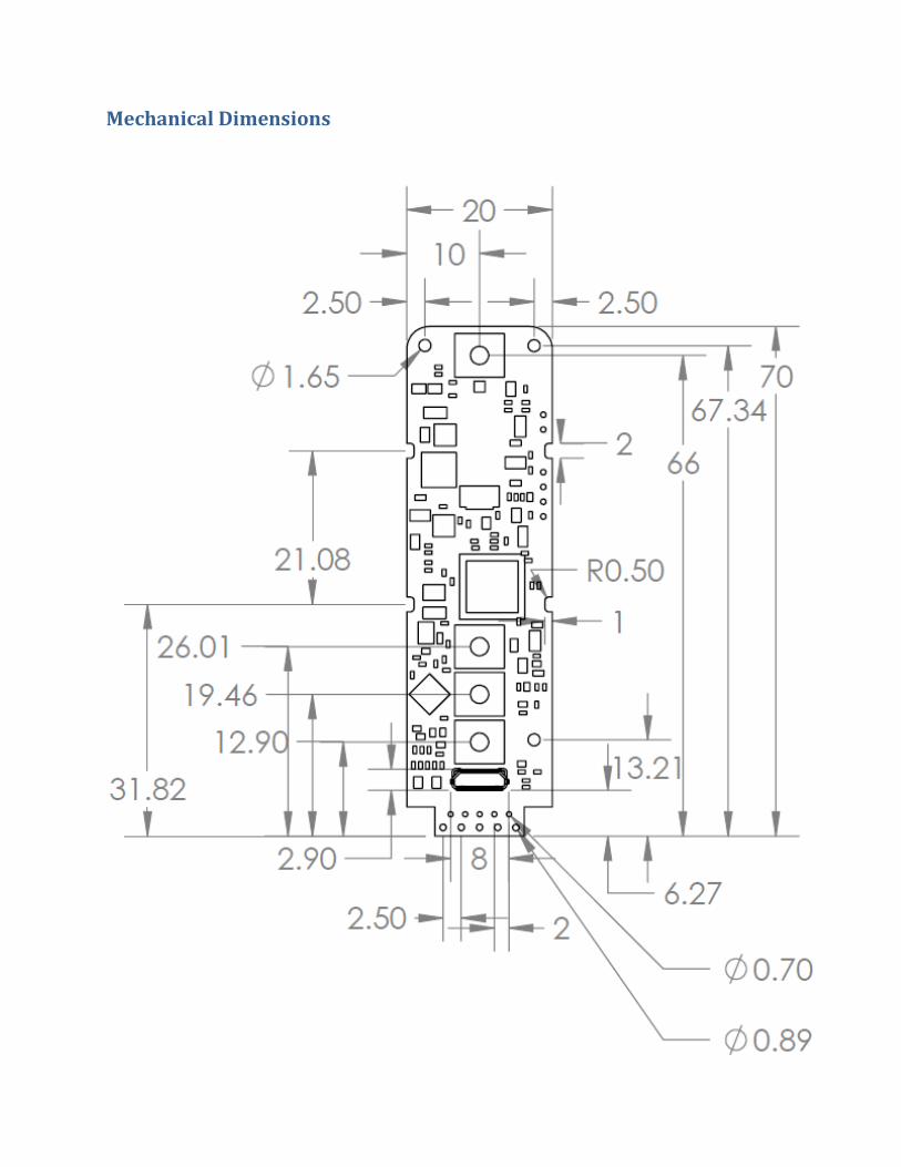
Mechanical Dimensions


3D models of the DNA 250C available on our website in IGES, STEP, and Solidworks formats.