Embed Size (px)
Citation preview
2333-1
Workshop on Science Applications of GNSS in Developing Countries (11-27 April), followed by the:
Seminar on Development and Use of the Ionospheric NeQuick Model (30 April-1 May)
A. J. Van Dierendonck
11 April - 1 May, 2012
AJ Systems/GPS Silicon Valley USA
Evolution to Modernized GNSS Ionospheric Scintillation and TEC Monitoring

4/18/2012 African Workshop 2012 1
Evolution to Modernized GNSS
Ionospheric Scintillation and TEC
Monitoring
Dr. A.J. Van Dierendonck, AJ Systems
4/18/2012 African Workshop 2012 2
Tutorial Outline
Short Review of GPS Receivers Emphasizing what functions are affected by scintillation Emphasizing modifications implemented for measuring scintillation effects
Amplitude and Phase Scintillation Measurements Measurement Limitations
How well does the receiver perform in a scintillation environment? How can a GNSS receiver be designed to better operate in a scintillation environment?
TEC Measurements Measuring TEC or satellite and/or receiver inter-frequency biases?
Example Measurements GPS Satellites SBAS Geostationary Satellites

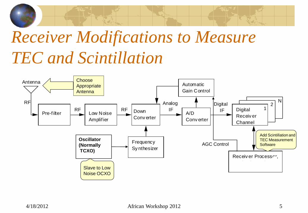
Multiple Frequency GNSS Receiver
Functional Block Diagram
4/18/2012 African Workshop 2012 3
Pre-f ilter Low Noise
Amplif ier
Down
Conv erterA/D
Conv erter
Frequency
Sy nthesizer
Automatic
Gain Control
Digital
Receiv er
Channel
1
N2
Receiv er Processor,
Nav igation Unit
RF
RFRF
Analog
IFDigital
IF
Antenna
Oscillator
(Normally
TCXO)
Measurement
Output
Repeat for Each Frequency
AGC Control
Assumption: Receiver measures carrier phase and C/N0
GNSS Receiver Modifications
for Scintillation Monitoring
4/18/2012 African Workshop 2012 4
Pre-f ilter Low Noise
Amplif ier
Down
Conv erterA/D
Conv erter
Frequency
Sy nthesizer
Automatic
Gain Control
Digital
Receiv er
Channel
1
N2
Receiv er Processor,
Nav igation Unit
RF
RFRF
Analog
IFDigital
IF
Antenna
Oscillator
(Normally
TCXO)
Receiver Modifications to Measure
TEC and Scintillation
4/18/2012 African Workshop 2012 5
Add Scintillation and
TEC Measurement
Software AGC Control
Slave to Low
Noise OCXO
Choose
Appropriate
Antenna
Measuring Amplitude
Scintillation
4/18/2012 African Workshop 2012 6

Typical Receiver Channel for
Amplitude (Power) Measurements
4/18/2012 African Workshop 2012 7
Only use Prompt
I and Q Samples for
Power Measurements
202 2
1
Pk Pk
k
WBP I Q
2 2
20 20
1 1
Pk Pk
k k
NBP I Q
Digital
IF I
Q
Sin Cos
Carrier NCO
Applicable Code Generator
Early Prompt Late
Integrate &
Dump
Integrate &
Dump
Integrate &
Dump
Integrate &
Dump
Integrate &
Dump
Integrate &
Dump
I
I
I
Q
Q
Q
Ek
Pk
Lk
Ek
Pk
Lk

Signal Intensity Samples
Signal Intensity samples are based upon Narrowband (NBP) and Wideband (WBP) Power Measurements (50 samples/second)
Difference between NBP and WBP is proportional to received signal power
• Theoretically cancels noise power in the mean – Practically, it doesn’t completely – correction made later
Samples collected and stored over 60 seconds Thus, 3000 samples every minute These 50 sps samples are available as an output
4/18/2012 African Workshop 2012 8
k k kSI NBP WBP

Computing S4 (1)
Total S4 is standard deviation of normalized Signal Intensity
Scale factor of Signal Intensity is ambiguous, but this normalization with average value over 60 seconds takes care of that
Desirable to remove the effects of receiver noise, theoretically computed as
This is square root of expected value of S42, given noise only
is average measured signal-to-noise density over 60 second period – also an output, as well as the above noise contribution
4/18/2012 African Workshop 2012 9
22
24
k k
Total
k
SI SIS
SI
0
0 0
100 5004 1
ˆ ˆ19NS
S N S N
0S N

Computing S4 (2)
Noise contribution is removed as follows:
If square-root argument is negative, set to 0 (means noise dominates any amplitude scintillation)
This corrected value is computed off-line
Option also exists to compute average value of SIk as low-pass filtered value
This presents potentially unstable normalization because of filter delay – results in inflated S4 values
4/18/2012 African Workshop 2012 10
22
2
0 0
100 5004 1
ˆ ˆ19
k k
Corrected
k
SI SIS
S N S NSI

Low-Pass Filtering Introduces
Delay in Normalization
4/18/2012 African Workshop 2012 11
• In low-passed version
(denominator) does not line
up with raw version,
increasing the variance
• Possible to correct for the
delay, but requires raw data
buffering that is not desirable

4/18/2012 African Workshop 2012 12
Measuring Amplitude Scintillation
Summary Amplitude Scintillation
Measure GNSS signal-plus-noise power
Remove, as well as one can, noise power
Relatively straight-forward • Some “detrending” issues separating scintillation
fades from multipath fading – a detrending bandwidth issue
• Detrending using averaging proves to be more stable than filtering, but results in higher S4 due to multipath fading
Measuring Phase Scintillation
4/18/2012 African Workshop 2012 13

4/18/2012 African Workshop 2012 14
Some History Relative to Measuring
Phase Scintillation Effects GPS Silicon Valley inherited commercialized scintillation monitoring technology from a US Air Force Small Business Innovation Research (SBIR) program
Toughest challenge on that program was measuring phase scintillation with standard GPS receivers using Temperature Compensated Crystal Oscillators (TCXOs)
• TCXO phase noise masked phase scintillation effects
• Problem solved using good Oven Controlled Oscillators (OCXOs)
These upgraded receivers provide good phase scintillation measurements
Even then, there are limitations to operation in a scintillation environment
4/18/2012 African Workshop 2012 15
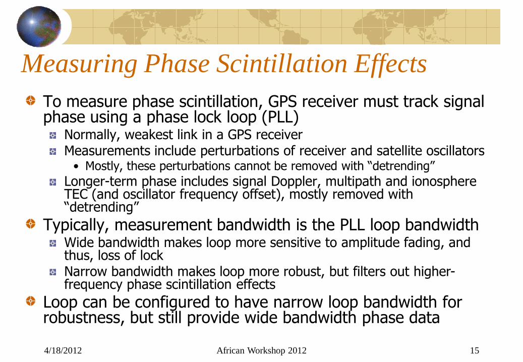
Measuring Phase Scintillation Effects
To measure phase scintillation, GPS receiver must track signal phase using a phase lock loop (PLL)
Normally, weakest link in a GPS receiver Measurements include perturbations of receiver and satellite oscillators
• Mostly, these perturbations cannot be removed with “detrending”
Longer-term phase includes signal Doppler, multipath and ionosphere TEC (and oscillator frequency offset), mostly removed with “detrending”
Typically, measurement bandwidth is the PLL loop bandwidth Wide bandwidth makes loop more sensitive to amplitude fading, and thus, loss of lock Narrow bandwidth makes loop more robust, but filters out higher-frequency phase scintillation effects
Loop can be configured to have narrow loop bandwidth for robustness, but still provide wide bandwidth phase data

4/18/2012 African Workshop 2012 16
PLL Model with Wideband Phase
Estimator
Phase Discriminator measures current PLL
50-Hz phase error – added back onto phase estimate
4/18/2012 African Workshop 2012 17
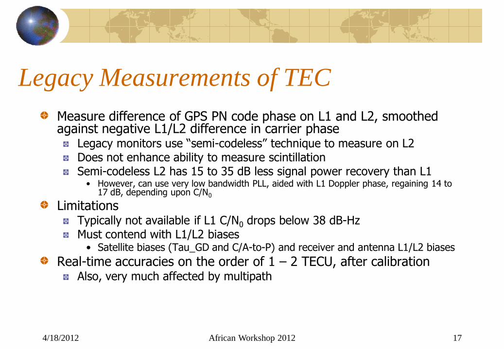
Legacy Measurements of TEC
Measure difference of GPS PN code phase on L1 and L2, smoothed against negative L1/L2 difference in carrier phase
Legacy monitors use “semi-codeless” technique to measure on L2 Does not enhance ability to measure scintillation Semi-codeless L2 has 15 to 35 dB less signal power recovery than L1
• However, can use very low bandwidth PLL, aided with L1 Doppler phase, regaining 14 to 17 dB, depending upon C/N0
Limitations Typically not available if L1 C/N0 drops below 38 dB-Hz Must contend with L1/L2 biases
• Satellite biases (Tau_GD and C/A-to-P) and receiver and antenna L1/L2 biases
Real-time accuracies on the order of 1 – 2 TECU, after calibration Also, very much affected by multipath

Evolution to Modernized GNSS
4/18/2012 African Workshop 2012 18

Legacy GSV 4004B & Antenna
4/18/2012 African Workshop 2012 19
GSV4004B GPS IONOSPHERIC SCINTILLATION AND TEC MONITOR AND OPTIONAL GPS702GG
ANTENNA
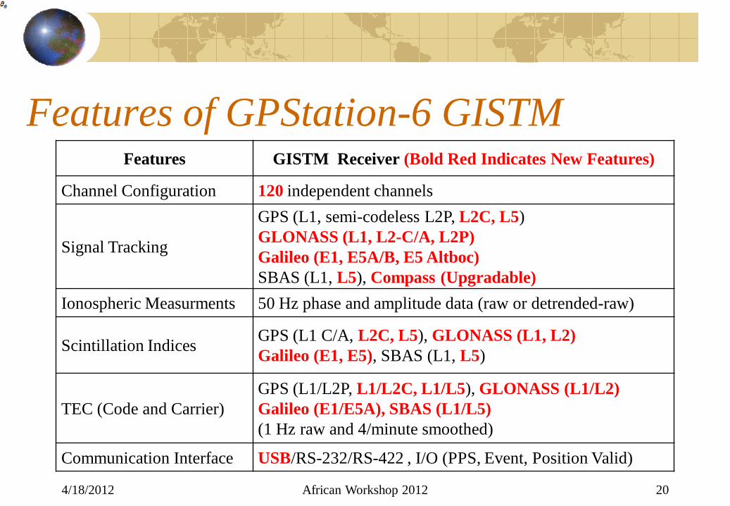
Features of GPStation-6 GISTM
4/18/2012 African Workshop 2012 20
Features GISTM Receiver (Bold Red Indicates New Features)
Channel Configuration 120 independent channels
Signal Tracking
GPS (L1, semi-codeless L2P, L2C, L5)
GLONASS (L1, L2-C/A, L2P)
Galileo (E1, E5A/B, E5 Altboc)
SBAS (L1, L5), Compass (Upgradable)
Ionospheric Measurments 50 Hz phase and amplitude data (raw or detrended-raw)
Scintillation Indices GPS (L1 C/A, L2C, L5), GLONASS (L1, L2)
Galileo (E1, E5), SBAS (L1, L5)
TEC (Code and Carrier)
GPS (L1/L2P, L1/L2C, L1/L5), GLONASS (L1/L2)
Galileo (E1/E5A), SBAS (L1/L5)
(1 Hz raw and 4/minute smoothed)
Communication Interface USB/RS-232/RS-422 , I/O (PPS, Event, Position Valid)

Improvements by Adding L2C and L5
4/18/2012 African Workshop 2012 21
5 10 15 20 25 30 35 40 45 50 55 6034
36
38
40
42
44
46
48
50
52
Elevation Angle (deg)
Me
an
C/N
o (
dB
-Hz)
L1 C/A
L2 P(Y)
L2C
L5
0 5 10 15 206
8
10
12
14
16
18
20
22
24
Observation Period (Hrs)N
um
be
r o
f S
ate
llite
s
GSV4004B (GPS Only)
GPStation-6 (GPS + GLONASS)
• Measured at Calgary, AB, Canada
• GPS Modernization improves Signal Quality – C/N0
• Adding Constellations increases Number of Ionospheric Pierce Points
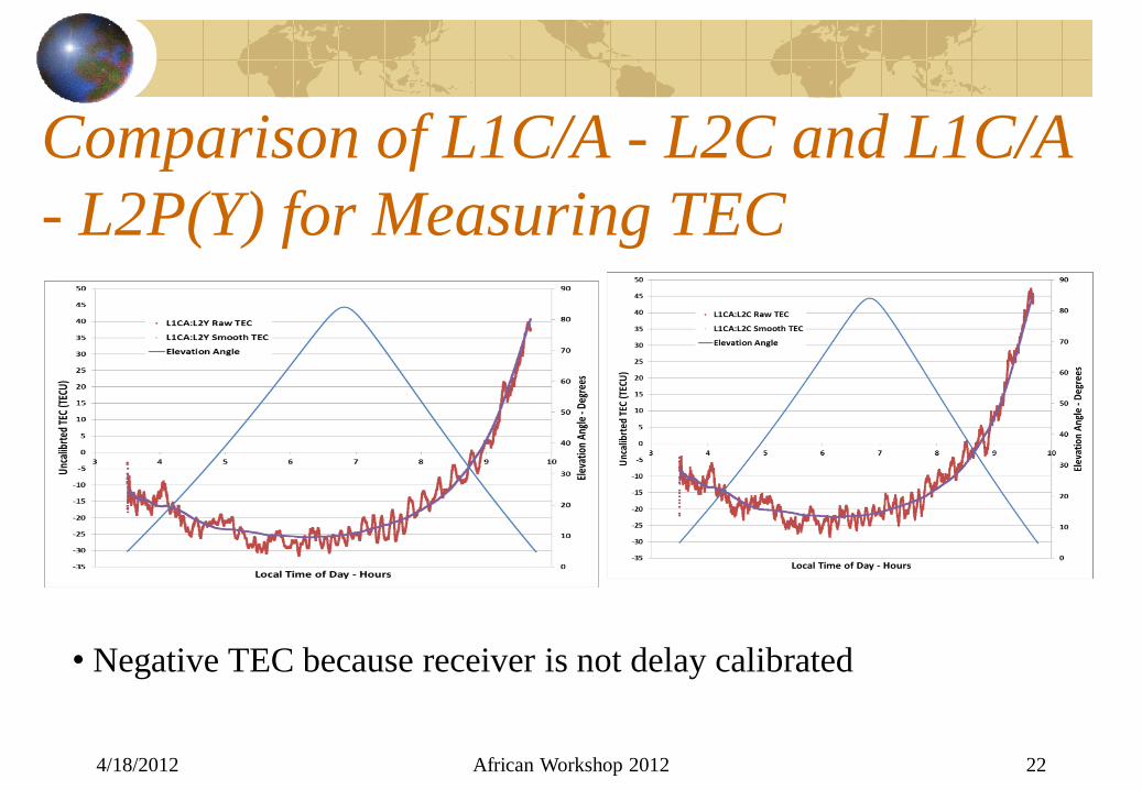
Comparison of L1C/A - L2C and L1C/A
- L2P(Y) for Measuring TEC
4/18/2012 African Workshop 2012 22
• Negative TEC because receiver is not delay calibrated
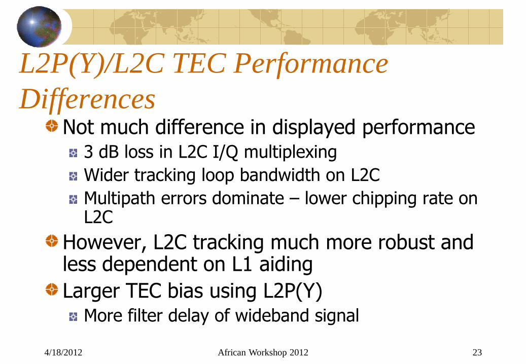
L2P(Y)/L2C TEC Performance
Differences Not much difference in displayed performance
3 dB loss in L2C I/Q multiplexing
Wider tracking loop bandwidth on L2C
Multipath errors dominate – lower chipping rate on L2C
However, L2C tracking much more robust and less dependent on L1 aiding
Larger TEC bias using L2P(Y) More filter delay of wideband signal
4/18/2012 African Workshop 2012 23

GPS Scintillation Measurement Comparisons
4/18/2012 African Workshop 2012 24
21:00 22:00 23:00 00:00 01:00 02:000
0.1
0.2
0.3
0.4
0.5
0.6
0.7
Local Time (Hrs)
Am
plitu
de
Scin
tilla
tio
n In
de
x (
S 4)
GSV4004B
GPStation-6
21:00 22:00 23:00 00:00 01:00 02:000
0.1
0.2
0.3
0.4
0.5
0.6
0.7
0.8
0.9
Local Time (Hrs)
Ph
ase
Scin
tilla
tio
n In
de
x (
)
(60
-se
co
nd
s)
(ra
d)
GSV4004B
GPStation-6
• Calama, Chile • S4 – Legacy vs
Modernized
• – Legacy vs
Modernized
• Comparison shows excellent backward compatibility

Modernized Monitor Includes GLONASS
4/18/2012 African Workshop 2012 25
21:00 22:00 22:00 23:00 00:000
0.2
0.4
0.6
0.8
1
1.2
1.4
Local Time (Hrs)
Am
plitu
de
Scin
tilla
tio
n In
de
x (
S 4)
PRN 1
PRN 2
PRN 23
21:00 22:00 22:00 23:00 00:000
0.1
0.2
0.3
0.4
0.5
0.6
0.7
0.8
0.9
1
Local Time (Hrs)
Ph
ase
Scin
tilla
tio
n In
de
x (
)
(60
-se
co
nd
s)
(ra
d)
PRN 1
PRN 2
PRN 23
• S4 •
SBAS GEO Measurements
4/18/2012 African Workshop 2012 26
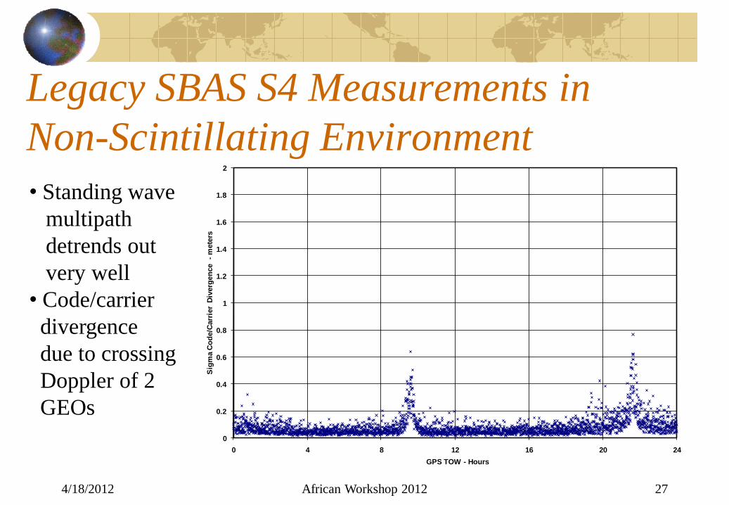
Legacy SBAS S4 Measurements in
Non-Scintillating Environment
4/18/2012 African Workshop 2012 27
0
0.2
0.4
0.6
0.8
1
1.2
1.4
1.6
1.8
2
0 4 8 12 16 20 24
Sig
ma C
od
e/C
arr
ier
Div
erg
en
ce
-m
ete
rs
GPS TOW - Hours
• Standing wave
multipath
detrends out
very well
• Code/carrier
divergence
due to crossing
Doppler of 2
GEOs

Easy to Distinguish between Multipath and
Amplitude Scintillation from GEOs
4/18/2012 African Workshop 2012 28
0
0.5
1
1.5
2
2.5
3
0 0.1 0.2 0.3 0.4 0.5 0.6 0.7 0.8 0.9 1
Sig
ma
_C
od
e_
Ca
rrie
r D
ive
rge
nc
e -
me
ters
Corrected S4
Everything above the line is likely multipath fading plus noise
Sigma_PR < 2.9412 X Corrected_S4 - .4412
• No scintillation
• Slow varying
standing wave
multipath
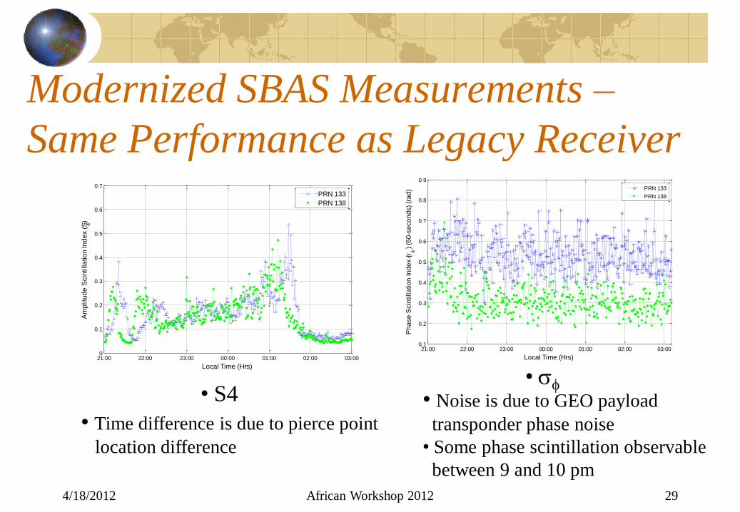
Modernized SBAS Measurements –
Same Performance as Legacy Receiver
4/18/2012 African Workshop 2012 29
21:00 22:00 23:00 00:00 01:00 02:00 03:000.1
0.2
0.3
0.4
0.5
0.6
0.7
0.8
0.9
Local Time (Hrs)
Ph
ase
Scin
tilla
tio
n In
de
x (
)
(6
0-s
eco
nd
s)
(ra
d)
PRN 133
PRN 138
21:00 22:00 23:00 00:00 01:00 02:00 03:000
0.1
0.2
0.3
0.4
0.5
0.6
0.7
Local Time (Hrs)
Am
plitu
de
Scin
tilla
tio
n In
de
x (
S 4)
PRN 133
PRN 138
• S4 •
• Time difference is due to pierce point
location difference
• Noise is due to GEO payload
transponder phase noise
• Some phase scintillation observable
between 9 and 10 pm

Scintillation Monitoring
Limitations That Apply to Both
Legacy and Modernized
Monitors
4/18/2012 African Workshop 2012 30
4/18/2012 African Workshop 2012 31
General GNSS Receiver Limitations in
Scintillation Environment Phase Scintillation
Generally, not a problem at L1 or L5, or on L2C • Unless a very narrow tracking bandwidth is used • No worse than low-grade TCXO typically found in GPS Receivers • Requires relative wide bandwidth PLL for phase tracking
Larger problem for “semi-codeless P(Y)” on L2 • Very narrow bandwidth PLL coupled with erroneous (required) aiding with
L1 phase (doesn’t agree with Doppler aiding)
Amplitude Scintillation Primary culprit for loss of phase lock
• Deep and long fades steal signal from PLL • Narrower bandwidth is better, but could require a better oscillator, and
may lose lock due to strong phase scintillation • False alarms from lock detectors during fades (apparent loss of lock)
Loss of data (symbols) from SBAS signals

Phase Scintillation Limitations
4/18/2012 African Workshop 2012 32
4/18/2012 African Workshop 2012 33
GNSS Scintillation Monitor Limitations
in Phase Scintillation Environment Can’t measure scintillation at “semi-codeless” L2 P(Y) – Loop bandwidths too narrow Measurement limitations on coded signals (L1, L2C and L5) dominated by receiver oscillator
Typical receiver oscillator phase noise masks phase scintillation (See PSDs and plots in next charts) Thermal Noise limitation is about 0.1 radian @ 30 dB-Hz OCXO phase noise typically better than 0.05 radians
Limitation can be overcome by differencing phase between satellites
Creates a requirement for high-rate data collection and substantial post processing

4/18/2012 African Workshop 2012 34
Phase Noise PSD Comparisons
-80
-70
-60
-50
-40
-30
-20
-10
0
10
0.001 0.010 0.100 1.000 10.000 100.000
Frequency Offset - Hz
Po
we
r S
pe
ctr
al D
en
sit
y -
dB
-ra
d2/H
z
TCXO Spectral DensityOCXO Spectral DensityWeak VHF Scintillation Scaled to L1Stronger Antofagosta ScintillationTCXO Differenced Spectral DensitySBAS GEO Signal

4/18/2012 African Workshop 2012 35
Antofagosto Phase Scintillation vs.
TCXO Phase Noise
= 0.396 radians = 0.46 radians

4/18/2012 African Workshop 2012 36
Tradeoffs Regarding Using Low-Noise
Oscillators (OCXOs) Cost of low-noise OCXOs has diminished somewhat over recent years
The cost driver is their packaging with the receiver (low-volume quantities)
• This packaging must also meeting international radiation and conductive emission (CE) requirements
As stated, TCXO noise can be eliminated by differencing phase across satellites
Creates a data storage and post-processing burden Receiver tracking bandwidth must be kept high, preventing tracking in noisy conditions and during deep fades

Amplitude Scintillation
Limitations
4/18/2012 African Workshop 2012 37

4/18/2012 African Workshop 2012 38
Scintillation Monitor Limitations in
Amplitude Scintillation Environment Amplitude Scintillation
High S4 can cause loss of phase lock
• S4 is still usually valid – it is based upon non-coherent power measurements, at least for short to medium length fades
• See state diagram
Multipath fading limits minimum S4 capability
• Longer duration, but shallow fades
• Can be detected and eliminated because multipath also causes code/carrier phase divergence – scintillation does not

Fade Depths and Widths Using 50
Hz Amplitude Samples
4/18/2012 African Workshop 2012 39
0 5 10 15 20 25 30 35 40 4510
20
30
40
5050Hz c/no for 8 November 2004 01-02 UT Tromso GSV4004
23.3 23.35 23.4 23.45 23.5 23.55 23.6 23.65 23.725
30
35
40
45
50
time (minutes since start of hour)
c/n
o (
dB
Hz)

Distinguishing Between Amplitude
Scintillation and Multipath Fading
4/18/2012 African Workshop 2012 40
0
0.05
0.1
0.15
0.2
0.25
0.3
0.35
0.4
0.45
0.5
0.55
0.6
0.65
0.7
0.75
0.8
0.85
0.9
0.95
1
0 0.1 0.2 0.3 0.4 0.5 0.6 0.7 0.8 0.9 1
Sig
ma
_C
od
e_
Ca
rrie
r D
ive
rge
nc
e -
me
ters
Corrected S4
Everything above the line is likely multipath fading plus noise
Sigma_PR < 0.625 X Corrected_S4 -
• No Scintillation
• Varying Multipath
• All GPS Satellites
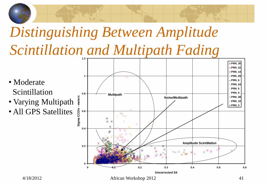
Distinguishing Between Amplitude
Scintillation and Multipath Fading
4/18/2012 African Workshop 2012 41
0
0.2
0.4
0.6
0.8
1
1.2
0 0.1 0.2 0.3 0.4 0.5 0.6
Uncorrected S4
Sig
ma C
CD
iv -
me
ters
PRN_30
PRN_22
PRN_14
PRN_29
PRN_6
PRN_24
PRN_5
PRN_9
PRN_28
PRN_10
PRN_3
Amplitude Scintillation
MultipathNoise/Multipath
• Moderate
Scintillation
• Varying Multipath
• All GPS Satellites

Multipath Fading Tracking SBAS
Signals
4/18/2012 African Workshop 2012 42
No Scintillation,
Slow Varying Multipath
2 SBAS Geostationary
Satellites
0
0.5
1
1.5
2
2.5
3
0 0.1 0.2 0.3 0.4 0.5 0.6 0.7 0.8 0.9 1
Sig
ma
_C
od
e_
Ca
rrie
r D
ive
rge
nc
e -
me
ters
Corrected S4
Everything above the line is likely multipath fading plus noise
Sigma_PR < 2.9412 X Corrected_S4 - .4412

4/18/2012 African Workshop 2012 43
Signal Tracking State Diagram
• Not necessarily implemented in all receivers, but is in Scintillation
Monitors described here

Example Phase Measurements
Collected in San Francisco Area
Non-Scintillation Environment
4/18/2012 African Workshop 2012 44

Typical Plot of 1, 3 and 10 Second
Sigma-Phi from All Satellites in View
4/18/2012 African Workshop 2012 45
0
10
20
30
40
50
60
70
80
90
100
0
0.1
0.2
0.3
0.4
0.5
0.6
0.7
0.8
0.9
1
0 4 8 12 16 20 24
C/N
0 -
dB
-Hz,
Ele
v A
ng
le -
Deg
rees
Sig
_P
hi -
Rad
ian
s
GPS TOW - Hours
Sig_Phi_1
Sig_Phi_3
Sig_Phi_10
ElevAngle
C/N0

SBAS GEO Phase Measurements
4/18/2012 African Workshop 2012 46
0
10000
20000
30000
40000
50000
60000
70000
80000
90000
100000
0
0.5
1
1.5
2
2.5
3
3.5
4
4.5
5
0 4 8 12 16 20 24
Lo
ck T
ime -
Sec
Sig
_P
hi -
Rad
ian
s
GPS TOW - Hours
Sig_Phi_1
Sig_Phi_3
Sig_Phi_10
Lock Time
• Phase Degraded by
GEO Transponder
Code/Carrier Control
• However, constant
45 degree elevation –
no multipath effects