Embed Size (px)
Citation preview

Evolution of Prestressing SystemsHR GANZ
VSL International Ltd, LyssacacWSwitzerland
1. Introdllctlon
The idea of prestressed concrete goes back more than 100 years. Modem development of prestressed concretehowever, is attributed to Eugene Freyssinet of France who started using high strength steel wires for post-tensioningconcrete beams in 1928. By 1939, he had designed the Freyssinet system with conical wedges for anchoring 0 5mmwires at the ends of prestressed members as well as special jacks for use in stressing and anchoring the wires. From the1940’s onwards he designed and built a significant number of impressive post-tensioned structures including thefamous bridge over the river Marne in Lucancy. Other engineers contributed significantly to the development of post-tensioned concrete and prestressing systems such as F. Dischinger with the introduction of external post-tensioning.Dyckerhoff & Widmann developed a 0 25mm stressbar system (Dywidag system). Leonbardt & Bauer in Germanyand Magnel in Belgium introduced their wire prestressing systems. In the second half of the 1940’s the Swiss engineersBirkenmaier, Brand&C, Ros and Vogt created the BBRV prestressing system for 0 7mm wires anchored in a steelanchor head by cold formed button heads. This early period after World War II brought a rapid development, and in1953 some 25 different post-tensioning systems were known, two third of them in Germany, the remaining in Europeexcept for two systems in the USA, see MUHer”. Only relatively few of those early systems survived the introductorystage, and actually are available still today.
The early 1950’s saw the creation of the International Federation of Prestressing (FIP) who subsequently contributedsignificantly to the development of prestressed concrete through the preparation of recommendations and guides forprestressing materials and systems, and design and construction of prestressed structures.
The 1960’s brought the introduction of 7-wire strand prestressing systems for monostrand tendons, particularly in theUSA, and for multistrand tendons, e.g. VSL post-tensioning system.
Post-tensioned tendon forces were limited initially to about 400 kN but increased rapidly in the late 1950’s and 1960’sinto the several thousands kN range. Today, the maximum tendon capacity typically found in post-tensioning systemapprovals is in the 10,OOO - 15,000 kN range.
Today’s market size for post-tensioning steel is estimated to 600,000 - 800,OOO tonnes/year. The USA alone contributeabout 100,000 tonnes. Between 50-75% of this steel goes into bridge construction however, a significant part in theorder of 25% is used in buildings. Other typical applications for post-tensioning tendons include engineering structuressuch as reservoirs, silos, offshore structures, containment structures, etc., and slab on ground. For reference only, thepretensioning steel consumption is estimated at 3-5 times the size of the post-tensioning market.
Most of the prestressed structures built in these first 50 years in accordance with the rules for good design, detailing,and practice of execution have demonstrated an excellent durability of prestressed concrete, in general, and ofprestressing tendons in particular. The FIP Recommendations2’ for corrosion protection of prestressing steels state that“It must be emphasised that instances of serious corrosion in prestressed concrete structures are rare when oneconsiders the volume of prestressing steels that have been consumed world wide over the years”.
The prestressing / post-tensioning systems have continuously evolved since their introduction about 50 years ago. Thispaper gives a summary of today’s status and recent evolutions considered important for the performance and durabilityof these systems. The emphasis will be on improved materials, products, specifications, and procedures for post-tensioning tendons. While similar in many aspects, ground anchors, stay cables, and pretensioning are not consideredin this paper.
fib Bulle~rn~~IS: Durabilily ofposl-tensioning terdons 155

2. Post-tensioning system components
2.1 Prestressing steels for post-tensioning systems
Today three main forms of prestressing steels are used for post-tensioning:
. Cold drawn plain wire of 5-7 mm nominal diameter, and specified tensile strength of 1670- 1860 MPa.
. Cold drawn plain prestressing strand of 13-16 mm nornina diameter, and specified tensile strength of 1770 - 1860MPa.
l Hot rolled plain or ribbed prestressing bars of 15-40 mm nominal diameter, and specified tensile strength of 1030 -1230 MPa.
The most important steel for use in post-tensioning is the ‘I-wire prestressing strand. The three types of prestressingsteel are available as uncoated, bare steel or with metallic and non-metallic coatings applied in the factory. The 7-wirestrand is also available with plastic sheathing.
2.1.1 Uncoated, bare prestressing steel
These steels have been standard&d since long, and reference is often made to ASTM British, Euronorm, or Japanesestandards, see Table 1. These standards assure high quality prestressing steels. The following is a brief summary of themain relevant characteristics of the prestressing steels for post-tensioning, and recent evolutions.
Type of steel ASTM Erltlsh Euronorm JapaneseStandards Standards Standards Standards
. Cold drawn wire A 421 BSS696 Draft EN 10136-2 JIS G 3536
. 7-wire strand A 4 1 6 BS 5696 Draft EN 10136-3 JIS G 3536
. Hot rolled bar A 7 2 2 BS 4466 Draft EN 101364 JIS G 3109
I I 1 I
Table 1: Freguent& mfemnced standerds for pmstmssing steel
(1)
(2)
(3)
(4)
(5)
Geometry of prestressing steel: This is usually defined with a nominal diameter, and nominal cross sectional areaImportant for use in post-tensioning systems are the tolerances in cross sectional dimensions. Unfortunately, somestandards such as ASTM A416 still permit quite large tolerances which may cause problems with the behaviour ofanchorages during stressing operations, e.g. excessive friction or scrapping of steel. Recent standards such asEuropean EN 10138 permit a tolerance of _+ 2 % on the mass of the steel which avoids such problems.
Specified strength of prestressing steel: This is usually defined with a characteristic breaking load, and acharacteristic proof load (0.1 - 0.2 % permanent elongation). Drafts of EN 10138 now also include an upper limitof the maximum breaking load to avoid excessive cold working of the steel and consequential loss of ductility.This limit is about 15% above the characteristic breaking load.
Ductility of prestressing steel: This is usually defined with a minimum elongation of 3.5% of the steel atmaximum load over a given specimen length. In addition to the minimum elongation, the steel shall break in aductile manner with corresponding reduction of area, visible to the unaided eye. For wire, the reverse bend testhas proven to be practical and reliable. A minimum number of bends is specified around a given bend radius. Acorresponding test has been developed for 7-wire strand by FIP and PTI, these are the deflected tensile test andone-pin test, respectively. This test has recently found its way into standards. This test limits the reduction ofstrength of a strand deviated around a specified mandrel to 28O/o for post-tensioning applications.
Relaxation of prestressing steel: This is usually defined as a percentage loss of force of a prestressing steel held atconstant elongation over 1000 hours, initially stressed to 70% or 80% of its specified strength. While in the pastseveral relaxation classes did exist, the trend is clearly to one class for very low relaxation only for all products,e.g. 2,5% for 7-wire strand in 1000 hours when initially stressed to 70% of the characteristic strength.
Fatigue strength of prestressing steel: This is usually defined as a stress range which can be sustained by the steelwithout failure over 2~10~ cycles at an upper load corresponding to 70% of the characteristic breaking load.Specified fatigue stress ranges are in the order of 180-200 MPa.
156
(6) Stress corrosion test for prestressing steel: This test shall confirm that a particular type of prestressing steel issufftciently resistant to stress corrosion. Different test methods have been proposed and used. The test methodmost commonly referred to is the one developed by FIP in which the prestressing steel is immersed under tensioninto an ammonium thiocyanate solution. A minimum time of exposure before failure is specified for each type ofprestressing steel. Since the test results may show significant scatter, a minimum and average value is specified.These values are in the order of 1.5 - 5 hours for wire and strand, but are significantly larger for bars with largediameter.
The FIP test has been developed and is well adapted for cold drawn wire and strand. However, there is somedoubt of its suitability for other types of steel such as quenched and tempered prestressing wire. Other proceduressuch as the DIBT-test in Germany, and the test in distilled water in France are also used.
Cold drawn wire, 7-wire strand, and hot rolled bar which comply with standards including the above characteristics (1)to (6) can generally be expected to demonstrate properties suitable for post-tensioning, and good durability. Othertypes of prestressing steel not covered by the above should be considered with caution before using for post-tensioning.This comment applies e.g. for quenched and tempered wire which is widely used in pretensioning in Japan, but whichis not recommended for use in post-tensioning, see FIP Notes3’.
2.1.2 Coated prestressing steel
Mainly three types of coatings have been used. These are zinc, zinc and aluminium, and epoxy. Detailed informationon these methods of protection of prestressing steel can be found in a fib report4’.
2.1.2. I Zinc coating
Zinc coated prestressing steel is relatively rarely used for post-tensioning. Its main use is in stay cables. However, ithas occasionally been used, e.g. for temporary applications over extended periods of time.
Zinc provides a sacrificial protection of the prestressing steel. Corrosion protection by zinc depends primarily on theconsumption rate and the available thickness of the zinc layer.
Galvanised prestressing steels have been standardised in the French standard NF A 35035. It is understood that aEuropean standard and a IS0 standard are being prepared on galvanised prestressing steel for prestressing. Thesestandards have been specifically written for post-tensioning applications and include e.g. tolerances on the thickness ofthe zinc layer. Final drawing of the coated wires permits to achieve relatively tight tolerances on the coating thickness.This is important for the performance of wedge anchorages in particular. There are other standards for zinc coated steelbut these have not been written for prestressing steel specifically, and should be used with caution.
Prestressing steels may be galvanised by a number of processes. The safest process to avoid the risk of hydrogenembrittlement is hot dip galvanisation, see FIP Notes”. According o tt he same reference, cold drawn wire and strand isthe least sensitive steel to hydrogen embrittlement.
2.1.2.2 Zinc and aluminium coating
The same comment as for zinc coating applies to the use of this product in post-tensioning. Coatings of zinc containingapproximately 5% aluminium appeared in the 1980’s. This type of coating provides an improved protection to theprestressing steel compared to pure zinc, as determined in accelerated salt spray tests. In addition, it has a higherhardness than pure zinc which is seen as an advantage for anchorage by wedge.
2.1.2.3 Epoxy coating
Epoxy coated prestressing steel has been mainly applied for pretensioning applications. However, some applicationsfor temporary use, and for permanent use as ungrouted external post-tensioning have been reported, e.g. in Japan.
Experience has shown that epoxy coated strand needs to have the interstices between wires completely filled for longterm corrosion protection. The thickness of coating needs to be carefully controlled for reliable anchorage by wedges.There is some discussion whether the coating thickness needed for protection. and the corresponding tolerances, makethis product suitable for post-tensioning anchored by wedge. ASTM has issued a standard A822 for epoxy coatedstrand.
2.1.3 Sheathed prestressing steel
Prestressing strand protected with a layer of grease and an extruded HDPE sheathing has been used for several decadesprimarily as monostrand for post-tensioning of building slabs. Specifications for this type of tendon have beenintroduced by the Post-Tensioning Institute (PTI) in the USA. These specifications have been amended recentiybetween PTI and AC16), and are considered to provide a reliable level of long term protection. Key aspects for thedurability of these tendons are the material specifications for grease and HDPE. France and Belgium are working on adraft standard for monostrands which is being used also by a European working group for the guideline for Europeanapproval of post-tensioning systems”. The novelty of these two drafts is that performance characteristics are specifiedfor the raw materials grease and HDPE before and after manufacturing of the sheathing. This permits a control of thequality of the manufacturing process.For applications where the sheathed monostrand is not encased in concrete or grout, and allowed to move freely insidea duct, the grease is often replaced by wax, and the HDPE sheathing applied tightly around the strand. HOWLMX, thistype of monostrand is suitable only for ungrouted applications since it would produce excessive friction in groutedconditions. For such ungrouted applications e.g. in stay cables, the wax and HDPE sheathing has also been combinedwith zinc coating.
2.2 Anchorage systems for post-k%msioning systems
Anchorages are the heart of any post-tensioning system, and are usually based on proprietary designs by the systemowner. It is important to recognise that the basic concepts of anchoring prestressing steels mostly are quite simple,however, that the actual behaviour is significantly more complex, and often is beyond mathematical or even numericalanalysis. Hence, much of the design and confirmation of the anchorage concepts still relies on experience and detailedtesting.
Post-tensioning anchorages can be grouped into active or stressing anchorages, i.e. allowing stressing of the tendon,passive or dead endanchorages, i. e. not permitting stressing, and coupling anchorages, to connect adjacent segmentsof tendons. In this paper, the presentation of post-tensioning anchorages will be based on the concept of anchoring theprestressing steel, and the method of transfer of the tendon force onto or into the structure.
2.2.1 Anchorage of the prestressing steel
2.2.1. I Anchorage by wedge eflect
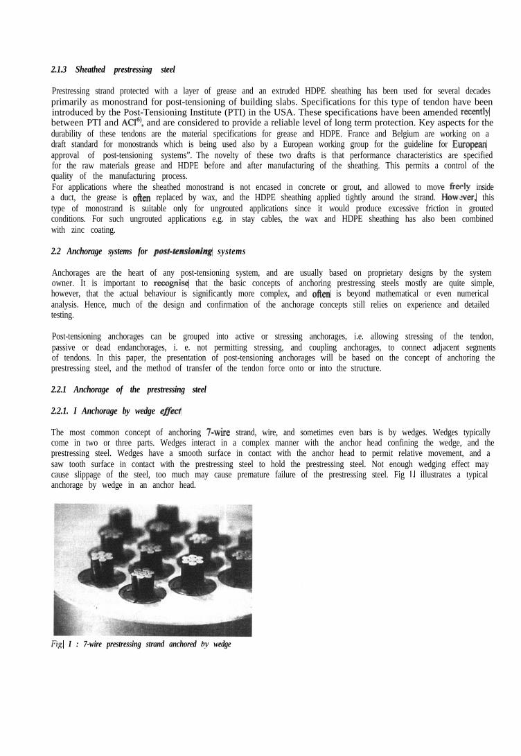
The most common concept of anchoring 7-wire strand, wire, and sometimes even bars is by wedges. Wedges typicallycome in two or three parts. Wedges interact in a complex manner with the anchor head confining the wedge, and theprestressing steel. Wedges have a smooth surface in contact with the anchor head to permit relative movement, and asaw tooth surface in contact with the prestressing steel to hold the prestressing steel. Not enough wedging effect maycause slippage of the steel, too much may cause premature failure of the prestressing steel. Fig I. illustrates a typicalanchorage by wedge in an anchor head.
FIR. I : 7-wire prestressing strand anchored bv wedge

2.2.1.2 Anchorage by bearing
This is the concept used for button headed wire anchored inside an anchor head and far nuts sitting on a bearing plate.Since the contact surface between anchor head and button head is comparable to the section of the wire, the contactstresses have the same order of magnitude as the strength of the prestressing steel. While these stresses are beyond anylimits given in standards for the lower strength anchor head material, the anchorage concept performs perfectlysatisfactory anyway. Fig. 2 shows a typical anchorage for button headed wire.
Fig. 2: Prestressing wire anchored by button head
2.2.1.3 Anchorage by nut and thread
This is the common anchorage concept for prestressing bar. The transfer of load across the thread is statically highlyindeterminate, and actually only a fraction of the threads is effective in transferring the load at one time. Fig. 3 showstypical nut and thread anchorages on ribbed bar.
Fig. 3: Prestressing bar anchored by nut and thread
2.2.1.4 Anchorage by compressionj&ing
This is a special anchorage concept mainly used for 7-wire strand. It consists of a metallic cylinder with a hardenedinsert liner into which the strand is installed. lhe strand and cylinder with liner are then pulled through a die whichplastically deforms the cylinder to provide a tight fit onto the strand and liner.
2.2.1.5 Anchdrage by bond
Another method of anchoring prestressing steel in a dead end is by direct bond to the surrounding concrete similarly topretensioning. Often bond of the prestressing steel is improved by deformations on the steel, or by forming a bulb fromthe 7 wires at the end of the strand
The behaviour and performance of all the above anchorage concepts depend significantly on the manufadurmgtolerances, and the consistent quality of these tolerances. They also depend on the preparation of the contact surf&s,e.g. lubrication, oxidation/corrosion, and cleanliness. It is therefore, indispensable to have specialists for installation

and assembly of the anchorages on site who are knowledgeable of these aspects and in the behaviour of the anchorages,and who can take appropriate measures, if needed.
2.2.2 Transfer of load to the structure
2.2.2. I Basic bearing plate
This is a simple steel plate which transfers the tendon load applied by the anchor head by direct bearing into theconcrete or onto other materials such as steel, masonry, and timber. This concept has been used since the start of post-tensioning, and is used for tendons of all types of prestressing steel. Fig. 4 illustrates such an anchorge with basicbearing plate.
Fig. 4: &sic bearing plate fo* m&strand tendon
2.2.2.2 S’c&l bearing plate
These are either machined or typically cast iron anchorage bodies which transfer the load f&n the anchor head to thesurrounding concrete at several levels via flanges, etc. More recently high strength concrete has also been used. Forsmall tendon sizes there are also special bearing plates into which the anchor head is integrated i.e. one component forboth functions only. Fig. 5 presents such special bearing plates for multistrand and monostrand tendons.
Fig. 5: Special bearing plates:
a) Multistrand tendon b) Monostmnd tendon
The contact stresses between bearing plate and concrete can reach several times the concrete strength, already at thetime of transfer. This is only possibly by adequate confinement of the concrete in the immediate vicinity of the bearingplate. This area which needs confinement is often called local zone of the anchorage. Confinement is typically providedby spiral reinforcement or stirrups. This confinement reinforcement is often considered part of the system. Thebehaviour of the local zone and the concrete beneath it is complex. Therefore, verification of the load transfer isgenerally based on testing. However, for basic bearing plates, PT18’ permits design of the anchorage zones using basicbearing plates by empirical design procedures. This is however, not permitted elsewhere.

2.2.3 Coupling of tendons
Coupling of tendons is common in certain parts of the world but typically avoided in others such as the USA andFrance. A common type of coupling tendons is by having two anchor heads, one for each tendon segment, back toback, and connected by a threaded sleeve. Another common type is by overlapping the tendon ends in a commoncoupling anchorage, usually one tendon segment anchored in the centre, the other along the perimeter. Fig. 6 illustratessuch coupling anchorages.
Fig. 6: Tendon couplers:
‘
a) By threaded sleeve b) By overlapping of tendon
Couplers form a discontinuity in the tendon for the flow of the tendon force and particularly for grouting. Specialprocedures and care are needed to assure reliable filling of couplings with grout. Couplers also introducediscontinuities in the tlow of forces in the structure, and require careM detailing and supplementary reinforcement atthe joints. This discontinuity has caused problems in structures in the past. It is therefore, common practice to notcouple more than 500/o of the tendons at one particular section, and add sufficient non-prestressed reinforcement.
2.2.4 Performance of post-tensioning anchorages
While many post-tensioning anchorages still look similar to those at the early stages of prestressed concrete, they havegone through a continuous evolution. Their quality has steadily improved, and has reached an exceptionally high levelof performance and reliability. Acceptance of the post-tensioning anchorages is today widely based on detailed testingwith stringent acceptance criteria. Such test procedures have been developed in particular by FIP9’ and have beenimplemented in many countries in Europe. They will form the basis of the Mure European approval of post-tensioningsystems .‘) They have also been widely accepted throughout Asia including Japan. Also the acceptance tests in the USAby PTI” are converging gradually towards the FIP procedures.
These system acceptance tests include three basic test procedures: The static tensile test which primarily confirms thereliable anchorage of the prestressing steel; the load transfer test which verifies the transfer of the tendon load from theanchorage into the surrounding concrete; and the fatigue test which assesses the performance of the anchorage understress variations in the tendon. Acceptance criteria as per FIP are stringent since the anchorage is required e.g. toachieve an ultimate load of 95% of the actual tensile strength of the prestressing steel with a minimum of 2%elongation. This corresponds approximately to the specified ultimate tendon capacity. In the USA typically 95% of thespecified tendon strength is required, see e.g. PT18’. There is still disagreement whether fatigue tests shall be requiredfor all types of tendons, unbonded tendons only, or bonded tendons only. It is the opinion of the experts who preparedthe FIP recommendations9) that the fatigue requirements should apply to all systems since it is considered confirmationof the good detailing and robustness of the anchorage even though some types of tendons may not be subjected tosignificant fatigue loading.
Apart l?om the above discussed performance, post-tensioning anchorages absolutely need to have a reliable quality topermit safe stressing of the tendons on site, every time. This is achieved by design of the components with sufficientsafety margin, consistent quality of manufacturing, and installation by experienced and well trained personnel.However, it also requires selection of suitable materials for each of the anchorage components. The selected materialsneed, apart from strength, to offer in particular sufficient ductility. They also need to be tough and insensitive to minordefects which are hard to detect visually. A suitable choice of material oflen provides larger safety margins than thosetypically provided by design.

It may be worthwhile mentioning that in addition to the above performance testing each post-tensioning anchorage isfinally test loaded on site during stressing of the tendon, sometimes to values within 15-20% from the specified tendoncapacity. Often, this is the highest load the anchorage ever sees during the life of the structure because long term losseswill reduce the tendon force by IO-20%, and force increase due to overload is rarely occurring in post-tensioningtendons.
2.3 Ducts
Ducts serve different objectives in post-tensioning. For internal tendons, they first create the void in a concretestructure, in a defined aligmnent, which allows installation and the free movement of the prestressing steel duringstressing. They also form the contact surface which determines the t+iction losses during stressing. Finally, they formthe interface between prestressing steel and structure to transfer bond forces. For external tendons, the ducts serve as aguide for installation of the prestressing steel. They again form the contact surthce which determines the friction lossesduring stressing. Last but not least the duct needs to provide a robust encapsulation of the tendon for long tetmprotection to compensate for the lack of concrete cover. Obviously, duct materials shall not be harmful to theprestressing steel.
While not structural, ducts ar’: an essential component of any post-tensioning system for reliable installation, stressing,and grouting, and for long tet n durability of the tendon. This has not always been recognised. In particular in the earlyyears, no ducts at all or improvised solutions with cardboard were used. Ducts made of materials which are potentiallyharmful to the prestressing steel such as PVC have also been used.
The following is a brief review of different types of ducts considered suitable for post-tensioning.
2.3. I Corrugated metal ducts
This is the most widely used type of duct for internal bonded post-tensioning. It is made from steel strips, spirallywound into a continuous duct. The thickness of the sheet metal strips is usually between 0.2 and 0.7 mm depending onthe duct size, whether tendons are prefabricated or installed on site after concreting, and depending on the expectedconcrete pressure or other loads during construction. Individual segments of duct are typically joined with a sleevemade of an oversized duct which can be threaded onto the corrugation, and sealed with tape or equivalent products.Fig. 7 shows such a typical corrugated duct with sleeve and grout vent.
Fig. 7: Comrgatad metal ship duct with duct sleeve and grout vent
In. Europe, this type of duct has been standardised in EN 523 and 524. This standard can be considered to assure use ofstate-of-the art corrugated duct Performance specifications cover the essential requirements, and detailed testprocedures permit the verification of the actual behaviour. The main characteristics specified in the standard includeduct geometry; stiflhess of the duct to avoid excessive deflection of ducts between supports during concreting;flexibility of the duct to allow defined smooth curvatures; resistance to transverse loads to avoid collapse of the ductduring concreting; resistance to longitudinal loads during construction; and leak tightness of the duct to water. Similarcharacteristics are specified e.g. by the PTl@ in the USA.

Corrugated ducts must be free of rust to assure reliable friction losses during the stressing of the tendon. The use ofgalvanised duct is common in many parts of the world to avoid the corrosion of the duct surface. The galvanising alsoserves as a lubrication and thus, reduces the friction losses compared with a dry and clean black steel surface.However, there are countries who do not permit the use of galvanised duct because of the fear that galvanising couldcause hydrogen embrittlcment of the prestressing steel. Even though widely used there is no evidence known to theauthor where the use of galvanised duct would have caused damage to tendons made of cold drawn wire and 7-wirestrand.
2.3.2 Corrugated plastic ducts
Corrugated plastic ducts of the type typically used as drainage pipes have been installed already more than 30 years agofor bonded internal tendons. However, some of this type of duct has not performed as expected and has led to excessivewobble of the tendons, excessive friction losses during stressing, and leakage of grout during injection. These problemswere mainly due to the flexibility of this type of duct, and the small wall thickness.
At the begin of the 1990’s a new generation of thick-walled corrugated plastic duct for bonded, internal tendons hasbeen developed and introduced in the market. This type of duct was specifically designed for use in bonded tendons. Itwas verified for equivalent characteristics as the corrugated metal duct. In addition, the duct wall was designed such asto positively avoid cutting through by the prestressing strand. The duct system included specific couplers to connectadjacent duct segments, or to connect onto anchorages. Fig. 8 shows this type of plastic duct, with coupler and vent.
Fig. 8: Corrugated plastic duct with duct coupler and integrated Fig. 9: Coupler for plastic ducts to seal joints in precastgrout vent segmental construction.
This duct system has been confirmed by testing to provide a complete leak tight encapsulation of the prestressing steeleven across relatively wide cracks, see Abel lo) This duct system can also be detailed to provide an electrical isolation.of the prestressing tendon from the surrounding structure. This permits electrical resistance measurements to confirmthe intactness of the encapsulation at any time during the life of the structure, see Swiss guidelines”). In addition,electrical isolation protects the tendon from the effects of stray currents. The plastic duct system has also beencontirmed to reduce the risk of fretting fatigue of the prestressing steel, see Escola “I.
Several similar duct systems were gradually introduced in the market. However, no commonly accepted performancespecification was available. fib Commission 9 has recently prepared a technical report’“’ on these new types of plasticducts. It includes material specifications, acceptance criteria and test methods for component testing, and acceptancecriteria and test methods for system testing. The report recommends to subject these ducts to an approval procedureuntil sufficient experience has been collected which then may permit to standardise these duct systems. This approachhas been integrated into the draft guideline for European approval of post-tensioning systems” which requiresapproval of these ducts based on the procedures specified in the fib Report’“.
Most countries consider epoxy resin to provide sufficient protection to post-tensioning tendons crossing joints betweenprecast segments. However, the UK has specified full encapsulation for the tendons by plastic in these joints, see TR47”‘. A special plastic duct coupler has now been brought on the market which permits continuity of the encapsulationacross segment joints, see Fig. 9.
All these duct systems are seen as a complementary protection of the prestressing tendon in addition to the primaryprotection by a thick and dense concrete cover over the tendon, and the cementitious grout in contact with the
prestressing steel. The idea of this second barrier against corrosion has since many years been successfully applied toground anchors.
2.3.3 PE pipe
Thick walled PE pipe is the commonly used type of duct for external post-tensioning. The pipe serves partly similarpurposes as the internal ducts. However, since external tendons are not protected by a thick layer of concrete. there aresome differences which warrant attention. PE pipe for external tendons may be subjected to significant internalpressure during grouting, and must be designed to safely carry this pressure. The draft European approval for post-tensioning systems” e.g. specifies 1 MPa (10 bar) design pressure for the pipe. PE pipe for external tendons may besubjected to significant temperature variations. In particular, low temperatures may introduce significant restraintstresses into grouted PE pipes. Pipes with local defects or made from recycled material have cracked under suchexposure. Unlike for internal tendons, the PE pipe is the only element providing encapsulation to an external tendon.Hence, it must be completely leak tight to assure proper grouting and to assure long term protection and durability ofthe tendon. Even relatively small defects or holes in the pipe have been found to permit tendon corrosion in aggressiveenvironment.
CarehI selection of the PE material is a key element for successful use and durability of the pipes. Only new PEmaterial (granulate) should be used. Material recycled from previously used PE components shall not be used. PE pipesin accordance with the guidelines for European approval for post-tensioning systems” and ASTM D3035 or ASTMF7 14 can generally be considered suitable for use in external tendons.
Recently, the Japan Highways Administration has started the use of transparent pipe for external tendons to facilitatecontrol of the quality of grouting.
2.3.4 Steel pipe
For certain special applications, smooth steel pipe is used as duct for tendons. Such applications include e.g. longvertical tendons which are intended to be grouted completely at one time. The use of steel pipe permits to confine thegrouting pressure and thus, protect the surrounding concrete. Smooth steel pipe is also used in locations of tight tendoncurvature such as loop anchorages, and external tendon deviations. The smooth pipe can be bent in the workshop to thespecified geometry. It is sufficiently rigid to maintain the specified geometry even under relatively rough conditions.The smooth surface also reduces the secondary transverse stresses applied to the prestressing steel in tight tendoncurvatures.
The wall thickness of such pipe is often specified as 2% of the pipe diameter but should not be less than 3 mm topermit welding, if needed.
As for any duct, sealing to provide a leak tight system is also important for steel pipe. Since the steel pipe is rigidcompared to other types of duct, it can only adapt to placing tolerances at the pipe segment joints by creating a gapbetween adjacent pipe ends. Therefore, careful detailing, execution and control of the quality of pipe joints is essentialto avoid problems with leaking joints, and pipe blockages.
2.3.5 Duct diameter
The duct diameter must be sufficiently large for proper installation of the prestressing steel and for grouting of thetendon. The required duct size depends on the type of prestressing steel (diameter of steel, sheathing, etc.), the choseninstallation method (prefabricated tendon, or pushing of individual strands in-situ, etc.). and the tendon length andgeometry. As a general guidance, the cross sectional area defined by the nominal diameter of the prestressing steel,including eventual coating or sheathing, should not exceed 40% of the cross section defined by the inside diameter ofthe duct. This percentage however, is larger for bar tendons.
Too small duct sizes are considered bad practice since this may cause problems during installation. Perhaps moreimportantly, too small duct sizes may cause problems during grouting, and leave parts of the tendon incompletely filledand thus, incompletely protected for long term durability. This has been considered the cause of grouting defects foundin a recent investigation in Austria, see Eichinger et al14).

2.4 Accessories
Accessories of post-tensioning systems include such non-structural components as temporary or petmanent anchoragecaps, grout inlets and outlets (called vents in this paper), coupling connections between duct segments or between ductand anchorage, etc.
Most of these components serve temporary purpose during installation, and in particular during grouting, and haveoften not received the attention they actually deserve. Complete grouting of tendons, and consequently good durabihty,is only possible in a leak tight duct system including all connections and anchorages.
Grout vents traditionally consist of a plastic hose, closed with tie wire, and cut flush with the concrete surface aftersetting of the grout. Carefully detailed systems however, are available with threaded connections including valves andcaps. Such systems provide positive connections which resist site conditions, and which allow proper sealing of thevent after grout setting. Fig. 10 illustrates different types of vents.
Fig. IO: DSfSerent types of grout vents:
a) Smooth hose closed with tie wire b) Corrugated hose with cap c) Corrugated hose with valve
Commonly used accessories and connections for corrugated steel duct are shown in Fig. 7. These details often employthe use of tie wire and duct tape. For the recently introduced plastic duct systems which offer complete encapsulation,special coupling and connection devices have been developed which are fully compatible with the duct. Such details asshown in Fig. 8 leave no room for improvisation on site and assure consistent quality of all connections.
It is still common practice in many countries to seal anchorages for grouting either with quick-setting mortar (drypacking) or by concreting the anchorage recess before grouting. These procedures do not permit a control of the qualityof grouting at the anchorage. Most modern post-tensioning systems now include solutions with temporary and/orpermanent caps to seal the anchorage, see Fig. 11. Such solutions are recommended and positively contribute to thedurability of tendons.
Fig . I I : Caps for sealing of anchorages:
a) Tempom y cap for gmuting b) Permanent cap

Monostrand tendons with extruded sheathing provide excellent corrosion protection along the tendon length. However,the sheathing needs to be stripped at the tendon end for the anchorage of the prestressing steel. It is still commonpractice in some countries to leave a short monostrand length near the anchorage unprotected, without sheathing.Others consider this as taking unnecessary risks even for benign environment, and always require completeencapsulation. The author is of the opinion that the cost for a protective sleeve and cap to fully encapsulate themonostrand is well spent money, and that full encapsulation should be required in all cases. Fig. 12 shows the twosolutions.
Fig. 12: Monostrand tendons:
a) Fully encapsulated stmnd b) Tendon with exposed strand at anchorage
Tendon couplers are located by definition at a construction joint. Such joints by experience are known to permit easieringress of water &d eventually aggressive substances such as chlorides into the structure, and to the tendon. Tendoncouplers can be quite large, and may be subject to some relative movement during stressing of the second tendonsegment. Hence, protection and encapsulation of couplers, in particular in aggressive environment, is important but notnecessarily easy. Some engineers are of the opinion that the use of couplers should be avoided for improved durabilityof tendons.
It seems worthwhile mentioning again that the intactness of the encapsulation along the tendon, at anchorages andcouplers, can be verified by electrical resistance measurements if plastic ducts and accessories are used, see Swissguidelines”).
2.5 FRP tendons
FRP materials have been successfGlly used for a number of applications in construction. A considerable amount ofresearch and testing has been carried out on the use of FRP for prestressing tendons. Different groups work on thedevelopment of guidelines for the design of structures with FRP tendons, e.g. fib Task Group 9.3, AC1 Committee 440,and Japanese Engineers Association. A small number of projects has been carried out with FRP post-tensioningtendons, and experience is being collected on their performance in practice.
It is the opinion of the author that there is insufficient experience available to consider FRP tendons generally suitablefor post-tensioning in today’s practice. Therefore, FRP tendons are not tirther covered in this paper.
3 . Post-tensioning equipment
Reliable installation of post-tensioning systems on site requires the use of suitable special&d equipment, adapted tothe particular post-tensioning system, and operated by experienced and well trained personnel. There are three maintypes of equipment used in post-tensioning work, i.e. for installation of the prestressing steel, for stressing of thetendon, and for grouting of the duct.
Equipment for installation of the prestressing steel must ensure firm gripping of the steel without damaging it. Thisaspect is in particular important for coated and sheathed prestressing steel.
Stressing equipment for post-tensioning tendons consists of stressing jacks and accessories to temporarily hold andthen release the prestressing steel during stressing. Stressing equipment must ensure reliable stressing of the

prestressing steel to the specified load, and reliable transfer of the load 6om the jack to the permanent tendonanchorage. Stressing jack and accessories must be tilly compatible with the specific post-tensioning anchorage toensure such things as complete release of the wedges during stressing to avoid excess friction in the anchorage orscratching of the prestressing steel, and reliable seating of the wedges at transfer of the tendon load to the anchorage toassure the expected anchorage perfbrmance. Stressing equipment must also permit multiple stressing stages toaccomodate the elongation of long tendons. In addition, it must allow detensioning of a tendon, if a problem occursduring stressing. Stressing jack and accessories such as the gripping devices must permit simultaneous stressing of theentire tendon, and assure equal forces and elongations in all tendon elements even for multiple stage stressing.Stressing equipment shall be regularly calibrated by a qualified body. Many specifications require that the calibrationof the stressing equipment is not older than 6 months. Above all, stressing equipment must allow safe operation on site,every time a tendon is stressed. An unintended sudden release of the energy stored in a prestressing tendon stressed to70-80% of its strength could be disastrous.
Suitable grouting equipment is important to ensure complete filling of the duct with a properly mixed andhomogeneous grout. The equipment must permit the filling of a tendon duct in an iainterrupted operation, at theexpected speed, and up to the expected maximum pressure. Again, safety aspects are important since cementitiousgrouts are potentially harm!U to the human skin and in particular to the eyes.
For all the above reasons, post-tensioning systems typically are provided with specific proprietary equipment. It isimportant that the equipment is included in the independent assessment by a qualified body during the post-tensioningsystem approval. For its potential effect on the performance of the tendon anchorage, the FIP recommendation9’ and thedraft guideline for the European approval of post-tensioning systems” require that the tendon in the static tensile testdiscussed in Section 2.2.4 be loaded to 80% of the specified tendon strength with the stressing equipment. Only at this80% level, the load is transferred to the testing rig for further loading up to ultimate.
4. Corrosion protection of post-tensioning tendons
Corrosion protection is probably the most important aspect to achieve durable post-tensioning tendons. The objectivemust be to achieve a design life of the tendon comparable to that of the structure in which it is placed. The design of thecorrosion protection systems should take into account that most parts of the tendon are not accessible during the designlife, in general, and that individual components or the entire tendon, are not replaceable, in general. Even if specialdetails are provided to allow replaceability of the tendon during the design life, it is the author’s opinion that this shouldbe considered an exceptional case which is not normally expected to really happen, i.e. the corrosion protection shall bedesigned for the entire design life. A detailed discussion of all aspects of corrosion protection of prestressing steels isprovided in a FIP recommendations*) Corrosion protection of post-tensioning systems includes temporary protection.of the components, and starts at the manu&turing place of the components.
4.1 Temporary corrosion protection
Materials and components for post-tensioning shall be protected and stored such as to avoid their corrosion andstaining. Typically, light superficial corrosion which can be removed by wiping with a sofi cloth is acceptable.However, any more severe corrosion must be avoided, in general, but in particular on surf&es where corrosion mayimpair the proper functioning of the component. This applies in part&&-u to the anchor head wedge cavities, and thewedges, but also to the ducts. Temporary protection by oils is often sufficient since these surfaces will receivepermanent protection at a later time, e.g. by grouting.
Due to its high strength, prestressing steel is more susceptible to corrosion than other components, in general, andtherefore, must be stored and protected carefully. Bare prestressing steel can be packed and wrapped by themanufacturer such as to provide specified temporary protection. The prestressing steel should be stored on site in a dryand clean location, off the ground, and with sufficient ventilation to prevent condensation. In special cases, it can bestored in an air-conditioned area.
For extended periods of storage on site, the temporary protection can be improved by application of oils onto theprestressing steel. ‘These oils should not contain substances potentially harmful to the prestressing steel. These oilsshould be applied at the manufacturing place, and renewed on site as needed. Preferably, products should be specifiedwhich do not excessively reduce the bond properties of the steel, and which do not need to be removed beforeapplication of the permanent protection. Temporary corrosion protection used for wire and strand starts to deterioratethrough evaporation after its application, and is effective in moderate atmospheric conditions for up to approximately 8
fib Bulletin IS: Durability ofpo.sf-ten.+min~ ~~.do.v.s 167
weeks. Bars can be coated with types of oils which can be effective for up to 6 months. In any case, the actual productand expected period of protection should be verified with the supplier.
Once the prestressing steel is installed in the structure, it should be stressed and permanently protected, e.g. bygrouting, as quickly as possible. Guidance on the maximum period of time between installation of the prestressingsteel, stressing of the tendon, and final protection by e.g. grouting of the tendon made of bare prestressing steel may befound in selected standards and publications. Without taking additional protective measures the AASHTO StandardSpecifications for Highway Bridges”) give 7, 15, and 20 days as permissible intervals between tendon installation andgrouting, for very damp (> 70% relative humidity), moderate, and very dry atmosphere (< 40 % relative humidity),respectively. The final draft European Standard on “Execution of concrete structures” proposes a maximum interval of12 weeks between tendon fabrication and grouting, a maximum period of 4 weeks for installation of the tendon into theformwork before casting the concrete structure, and a maximum interval of 2 weeks between tendon stressing andgrouting. If grouting needs to be delayed beyond the above proposed intervals, particular protection methods need to beprovided for post-tensioning tendons. These particular protection methods include the use of water soluble oils sprayedonto the prestressing steel as discussed above for storage. As mentioned, only oils should be selected which do notneed to be removed by flu thing with water before grouting. Flushing with water is undesirable for enviromnentalreasons and because it is likely to leave water in the duct which may negatively affect the quality of grouting.
other temporary protection methods include the blowing of dry air or inert gas such as nitrogen through the tendon. Allthe mentioned temporary protection methods can also be used to protect post-tensioning tendons in winter time whentemperature does not allow grouting.
Leaving prestressing steel inside the duct without permanent corrosion protection for extended time, has been reportedas contributing factor or even as cause for durability problems and delayed failures of post-tensioning tendons, e.g. inGermany. Pitting corrosion on the prestressing steel must be avoided since it may in addition affect the durability of thetendon through a reduced fatigue life of the prestressing steel.
4.2 Semi-permanent corrosion protection
Other temporary protection methods which are more durable than those presented in the above section, include thecoating of the prestressing steel as presented in Section 2.1.2. As mentioned in the referenced section, such coatedsteels may be considered e.g. for temporary tendons installed over extended periods of time.
4.3 Permanent corrosion protection applied at the factory
‘The most frequently used type of permanent corrosion protection applied in the factory is the greasing and sheathing ofthe strand with HDPE as presented in Section 2.1.3. These so-called monostrand tendons are typically used for buildingslabs. They have also been used for transverse tendons in bridge decks, and for hoop tendons in silos and reservoirs.Sheathed monostrand provides a reliable corrosion protection along the tendon length. However, as mentioned inSection 2.4, the ends of the monostrand at the anchorage need to be suitably protected by encapsulation.
Epoxy coating of prestressing steel has been proposed as permanent corrosion protection. However, experience withpost-tensioning tendon is quite limited. A more detailed discussion of factory applied corrosion protection methods canbe found in a recently published fib report4’.
4.4 Permanent corrosion protection applied on site
The by far most common permanent corrosion protection method for post-tensioning tendons applied on site is byinjecting the tendon duct with a cementitious grout. This method has been used since the beginning of post-tensioningand has, when done according to the rules of good practice, performed extremely well.
For external tendons, occasionally injection of the tendon duct with grease or wax has been used for permanentcorrosion protection. Both materials need to comply with stringent specifications to assure long term durability. Suchspecifications have e.g. been proposed in the draft guideline for European approvals of post-tensioning systems”.
A detailed review of all aspects of grouting of post-tensioning tendons on site is given in a separate presentation at thisworkshop, see Fuzie?.
1 6 8

5. Instuhtion of post-tensioning systems
Durable post-tensioning tendons are only achieved if the post-tensioning systems are installed on site in accordancewith proven procedures for assembly of the components, installation and stressing of the prestressing steel, andgrouting. Installation must be carried out by experienced and well qualified personnel intimately familiar with theparticular post-tensioning system and the corresponding equipment. The personnel must be knowledgeable of thepotential consequences of poor installation on safety and durability, and must be able to react correctly if problems aredetected. Only suitable equipment adapted to the particular post-tensioning system, and operated by experienced andqualified personnel shall be used.
The above basic principles are assured best if the installation of the post-tensioning system is done by a specialistcontractor who has either developed the system, or has been adequately trained by the system developer. The personnelon site in charge of post-tensioning works should be specifically trained as “post-tensioning craftsman” for the specificsystem. This concept has been recognised twenty years ago in France, and has led to the creation of a new profession,the “Charge de Mise en Precontrainte (CMP)“. In additiat, national approvals for post-tensioning systems in Franceinclude the notion of qualification of the specialist contractor and its personnel (CMPs), and includes the verification ofthis aspect in the regular audits performed by the certification body.
These above mentioned principles have been applied in the early stages of post-tensioned concrete since the companywho developed a system normally installed it also. However, this has changed later on due to different reasons. Post-tensioning has probably been considered by some as a commodity which can be done by everybody. In the author’sopinion today’s durability problems are at least partly a consequence of this “commodity / do-it-yourself approach”.
The UK has recognised the importance of qualification of companies and personnel during the period of the temporaryban of post-tensioning, and has subsequently introduced a certification procedure for post-tensioning companies, seeTR47 report “) The Post-Tensioning Institute (PTI) has introduced a certification procedure for field personnel for.unbonded monostrand post-tensioning. The working group preparing the guidelines for European approval of post-tensioning systems‘) has proposed to combine the qualification of the post-tensioning companies with the system,approval. However, this proposal has unfortunately been blocked by a minority of member states. Also FIP haspublished a recommendation I*) on the qualification and approval of prestressing contractors and system suppliers.
6 . C o n c l u s i o n s
Through a continuous process since the begin of post-tensioning, the materials and entire systems have graduallyevolved and have achieved an extremely high level of safety, and reliability, in general. We know exactly what weneed to do to achieve safe and durable post-tensioning systems.
Since the post-tensioning systems are proprietary, non-standard&d products, they need to be reviewed by a qualifiedindependent body in an approval procedure before they are first placed on the market. This review has to include allaspects of components specification, anchorage performance, installation procedures, equipment, traceability, qualityassurance, etc. Once initially approved, the system must be subjected to a continuing certification procedure includingtechnical audits and independent testing of components.
There are enough countries who have implemented such approval and certification procedures for post-tensioningsystems which have proven to work and to assure reliable quality of the components and systems. These models couldbe used in countries which do not have such approval procedures yet. In the author’s opinion such approval proceduresare an “absolute must” for all post-tensioning systems in all countries.
We generally acknowledge the importance of the quality of installation of the post-tensioning systems and thequalification of personnel to achieve durable and safe post-tensioning tendons and thus, durable post-tensionedstructures. However, with a few exceptions, owners and countries have not shown enough determination to implementan approval and certification scheme for the post-tensioning companies and personnel yet. Again, in the author’sopinion, the risks involved in the installation and stressing of post-tensioning tendons are such that this work should beleft to specialists, specifically trained for a particular post-tensioning system such as the CMP in France.
The author is convinced that we can assure durable and safe post-tensioning tendons with the today availableknowledge. We just need to rigorously apply the knowledge and only accept the combination of approved post-tensioning system with approved specialist contractor, both being approved and subsequently certified by a qualifiedindependent body.
fib Bullefrn j5: Durability ofpost-tensroning tendons 169

References
[l] MUller, H. R. Post-tensioning materials and systems from the past to the year 2000. Proceedings, FIP SymposiumBrisbane, pp 353-359, 1995.
[2] Corrosion protection of prestressing steels. FIP Recommendations. Federation Intemationale de la Pr&ontrainte(FIP). Published by SETO, London, 1996.
[3] Bruggeling A.S.G., Jungwirth D., Ganz H. R., Miiller H. R. Brittle failure of prestressing steels - Statement by FIPCommission 2. Federation Intemationale de la Precontrainte (FIP). Leaflet attached to FIP Notes 1998/l.
[4] Factory applied corrosion protection of prestressing steel. State-of-art report. federation intemationale du b&on(fib), 200 1.
[5] Hampejs G., Jungwirth D., Morf U. Timiney P.. Prestressing materials and systems: Galvanisation of prestressingsteels. Commission reports. F tieration Intemationale de la Precontrainte (FIP). FIP Notes 199 l/4.
[6] Specification for unbonded single strand tendons. Draft report by AC1 Committee 423. American Concrete Institute(ACI), February 20,200 1.
[7] Guideline for European technical approval of post-tensioning kits for prestressing of structures. Draft January 200 1.European Qrganisation for Technical Approvals (EOTA). Brussels, 200 1.
[8] Acceptance standards for post-tensioning systems. PTI Guide specification. Post-Tensioning Institute (PTI).Phoenix, 1998.
[9] Recommendations for the acceptance of post-tensioning systems. FIP Recommendations. Federation Intemationalede la Precontainte (FIP). Published by SETO, London, 1993.
[lo] Abel M. Zur Dauerhafiigkeit von Spanngliedem in teilweise vorgespannten Bauteilen unter Betriebsbedingungen(On the durability of tendons in partially prestressed structures in service conditions). Lehrstuhl und Institut f?irMassivbau IMB. Aachen, Heft 4, 1996.
[ 111 Massnahmen zur Gew&rleistung der Dauerhaftigkeit von Spanngliedem in Kunstbauten (Measures to assure thedurability of post-tensioning tendons in bridges). Guidelines. Bundesamt fir Strassen und SBB AG. Draft August2001.
[ 121 Eskola L. Zur Ermiidung teilweise vorgespannter Betontragwerke (On the fatigue of partially prestressed concretestructures). IBK Report No. 223. Institut fbr Baustatik und Konstruktion (IBK). ETH Zurich, 1996.
[ 131 Corrugated plastic ducts for internal bonded post-tensioning. Technical report. Bulletin 7. federation intemationaledu b&on (fib), 2000.
[14] Eichinger E. M., Diem J., Kollegger J.. Bewertung des Zustandes von Spanngliedem auf der Grundlage vonUntersuchungen an Massivbrticken der Stadt Wien (Assessment of the condition of post-tensioning tendons on thebasis of investigations on concrete bridges of the city of Vienna). lnstitut 8ir Stahlbeton- und Massivbau, Heft 1.Technische Universitat Wien, 2000.
[ 151 Standard specifications for highway bridges. Fifleenth edition. American Association of State Highway andTransportation Officials. Washington D.C., 1992.
[16] Fuzier J. Ph. Development of grout und grouting techniques. Proceedings. Workshop on Durability of Post-Tensioning Tendons. federation intemationale du b&on (fib) and International Association for Bridge and StructuralEngineering (IABSE). Ghent, 200 1.
[ 171 Durable bonded post-tensioned concrete bridges. Technical Report No. 47. The Concrete Society. Slough, 19%.
[ 181 Qualification and approval of prestressing contractors and system suppliers. FIP Recommendations. FederationIntemationale de la Precontrainte (FIP). Published by SETO. London, 1998.
170 Evolutron ofprestressmg systems

Referenced siandards:
1. A!WM Standards:. A 416: “Standard Specification for Steel Strand, Uncoated Seven-Wire for Prestressed Concrete”.. A 42 1: “Standard Specification for Uncoated Stress-Relieved Steel Wire for Prestressed Concrete”.. A 722: “Standard Specification for Uncoated High-Strength Steel Bar for Prestressed Concrete”.. A 882: “Standard Specification for Epoxy-Coated Seven-Wire Prestressing Steel Strand”.. D 3035: “Standard Specification for Polyethylene (PE) Plastic Pipe (DR-PR) Based on Controlled Outside
Diameter”.. F 714: “Standard Specification for Polyethylene (PE) Plastic Pipe (SDR-PR) Based on Outside Diameter”.
2 . European Standards:
. EN 523: “Steel strip sheaths for prestressing tendons - Terminology, requirements, quality control”, 1997.
. EN 524: “Steel strip sheaths for prestressing tendons - Test methods”, Parts l-6, 1997.
. pr EN 10 138: “Prestressing steels”, Parts 1-4, Draft 1999.n pr ENV 13670-l : “Execution of concrete structures - Part 1: Common”, Final Draft, July 1999.
3 . Japanese Standards
n JIS G 3 109: “Steel bars for prestressed concrete”, 1994.. JIS G 3536: “Uncoated stress-relieved steel wires and strands for prestressed concrete”, 1999.
4 . British Standards
. BS 4486: “Cold worked high tensile alloy steel bars for prestressed concrete”
. BS 5896: “High tensile steel wire strand for the pre-stressing of concrete”.
5 . French Standards
. NF A 35035: “Fils lisses et torons de precontrainte galvanises a chaud”, April 1993.
fib Bulletm 15: Durabrliry ofpost-knsronrng mdons 171