Embed Size (px)
Citation preview

EVOLUTION OF MICROSTRUCTURE DURING HOT ROLLING
OF INCONEL@ ALLOYS 625 AND 7 18
D.E. Camus, R.A. Jaramillo, J.A. Plybum, F.S. Suarez
Into Alloys International Inc. 3200 Riverside Drive
Huntington, West Virginia 25705 177 1
Abstract
With today’s requirements for increased productivity and tighter mechanical property and microstructural specifications imposed by customers, a good understanding of microstructural development and control is required. At Into Alloys International Inc. (IAII), a pilot mill and a production mill were used concurrently to process INCONEL alloys 625 and 718. Finite element software was used for increased understanding of thermomechanical processing (TMP) during flat rolling. As-rolled grain size and volume fraction of recrystallization were analyzed. It was determined that finishing temperature plays an important part in recrystallized grain size and that volume fraction of recrystallized grains is dependant on many factors, especially strain rate and temperature.
8 -- INCONEL is a Registered Trademark of the Into group of companies.
Superalloys 718,625,706 and Various Derivatives Edited by E.A. Loria
The Minerals, Metals &Materials Society, 1997
291

Introduction
Many papers have been written about processing materials isothermally.‘-’ Recrystallization maps have been published and TMP ranges have been recommended. These recommendations may be very effective for single blow forging or other isothermal or nearly isothermal processes. Production rolling is not isothermal. Machine capacities, such as load and roll speed, limit the process as well. Some variables for consideration are material cooling during processing, reheat times (if necessary), maximum strain rates available and influence of these factors on mill loads.
Control of Microstructure
It is well known that microstructural control is of paramount importance concerning mechanical properties of materials.’ Microstructure also plays an important role in processing materials at elevated temperatures. Fine-grained materials have greater hot ductility and require lower mill processing loads, when dynamic recrystallization occurs, than materials with larger grains. Figure 1 shows the effect of grain size on flow stress during hot deformation of alloy 718.’
Hot deformed materials can be separated into 3 groups with respect to recrystallization (RXN); fully recrystallized (RXD), partially recrystallized (PRXD), and unrecrystallized (UNRXD). (See Figure 2).” In general, it is necessary to avoid partial recrystallization (PRXN) to meet customer specifications. If some UNRXD grains exist from a previous deformation, they may not recrystallize with further deformation. Subsequent deformations may only refine the already RXD areas leaving large UNRXD grains surrounded by a fine-grained necklace structure, as illustrated in Figure 3. Fine, uniform grain structure can be achieved by deforming materials below the RXN start temperature (controlled rolling) followed by a RXN heat treatment just above the static RXN temperature. This process is similar to cold rolling plus annealing. Achieving fine, uniform structures in the as-hot-rolled condition, requires large deformations at temperatures just above the RXN temperature.”
I I , I .2 ., .a .B f 1.2
Strafn Strain Figure 1 Influence of initial grain size on flow Figure 2 Schematic of recrystallization behavior stress.’ of alloys.‘O
In single deformation (&=0.8), hot compression tests’, alloy 625 exhibits a temperature threshold below which partial recrystallization is inevitable independent of the strain rate, Figure 4.% There is also a strong dependence of RXD grain size (RXD GS) on deformation temperature.
For alloy 718, as-rolled, RXD GS is highly dependent upon deformation temperature, strain and strain rate. G. Camus’ showed that higher strain rates produce larger RXD grains with greater volume fraction of RXN. A similar relationship between RXD GS, finishing temperature and strain was seen for alloy 625.” (Strain rate effects were not investigated.) Figure 5 illustrates the effect of strain rate and deformation temperature for alloy 718.
292
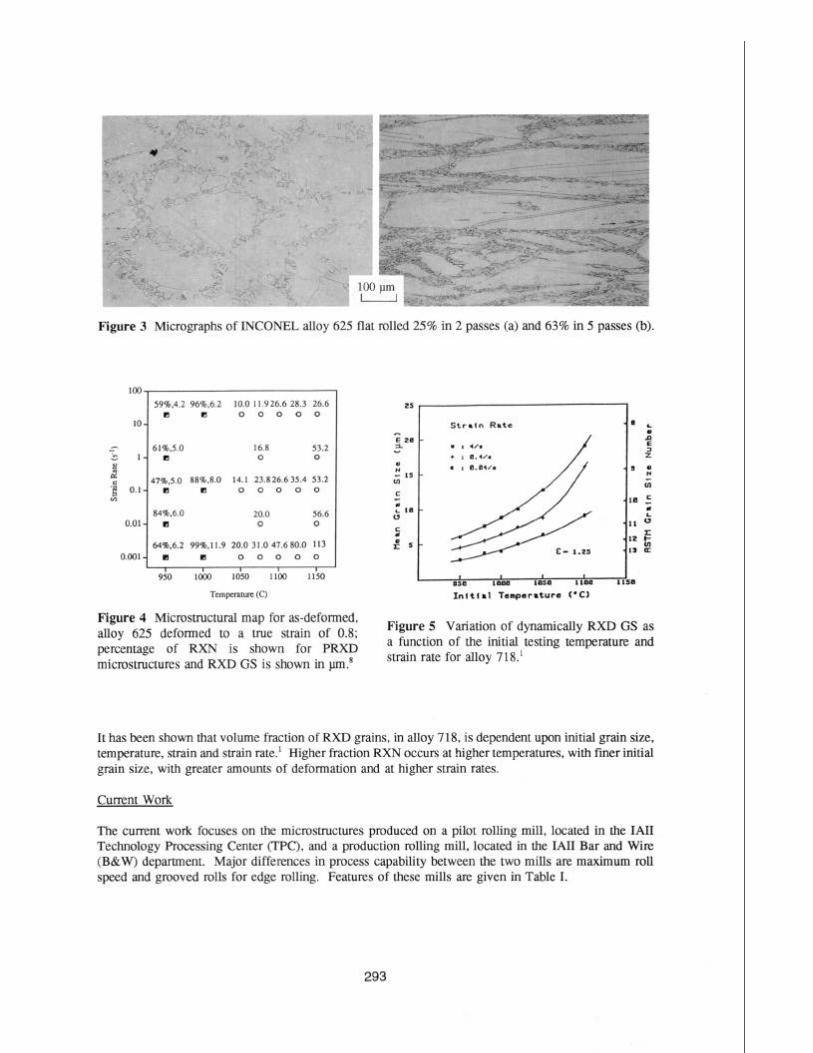
Figure 3 Micrographs of INCONEL alloy 625 flat rolled 25% in 2 passes (a) and 63% in 5 passes (b).
loo
59aO.4.2 966.6.2 10.0 11.926.6 28.3 26.6 q q 0 0 0 0 0
IO-
2 611.5.0 q 16.8
l- 0 53.2 0 u d
2 0.1- 478.5.0 m 88Lb.8.0 q 14.1 0 23.826.635.4 0 0 0 53.2 0
844b.6.0 20.0 56.6 O.Ol- cl 0 0
64Ro.6.2 99&.11.9 20.0 31.0 47.680.0 113 0.001- cl q 0 0 0 0 0
I I I I I 950 locKI 1050 1100 1150
Tcmpcmnnr (C)
Figure 4 Microstructural map for as-deformed, alloy 625 deformed to a true strain of 0.8; percentage of RXN is shown for PRXD microstructures and RXD GS is shown in mn8
2s
E 28 2 D ” LS In c ‘; L III 0
5 es
Stratn Rate
- I , 4,. + I 8.4,. . I B.BWs
A /XI
-0 L :: 5 z
- s z G
-10 = ‘; L
‘11 v
-1.2 F
-I¶ 2
, I , I 1 SSB *ma Iam llBB I IS0
Inlttal Tempsraturs (‘Cl
Figure 5 Variation of dynamically RXD GS as a function of the initial testing temperature and strain rate for alloy 718.’
It has been shown that volume fraction of RXD grains, in alloy 718, is dependent upon initial grain size, temperature, strain and strain rate.’ Higher fraction RXN occurs at higher temperatures, with finer initial grain size, with greater amounts of deformation and at higher strain rates.
Current Work
The current work focuses on the microstructures produced on a pilot rolling mill, located in the IA11 Technology Processing Center (TPC), and a production rolling mill, located in the IA11 Bar and Wire (B&W) department. Major differences in process capability between the two mills arc maximum roll speed and grooved tolls for edge rolling. Features of these mills are given in Table I.
293
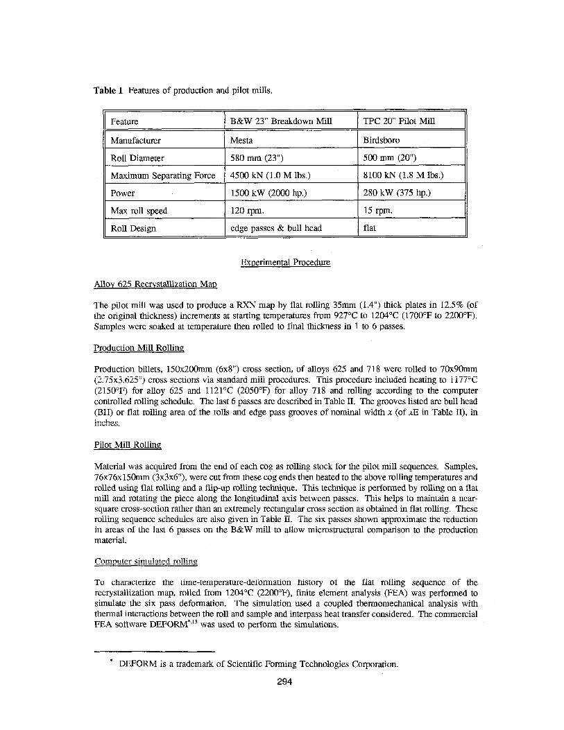
Table I Features of production and pilot mills.
Feature B&W 23” Breakdown Mill TPC 20” Pilot Mill
Manufacturer Mesta Birdsboro
Roll Diameter 580 mm (23”) 500 mm (20”)
Maximum Separating Force 4500 kN (1 .O M lbs.) 8100 kN (1.8 M lbs.)
Power 1500 kW (2000 hp.) 280 kW (375 hp.)
Max roll speed 120 rpm. 15 t-pm.
Roll Design edge passes & bull head flat
Experimental Procedure
Alloy 625 Recrystallization Map
The pilot mill was used to produce a RXN map by flat rolling 35mm (1.4”) thick plates in 12.5% (of the original thickness) increments at starting temperatures from 927°C to 1204°C (1700’F to 2200°F). Samples were soaked at temperature then rolled to final thickness in 1 to 6 passes.
Production Mill Rolling
Production billets, 15Ox200mm (6x8”) cross section, of alloys 625 and 718 were rolled to 7Ox90mm (2.75x3.625”) cross sections via standard mill procedures. This procedure included heating to 1177°C (2150°F) for alloy 625 and 1121’C (2050°F) for alloy 718 and rolling according to the computer controlled rolling schedule. The last 6 passes are described in Table II. The grooves listed are bull head (BH) or flat rolling area of the rolls and edge pass grooves of nominal width x (of XE in Table II), in inches.
Pilot MiIl Rolling
Material was acquired from the end of each cog as rolling stock for the pilot mill sequences. Samples, 76x76x15Omm (3x3x6”), were cut from these cog ends then heated to the above rolling temperatures and rolled using flat rolling and a flip-up rolling technique. This technique is performed by rolling on a flat mill and rotating the piece along the longitudinal axis between passes. This helps to maintain a near- square cross-section rather than an extremely rectangular cross section as obtained in flat rolling. These rolling sequence schedules are also given in Table II. The six passes shown approximate the reduction in areas of the last 6 passes on the B&W mill to allow microstructural comparison to the production material.
Computer simulated rolling
To characterize the time-temperature-deformation history of the flat rolling sequence of the recrystallization map, rolled from 1204’C (22OO”F), finite element analysis (FEA) was performed to simulate the six pass deformation. The simulation used a coupled thermomechanical analysis with thermal interactions between the roll and sample and interpass heat transfer considered. The commercial FEA software DEFORM*‘r3 was used to perform the simulations.
* DEFORM is a trademark of Scientific Forming Technologies Corporation.
294

FEA Formulation and Mesh DEFORM utilizes a flow formulation common in finite element methods for simulating metal flow. The method solves for nodal velocities and models rigid, viscoplastic material behavior. Elastic effects are assumed to be negligible. Four-node quadrilaterial elements were used.
The geometry of flat rolling allows for a plane-strain assumption which is modelled in 2D. The size of the problem is further reduced by assuming planar symmetry at the center of the roll sample. Approximately 500 elements were used to discretize the sample.
Material Properties and Boundarv Conditions Material properties for alloy 625 were obtained from several sources. Elevated temperature flow data, generated by Concurrent Technologies Corporatior?, was used to characterize material flow; thermal properties were obtained from IA11 literature.r4
The heat transfer between the roll and workpiece was characterized by a heat transfer coefficient of 108 kW/m’/K and a constant roll temperature of 200°C. These values were based on a review of other FEA roll models.15,‘6 A convection coefficient of 0.0227 kW/m’/K is used to model heat transfer at surfaces not in contact with the roll. The value is a DEFORM default.
Metallographg
Metallographic work was performed on samples of rolled bar. Grain size measurements were performed utilizing the microstructural comparison method in ASTM El 12 on samples, polished then etched with bromine. Amounts of RXN were estimated.
Table II Bar and Wire production mill and Technology Processing Center pilot mill rolling schedules.
II B&W Mill 15Ox200mm (6x8”) starting size
( Pass No. 1 Groove
6 BH
II 7 I 3.5E
8 8 BH BH
9 9 3E 3E
10 10 BH BH
11 11 2.5E 2.5E -
% Red.
2.1
4.2
13.8
21.7
6.0
19.3
TPC Mill 76x76mm (3x3”) starting size
‘“‘“”
1 67 (2.64) 67 (2.64)
2 64 (2.53) 73 (2.87)
3 60 (2.35) 62 (2.46) 55 (2.18) 58 (2.27)
4 49 (1.94) 65 (2.56) 43 (1.71) 57 (2.25)
5 36 (1.43) 53 (2.09) 49 (1.91)
6 29 (1.16) 52 (2.03) 46 (1.82)
* -- TPC Mill passes containing 2 roll gaps used 2 passes for a single B&W Mill pass, due to mill constraints.
295

Alloy 625 RXN Map Results
According to the FEA model, run for alloy 625 heated to 1204°C (22OO”F), the roll-contact-chill effect caused a 550°C (99O’F) temperature gradient within 2.5mm (0.10”) of the surface in the first pass. This gradient was reduced to approximately 110°C (2OO’F) during the 4 second delay prior to the second pass. Similar roll contact gradients were seen for the other passes though the gradients after the 4 second interpass time reduced each pass until the gradient was less than 10°C (18’F). This decrease in gradient can be attributed to the reduced thickness of the plates. Strain gradients were observed with a peak strain located between 25 and 30% of the thickness from the surface of the plate. The strain gradient increased with each pass while the location of the peak strain remained relatively stationary. This peak strain can be attributed to roll geometry, friction and temperature gradient. There was no microstructural effect associated with this region of higher strain. Figure 6 shows the temperature and strain gradients immediately after the second roll pass, as predicted by DEFORM.
Temperature, OF’
4 0.2
2 0.1 :
0.01, I I i :
t Rolling Direction +
A =lOOO B =I100 c =I200
0.6 D =1300 E =1400
L ::gIj; 0.5
H =I700 I =I600 0.4 J =1900 K =2000 L =2100 0.3 M =2200
0.2
Effective Strain A =0.36 B =0.37 c =0.36 D =0.39 E =0.40 F =0.41 G =0.42 Ii =0.43
0.1
0.0
t Rolling Direction --f
Figure 6 DEFORM predicted temperature and strain profiles immediately following the second pilot mill roll pass.
For the above reasons, the microstructures analyzed in this portion of the current work are from the center of the thickness on the longitudinal surface. Etched samples of the RXN map study showed a large variation in microstructure across the thickness of the specimen, with largely UNRXD surface zones and more RXD centers. The RXN map for alloy 625 under non-isothermal, flat rolling conditions is given in Figure 7.
Alloys 625 and 718 Rolling
Finishing Temperatures The surface finishing temperatures of the materials were measured using an optical pyrometer. Alloy 625 finishing temperatures were 927°C (1700OF) for pilot mill flat rolling and 871’C (1600’F) for flip-up rolling. Alloy 718 finished off the B&W mill at 999°C (183O’F) and off the pilot mill at 904°C (1660°F) for flat rolling and 871°C (1600°F) for flip-up rolling.
Microstructural Evaluations Grain size measurements were made on the starting billets in the annealed condition for alloy 718. As-rolled grain sizes are reported for alloy 625 in Table III and for alloy 718 in Table IV. Data is given for the starting annealed grain size as well as surface and center areas of the production mill rollings and pilot mills trials. Micrographs of as-rolled microstructures for B&W rolling and pilot, flat rolling are given in Figures 8 and 9 for alloy 625 and Figures 10 and 11 for alloy 718.
296

1204 1 ;;.52 / 8;;; 1 8;;‘0 1 8;$1 j 7;;2;2 / 8O;525 (2200)
I I I I I I
1149 1 5% 8.5 1 40% 8 1 5% 11 1 8% 12.5 1 50%* ] 30% * (2100)
1093 4% 12 <5% 10 4% 12 X <5% * X (2000)
1038 4% 11.5 X r5%” 4% * X x
982 1 X ] X X x X X
1 12.5 1 25.0 37.5 50.0 62.5 75.0
( 1800) 1 ii~.:i::i:.ll:i,;,:.:.ii.i.i :I ‘: “. :... :..:: :..... :..
Total Deformation (12.5% / roll pass)
FEA -- FEA predicted rolling temperatures for 1204’C heated samples. * -- Previously RXD grains are twinned (approximately ASTM # 12.5) X -- indicates no RXN
Figure 7 Non-isothermal RXN map for flat rolled alloy 625.
> ’ 8‘ ._
v
i)- *
‘< -’ _’ (I
* \i
i
\
‘I
:““m ” \
Surface Center
Figure 8 Optical micrographs of B&W mill rolled alloy 625 at surface and center locations.
Nowhere on the alloy 625 RXN map, Figure 7, is complete RXN indicated. This is attributed to the significant cooling, from roll contact, of the material as further strain is applied and to the relatively low roll speed of the TPC mill, a strain rate effect as described earlier. Microstructures of the TPC rollings from 76x76mm (3x3”) cross section, Figures 8 and 9, show near full RXN at mid-thickness which indicates that there is a sample size effect between these two rolling sequences. The alloy 625 RXN map also shows a line below which RXN does not occur. This barrier seems to be associated with the RXD GS of ASTM # 12.5 and a rolling temperature of slightly below 1038°C (19OO“F).
297

Table III Microstructural evaluation of the starting and as-rolled samples of INCONEL alloy 625.
INCONEL alloy 625
Starting mat’1 - annealed @ 1177’C (215O”F)/2hrs.
MS ASTM GS
--- ---
Uniform 0.5
As Rolled
Surface Center
MS ASTM GS MS ASTM GS
100% RXD 8 100% RXD 2.5
5% RXD 12 <5% UNRXD RXD GS 11
Uniform 0.5 35% RXD 10.5 100% RXD 11.5
Table IV Microstructural evaluation of the starting and as-rolled samples of INCONEL alloy 718.
Pilot Mill
Pilot Mill
As Rolled
Surface Center
MS ASTM GS MS ASTM GS
100% RXD 9 100% RXD 4.5
50% RXD RXD GS 100% RXD 11 12
20% RXD RXD GS 100% RXD 11 11.5

Surface Center
Figure 9 Optical micrographs of pilot mill rolled alloy 625 at surface and center locations.
Surface Center
Figure 10 Optical micrographs of B&W mill rolled alloy 718 at surface and center locations.
The variation in amount of RXN across the 1149°C rolling temperature attests to the fact that amount of RXN is strongly dependent on many factors and is not readily predicted. The deformation sequence at 1204°C shows that once PRXN occurs it is difficult to recrystallize the UNRXD material even above the RXN temperature. Under further deformation, the temperature decreased from roll contact and the only RXN observed was further refinement of the already RXD areas. Possible contributors to this phenomenon include grain orientation, that most of the strain from subsequent passes ocurrs in the softer RXD grains and that the finer RXD grains recrystallize more readily than the larger UNRXD grains, a grain size effect.
299

Surface Center
Figure 11 Optical micrographs of pilot mill rolled alloy 718 at surface and center locations.
A cross-section / sample size effect has already been discussed with respect to the pilot mill rolling of alloy 625. When comparing the production mill rollings to those performed on the pilot mill there is inevitably a strain rate effect as well. The strain rates on the pilot mill are nearly an order of magnitude lower than those of the production mill. The combination of these two effects are clearly seen when comparing amount of RXN of alloy 625 and 718 rolled on the two mills, Tables III and IV.
Temperature Effects on RXD Grain Size
Alloy 625 In analyzing the alloy 625 hot compression data from Zhao,8 a correlation between RXD GS and deformation temperature is apparent. Figure 12 shows this data plotted in conjunction with RXD GS data from the current work. It is evident from Figure 12 that there are significant differences between the data plotted. These differences may be attributed to the effects of rolling rather than uniaxial compression, differences in chemistry, strain rate effects and the multi-pass history of the materials. Nevertheless, a strong correlation exists.
Allov 718 Mataya3 performed four stroke compression tests, on alloy 718, at a constant true strain rate of 1.0 s-l. Figure 13 shows RXD GS data from Mataya plotted with respect to finishing temperature. Also plotted are alloy 718 grain-size data from the B&W rollings and pilot mill trials. Clearly, RXD GS is strongly dependent on finishing temperature. The regression line associated with data from this work is shifted due to higher strains than in Mataya’s work. The difference in slope of this line is most likely due to grain coarsening during cooling which would be more prevalent at higher temperatures.
Conclusions
Recrystallized grain size of INCONEL alloys 625 and 718 is highly dependent upon finishing temperature for typical rolling operations. There is a large sample size affect on the recrystallization behavior of non-isothermally hot rolled alloy 625. Roll speed can play a large role in the recrystallization behavior of hot rolled alloys 625 and 718. Prediction of amount of recrystallization will continue to be extremely difficult in multi-pass non-isothermal rolling of superalloy 625 and 718.
300

14 ,
St 12
E y 10
2 Production
*
800 900 1000 1100 1200 1300 850 950 1050 1150 1250
Temperature, C + RXN map Rolling from 1204C $ Other Rollings + RXN map Rolling 25% Def. + Zhao Data
Figure 12 Recrystallized grain size as a function of deformation temperature for alloy 625. Data from Zhao8 and the current work.
800 8.50 900 950 1000 1050 1100 1150 1200 1250 Finishing Temperature, C
q Mataya a Pilot Mill + B&W mill
Figure 13 Recrystallized grain size as a function of finishing temperature for alloy 7 18. Data from Mataya3 and the current work.
301

References
1. G. Camus, B. Pieraggi, F. Chevet, “Hot Deformation and Recrystallization in Inconel 718,” Formability and Metallurgical Structure, ed. A.K. Sachdev and J.D. Embury (Warrendale, PA: The Metallurgical Society, 1987), 305-325.
2. M.J. Weis et al., “The Hot Deformation Behavior of an As-Cast Alloy 718 Ingot,” Superalloy 718, ed. E.A. Loria (Warrendale, PA: The Minerals, Metals & Materials Society, 1989), 135-154
3. M.C. Mataya, D.K. Matlock, “Effects of Multiple Reductions on Grain Refinement During Hot Working of Alloy 718,” Superalloy 718, ed. E.A. Loria (Warrendale, PA: The Minerals, Metals & Materials Society, 1989), 155-178.
4. P.J. DiConza, R.R. Biederman, R.P. Singh, “Homogenization and Thermomechanical Processing of Cast Alloy 718,” Superallovs 718, 625, and Various Derivatives, ed. E.A. Loria (Warrendale, PA: The Minerals, Metals & Materials Society, 1991), 161-171.
5. C.I.Garcia et al., “Microstructural Refinement of As-Cast alloy 718 Via Thermomechanical Processing,” Superalloys 718, 625, and Various Derivatives, ed. E.A. Loria (Warrendale, PA: The Minerals, Metals & Materials Society, 1991), 925-941.
6. Concurrent Technologies Corporation, Atlas of Formability Nickelvac 625, National Center for Excellence in Metalworking, Johnstown, PA, 1993.
7. D. Zhao, P.K. Chaudhury, “Effect of Starting Grain Size on As-Deformed Microstructure in High Temperature Deformation of Alloy 718,” Sunerallovs 718, 625, 706 and Various Derivatives, ed. E.A. Loria (Warrendale, PA: The Minerals, Metals & Materials Society, 1994), 303-313.
8. D. Zhao et al. “Flow Behavior of Three 625-Type Alloys During High Temperature Deformation,” Superalloys 718, 625, 706 and Various Derivatives, ed. E.A. Loria (Warrendale, PA: The Minerals, Metals & Materials Society, 1994), 315-329.
9. George E. Dieter, Mechanical Metallurq (McGraw-Hill, 1976), 195.
10. A.J. DeArdo, “Modern Thermomechanical Processing of Microalloyed Steel: A Physical Metallurgy Perspective,” Microalloying ‘95, (Warrendale, PA: Iron and Steel Society, 1995), 15-33.
11. George E. Dieter, Mechanical Metallurgy (McGraw-Hill, 1976), 551.
12. L. Ferrer, B.Pieraggi, J.F. Uginet, “Microstructural Evolution During Thermomechanical Processing of Alloy 625,” Superalloys 718, 625 and Various Derivatives, ed. E.A. Loria (Warrendale, PA: The Minerals, Metals & Materials Society, 1991), 217-228.
13. Scientific Forming Technologies Corporation, DEFORM-PC Primer, Columbus, OH, 1996.
14. INCONEL alloy 625 Technical Bulletin, (Huntington, WV: Into Alloys International, Inc., 1985)
15. C. M. Sellars, “Computer Modelling of Hot-Working Processes,” Materials Science and Technology, 1 (1985), 325-332.
16. W. C. Chen, I. V. Samarasekera, and E. B. Hawbolt, “Fundamental Phenomena Governing Heat Transfer During Rolling,” Metall. Trans. A, 24A (1993), 130’7-1320.