Embed Size (px)
Citation preview

EVlink - QC•••
S1B54439 09/2011
S1
B5
44
39
-00
www.schneider-electric.com
EVlink - QC•••Electric Vehicle Quick Charging StationInstallation Manual
09/2011

The information provided in this documentation contains general descriptions and/or technical character-
istics of the performance of the products contained herein. This documentation is not intended as a
substitute for and is not to be used for determining suitability or reliability of these products for specific
user applications. It is the duty of any such user or integrator to perform the appropriate and complete
risk analysis, evaluation and testing of the products with respect to the relevant specific application or use
thereof. Neither Schneider Electric nor any of its affiliates or subsidiaries shall be responsible or liable for
misuse of the information contained herein. If you have any suggestions for improvements or
amendments or have found errors in this publication, please notify us.
No part of this document may be reproduced in any form or by any means, electronic or mechanical,
including photocopying, without express written permission of Schneider Electric.
All pertinent state, regional, and local safety regulations must be observed when installing and using this
product. For reasons of safety and to help ensure compliance with documented system data, only the
manufacturer should perform repairs to components.
When devices are used for applications with technical safety requirements, the relevant instructions must
be followed.
Failure to use Schneider Electric software or approved software with our hardware products may result
in injury, harm, or improper operating results.
Failure to observe this information can result in injury or equipment damage.
© 2011 Schneider Electric. All rights reserved.
2 S1B54439 09/2011

Table of Contents
Safety Information . . . . . . . . . . . . . . . . . . . . . . . . . . . . . . . . . . . . . . . . . . . . 5About the Book . . . . . . . . . . . . . . . . . . . . . . . . . . . . . . . . . . . . . . . . . . . . . . . 7
Chapter 1 . . . . . . . . . . . . . . . . . . . . . . . . . . . . . . . . . . . . . . . . . . . . . . . . . . . . . . . . . . . . 9Overview of EVlink Quick Charging Stations . . . . . . . . . . . . . . . . . . . . . . . . . . . . . . . . . . . . . . 10
Technical Characteristics . . . . . . . . . . . . . . . . . . . . . . . . . . . . . . . . . . . . . . . . . . . . . . . . . . . . . 15
Access to the Charging Station Compartments . . . . . . . . . . . . . . . . . . . . . . . . . . . . . . . . . . . . 16
Installing the Charging Station . . . . . . . . . . . . . . . . . . . . . . . . . . . . . . . . . . . . . . . . . . . . . . . . . 19
Connecting the Charging Station . . . . . . . . . . . . . . . . . . . . . . . . . . . . . . . . . . . . . . . . . . . . . . . 23
Commissioning . . . . . . . . . . . . . . . . . . . . . . . . . . . . . . . . . . . . . . . . . . . . . . . . . . . . . . . . . . . . . 26
Troubleshooting Assistance . . . . . . . . . . . . . . . . . . . . . . . . . . . . . . . . . . . . . . . . . . . . . . . . . . . 28
Protecting the Environment . . . . . . . . . . . . . . . . . . . . . . . . . . . . . . . . . . . . . . . . . . . . . . . . . . . . 33
S1B54439 09/2011 3

4 S1B54439 09/2011

§
Safety InformationImportant Information
NOTICE
Read these instructions carefully, and look at the equipment to become familiar with the device before
trying to install, operate, or maintain it. The following special messages may appear throughout this
documentation or on the equipment to warn of potential hazards or to call attention to information that
clarifies or simplifies a procedure.
PLEASE NOTE
Electrical equipment should be installed, operated, serviced, and maintained only by qualified personnel.
No responsibility is assumed by Schneider Electric for any consequences arising out of the use of this
material.
A qualified person is one who has skills and knowledge related to the construction and operation of
electrical equipment and its installation, and has received safety training to recognize and avoid the
hazards involved.
S1B54439 09/2011 5

6 S1B54439 09/2011

About the Book
At a Glance
Document Scope
The purpose of this manual is to describe and explain the following operations relating to quick charging stations:
Installing the quick charging station
Electrical connection
Commissioning
Troubleshooting assistance
This manual is aimed at installers of quick charging stations.
NOTE: Commissioning the bank card pay station is not described in this document. For information about
this, please contact Schneider Electric, who supply the charging station.
Validity Note
This manual is valid for quick charging stations and their catalog numbers are listed in the table below.
Quick charging stations differ according to:
Their Human Machine Interface (HMI)
Their user identification system
Their Ethernet communication system
Related Documents
You can download these technical publications and other technical information from our website at
www.schneider-electric.com.
User Comments
We welcome your comments about this document. You can reach us by e-mail at
Catalog Numbers Human Machine Interface User Identification Ethernet Communication
QC001 Touch screen — Wired
QC002 Screen + keypad — Wired
QC003 Touch screen — Wired + wireless
QC004 Screen + keypad — Wired + wireless
QC005 Touch screen RFID tag Wired
QC006 Screen + keypad RFID tag Wired
QC007 Touch screen RFID tag Wired + wireless
QC008 Screen + keypad RFID tag Wired + wireless
QC009 Touch screen Bank card Wired
QC010 Screen + keypad Bank card Wired
QC011 Touch screen Bank card Wired + wireless
QC012 Screen + keypad Bank card Wired + wireless
Title of Documentation Reference Number
EVlink - Installation conditions for charging stations EVlink specific to each electric vehicle
manufacturer
DOCA0007
Instruction sheet Site configuration - EVlink QC••• S1B54009
Instruction sheet Receipt, Handling, Storage - EVlink QC••• S1B54010
S1B54439 09/2011 7

8 S1B54439 09/2011

S1B54439 09/2011
1
EVlink - QC•••
Quick Charging Station Installation Manual
S1B54439 09/2011
What’s in this Chapter?
This chapter contains the following topics:
Topic Page
Overview of EVlink Quick Charging Stations 10
Technical Characteristics 15
Access to the Charging Station Compartments 16
Installing the Charging Station 19
Connecting the Charging Station 23
Commissioning 26
Troubleshooting Assistance 28
Protecting the Environment 33
9

Quick Charging Station Installation Manual
Overview of EVlink Quick Charging Stations
Introduction
Users of electric vehicles may need to recharge their vehicle’s battery very quickly. The 50 kW charging
power of EVlink quick charging stations allows compatible vehicles to be recharged in less than
20 minutes.
Depending on the options selected, EVlink quick charging stations offer the following functions:
User-charging station dialog: touch screen or screen with keypad for displaying the residual charge
and the recharging setpoint
Charging management:
Socket locked during charging
Emergency stop button
Data transmission: Wired connection (Ethernet TCP/IP) or wireless connection for transmitting data
concerning operation, status, activation/deactivation of the charging station, etc.
Bank card pay station, adapted to suit different countries
Authorized user RFID tag reader: management of the list of authorized users by a remote server
Description of DC Quick Charging Stations
A 120 A DC socket
B Wireless communication antenna (depending on the catalog number)
C Human Machine Interface (HMI) (see details on next page)
D Control compartment
E Power compartment
F Emergency stop button
G Pedestal
10 S1B54439 09/2011

Quick Charging Station Installation Manual
Description of the Human Machine Interface
The various HMI parts are shown in the diagrams below.
A LCD touch screen
B RFID tag reader
C Bank card pay station screen + keypad
D Bank card reader
E Paper roll access flap lock
F Ticket exit slot
G Button to go back to the welcome screen
H LCD screen
I Context-sensitive navigation buttons
HMI
Touch screen
HMI
Touch screen
With RFID tag reader
HMI
Touch screen
With bank card pay station
HMI
Screen + keypad
HMI
Screen + keypad
With RFID tag reader
HMI
Screen + keypad
With bank card pay station
S1B54439 09/2011 11

Quick Charging Station Installation Manual
Description of the Control Compartment
The control compartment is accessed via the side doors of the quick charging station. For more
information, see the procedure illustrated in (see page 16).
The control compartment parts are shown in the diagram below. The charging station shown here
includes a bank card pay station and a wireless communication module.
A Wireless communication module (depending on the catalog number)
B PLC
C Ethernet gateway
D Removable terminal blocks for the power compartment fans
E Bank card pay station (depending on the catalog number)
F Bank card pay station printer (depending on the catalog number)
G Document holder containing the wiring diagrams
H Metering panel with energy meter (depending on the catalog number)
I Power connection block
J Main switch
K Control connection block
L Surge arrester
M Earthing braid connection block
12 S1B54439 09/2011

Quick Charging Station Installation Manual
Description of the Power Compartment
The power compartment is accessed via the back of the quick charging station by removing 2 panels. For
more information, see the procedure illustrated in (see page 17).
The power compartment parts are shown in the diagram below.
A DC charging cable outlet
B Smoothing capacitor
C Converter compartment heating and ventilation thermostat
D Converters
E Toroidal chokes
F Control compartment
G DC power supply protection MCBs
H Transformer compartment ventilation thermostat
I Isolation transformer
J Anti-harmonic filter
S1B54439 09/2011 13

Quick Charging Station Installation Manual
Weight and Dimensions
Quick charging stations weigh between 600 and 700 kg depending on the catalog number.
14 S1B54439 09/2011

Quick Charging Station Installation Manual
Technical Characteristics
Environmental Characteristics
Line Supply Characteristics
DC Charging Station Characteristics
Certification
marking
Complies with IEC 61851, Electric vehicle conductive charging system (IEC 61851-1 and
IEC 61851-23).
Complies with IEC 62196, Plugs, socket-outlets, vehicle couplers and vehicle inlets - Electric vehicle
conductive charging system (IEC 62196-1 and IEC 62196-3).
Complies with IEC 61439, Low-voltage switchgear and controlgear assemblies (IEC 61439-2
and IEC 61439-5).
Complies with CHAdeMO protocol.
Complies with European Directive 1999/5/EC (charging station with optional RFID tag reader).
Characteristic Value
Degree of protection IP IP54
Degree of protection IK IK10: charging station
IK3: Human Machine Interface
Operating temperature -30°C to +50°C
Characteristic Value
Connection 400 V AC 3P + neutral
Frequency 50-60 Hz +/- 10%
Earthing system TT or TN
Power 58 kVA
Power factor > 0.95
THDI < 13%
Characteristic Value
Maximum output current 120 A DC
Maximum output voltage 500 V DC
Maximum output power 50 kW
Communication protocol CHAdeMO
Connection socket Yazaki 120 A
Charging mode Mode 4 according to IEC 61851
S1B54439 09/2011 15

Quick Charging Station Installation Manual
Access to the Charging Station Compartments
Access to the Control Compartment
Use the keys supplied with the charging station to open the control compartment:
Bespoke key for the outer door.
Standard key for the inner door.
A
B
16 S1B54439 09/2011

Quick Charging Station Installation Manual
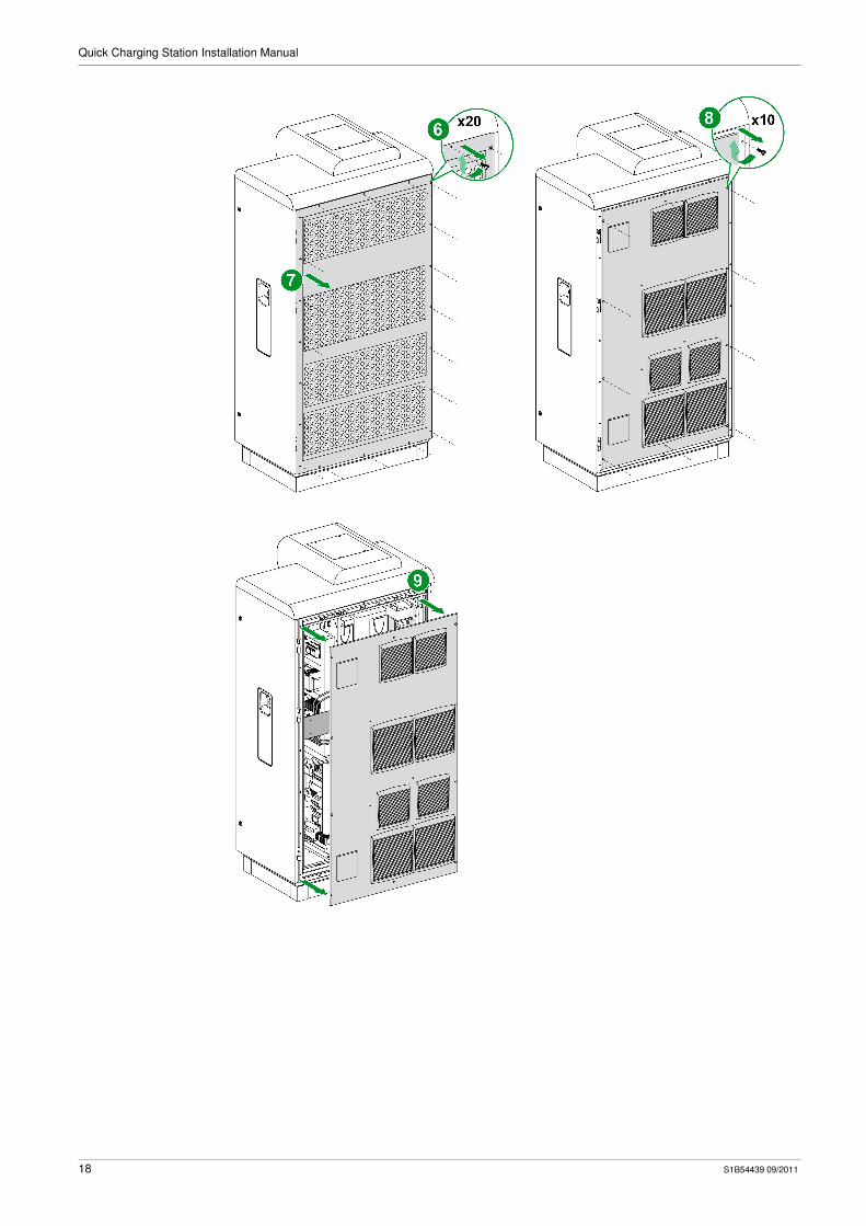
Access to the Power Compartment
2 panels weighing around 15 kg each must be removed in order to gain access to the power
compartment.
DANGERHAZARD OF ELECTRIC SHOCK, EXPLOSION, OR ARC FLASH
Turn off all power supplying this equipment before working on the equipment.
Always use an appropriate voltage detection device to confirm the absence of voltage.
Failure to follow these instructions will result in death or serious injury.
S1B54439 09/2011 17
Quick Charging Station Installation Manual
18 S1B54439 09/2011

Quick Charging Station Installation Manual
Installing the Charging Station
Preparation
Before installing the quick charging station, check the following points:
All site configuration work has been completed and the charging station base (catalog number
VNSCHN100007) is in place.
For more information, please refer to the Instruction sheet Site configuration - EVlink - QC••• (catalog
number S1B54009).
The charging station has been unpacked, with the charging cable socket plugged into its outlet.
For more information, please refer to the Instruction sheet Receipt, handling, storage - EVlink - QC•••
(catalog number S1B54010).
Running Cables in Sheaths
Run the cables in sheaths as shown in the diagram below:
Item Sheath for … Minimum Sheath Diameter Cable Characteristics Minimum Cable Length
A Power cable 110 mm 5 x 35 mm² copper minimum (cross-section to be
defined a/c to cable length)
+ Unsheathed 25 mm² copper braid for
interconnecting mechanical earths
0.5 mm
B Control cable 40 mm 7 x 2.5 mm² (cable obligatory if a remote
emergency stop is used)
0.5 mm
C Communication cable 40 mm Ethernet cable
Telephone cable for the bank card pay station
(depending on the catalog number)
3 m
S1B54439 09/2011 19

Quick Charging Station Installation Manual
Installation Procedure for the Charging Station
Step Action
1 Release the charging station from the transport pallet:
1 and 2 Remove the plastic covers from all 4 corners of the charging station.
3 Undo all 4 M10 screws fixing the charging station to the transport pallet.
2 Clear the passages in the charging station pedestal for handing with a forklift truck:
1 Undo all 4 screws fixing the front and rear fascia strips to the charging station pedestal.
2 Take off the front and rear fascia strips.
3 Open the control compartment (see page 16).
20 S1B54439 09/2011

Quick Charging Station Installation Manual
4 Remove the cable gland plate to free up space for the cable sheaths when installing the charging station on its base.
5 Close the control compartment.
6 Lift the charging station with a forklift truck, setting the forks to their maximum spread because the center of gravity of the
charging station is eccentric.
7 Position the charging station on the base frame.
Step Action
A
S1B54439 09/2011 21

Quick Charging Station Installation Manual
8 Fix the charging station on the base frame with the 4 x M10 nuts and washers supplied.
9 1 Replace both charging station pedestal fascia strips.
2 Tighten all 4 screws fixing the front and rear fascia strips to the charging station pedestal.
3 and 4 Replace the plastic covers on the charging station feet.
10 Open the control compartment to replace the cable gland plate.
For all information concerning the charging station, please refer to the relevant section (see page 23).
11 Close the control compartment.
Step Action
22 S1B54439 09/2011

Quick Charging Station Installation Manual
Connecting the Charging Station
Upstream Protection of the Charging Station Power Circuit
The charging station power circuit must be protected upstream by:
A thermal-magnetic MCB rated 125 A curve D
A 300 mA RCD rated 125 A type A
Connection in the Control Compartment
All the charging station connections are made in the control compartment.
Wiring Diagram
You can find the charging station wiring diagram in the document holder located in the control
compartment.
Please refer to it when connecting the charging station.
DANGERHAZARD OF ELECTRIC SHOCK, EXPLOSION, OR ARC FLASH
Wear suitable personal protective equipment and follow the currently applicable electrical safety
instructions.
Only qualified personnel can install and maintain this equipment.
NEVER work alone.
Turn off all power supplying the charging station before working on it.
Check that all current and voltage sources have been disconnected before carrying out visual
inspections, testing or maintenance work on this equipment. Before closing the doors and refitting
the casing, carefully inspect the working area to ensure that no tools or other items have been left
inside the equipment.
Always use a properly rated voltage sensing device to confirm that all power is off.
If this equipment is to remain in good working order it must be installed, handled and operated
correctly. Failure to follow basic installation instructions can lead to injury and can damage the
charging station.
Failure to follow these instructions will result in death or serious injury.
S1B54439 09/2011 23

Quick Charging Station Installation Manual
Connection Blocks
A Power terminal block
B Earthing braid
C Control terminal block
Power terminal block connection characteristics:
Stripping length: 10 mm
Stranded cable without cable end with a cross-section of 35 mm²
Tightening torque: 2.5...3 N•m
Tool required: size 6 Allen key
Control terminal block connection characteristics:
Stripping length: 8 mm
Stranded cable without cable end with a cross-section of 2.5 mm²
Tightening torque: 0.4...0.6 N•m
Tool required: 2.5 flat screwdriver
Power Terminal Block
The 5 x 35 mm² minimum power cable (cross-section to be defined a/c to cable length) is connected to
the XP terminal block at the bottom of the control compartment.
Power Terminal Block Marking Terminal Assignment
XP1 N
XP2 L1
XP3 L2
XP4 L3
XP5
NOTICECOMPLY WITH THE PHASE ROTATION ORDER
Connect the power cable in accordance with the charging station wiring diagram to ensure the phase
rotation order is as indicated.
Check the phase rotation order with an appropriate tool.
Failure to follow these instructions can result in equipment damage.
24 S1B54439 09/2011
Quick Charging Station Installation Manual
Earthing Braid
Use a 25 mm² unsheathed copper earthing braid to connect the mechanical earths.
The earthing braid has a pierced cable lug to allow passage of a screw. The braid is fixed to the control
compartment frame.
Control Terminal Block
The control connections are connected to the XB terminal block at the bottom of the control compartment.
The control terminal block is used to connect an emergency stop button with 2 NC (normally closed)
contacts.
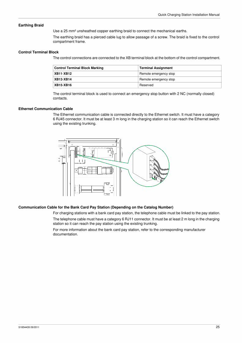
Ethernet Communication Cable
The Ethernet communication cable is connected directly to the Ethernet switch. It must have a category
6 RJ45 connector. It must be at least 3 m long in the charging station so it can reach the Ethernet switch
using the existing trunking.
Communication Cable for the Bank Card Pay Station (Depending on the Catalog Number)
For charging stations with a bank card pay station, the telephone cable must be linked to the pay station.
The telephone cable must have a category 6 RJ11 connector. It must be at least 2 m long in the charging
station so it can reach the pay station using the existing trunking.
For more information about the bank card pay station, refer to the corresponding manufacturer
documentation.
Control Terminal Block Marking Terminal Assignment
XB11-XB12 Remote emergency stop
XB13-XB14 Remote emergency stop
XB15-XB16 Reserved
S1B54439 09/2011 25

Quick Charging Station Installation Manual
Commissioning
Commissioning Procedure
The steps below describe how to commission the charging station. Each step is listed below.
Control Compartment Checks
Turn ON all protection devices.
Retrieve the charging station wiring diagram from the document holder.
Socket Outlet Check
Plug the charging cable socket into its outlet before powering up the charging station. Refer to the socket
usage label.
The socket outlet indicator lights up when the socket is locked.
NOTE: The socket outlet is locked when the charging station is powered up. To unlock the socket outlet,
turn off all power supplying the charging station.
Power-Up
Step Description
1 Control compartment checks
2 Plugging the charging cable socket into its outlet
3 Power-up
Step Action
1 In the control compartment:
Close all the MCBs.
Activate the main switch: The charging station is energized, the self-test sequence starts.
2 On the front of the charging station, check that the screen shows the self-test sequence is running correctly:
The self-test sequence lasts about 30 seconds.
3 At the end of the self-test sequence, if all the tests are successful, the next page is displayed for
10 seconds:
4 The welcome page is then displayed: the charging station is ready for operation.
26 S1B54439 09/2011
Quick Charging Station Installation Manual
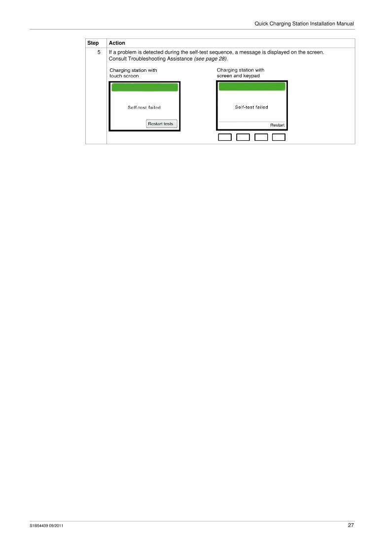
5 If a problem is detected during the self-test sequence, a message is displayed on the screen.
Consult Troubleshooting Assistance (see page 28).
Step Action
S1B54439 09/2011 27

Quick Charging Station Installation Manual
Troubleshooting Assistance
Information Available to the Repairer
The available information is in the form of HMI fault page messages, on the front of the charging station.
If necessary, get in touch with your Schneider Electric contact.
Fault Page
The fault page displays faults detected by the charging station.
The fault page is exited
Automatically, reverting to the welcome page if there is no longer a fault
Manually, by pressing the Back button.
A fault message consists of the following information, presented in the form of a table:
Access to the Fault Page
The table below shows the pages from which you can access the fault page, depending on the type of
charging station.
Column Description
Message Describes the fault if it is a touch screen
Fault number if it is a screen with keypad
See the list of faults (see page 29).
Date Date the fault occurred
Time Time the fault occurred
Page Charging Station with Touch Screen Charging Station with Screen and Keypad
Failure of self-tests
Press Restart tests.
Press the Restart button.
Welcome
Press the top left-hand corner of the screen
for 5 seconds.Press the Back and > buttons simultaneously
for 5 seconds.
Charging station out
of order
Press the top left-hand corner of the screen
for 5 seconds.Press the first and third buttons from the left
simultaneously for 5 seconds.
28 S1B54439 09/2011

Quick Charging Station Installation Manual
Description of the Fault Page
A Messages scroll up
B Messages scroll down
C Display of the previous fault page
D Display of the next fault page
E Acknowledgment of all messages
F Goes back to the previous page, end of consulting fault messages
G Fault message display zone
The color of each fault message indicates the fault status:
List of Faults
The table below lists faults and their consequences:
Charging stops
Charging is prevented from restarting
The fault number appears on the fault page of charging stations with a keypad, the description of the
corresponding fault appears on the fault page of touch screen charging stations.
Touch Screen Screen and Keypad
Message Color Fault Status
Red Active: The fault detected is present and has not been acknowledged.
Green Acknowledged: The fault detected is present and has been acknowledged.
Yellow Not acknowledged: The fault detected has disappeared before being acknowledged.
Fault Number Fault Description Effect on Charging
Charging Stopped Charging Prevented
T-01 Fault PLC CPU √ √
T-02 Nom0200 comm board 1 fault √ √
T-03 Nom0200 comm board 2 fault — —
T-04 Input board fault √ √
T-05 Output board fault √ √
T-06 Fault comm bank card reader — —
T-07 Fault comm RFID reader — —
T-08 Fault comm with GSM&GPRS module — —
T-09 Fault comm with XBT √ √
T-10 Fault comm with Power Meter PM9C √ √
T-11 Discordance conf Bank card payment — —
T-12 Discordance conf Tag payment — —
T-13 CB protect open (QF4) √ √
T-14 CB protect open (QF2 / QF3) √ √
T-15 DC CB open (QF11-13 / QF21-23) √ √
S1B54439 09/2011 29

Quick Charging Station Installation Manual
T-16 Emergency stop (S1) √ √
T-17 Trip lightning protect (F1) √ √
T-18 Trip aux lightning protect (F2) √ √
T-19 CB trip (QF1) √ √
T-20 Trip AC 63A CB (QF2) √ √
T-21 Trip Transfo CB (QF4) √ √
T-22 Trip DC CB (QF11-13/QF21-23) √ √
T-23 Fault insulation (P2) √ √
T-24 Fault temp transfo (BT1) √ √
T-25 Fault ventilation (QFA2) √ √
T-26 Fault On battery power (U1) — —
T-27 Fault Loss 12V (K7) — —
T-28 Fault conv 1 Digital input (U1) √ √
T-29 Fault conv 2 Digital input (U2) √ √
T-30 Fault Bank Terminal — —
T-31 Fault in one of the buttons — —
T-32 Reserved — —
T-33 Fault comm with AC/DC conv-1 √ √
T-34 Fault temp of AC/DC conv-1 √ √
T-35 Over-voltage in AC/DC conv-1 √ √
T-36 Over-current in AC/DC conv-1 √ √
T-37 Loss 1 Voltage AC/DC conv-1 √ √
T-38 Loss 3 Voltage AC/DC conv-1 √ √
T-39 Emergency stop of AC/DC conv-1 √ √
T-40 Fault DPH conv 1 √ √
T-41 Fault BLIC conv 1 √ √
T-42 Fault BTRIP conv 1 √ √
T-43 Fault CPU Watchdog conv 1 √ √
T-44 Fault calibration conv 1 √ √
T-45 Fault current sensor conv 1 √ √
T-46 Fault unknown conv 1 √ √
T-47 Fault softcharge timeout conv 1 √ √
T-48 Fault MODBUS config param conv 1 √ √
T-49 Fault comm with AC/DC conv-2 √ √
T-50 Fault temp of AC/DC conv-2 √ √
T-51 Over-voltage in AC/DC conv-2 √ √
T-52 Over-current in AC/DC conv-2 √ √
T-53 Loss 1 Voltage AC/DC conv-2 √ √
T-54 Loss 3 Voltage AC/DC conv-2 √ √
T-55 Emergency stop of AC/DC conv-2 √ √
T-56 Fault DPH conv 2 √ √
T-57 Fault BLIC conv 2 √ √
T-58 Fault BTRIP conv 2 √ √
T-59 Fault CPU Watchdog conv 2 √ √
T-60 Fault calibration conv 2 √ √
T-61 Fault current sensor conv 2 √ √
T-62 Fault unknown conv 2 √ √
T-63 Fault softcharge timeout conv 2 √ √
T-64 Fault MODBUS config param conv 2 √ √
T-65 Fault battery charger √ √
Fault Number Fault Description Effect on Charging
Charging Stopped Charging Prevented
30 S1B54439 09/2011

Quick Charging Station Installation Manual
Fault Acknowledgement
All faults detected and indicated must be acknowledged manually using the ACK All button on the
screen.
Detected faults disappear from the fault page when the fault has disappeared and been
acknowledged.
The charging station is out of order as long as at least one fault is present and not been acknowledged.
Intervention During the Warranty Period
During the warranty period, any attempt to repair the charging station by anyone other than authorized
Schneider Electric personnel will render the warranty null and void.
If a fault persists, contact the Schneider Electric Customer Care Center.
Schneider Electric Customer Care Center
The Schneider Electric Customer Care Center is available to answer all your technical questions about
EVlink charging stations.
T-66 Fault battery incompatibility √ √
T-67 Fault battery malfunction √ √
T-68 Fault non-zero voltage step 29_3 √ √
T-69 Network volt. out of range +/-10% √ √
T-70 Voltage imbalance √ √
T-71 Current imbalance √ √
T-72 Fault under-voltage √ √
T-73 Fault over-voltage √ √
T-74 Fault comm PWM — —
T-75 Fault PWM Initialization — —
T-76 Bit 1 of 21 PWM register — —
T-77 Bit 6 of 21 PWM register — —
T-78 Bit 3 of 21 PWM register — —
T-79 Bit 5 of 21 PWM register — —
T-80 Bit 2 of 21 PWM register — —
T-81 Bit 4 of 21 PWM register — —
Fault Number Fault Description Effect on Charging
Charging Stopped Charging Prevented
Country Contact Details
Germany Schneider Electric Deutschland
Address: Gothaer Strasse 29, D-40880 Ratingen
Telephone: 0210 240 40
Fax: 0210 240 49256
E-mail: [email protected]
Belgium Schneider Electric Belgium nv/sa
Address: Dieweg 3, 1180 Brussels
Telephone: 02 373 7711
Fax: 02 373 4111
E-mail: [email protected]
Spain Schneider Electric Spain
Address: C/Bac de Roda N×52 - Edificio A, 08019 Barcelona
Telephone: 93 484 3100
Fax: 93 484 3307
E-mail: [email protected]
France Schneider Electric Industries SAS
Address: 35 rue Joseph Monier, 92506 Rueil Malmaison
Telephone: 01 41 29 70 00
Fax: 01 41 29 71 00
E-mail: [email protected]
S1B54439 09/2011 31

Quick Charging Station Installation Manual
You can find the contact details for the Schneider Electric Customer Care Center in other countries on
the website www.schneider-electric.com.
Italy Schneider Electric S.p.A.
Direzione Commerciale Italia
Address:
Via Circonvallazione Est, 1
24040 Stezzano (BG)
Telephone: 3 54 15 11 11
Fax: 3 54 15 28 66
E-mail: [email protected]
United Kingdom Schneider Electric Ltd
Address:
University of Warwick
Science Park
Sir William Lyons Road
Coventry CV4 7EZ
Telephone: 0870 608 8 608
Fax: 0870 608 8 606
E-mail: [email protected]
Country Contact Details
32 S1B54439 09/2011
Quick Charging Station Installation Manual
Protecting the Environment
Recycling Packaging
The packaging materials from this equipment can be recycled. Please help protect the environment by
recycling them in appropriate containers.
Thank you for playing your part in protecting the environment.
End-of-Life Recycling
At end of life, the products in the EVlink range have been optimized to decrease the amount of waste and
valorize the components and materials of the product in the usual end of life treatment process.
The design has been achieved so as components are able to enter the usual end of life treatment
processes as appropriate: depollution if recommended, reuse and/or dismantling if recommended so as
to increase the recycling performances and shredding for separating the rest of materials.
S1B54439 09/2011 33


As standards, specifications and designs change from time to time, please ask for confirmationof the information given in this publication.
S1B54439
Schneider Electric Industries SAS35, rue Joseph MonierCS30323F - 92506 Rueil Malmaison Cedex
www.schneider-electric.com 09/2011