Embed Size (px)
Citation preview
1973 . EVINRUDE~ ~~
& JOHNSON SNOWMOBILE
PART NO. 406187
SECTION 1
INTRODUCTION
SAFETY SYMBOLS
THE PURPOSE OF SAFETY SYMBOLS IS TO ATTRACT YOUR ATTENTION TO POSSIDLE DANGERS. THE SYMBOLS, AND THE .EXPLANATIONS WITH THEM, DESERVE YOUR CAREFUL ATTENTION AND UNDERSTANDING. SAFETY WARNINGS DO NOT, BY THEMSELVES, ELIMINATE ANY DANGER. THE IN-STRUCTIONS OR WARNINGS THEY GIVE ARE NOT SUBSTITUTES FOR PROPER ACCIDENT PREVENTION MEASURES.
SYMBOL
A SAFETY ~WARNING
o PROHIBITED
ONOTE
MEANING
FAILURE TO OBEY A SAFETY WARNING MAY RESULT IN INJURY TO YOU OR TO OTHERS.
WARNS YOU AGAINST AN ACTIVITY WHICH IS, OR MAY BE, ILLEGAL IN YOUR AREA.
ADVISES YOU OF INFORMATION OF INSTRUCTIONS VIT AL TO THE OPERATION OR MAINTENANCE OR YOUR EQUIPMENT.
Before proceeding with any repaij\r adjustments on this snowmobile, see SAFETY WARNINGS on inside front cover and on pages: 6-6, 7-3, 7-11, 7-17, 7-18, 8-2, 9-6, 10-2, 10-3, 10-8, 11-4, 11-6 and 12-5.
INTRODUCTION
SPECIFICATIONS
GENERAL SNOWMOBILE INFORMATION
TROUBLE SHOOTING
TUNE-UP PROCEDURES
FUEL SYSTEM
IGNITION AND ELECTRICAL SYSTEM
1-1
~ __ M_A_NU_A_L_S_T_A_RT_E_R ____________ ~~
~ __ E_NG_I_N_E ____________________ ~ ~ __ D_R_tV_E_T_R_A_IN _________________ ~
STEERING, TRACK AND SUSPENSION
LUBRICATION AND STORAGE II
1- 2
The snow machine has been designed and built for dependable, high performance. It is important to every snow machine owner to be able to receive skilled and thorough service for his vehicle when necessary. It is important to the service dealer to be able to offer the type of skilled service which will maintain the customer's satisfaction.
This manual, together with the regularly issued service bulletins and Parts Catalogs, provide the serviceman with all the literature necessary to service this snowmobile. An effort has been made to produce a manual that will not only serve as a ready reference book for the experienced serviceman, but will also provide more basic information for the guidance of the less experienced man.
The Parts Catalogs contain complete listings of the parts required for replacement. In addition, the exploded views illustrate the correct sequence of all parts. This catalog can be of considerable help as a reference during disassembly and reassembly.
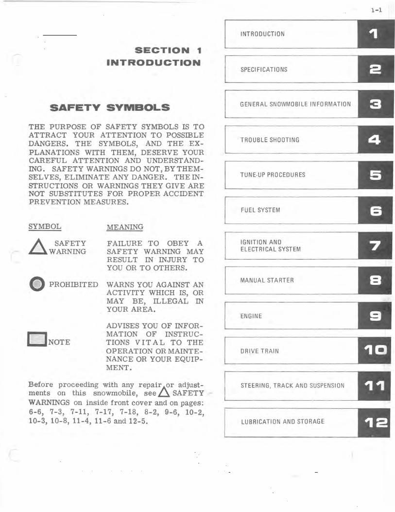
The Section Index on page 1-1 enables the reader to locate quickly any desired section. At the beginning of each Section is a Table of Contents which gives the page number on which each topic begins. This arrangement simplifies locating the desired information within this manual. Section 2 lists complete specifications on the snowmobile. All general information, including 2 cycle engine theory, trouble shooting, and tune up procedures, are given in Sections 3 through 5 of this manual.
Figure 1-1
-
Sections 6 through 11 provide fully illustrated, detailed, step-by- step disassembly and reassembly instructions and adjustment procedures. Section 12 provides lubrication and storage information. In this way, the texts treat each topic separately; theory and practice are not intermixed. This makes it unnecessary for the experienced serviceman to reread discussions of theory along with specific service information. Illustrations placed in the margins provide unimpeded reading of explanatory text, and permit close relationship between illustration and text.
Read this manual carefully to become thoroughly familiar with the procedures described, then keep it readily available in the service shop for use as a reference. If properly used, it will enable the serviceman to give better service to the snowmobile owner, and thereby build and maintain a reputation for reliable service.
This service manual covers all phases of servicing the snowmobile, however, new service situations sometimes arise. If a service question does not appear to be answered in this manual, you are invited to write to the Service Department for additional help. Always be sure to give complete information, including model number and vehicle serial number.
All information, illustrations, and specifications contained in this literature are based on the product information available at the time of publication. The right is reserved to make changes at any time without notice.
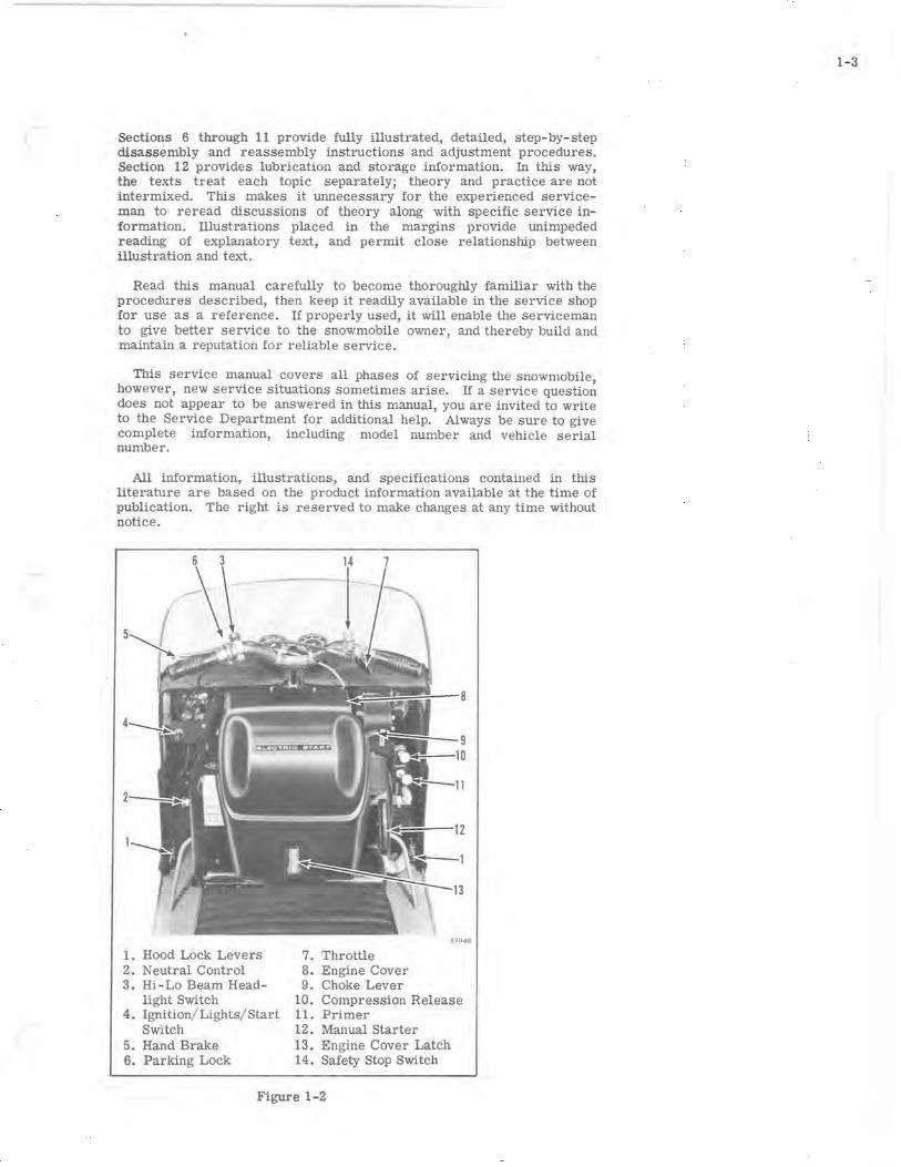
1. Hood Lock Levers 2. Neutral Control 3. Hi-Lo Beam Head
light Switch 4. Ignition/ Lights/ Start
Switch 5. Hand Brake 6. Parking Lock
8
9 ~'---IO
37048
7. Throttle 8. Engine Cover 9. Choke Lever
10. Compression Release 11. Primer 12. Manual Starter 13. Engine Cover Latch 14. Safety Stop Switch
Figure 1-2
1- 3

\ I
) ,
I
2-1
SECTION 2
SPECIFICATIONS
TABLE OF CONTENTS
SPECIFICATIONS. . . . . . . . . . . . . . . . . . 2-2
TORQUE SPECIFICATIONS .........•. 2-3
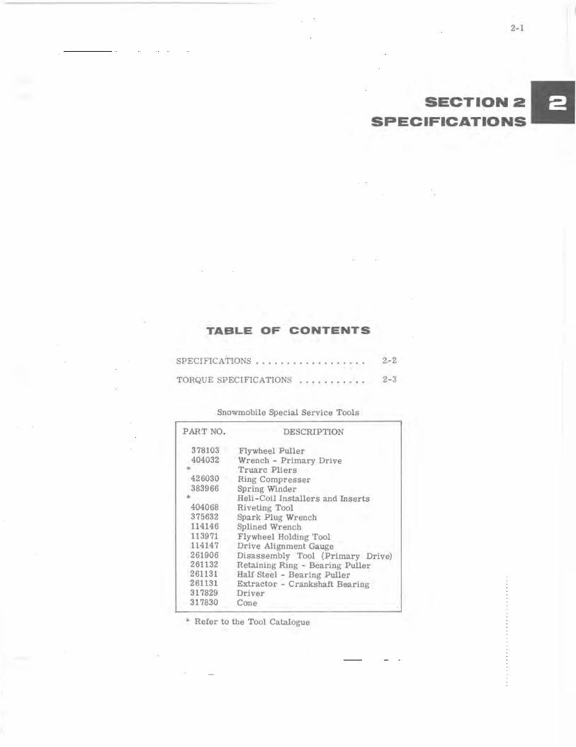
Snowmobile Special Service Tools
PART NO.
378103 404032
*
*
426030 383966
404068 375632 114146 113971 114147 261906 261132 261131 261131 317829 317830
DESCRIPTION
Flywheel Puller Wrench - Primary Drive Truarc Pliers Ring Compresser Spring Winder Heli-Coil Installers and Inserts Riveting Tool Spark Plug Wrench Splined Wrench Flywheel Holding Tool Drive Alignment Gauge Disassembly Tool (Primary Drive) Retaining Ring - Bearing Puller Half Steel - Bearing Puller Extractor - Crankshaft Bearing Driver Cone
* Refer to the Tool Catalogue
2-2
SPECIFICATION S
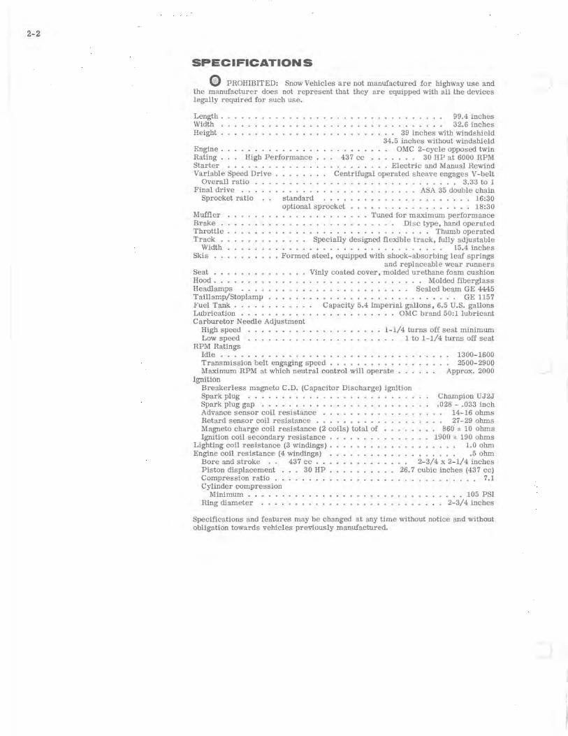
o PROHIBITED: Snow Vehicles are not manufactured for highway use and the manufacturer does not represent that they are equipped with all the devices legally required for such use.
Length. Width Height.
Engine. Rating . High Performance Starter ..... Variable Speed Drive
Overall ratio . Final drive ...
Sprocket ratio standard
437 cc
. . . . . .. 99.4 inches
. . . . . .. 32.6 inches 39 inches with windshield
34.5 inches without windshield OMC 2-cycle opposed twin
. . . . .. 30 HP at 6000 RPM . . . .. .. Electric and Manual Rewind
Centrifugal operated sheave engages V-belt · . . . . . 3.33 to 1 ASA 35 double chain · ....... 16:30
optional sprocket · ....... 18:30 Muffler Brake. Throttle Track.
Tuned for maximum performance · . . . . . Disc type, hand operated · . . . . . . . . . . . . . . Thumb operated
Width Skis
Seat
Specially designed flexible track, fully adjustable · . . . . . . . . . . . . . . . . . .. 15.4 inches
Formed steel, equipped with shock-absorbing leaf springs and replaceable wear runners
Vinly coated cover, molded urethane foam cushion Hood. Headlamps Taillamp/Stoplamp Fuel Tank .....
. . Molded fiberglass . . . . . . . . . . . .. Sealed beam GE 4445 . . . . . . . . . . . . . . . . . . .. GE 1157
Lubrication . . . . Carburetor Needle Adjustment
High speed
Capacity 5.4 Imperial gallons, 6.5 U.S. gallons . . OMC brand 50:1 lubricant
Low speed RPM Ratings
Idle .... Transmission belt engaging speed
1-1/4 turns off seat minimum 1 to 1-1/4 turns off seat
Maximum RPM at which neutral control will operate
1300-1600 2500- 2900
Approx. 2000 Ignition
Breakerless magneto C .D. (Capacitor Discharge) ignition Spark plug ....... . Spark plug gap . . . . . . Advance sensor coil resistance Retard sensor coil resistance . Magneto charge coil resistance (2 coils) total of Ignition coil secondary resistance .
Lighting coil resistance (3 windings) . Engine coil resistance (4 windings)
Bore and stroke 437 cc . . Piston displacement. 30 HP Compression ratiO . . Cylinder compression
Minimum .. Ring diameter
Champion UJ2J .028 - .033 inch
14-16 ohms 27-29 ohms
860 ± 10 ohms 1900 ± 190 ohms
1.0 ohm .5 ohm
2-3/4 x 2- 1/4 inches 26.7 cubic inches (437 cc)
7.1
. . 105 PSI 2-3/4 inches
Specifications and features may be Changed at any time without notice and without obligation towards vehicles previously manufactured.
t
".
(
TORQUE SPECIFICATIONS
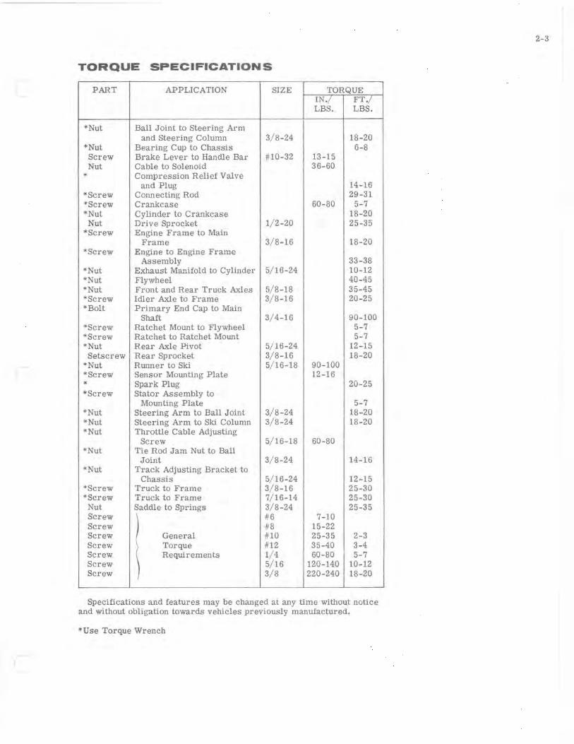
PART APPLICATION SIZE TORQUE IN./ FT./ LBS. LBS.
*Nut Ball Joint to Steering Arm and Steering Column 3/ 8-24 18-20
* Nut Bearing Cup to Chassis 6-8 Screw Brake Lever to Handle Bar #10-32 13-15 Nut Cable to Solenoid 36-60
* Compression Relief Valve and Plug 14-16
*Screw Connecting Rod 29-31 *Screw Crankcase 60-80 5-7 *Nut Cylinder to Crankcase 18-20
Nut Drive Sprocket 1/ 2-20 25-35 *Screw Engine Frame to Main
Frame 3/ 8-16 18-20 *Screw Engine to Engine Frame
Assembly 33-38 *Nut Exhaust Manifold to Cylinder 5/ 16-24 10-12 *Nut Flywheel 40-45 *Nut Front and Rear Truck Axles 5/ 8-18 35-45 *Screw Idler Axle to Frame 3/ 8-16 20-25 * Bolt Primary End Cap to Main
Shaft 3/ 4-16 90-100 *Screw Ratchet Mount to Flywheel 5-7 *Screw Ratchet to Ratchet Mount 5-7 *Nut Rear Axle Pivot 5/16-24 12-15 Setscrew Rear Sprocket 3/ 8-16 18-20
*Nut Runner to Ski 5/ 16-18 90-100 *Screw Sensor Mounting Plate 12-16 * Spark Plug 20-25 *Screw Stator Assembly to
Mounting Plate 5-7 *Nut Steering Arm to Ball Joint 3/ 8-24 18-20 *Nut Steering Arm to Ski Column 3/8-24 18-20 * Nut Throttle Cable Adjusting
Screw 5/ 16-18 60-80 *Nut Tie Rod Jam Nut to Ball
Joint 3/ 8-24 14-16 *Nut Track Adjusting Bracket to
Chassis 5/ 16-24 12-15 *Screw Truck to Frame 3/8 -16 25-30 *Screw Truck to Frame 7/ 16-14 25-30
Nut Saddle to Springs 3/8 -24 25-35 Screw #6 7-10 Screw #8 15-22 Screw General #10 25-35 2-3 Screw Torque #12 35-40 3-4 Screw Requirements 1/ 4 60-80 5-7 Screw ) 5/ 16 120-140 10-12 Screw 3/8 220-240 18-20
Specifications and features may be changed at any time without notice and without obligation towards vehicles previously manufactured.
*Use Torque Wrench
2-3

)
-f
r \
3-1
SECTION 3
GENERAL SNOWMOBILE INFORMATION
TABLE OF CONTENTS
TWO-CYCLE ENGINE OPERATION. • • • • •• 3-2
COMPRESSION • . . . . . • • . • • • . • • • • • • • • 3- 2
CARBURETION ••.••.•..•.••.....•• , 3- 3
IGNITION. . . . . . . • . . • . . . . • . . • . . • . .. 3-4
LIGHTING SYSTEM. . • . • . • . • . • • • • . • •• 3-4
POWER FLOW. . • • • • • . . • • • • • • . • . . • . 3-5 PRIMARY DRIVE. • • • • • • • • • . • . . • • . • 3-5 NEUTRAL CONTROL. • . • . . • • • • • • • .• 3-6 SECONDARY DRIVE. • • . • . • • • • • . . . •• 3-6
II

3-2
POWER STROKE - DOWN
COMBUSTION OF
~x : 0 .. '
)rtj~~~ CONNECTING COUNTER-
ROD BALANCE
AXIS OF ROTATION
171 33
F,gure 3-1
FUEL INTAKE AND EXHAUST
EXHAUST PORT OPEN
Figure 3-2
1713 4
COMPRESSION STROKE - UP
EXHAUST PORT CLOSED
Figure 3-3
17135
TWO CYCLE ENGINE THEORY
An internal combustion engine is one in which fuel is burned inside the engine: a charge of fuel is introduced into a combustion chamber (cylinder) within the engine and ignited. The energy released by the expansion of the burning fuel is converted to torque by the piston, connecting rod, and crankshaft.
Internal combustion engines are classified as either four-cycle or two-cycle engines . The "four" and the "two" refers to the number of piston strokes required to complete a power cycle of intake, compression, power, and exhaust. A piston stroke is piston travel in one direction only; up is one stroke, down is another. In a four-cycle engine, two crankshaft revolutions, or four strokes, are required for each power cycle. In a two-cycle engine only one crankshaft revolution is required per power cycle.
In a two-cycle engine, the ignition of the fuel-air mixture occurs as the piston reaches the top of each stroke. The expansion of gases drives the piston downward (see Figure 3-1). Toward the end of the downward stroke, ports which lead from the cylinder to the exhaust system are uncovered. The expanding exhaust gases flow into these ports, reducing pressure in the cylinder. Immediately after, intake ports are opened. These ports connect the cylinder with the crankcase where a mixture of fuel and air has been developed by carburetion. The downward motion of the piston compresses this mixture and forces it through the intake ports into the cylinder. See Figure 3-2.
The inrushing charge of the fuel - air mixture helps to eject (scavenge) the last of the exhaust gases from the cylinder. At this point, the momentum of the flywheel is required to return the piston to the top of the cylinder. As the piston begins its up-stroke, it closes the intake and exhaust ports and begins to compress the fuel-air mixture trapped in the cylinder. See Figure 3-3. The upward motion of the piston also reduces the pressure in the crankcase. The resulting crankcase suction opens leaf valves which admit a fresh charge of air and fuel from the carburetor into the crankcase, thus preparing for the next power cycle. Near the top of the piston stroke, the compressed fuel-air mixture is ignited, the piston is driven downward, and the power cycle is repeated. At full throttle, this cycle may be repeated more than five thousand times every minute.
COMPRESSION
The pistons and piston rings perform two functions. They compress the mixture of fuel and air in the cylinders before ignition, and receive the force of the power after ignition. For maximum compression, the cylinder must be round and the piston and piston rings correctly fitted to it. The rings must be properly seated in the ring grooves and free to expand against the walls of the cylinder. The rings will not retain the force of combustion if the pistons and cylinder walls are excessively worn, scored, or otherwise damaged, or if the rings become stuck in grooves because of carbon accumulation. Escape of compression past the piston rings is referred to as "blow-by" and is indicated by discoloration or carbon formation on the piston skirt.
Cylinder bores normally wear with operation of the engine. The degree of wear will vary with length of operation, efficiency of lubrication, and general condition of the engine. Excessive cylinder wear results in loose fitting pistons and rings, causing blow-by, loss of compression, loss of power and inefficient performance.
Piston rings are formed in such a manner that when installed on the piston. they bear against the cylinder wall with a light. even pressure. Excessive ring pressure against cylinder wall increases friction, causing high operating temperature, sluggish performance, and abnormal wear or scoring. InsuffiCient pressure allows blow- by, which reduces power, and causes overheating and carbon formation on piston skirt.
Since the ring tends to flex as it follows the cylinder contour during engine operation, clearance or gap must be provided between the ring ends to prevent butting. The ring gap also allows the ring to expand (elongate) as engine temperature rises during operation. Insufficient gap clearance will cause the ring to bend or warp as it flexes and expands; excessive gap clearance will permit loss of compression.
Compression leakage may also occur at spark plugs. A cracked spark plug insulator will cause similar trouble. Although compression is primarily dependent on the piston. rings, and cylinder, these other sources of leakage should be investigated when compression loss is noted.
Compression leakage will occur if the compression relief valve linkage is adjusted with insufficient clearance on the cable ends. The relief valves vent combustion chamber pressure through a by- pass port.
Compression may also be affected by the fuel induction and exhaust systems. Since the fuel vapor is first compressed in the crankcase. leakage here will affect engine performance. Possible trouble spots include leaf valve assemblies , seals between crankcase halves, and crankshaft bearing seals. Exhaust ports which have become clogged because of excessive deposits of carbon will hinder the efficient transfer of exhaust gases.
Excessive carbon build- up on piston heads or elsewhere in the cylinder walls can result in a loss of power.
Following the trouble shooting procedures in Section 4 and the recommended tune-up procedures given in Section 5 will assure that all areas affecting fuel induction, compression, and exhaust will be considered as part of every trouble shooting procedure. An engine with low or uneven compression cannot be successfully tuned for peak performance. It is essential that improper compression be corrected before proceeding with an engine tune- up.
CARBURETION Gasoline , in its liquid state. burns relatively slowly with an even
flame. However, when gaSOline is combined with air to form a vapor, the mixture becomes highly inflammable and burns with an explosive effect. To obtain best results, the fuel and air must be correctly proportioned and thoroughly mixed. It is the function of the carburetor to accomplish this.
Gasoline vapor will burn when mixed with air in a proportion from 12:1 to 18:1 by weight. Mixtures of different proportions are required for different purposes. Idling requires a relatively rich mixture; a leaner mixture is desirable for maximum economy under normal load conditions; avoid lean mixtures for high speed operation. The carburetor is designed to deliver the correct proportion of fuel and air to the engine for these various conditions.
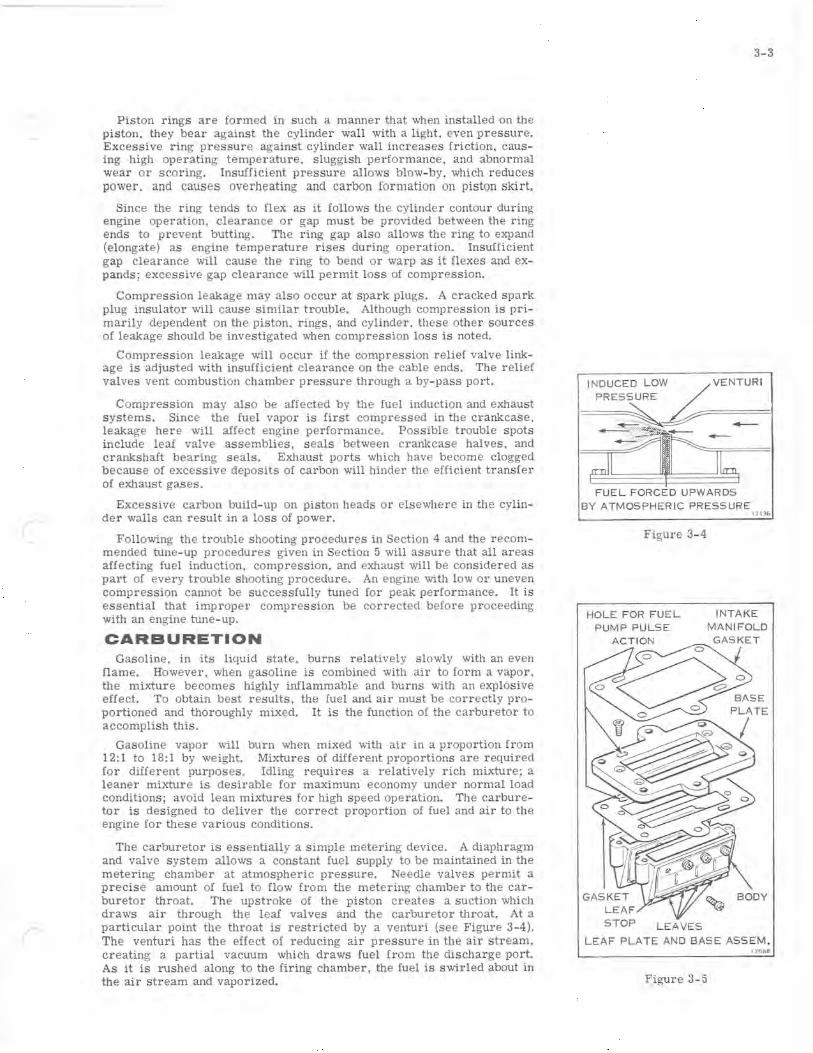
The carburetor is essentially a simple metering device. A diaphragm and valve system allows a constant fuel supply to be maintained in the metering chamber at atmospheric pressure. Needle valves permit a precise amount of fuel to flow from the metering chamber to the carburetor throat. The upstroke of the piston creates a suction which draws air through the leaf valves and the carburetor throat. At a particular point the throat is restricted by a venturi (see Figure 3-4). The venturi has the effect of reducing air pressure in the air stream, creating a partial vacuum which draws fuel from the discharge port. As it is rushed along to the firing chamber, the fuel is swirled about in the air stream and vaporized.
FUEL FORCED UPWARDS BY ATMOSPHERIC PRESSURE
Figure 3- 4
3-3
17136
HOL E FOR FUEL INTAKE PUMP PULSE MANIFOLD
LEAVES
LEAF PLATE AND BASE ASSEM . 17088
Figure 3-5

3-4
GROUND ELECTRODE CENTER
Figure 3-6
REFERENCE -
P - PERMANENT MAGNET N - NORTH POLE SHOE S - SOUTH POLE SHOE F - FLYWHEEL
1713R
C - LAMINATED COIL CORE 17 137
Figure 3-7
A throttle or butterfly valve in the throat regulates the amount of air drawn through the carburetor. To vary the speed of the engine, the throttle opens or closes. regulating the amount of fuel-air mixture drawn into the engine.
A richer fuel mixture is required for starting a cold engine. A second shutter. called a choke. is placed into the throat forward of the jets, to restrict the flow of air. When the choke shutter is closed, more gasoline and less air is allowed into the air stream resulting in a richer fuel-air mixture. When normal operating temperature is reached, the choke is opened and the standard ratio of gasoline and air allowed to flow from the carburetor.
The system which controls the intake of the fuel-air mixture in the two cycle engine consists of a set of leaf valves which serve the same purpose as the intake valves on a four cycle engine. The leaf valves are thin, flexible metal strips mounted between the carburetor intake manifold and crankcase.
When the piston is on the up-stroke. it creates a partial vacuum in the crankcase. Atmospheric pressure forces the leaves away from the body (see Figure 3- 5). opening the passage between the carburetor and crankcase. When the piston is on the down-stroke, it compresses the crankcase charge. forCing the leaves against the passage opening, and sealing off the crankcase from the carburetor. Since the opening and closing may occur in excess of five thousand times per minute, the leaves must be thin and flexible.
IGNITION The magneto capacitor discharge (C. D.) ignition system generates a
high voltage electric current which jumps the spark plug gap within the cylinder and thus ignites the compressed fuel-air mixture in the cylinder. See Figure 3-6.
This system is made up of the following major components:
1. Flywheel assembly 4. Sensor plate assembly 2. Sensor rotor 5. Power Pack I assembly 3. Stator and charge coil assembly 6. Ignition coils
The following sequence of events will illustrate how this system works.
The flywheel rotates around the stator and charge coil assembly. (See Figure 3-7.) The magnets in the flywheel and the (2) charge coils generate a voltage. This voltage (AC) flows into the Power Pack 1. Here it is changed to DC and stored in a capacitor. At the same time the sensor rotor rotates by the sensor coils and a smaller AC voltage is generated. This smaller voltage flows into the Power Pack I and causes an electronic switch in the Power Pack I to turn on allowing the voltage stored in the capaCitor to discharge into the primary of the ignition coils.
One thing to note in this system is that there are two sensor coils. Below the idle RPM range and up to apprOXimately 900 RPM, the retard sensor turns on the electronic switch in the Power Pack 1. At RPMs over 900 the advance sensor coil generates enough voltage to turn on the electronic switch in the Power Pack I before the retard sensor does. So, we have an automatic electronic advance built into the system.
The ignition coil primaries receive the voltage from the Power Pack I, building up the secondary voltage high enough to fire across the spark plug gaps.
LIGHTING SYSTEM
The alternator coils produce alternation current which changes in frequency and voltage in proportion to the engine speed.
)
.-, This alternating current output is converted to direct current by a diode bridge rectifier and used to charge the battery. Direct current from the battery is then used to power the headlights and taillights, and the electric starter motor.
The alternator output is automatically increased to maximum charge when lamps are turned on.
POWER FLOW
The transmission assembly transmits power from the engine to the front axle which propels the vehicle along the track. The primary sheave assembly is attached directly to the crankshaft. The secondary sheave assembly has its own mounting pedestal and is larger in diameter than the primary sheave assembly. The two are cormected by a transmission belt.
PRIMARY DRIVE
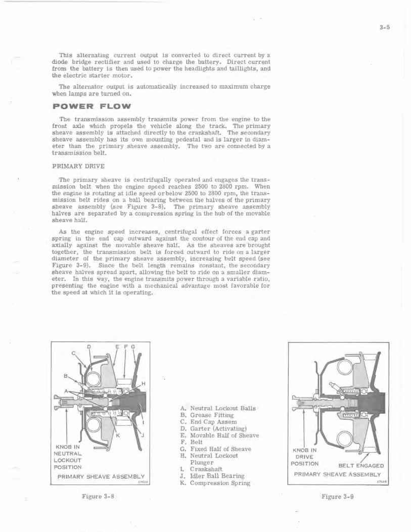
The primary sheave is centrifugally operated and engages the transmission belt when the engine speed reaches 2500 to 2800 rpm. When the engine is rotating at idle speed orbelow 2500 to 2800 rpm, the transmission belt rides on a ball bearing between the halves of the primary sheave assembly (sze Figure 3-8). The primary sheave assembly halves are separated by a compression spring in the hub of the movable sheave half.
As the engine speed increases, centrifugal effect forces a garter spring in the end cap outward against the contour of the end cap and axially against the movable sheave half. As the sheaves are brought together, the transmission belt is forced outward to ride on a larger diameter of the primary sheave assembly, increasing belt speed (see Figure 3-9). Since the belt length remains constant, the secondary sheave halves spread apart, allowing the belt to ride on a smaller diameter. In this way, the engine transmits power through a variable ratio, presenting the engine with a mechanical advantage most favorable for the speed at which it is operating.
NEUTRAL LOCKOUT POSITION
PRIMARY SHEAVE ASSEMBLY 37028
Figure 3-8
A. Neutral Lockout Balls B. Grease Fitting C. End Cap Assem D. Garter (Activating) E. Movable Half of Sheave F. Belt G. Fixed Half of Sheave H. Neutral Lockout
Plunger 1. Crankshaft J. Idler Ball Bearing K. Compression Spring
DRIVE POSITION
3-5
BELT ENGAGED
PRIMARY SHEAVE ASSEMBLY 3 702.9
Figure 3-9
3-6
NEUTRAL CONTROL A neutral control mechanism is used to prevent the drive from engag
ing during starting, warm-up period, and idle. When the neutral lockout plunger is actuated, a cone on the end of the plunger raises two balls through the splines of the primary sheave assembly and into the path of the movable sheave half, preventing it from engaging the belt. The neutral control will operate only when the engine is at idle speed.
SECONDARY DRIVE The secondary drive mechanism incorporates a torque sensing device
that detects the need for more power for steep inclindes or deep snow. The mechanism immediately forces the secondary sheaves closer together to increase the drive ratio and provide a higher torque to the drive chain and track.
The drive ratio varies from 3.3 to 1 in low to .97 to 1 in high which yields an overall drive range of approximately 3.33 to 1. Power is transmitted from the secondary sheave assembly through a drive chain to the front axle.
The ratio between the secondary sheave and the front axle is 16:30. An optional upper sprocket is available to change this ratio to 18:30 for higher speed driving.

4 - 1
SECTION 4
TROUBLE SHOOTING
TABLE OF CONTENTS
DESCRIPTION. . . • . . . • • . • . . • • • • • . . • • 4-2
TROUBLE SHOOTING PROCEDURES. • • . • . 4- 3 STARTING . • . • . . . . . . • . • • . • • . • • •• 4-3 STARTING - MANUAL STARTER. . . . . . . 4-4 STARTING - ELECTRIC STARTER . . . . •. 4-4 RUNNING - LOW SPEED ONLY. • . . • • •• 4- 4 RUNNING - HIGH SPEED ONLY. • . • . • •• 4-4 RUNNING - HIGH AND LOW SPEED. . . •. 4- 5
4-2
DESCRIPTION
This section provides trouble shooting procedures for the snow machine. Steps to be followed in determining causes of unsatisfactory performance are outlined.
Being able to locate the cause of trouble in an improperly operating snow machine is as important as being able to correct the trouble. A systematic approach to trouble shooting is important if the trouble is to be located and identified in minimum time.
Any service operation can be broken down into three steps:
1. Identifying the problem
2. Determining the cause of the problem, and
3. Correcting the problem.
Familiarity with the factors which affect two-cycle engine performance is important in making a correct service diagnosis. Factors which affect engine performance include the quality of the fuel and fuel mixtures. compression, ignition, and proper drive system adjustment. Engine theory, compression, carburetion. ignition and power flow are discussed in Section 3. Correct fuel mixture for this snowmobile is outlined on the inside front cover, and fuel blending is discussed in Section 12. Familiarity with factors which contribute to abnormal performance of an engine are similarly helpful. The skilled mechanic's experience is a great asset here.
TROUBLE SHOOTING PROCEDURES
Trouble shooting to determine the cause of any operating problem may be broken down into the following steps:
a. Obtaining an accurate description of the trouble.
b. Preliminary inspection.
c. Use of Trouble Check Chart to analyze engine performance.
An accurate description of the trouble is essential for trouble shooting. The owner' s comments may provide valuable information which will serve as a clue to the cause of the problem.
A preliminary inspection should include the fOllowing checks.
a. Correct spark plugs
b. Throttle linkage properly adjusted
c. Tank filled with fresh . clean fuel of the proper mixture
d. Spark at each spark plug
e. Carburetor adjusted correctly
f. Compression. Turn flywheel by hand or with recoil starter. If compression is present, it can be felt when turning through one complete revolution of the flywheel. If little or no compression exists in both cylinders. engine will spin very easily.
STARTING
1. Hard to start or won't start
a. Empty gas tank
b. Incorrect gas-lubri cant ratio
c. Old fuel, o r water or dirt in fuel system
d. Fuel line improperly connected
e. Fuel line kinked or severely pinched
f. Engine not primed
g. Clogged fuel line or fuel filter
h. Clogged check valve
i. Carburetor adjustments too lean
j. Low speed needle bent o r bowed
k. Engine flooded
4-3
1. Leaf valves not functioning properly
m. Faulty gaskets
n. Spark plugs fouled, improperly gapped, dirty or broken
o. Loose or broken wire or frayed insulation in ignition system wiring
p. Sheared sensor hub key
q. Faulty coils
r. Key switch, connector or grounded switch wire
s. Binding in engine
t. Faulty sensor, charge COils, Power Pack I or connecting wiring.
2. Engine won't turn over
a. Cylinder wall corrosion, s'eized piston or bearing
b. Engine improperly assembled after repair
3. Cranks over extremely easily
a. Spark plug(s) loose
b. Cylinder or pistons scored
c. Rings worn or carboned
d. Faulty crankcase gasket or crankseal(s)
e. Broken or damaged leaf valves
4. Won't start, but kicks back and backfires
a. Leaf valves broken or not seating
b. Sensor leads on Power Pack I terminals #6 & #8 reversed
c. Timing out of adjustment (check sensor hub key)
d. Advance sensor faulty or out of adjustment
e. Power Pack I faulty
5. No spark one cylinder
a. Faulty ignition coil, wire, or connections
b. Faulty Power Pack I
4-4
6. N() sEark both cylinders
a. Faulty charge coil
b. Faulty sensor coil
c. Faulty Power Pack I
d. Grounded ignition switch and/or wire
e. Flywheel not magnetized
f. Faulty ignition coils or leads
7. Weak spark both cylinders
a. Ignition switch or connection leakage
b. Weak charge coils
c. Weak Power Pack I output
d. Weak ignition coils
8. Engine can be started by using primer, but dies out when primer is not used .
a. Fuel pump inoperative
b. Fuel line or check valve between primer pick -up and carburetor clogged
c. Fuel filter screen in fuel pump or carburetor inlet screen clogged
d. Leaf block base plate reversed
e. Carburetor inoperative
ST ARTING - MANUAL STARTER
1. Manual starter pulls out. but starter does not engage flywheel
a. Friction spring bent or burred
b. Grease on pawls or spring
c. Pawls bent or burred
d. Pawls frozen (water) in place
2. Starter rope does not return
a. Recoil spring broken or binding
b. Starter housing bent
c. Loose or misSing parts
d. Grease on pawls or spring
3. Clattering manual starter
a. Friction ring bent or burred
b. Starter housing bent
c. Grease on pawls or spring
d. Dry starter spindle
STARTING - ELECTRIC STARTER
1. Starter cranks too slowly
a. Weak battery
b. Loose or corroded connections or ground connection
c. Starter belt slipping
d. Faulty starter solenoid or solenoid wiring
e. Worn armature brushes or spring
f. Faulty field or armature (shorted or open windings)
2. Starter will not crank engine
a. Weak battery
b. Loose or corroded connections or ground
c. Broken wire in harness or connector
d. Faulty ignition key switch
e. Faulty starter solenoid or solenoid wiring
f. Moisture in starter motor
g. Broken or worn brushes or broken brush spring
h. Faulty field or armature (shorted or open windings)
RUNNING - LOW SPEED ONLY
1. Low speed miss
a. Incorrect gas - lubricant ratio
b. Carburetor idle adjustment too lean or too rich
c. Leaf valve standing open or preloaded shut
d. Spark plugs improperly gapped. dirty, or broken
e. Loose or broken ignition coil wires
f. Spark plug terminal loose
g. Weak coil
h. Cylinder gasket or leaf plate gasket damaged
i. Leaki ng crankcase gaskets or crankshaft seals
j. Arcing around ignition coils or arcing in ignition switch
k. Loose connections or intermittent grounding of leads in the: ignition coil. Power Pack I, charge coils. sensor coils, and ignition switch
RUNNING - HIGH SPEED ONLY
1. High speed miss
a. Water in fuel
b. Carburetor inlet needle sticking
c. Spark plugs improperly gapped or dirty, cracked insulator
d. Ignition coil - weak output
e. Engine improperly timed
f. Exhaust ports or exhaust system carboned
g. Combustion chambers carboned or fouled
h. Arcing around ignition coils or arcing in ignition switch
i. Loose connections or intermittent grounding of leads in the: ignition coil, Power Pack I, charge coils, sensor coils. and ignition switch
2. Poor acceleration. top rpm is low
a. Incorrect gas - lubricant ratio
b. Old fuel
c. Fuel hoses plugged or kinked
d. Fuel filter restricted (fuel pump or carburetor)
e. Fuel pump or pulse line faulty
L Incorrect carburetor adjustments
g. Inlet needle and seat worn or sticky
h. Timing out of adjustment
i. Spark plugs dirty or improperly gapped
j. Loose, broken, or badly insulated high sion leads
k. Ignition coil weak output
ten-
1. Leaf valves not properly seated. or broken
m. Piston rings stuck or piston scored
4- 5
n. Excessive carbon on pistons and cylinder head
o. Compression relief valve improperly adjusted or faulty
p. Exhaust ports or exhaust system carboned up
q. Charge coils, Power Pack I faulty
3. Idles well, but acceleration poor, dies at full throttle
a. Fuel lines or passages obstructed
b. Fuel filter clogged
c. Faulty fuel pump or pulse line
d. Fuel cap vent clogged
e. High speed nozzle or jet clogged
f. Dirt or packing behind needles and seats
g. Choke partly closed
h. High speed needle set too lean
i. Advance sensor faulty
j. Advance and retard sensor leads interchanged on Power Pack 1.
4. Engine runs at high speed only by using hand primer
a. Fuel lines or passages obstructed
b. Fuel line leaks or fuel filter obstructed
c. Fuel pump not supplying enough fuel
d. Leaf block base plate reversed
e. Dirt or packing behind needles or seats
f. Carburetor adjustments
g. Fuel cap vent clogged
RUNNING - HIGH AND LOW SPEED
1. Engine overheats
a. Incorrect gas - lubricant ratio or improperly mixed fuel
b. Engine not assembled correctly during repair (binding)
c. Lean mixture (carburetor adjustment)
d. Cooling fan obstructed
4-6
2. Engine seizes (stops suddenly)
a. No lubricant in gas, or no fuel
b. Rod or main bearing seized
c. Cylinder or piston scored or seized
3. Engine knocks excessively
a. Incorrect gas - lubricant ratio
b. Flywheel loose
c. Crankshaft end play excessive
d. Carbon in combustion chambers and exhaust ports. or on pistons
e. Worn or loose bearings, or pistons
f. Loose assemblies. bolts. or screws
g. Manual starter not centered
4. Excessive fuel consumption
a. Hole in fuel pump diaphragm
b. Carburetor casting porous
c. Deteriorated carburetor gaskets
d. Carburetor improperly adjusted
e. Hole in metering diaphragm
5. Vibrates excessively or runs rough and smokes
a. Too much lubricant mixed with gas
b. Idle or high speed needles too rich
c. Air passage to carburetor obstructed
d. Faulty ignition
6. No power under heavy load
a. Faulty carburetion
b. Faulty ignition coil(s)
c. Ignition timing off
d. Carbon build-up on piston head, exhaust ports, or exhaust system
e. Cylinder scored or rings stuck
f. Compression relief valve open
g. High speed adjustment lean
h. Spark plugs fouled or misfiring
7. Engine misfires
a. Spark plugs dirty, fouled
b. Grounding or leakage of secondary leads
c. Ignition coil faulty
d. Grounding or leakage of ignition switch, switch wire or connection
e. Loose connections at: ignition coils, charge coils, Power Pack I, and sensor coils
8. Spark on only one cylinder
a. Ignition coils
b. Power Pack I output
9. Engine will start and idle, but quits on accelerating
a. Check advance sensor coil and leads
b. Check Power Pack I output
c. Check timing
(
5-1
SECTION 5 TUNE-UP PROCEDURES
TABLE OF CONTENTS
DESCRIPTION. . . • . • . • • • • • • . • • • • • • .. 5-2
FACTORS AFFECTING PERFORMANCE. . .. 5-2 FUEL SYSTEM. • . • • . . • . • • • • . • • • •. 5-2 IGNITION SYSTEM. . . • • • . • • • • . • • • • • 5-2 COMPRESSION • . . • • • . • • • • • • • • . • •• 5- 2
NEW VEHICLE DELIVERY. • . • • • . . . • . •• 5-3
TUNE-UP PROCEDURES • • • . • • • • • . • • • • 5-3
COMPRESSION CHECK. . • • • . • • . • • • • • •. 5- 5
IGNITION TIMING CHECK. • • • • • . • • . • • .. 5-5
COMPRESSION RELEASE VALVE ADJUSTMENT. • . . • • • • . • . • • • • • . • • •• 5- 5
CARBURETOR ADJUSTMENTS. • • • • . . . • • 5-5 HIGH SPEED NEEDLE VALVE. • • • • • • • • 5-5 LOW SPEED NEEDLE VALVE. • • • • • • •• 5-6 IDLE ADJUSTMENT SCREW. • • . • • • • •• 5-6
SPARK PLUGS • • • • • • . • • • • • • • • • • • • •. 5-6
5-2
DESCRIPTION
The purpose of a tune-up is to restore power and performance which have been lost through wear or deterioration of one or more parts of the snow machine. The successful completion of a tune-up depends on an understanding of principles of two-cycle engine operation. and a familiarity with factors affecting performance. This section gives complete tune-up procedures. Refer to Section 3 for principles of operation, and to Section 4 for trouble shooting procedures . Lubrication procedures and instructions for storage are included in Section 12.
FACTORS AFFECTING PERFORMANCE
In the normal operation of an engine, the operator may not be fully aware of the decrease in performance which takes place slowly over a long period of time. Economical. trouble-free operation can best be assured if a complete tune-up is performed at least once each year, preferably at the start of the season.
It is seldom advisable to attempt to improve performance by correcting one or two items only. Time will be saved and more lasting results obtained by following a definite and thorough procedure of analysis and by correcting all items affecting power and performance.
FUEL SYSTEM
A fresh fuel mixture, with the correct ratio of lubricant and gasoline, is necessary for peak engine preformance. The tank should be removed, emptied of old fuel, rinsed out, installed and refilled with a fresh supply at the beginning of the season and at every tune-up. A stale fuel mixture may cause hard starting, stalling, and faulty operation. Inadequate fuel delivery, as the result of a faulty fuel pump or clogged filter, will affect high-speed performance. Incorrect carburetor needle adjustments may cause operating difficulties at any speed. Faulty choke operation or incorrect use of the manual choke by the operator may cause hard starting, rough running, or poor fuel economy. See Section 3 for a discussion on carburetion.
IGNITION SYSTEM
A good ignition system is of p:rime importance for peak engine performance. A weak spark. which may be the result of faulty ignition system components, will cause hard starting, misfiring, or poor high .. speed performance. The spark plugs and ignition system components are frequently checked first in a tune-up because of their importance to the operation of the engine. See Section 3 for a discussion on ignition theory. and Section 7 for complete ignition system analysis.
COMPRESSION
Compression must be well sealed by the piston and piston rings in the cylinder to realize maximum power and performance. See Figure 5-1. A compression check is important because an engine with low or uneven compression cannot be tuned successfully to give peak performance. It is essential that compression be checked before proceeding with an engine tune-up.
J ~
I
i . I
liZ'
NEW VEHICLE DELIVERY Complete instructions for putting a new snowmobile into operation
are included in the Owner's Manual and assembly instruction packed with each snowmobile. Be sure the customer receives this manual and understancts the instructions given in it. The following list is a reminder of important things to check when putting a new snowmobile into operation.
a . Be surf' spark plugs are installed and tightened securely with spark plug gaskets in place.
b. Be sur e spark plug wires are securely attached to spark plug terminals.
c . Be sure the correct gasoline and lubricant mixture is used. Pour mixture into tank through a fine mesh strainer.
d. Caution the customer not to operate a new engine at continuous full power until at least one tankful of fuel has been used. During this time, short periods of full power may be used. Instruct the customer to follow the break-in procedure described in the Owner's Manual.
e. Be sure that the customer understands how to operate the engine correctly. especially such things as the neutral control, compression release, choke and electric starting.
TUNE-UP PROCEDURES
Components which affect engine power and performance can be divided into three groups, namely:
1. items affecting compression.
2. items affecting ignition.
3. items affecting carburetion .
Any tune-up procedure should cover these groups in the order given. Correction of items affecting carburetion should not be attempted until all items affecting compression and ignition have been corrected satisfactorily. Attempts to overcome compression or ignition system deficiencies by altering carburetor settings will result in poor overall performance or increased fuel consumption. This section covers only those parts of a tune-up which invoh'e adjustments. cleaning, and checking for performance. Trouble shooting procedures are covered in Section 4. Repair and replacement of parts, as determined through trouble shooting. is covered in Sections 6 through 11.
a . Test run vehicle. checking particularly the following:
1. Neutral control
Call transmission be locked in neutral when machine is at rest and engine at idle speed?
5-3
5-4
2. Function of compression release
3. Function of brake
4. Engine performance
5. Ski alignment and handling
6. After running snowmobile. reduce engine speed to idle and pull neutral control knob out to lock transmission in neutral. Accelerate engine to see if transmission is in neutral. Neutral control cannot be engaged above approximately 2000 rpm.
b. Check compression, see page 5-5.
c. If engine knocks, check for loose flywheel. Remove manual starter and fan housing (see Section 8). Rock flywheel back and forth and listen for knocks.
Excessive wear in crankshaft journal bearings can be detected by moving flywheel back and forth . Check for end play by pushing and pulling on flywheel. End play tolerance should not exceed .019 .
If excessive end play is suspected remove carburetor and leaf valve assembly. If motion between main bearing outer race and crankcase is detected engine must be overhauled.
d. If both compression and bearing condition checks are not satisfactory, engine overhaul is required (see Section 9).
e. Test ignition system using spark checker and neon C.D. Tester. Inspect high tension leads. See Section 7.
f. Check spark plugs to be sure they are the correct type. Clean spark plugs and regap. or replace as necessary.
g. Remove and drain fuel tank. flush. and clean thoroughly (see Section 6). Install tank, refill with fresh fuel mixture, and check primer operation.
h. Inspect fuel pump and hoses. Clean filter. or replace filter element and gasket.
i. Inspect and clean fuel screen behind carburetor fuel inlet elbow.
j. Thoroughly lubricate snow machine (see Section 12).
k. Tighten all external bolts, nuts, and screws, and retorque spark plugs to specified torque.
1. Check track tension and ski alignment (see Section 11).
m. Start engine and allow to warm up. Check track alignment (see Section 11).
n. Repeat test run on vehicle. Check carburetor needle adjustments.
o. After engine has run sufficiently to indicate satisfactory condition, stop and restart it several times. Operate it at high and low speeds. Check acceleration from low to high speed.
p. Clean and dry snow machine thoroughly, before returning it to customer. Fog motor for storage, using OMC Accessories Rust Preventative Oil.
1 J
COMPRESSION CHECK
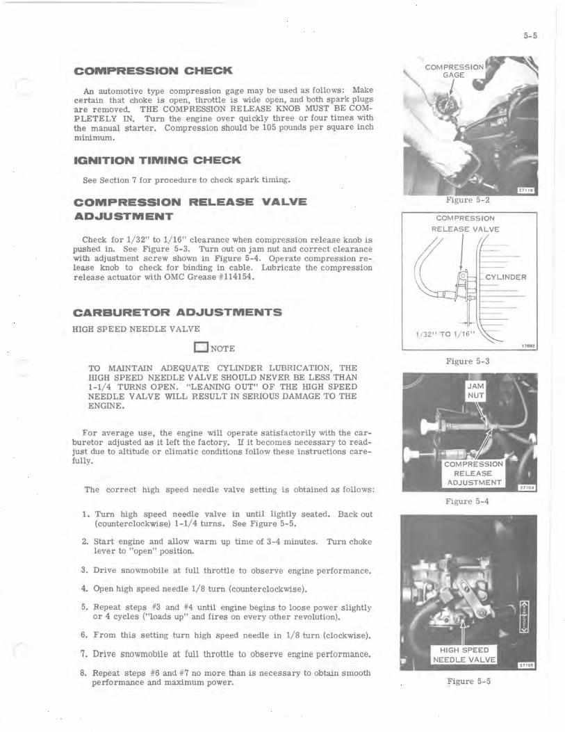
An automotive type compression gage may be used as follows: Make certain that choke is open, throttle is wide open, and both spark plugs are removed. THE COMPRESSION RELEASE KNOB MUST BE COMPLETELY IN. Turn the engine over quickly three or four times with the manual starter. Compression should be 105 pounds per square inch minimum.
IGNITION TIMING CHECK
See Section 7 for procedure to check spark timing.
COMPRESSION RELEASE VALVE AD,",USTMENT
Check for 1/32" to 1/16" clearance when compression release knob is pushed in. See Figure 5-3. Turn out on jam nut and correct clearance with adjustment screw shown in Figure 5-4. Operate compression release knob to check for binding in cable. Lubricate the compression release actuator with OMC Grease #114154.
CARBURETOR AD,",USTMENTS
HIGH SPEED NEEDLE VALVE
o NOTE
TO MAINTAIN ADEQUATE CYLINDER LUBRICATION, THE HIGH SPEED NEEDLE VALVE SHOULD NEVER BE LESS THAN 1-1/4 TURNS OPEN. "LEANING OUT" OF THE HIGH SPEED NEEDLE VALVE WILL RESULT IN SERIOUS DAMAGE TO THE ENGINE.
For average use, the engine will operate satisfactorily with the carburetor adjusted as it left the factory. If it becomes necessary to readjust due to altitude or climatic conditions follow these instructions carefully.
The correct high speed needle valve setting is obtained as follows:
1. Turn high speed needle valve in until lightly seated. Back out (counterclockwise) 1-1/4 turns. See Figure 5-5.
2. Start engine and allow warm up time of 3-4 minutes. Turn choke lever to "open" position.
3. Drive snowmobile at full throttle to observe engine performance.
4. Open high speed needle 1/8 turn (counterclockwise).
5. Repeat steps #3 and #4 until engine begins to loose power slightly or 4 cycles ("loads up" and fires on every other revolution).
6. From this setting turn high speed needle in 1/8 turn (clockwise).
7. Drive snowmobile at full throttle to observe engine performance.
8. Repeat steps #6 and #7 no more than is necessary to obtain smooth performance and maximum power.
COMPRESSION
RELEASE VALVE
1
5-5
CYLINDER
1708Z
Figure 5-3
Figure 5-4
Figure 5-5
5-6
Figure 5-6
L PULL COVER STRAIGHT OFF WITH SLIGHT TWIST
Figure 5-7
ONOTE THE HIGH SPEED NEEDLE VALVE SHOULD NEVER BE SET LEANER THAN 1-1/ 4 TURNS OPEN.
Two cycle engines are lubricated by oil that is drawn into the crankcase with the fuel charge. Although they will start and run with a leaner mixture, serious engine damage may result from too lean a setting.
A. TOO LEAN A SETTING if engine misses, backfires, and runs rough. Open high speed needle 1/8 turn more (counterclockwise). Repeat this test procedure until engine begins to 4-cycle (loads up). At this point turn high speed needle 1/8 turn in (clockwise) until smooth engine performance is obtained.
B. TOO RICH A SETTING if engine 4- cycles (loads up and fires on every other revolution). Condition noticed also by a loss of power. Turn high speed needle in 1/8 turn (clockwise) until smooth engine performance is obtained.
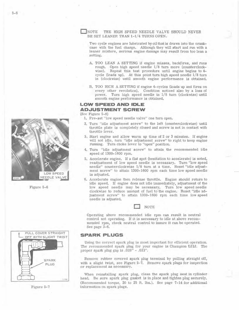
LOW SPEED AND IDLE ADJUSTMENT SCREW (See Figure 5-6)
1. Pre-set "low speed needle valve" one turn open.
2. Turn "idle adjustment screw" to the left (counterclockwise) until throttle plate is completely closed and screw is not in contact with throttle lever.
3. Start engine and allow warm up time of 2 or 3 minutes. If engine will not idle, turn "idle adjustment screw" to right to keep engine running. Turn choke lever to "open" position.
4. Turn "idle adjustment screw" to attain the recommended idle speed of 1300-1600 rpm.
5. Accelerate engine. If a flat spot (hesitation to accelerate) is noted, readjustment of low speed needle is necessary. Turn "low speed needle" counterclockwise 1/8 turn at a time. Reset "idle adjustment screw" to attain 1300-1600 rpm each time low speed needle is adjusted.
6. Accelerate engine then release throttle. Engine should return to idle speed. If engine does not idle immediately, adjustment of the low speed needle may be necessary. Turn low speed needle clockwise to reduce amount of fuel to the engine. Reset "idle adjustment screw" to attain 1300-1600 rpm each time low speed needle is adjusted.
o NOTE
. Operating above recommended idle rpm can result in neutral control not operating. If it is necessary to idle at above recommended rpm, check neutral control to insure it can be operated. See page 3-6.
SPARK PLUGS
USing the correct spark plug is most important for efficient operation. The recommended spark plug for your engine is Champion UJ2J. The proper spark plug gap is .028" - .033".
Remove rubber covered spark plug terminal by pulling straight off, with a slight twist, see Figure 5-7. Remove spark plugs for inspection or replacement as necessary.
When reinstalling spark plug, clean the spark plug seat in cylinder head. Be sure spark plug gasket is in place and tighten plug securely. (Recommended torque, 20 to 25 ft. lbs.). See page 7-14 for additional information on spark plugs.

a. Remove the idle speed mixture screw (14), washer and tension spring. Inspect for damaged threads (see Figure 6-7).
b. Remove the metering diaphragm cover (29), the metering diaphragm (28), and gasket (27). Inspect the cover for nicks, dents, or cracks that might hamper operation. Inspect the metering diaphragm; the center plate must be riveted securely to the diaphragm and the diaphragm should be free of holes and imperfections. The gasket should be replaced if there are holes or creases on its sealing surface. The parts must be reassembled in the correct order. The gasket should be assembled onto the carburetor body casting first, then the metering diaphragm is assembled next to the gasket.
c. Remove the hinge pin retaining screw (25), the hinge pin (23), inlet control lever (26) and the inlet tension spring (24). Use caution in removing these parts. Spring pressure may push the inlet control lever out of the casting. Inspect the parts for wear or damage. The inlet control lever must rotate freely on the hinge pin.
d. Handle the inlet spring carefully. Do not stretch this spring or change its compression characteristics. If in doubt about its condition, replace it.
e. Remove the inlet needle (22). Remove the inlet seat assembly using a 3/8-inch thin wall socket. Remove the inlet seat gasket.
f. The inlet seat assembly consists of a brass cage and a rubber insert for the inlet needle seat. Assemble the insert into the cage with the molded rim side away from the inlet needle point.
Some HD carburetors are equipped with a rubber tipped needle, a brass inlet seat and a copper gasket. The installation instructions below apply to both types of inlet seats.
The inlet needles and seats are matched and tested for leaks at the factory and the parts must be kept in matched sets. When installing the insert cage into the carburetor body, use a new gasket. Do not force the cage, as you may strip the threads or distort the insert. Use a torque wrench to apply 40 to 50 inch-pounds torque. The needle and seat assembly must be clean to insure correct performance.
g. Remove and inspect the points of the high speed and low speed (Figure 6-2) needle valves. Through misuse, either mixture screw pOint may be bent (extruded) from being - forced into the casting seat or possibly broken off in the casting (see Figure 6-3). - If either mixture screw is damaged, be sure to inspect the casting. If the adjustment seats are damaged, a new body casting is required. Check for clogged inlet and return line screen.
IMPORTANT
Do not alter return line elbow openings. This elbow controls inlet pressure and fuel flow to prevent vapor locking in carburetor and fuel pump.
h. Welch plugs seal the idle by-pass parts and main nozzle ball check valve from the metering chamber. Accumulated dirt can usually be blown out through the mixture screwholes. However, an unusually dirty carburetor requires the removal of these plugs. Drill just through the welch plug carefully with a 1/ 8" drill. Drilling too deeply may ruin the casting or the ball check valve. Use a small punch to remove the plug.
6-3
GOOD
WORN
17142
Figure 6-3
6- 4
TOO HIGH
DEPRESS HERE THEN PUSH TAB DOWN
TOO LOW DEPRESS HERE
PRY UP HERE CONTROL
LEVER
27097
17087
Figure 6-4
INLET CONT ROL LE VER
Figure 6- 5
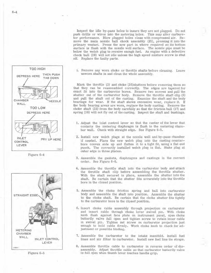
Inspect the idle by-pass holes to insure they are not plugged. Do not push drills or wires into the metering holes. This may alter carburetor performance. Blow plugged holes clean with compressed air. Remove the main nozzle ball check assembly (21), pressing it into the primary venturi. Press the new part in where required so its bottom surface is flush with the nozzle well surface. The nozzle pipe must be below the welch plug to receive enough fuel. An engine with a defective check ball (19) will not idle unless the high speed mixture screw is shut off. Replace the faulty parts.
i. Remove any worn choke or throttle shafts before cleaning. Leave unworn shafts in and clean the whole assembly.
Mark the throttle (3) and choke (16)shutters before removing them so that they can be reassembled correctly. The edges are tapered for exact fit into the carburetor bores. Remove two screws and pull the shutter out of the carburetor body. Remove the throttle shaft clip (5) and pull the shaft out of the casting. Examine the shaft and the body bearings for wear. If the shaft shows excessive wear, replace it. If the body bearing areas are worn, replace the body casting. Remove the choke shaft (33) from the body carefully so that the friction ball (17) and spring (18) will not fly out of the casting. Inspect the shaft and bushings.
1. Adjust the inlet control lever so that the center of the lever that contacts the metering diaphragm is flush to the metering chamber wall. Check with straight edge. See Figure 6-5.
2. Install new welch plugs at the nozzle well and by-pass chamber if needed. Place the new welch plug into the casting counterbore convex side up and flatten it to a tight fit, using a flat end punch. The correctly installed welch plug is flat. Stake plug at outer edge in three places.
3. Assemble the gaskets, diaphragms and castings in the correct order. See Figure 6-6.
4 . Assemble the throttle shaft into the carburetor body and attach the throttle shaft clip before assembling the throttle shutter. With the shaft secured in place, assemble the shutter into the shaft. Be certain that the shutter fits accurately into the throttle bore in the closed position.
5. Assemble the choke friction spring and ball into carburetor body and assemble the shaft into position. Assemble the shutter to the choke shaft. Be certain that the choke shutter fits tightly to the carburetor bore in the closed position.
6. Insert choke cable assembly through prOjection on carburetor and insert cable through choke lever swivel pin. With choke knob flush against face plate on instrument panel, open choke butterfly valve full open and tighten screw to retain inner cable in swivel pin. Tighten set screw on carburetor projection just enough to hold cable firmly. Work choke knob to check for adjustment or possible binding.
7. Assemble the carburetor to the intake manifold. Install fuel lines and air filter to carburetor. Install new fuel line tie straps.
8. Assemble throttle cable to carburetor in reverse order of disassembly. Adjust throttle cable so that carburetor butterfly valve is full open when thumb lever touches handle grip.
r
2
28
29
Figure 6-6
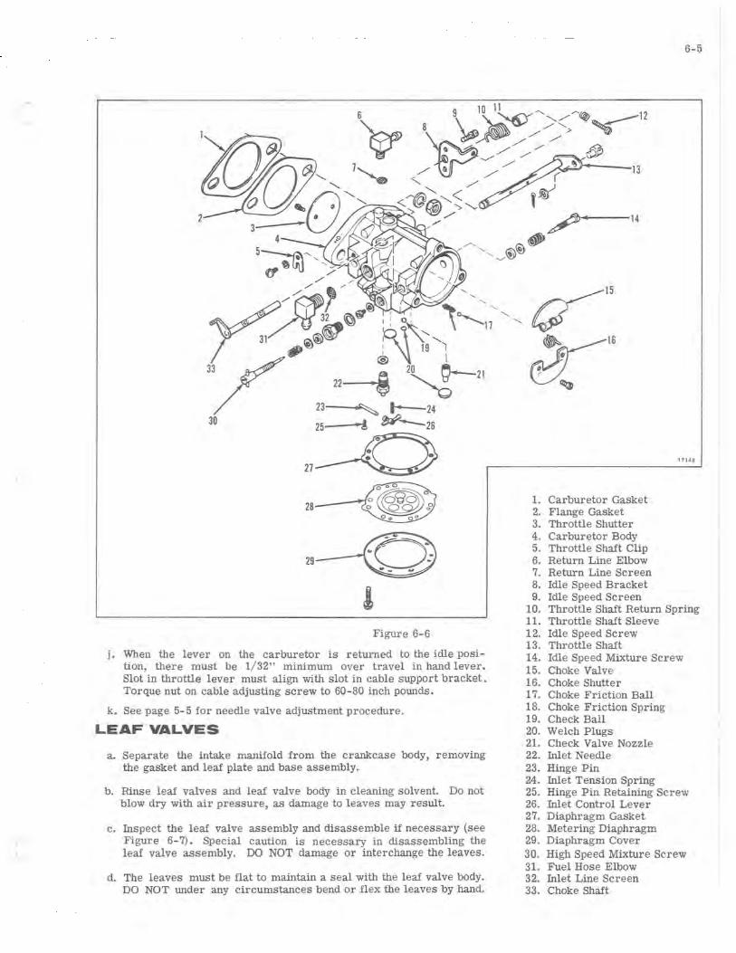
j. When the lever on the carburetor is returned to the idle position, there must be 1/ 32" minimum over travel in hand lever. Slot in throttle lever must align with slot in cable support bracket. Torque nut on cable adjusting screw to 60-80 inch pounds.
k. See page 5-5 for needle valve adjustment procedure.
LEAF VALVES
a. Separate the intake manifold from the crankcase body, removing the gasket and leaf plate and base assembly.
b. Rinse leaf valves and leaf valve body in cleaning solvent. Do not blow dry with air pressure, as damage to leaves may result.
c. Inspect the leaf valve assembly and disassemble if necessary (see Figure 6-7). SpeCial caution is necessary in disassembling the leaf valve assembly. DO NOT damage or interchange the leaves.
d. The leaves must be flat to maintain a seal with the leaf valve body. DO NOT under any circumstances bend or flex the leaves by hand.
6-5
17143
1. Carburetor Gasket 2. Flange Gasket 3. Throttle Shutter 4. Carburetor Body 5. Throttle Shaft Clip 6. Return Line Elbow 7. Return Line Screen 8. Idle Speed Bracket 9. Idle Speed Screen
10. Throttle Shaft Return Spring 11. Throttle Shaft Sleeve 12. Idle Speed Screw 13. Throttle Shaft 14. Idle Speed Mixture Screw 15. Choke Valve 16. Choke Shutter 17. Choke Friction Ball 18. Choke Friction Spring 19. Check Ball 20. Welch Plugs 21. Check Valve Nozzle 22. Inlet Needle 23. Hinge Pin 24. Inlet Tension Spring 25. Hinge Pin Retaining Screw 26. Inlet Control Lever 27. Diaphragm Gasket 28. Metering Diaphragm 29. Diaphragm Cover 30. High Speed Mixture Screw 31. Fuel Hose Elbow 32. Inlet Line Screen 33. Choke Shaft
6-6
HOLE FOR FUEL PUMP
PULSE ACTION
LEAF PLATE
INTAKE MANIFOLD
STOP GASKET LEAVES
BODY
LEAF PLATE AND BASE ASSEM. 17088
Figure 6-7
FUEL PUMP BODY
MOUNTING HOLES
Figure 6-8
FILTER FILTER
CAP
Figure 6-9
17089
17089
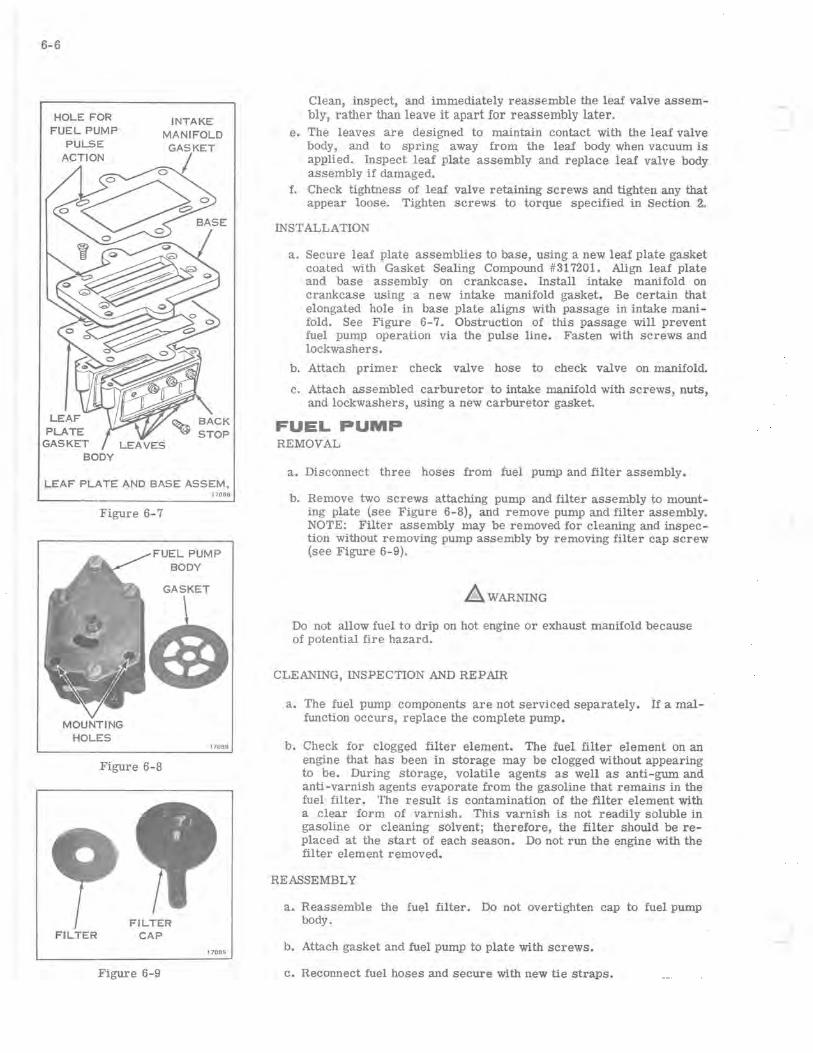
Clean, inspect, and immediately reassemble the leaf valve assembly, rather than leave it apart for reassembly later.
e. The leaves are designed to maintain contact with the leaf valve body, and to spring away from the leaf body when vacuum is applied. Inspect leaf plate assembly and replace leaf valve body assembly if damaged.
f. Check tightness of leaf valve retaining screws and tighten any that appear loose. Tighten screws to torque specified in Section 2.
INSTALLATION
a. Secure leaf plate assemblies to base, using a new leaf plate gasket coated with Gasket Sealing Compound #317201. Align leaf plate and base assembly on crankcase. Install intake manifold on crankcase using a new intake manifold gasket. Be certain that elongated hole in base plate aligns with passage in intake manifold. See Figure 6-7. Obstruction of this passage will prevent fuel pump operation via the pulse line. Fasten with screws and lockwashers.
b. Attach primer check valve hose to check valve on manifold.
c. Attach assembled carburetor to intake manifold with screws, nuts, and lockwashers, using a new carburetor gasket.
FUEL PUMP REMOVAL
a. Disconnect three hoses from fuel pump and filter assembly.
b. Remove two screws attaching pump and filter assembly to mounting plate (see Figure 6-8), and remove pump and filter assembly. NOTE: Filter assembly may be removed for cleaning and inspection without removing pump assembly by removing filter cap screw (see Figure 6-9).
LlWARNING
Do not allow fuel to drip on hot engine or exhaust manifold because of potential fire hazard.
CLEANING, INSPECTION AND REPAIR
a. The fuel pump components are not serviced separately. If a malfunction occurs, replace the complete pump.
b. Check for clogged filter element. The fuel filter element on an engine that has been in storage may be clogged without appearing to be. During storage, volatile agents as well as anti-gum and anti-varnish agents evaporate from the gaSOline that remains in the fuel filter. The result is contamination of the filter element with a clear form of varnish. This varnish is not readily soluble in gasoline or cleaning solvent; therefore, the filter should be replaced at the start of each season. Do not run the engine with the filter element removed.
REASSEMBLY
a. Reassemble the fuel filter. Do not overtighten cap to fuel pump body.
b. Attach gasket and fuel pump to plate with screws.
c. Reconnect fuel hoses and secure with new tie straps.
FUEL PRIMER a. The primer is a simple pump which pumps raw fuel from the fuel
line, thru check valves, directly into the intake manifold above the leaf valves (see Figure 6-1).
b. To check operation of the primer, disconnect hose from manifold check valve. A spurt of fuel should be evident when the plunger is depressed. If little or no fuel is discharged, check the valves in the fuel line, and fuel line fitting for leakage or sticking (refer to Figure 6-1).
c. Check valve above fuel primer "T" fitting must be in verticle position in order to operate.
AIR FILTER
The carburetor is equipped with an automotive type paper air filter element that should be cleaned once during the operating season, and replaced after a year's service. When pores in paper are plugged, engine will receive a rich fuel/air mixture and run rough and get poor fuel economy. To clean filter element, shake to dislodge dirt particles and blow with compressed air from inside, holding nozzle about two inches from filter. 00 NOT wash or oil filter element.
FUEL TANK a. For correct fuel and lubricant mixtures and break-in instructions,
see Section 12. b. The importance of using a fresh clean fuel mixture cannot be
overstressed. Gum will form in old fuel which will clog filter screens, fuel passages, carburetor orifices, leaf valves and check valves. Remove tank to empty old fuel. Reinstall it and begin with a fresh supply every season.
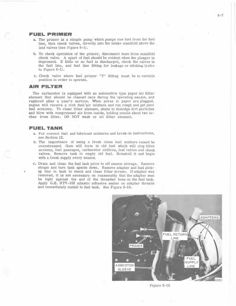
c. Drain and clean the fuel tank prior to off season storage. Remove straps and turn tank upside down. Remove adapter and fuel pick-
, up line in tank to check and clean filter screen. If adapter was removed, it is not necessary on reassembly that the adapter seat be tight against the end of the threaded boss on the fuel tank. Apply G.E. RTV -102 silastic adhesive sealer on adapter threads and immediately install to fuel tank. See Figure 6-10.
Figure 6-10
6-7
6-8
17263
Figure 6-11
d. Clean the tank with gaSOline poured through a filtering funnel. Cover the fuel line opening and agitate the tank. Empty it through the fill opening. Then reinstall the tank and hoses. See follOwing procedure to install new fuel line tie straps.
e. Check to see there are no leaks at fuel hose connections.
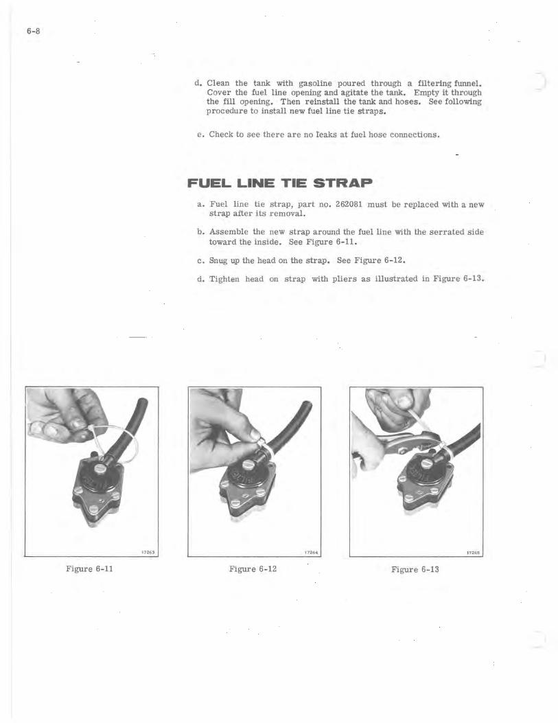
FUEL LINE TIE STRAP
a. Fuel line tie strap, part no. 262081 must be replaced with a new strap after its removal.
b. Assemble the new strap around the fuel line with the serrated side toward the inside. See Figure 6-11.
c. Snug up the head on the strap. See Figure 6-12.
d. Tighten head on strap with pliers as illustrated in Figure 6-13.
17264 172.65
Figure 6-12 Figure 6-13

(
7-1
SECTION "7
IGNITION AND ELECTRICAL SYSTEMS
TABLE OF CONTENTS
DESCRIPTION 7-2
TEST EQUIPMENT .................. . ..... . . . .•......•..•..... . 7-2
C.D. IGNITION SYSTEM TROUBLE SHOOTING . . . . . . • . • . . . . . . . . . . . . . . . . . . 7-3 INTRODUCTION . . . . . . . . . . . . . . . . . . . . . . . . . . . . . • . . . • . . . • . . . . . 7-3 DO'S AND DONT'S . . . • . . . . . • . . . . . . . . . . . . . . . . . • . • . • • . . . . . . • . . 7-3 TEST #1 IGNITION COILS OUTPUT CHECK ..............••......•. 7-4 TEST #2 IGNITION SWITCH CHECK. . . . . . . . . . . . . . . . . . . . . . . . . . . . . . 7-5 TEST #3 CHARGE COIL OUTPUT CHECK. . . . . . . . . . . . . . . . . . . . . . . . . . 7-6 TEST #4 RETARD SENSOR COIL INPUT CHECK ..................... 7-7 TEST # 5 POWER PACK I OUTPUT CHECK. . . . . . . . . . . . . . . . . . . . . . . . . 7-8 TEST #6 IGNITION SWITCH CONTINUITY GROUND CHECK. . . . . . . . . . . . . . 7-9 TEST #7 ADVANCE SENSOR COIL RESISTANCE CHECK. • . . . . . . . . . . . • . . 7-10 TEST #8 RETARD SENSOR COIL RESISTANCE CHECK. . . . . . . . • . . . . . . . . 7-10 TEST #9 CHARGE COIL RESISTANCE CHECK. . . . . . . . . . . . . . . . • . . . . . . 7-10 TEST #10 IGNITION COIL CONTINUITY. POWER AND INSULATION CHECKS. . 7-10 TEST #11 IGNITION TIMING CHECK .................••....•..•.. 7-11
CHARGE AND ALTERNATOR SYSTEM REPAIR. • . • • . . • • • . . . . . . • . . . • . . . . . 7-12 REMOVAL . . . . . . . • . . • • • . . . • • . . . . . . . . . . • . . • . . . • • . . . . . . . 7-12 REASSEMBLY .................•.•.......••....••...•..••. 7-13
IGNITION TIMING. . . . . . . . . • . . . . . . . . . . . . . . . . . . • . . . • . . . . . . . . . . . . . 7-14
SPARK PLUGS ......•............•..........•.•••.••••••••••. 7-14, 15
BATTERY ........................•.......•...........•...••. DESCRIPTION ...•.•.•.............•.•••••.....•••..•..... SPECIFICATIONS ..•...•..•...........•• . •.•...• ........... REMOVAL AND INSTALLATION .........•.•.•... ............... BATTERY SERVICING .............................•......... BATTERY CARE ......... . ........... , ....•......•.••...... BATTERY TESTING ...... .. .. .... ...... .......•. •...• ...•.. BATTERY CHARGING ...................................... . SLOW CHARGING ..•......•............•...•. , .........••.. WARRANTy ......•..•...••............••...•••.•.•.......
7-16 7-16 7-16 7-16 7-17 7-17 7-18 7-18 7-18 7-18
STARTER SYSTEM ... . . . . . . . • • • . • . . . • . . . . . . . • . . . . . . . • • . . . . . . . .. 7-19 DESCRIPTION ........•.....••.........•...•.••.••......•. 7-19 MAINTENANCE ... •.•.....•.....•......... .•..... ... .. •.•. 7-19 STARTER SYSTEM TESTING ........ . ... •••..... ........•..... 7-19
STARTER CIRCUIT TESTING. . . . . . . . . . . . . . • • • • • . • . • . . . . . • . 7-19 STARTER MOTOR TESTING. . . . . . . . • • • . • . • • . . . . . • . . . . . . • . . 7-20
INSPECTION OF STARTER MOTOR. . . . . . . • • • • • • • • • • • • • • • • • . . • . • . 7-21 BELT TENSION. . . . . . . • . • . • . . • . . . . • . . . . . . . . . . . . . • • • . . . . . • . • 7-22
ALTERNATOR . . . • • . . . . • • . . . . . . . . . . . . . . • • • • • • • • • • • • • • • • • • . . . . • 7-22 TROUBLE SHOOTING. . . • • . . • . • . . • • . . . • . . • . . • . • . . . • • • . • . • . • • • 7-22 ALTERNATOR COILS . •.. ...........•......•...........•..•. 7-23 TEST #1 ALTERNATOR COIL RESISTANCE TEST. . . . . . . . . . . . . . . . . . . . 7-23 TEST #2 ALTERNATOR COIL OUTPUT TEST. . . . . • . . . . . . . . . . . . . . . . . 7-23 CHECKING RECTIFIER DIODES ...........•...•.•.•............ 7-24 ALTERNATOR AND CHARGE COIL REPLACEMENT .................. 7-24 BLOCKING DIODE TEST ...................................... 7-24 SAFETY STOP-SWITCH TEST ................................. 7-24 DIMMER SWITCH TEST. . . . . . . . . . . . . . . . . . . . . . . . . . . . . . . . . . . . . . 7-24 BRAKE LAMP SWITCH TEST. . . . . . . . . . . . . . . . . . . . . . . . • . . . . . . . . . 7-24
WIRING DIAGRAMS. . . . . . . . . . . . . . . . . . . . . . . . . . . . . . . .. AT BACK OF MANUAL
7-2
GROUND 2. 7069
Figure 7-1
Figure 7-2
27070
Figure 7- 3
DESCRIPTION
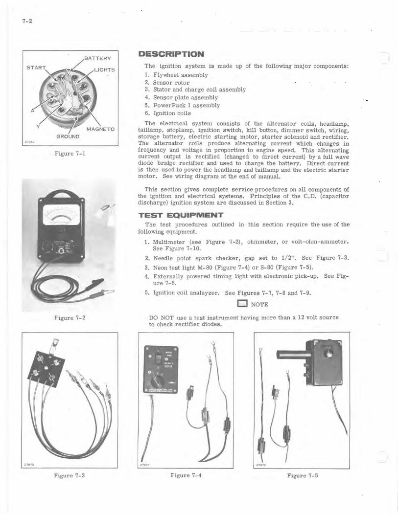
The ignition system is made up of the following major components:
1. Flywheel assembly 2. Sensor rotor 3. Stator and charge coil assembly 4. Sensor plate assembly 5. PowerPack 1 assembly 6. Ignition coils
The electrical system consists of the alternator cOils, headlamp, taillamp, stoplamp, ignition switch, kill button, dimmer switch, wiring, storage battery, electric starting motor, starter solenoid and rectifier. The alternator coils produce alternating current which changes in frequency and voltage in proportion to engine speed. This alternating current output is rectified (changed to direct current) by a full wave diode bridge rectifier and used to charge the battery. Direct current is then used to power the headlamp and taillamp and the electric starter motor. See wiring diagram at the end of manual.
This section gives complete service procedures on all components of the ignition and electrical systems. Principles of the C.D. (capacitor discharge) ignition system are discussed in Section 3.
TEST EQUIPMENT The test procedures outlined in this section require the use of the
following equipment.
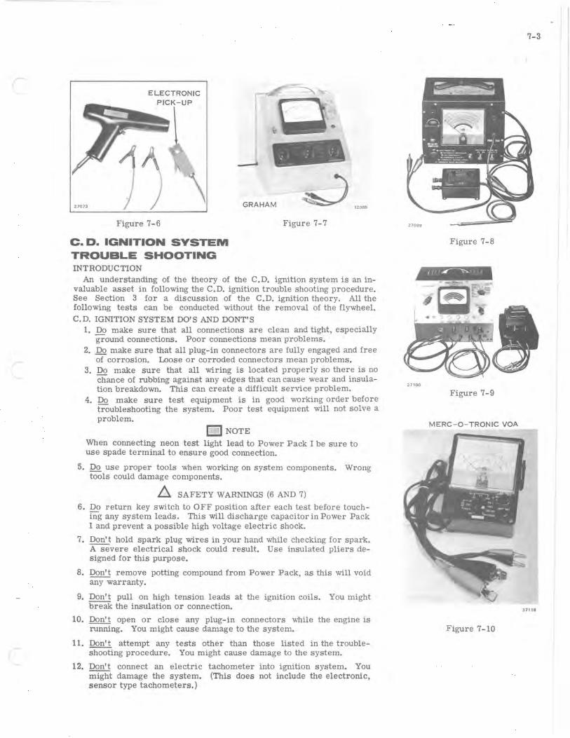
1. Multimeter (see Figure 7-2), ohmmeter, or volt-ohm-ammeter. See Figure 7-10.
2. Needle point spark checker, gap set to 1/2". See Figure 7-3.
3. Neon test light M-80 (Figure 7-4) or S-80 (Figure 7-5).
4. Externally powered timing light with electronic pick-up. See Figure 7-6.
5. Ignition coil analayzer. See Figures 7-7, 7-8 and 7-9.
D NOTE
DO NOT use a test instrument having more than a 12 volt source to check rectifier diodes.
27072.
Figure 7-4 Figure 7-5
ELECTRONIC
Figure 7-6
c. D. IGNITION SYSTEM TROUBLE SHOOTING INTRODUC TION
--\
GRAHAM 12985
Figure 7-7
An understanding of the theory of the C.D. ignition system is an invaluable asset in following the C.D. ignition trouble shooting procedure. See Section 3 for a discussion of the C.D. ignition theory. All the following tests can be conducted without the removal of the flywheel. C.D. IGNITION SYSTEM DO'S AND OONT'S
1. Do make sure that all connections are clean and tight , especially ground connections. Poor connections mean problems.
2. Do make sure that all plug-in connectors are fully engaged and free of corrosion. Loose or corroded connectors mean problems.
3. Do make sure that all wiring is located properly so there is no chance of rubbing against any edges that can cause wear and insulation breakdown. This can create a difficult service problem.
4. Do make sure test equipment is in good working order before troubleshooting the system. Poor test equipment will not solve a problem. o NOTE
When connecting neon test light lead to Power Pack I be sure to use spade terminal to ensure good connection.
5. Do use proper tools when working on system components. Wrong tools could damage components.
~ SAFETY WARNINGS (6 AND 7)
6. Do l'eturn key switch to OFF position after each test before touching any system leads. This will discharge capacitor in Power Pack I and prevent a possible high voltage electric shock.
7. Don't hold spark plug wires in your hand while checking for spark. A severe electrical shock could result. Use insulated pliers deSigned for this purpose.
8. Don't remove potting compound from Power Pack, as this will void any warranty.
9. Don't pull on high tension leads at the ignition coils. You might break the insulation or connection.
10. Don't open or close any plug-in connectors while the engine is running. You might cause damage to the system.
11. Don't attempt any tests other than those listed in the troubleshooting procedure. You might cause damage to the system.
12. Don't connect an electric tachometer into ignition system. You might damage the system. (This does not include the electrOnic, sensor type tachometers.)
7-3
Figure 7-8
III'~""
-~ ..
27100
Figure 7-9
MERC-O- TRONIC VOA
37 118
Figure 7-10
7-4
Z709Z
CHARGE COIL
NEEDLE POINT SPARK CHECKER
1/ 2" GAP
13. Don't connect this sytem to any voltage source other than what is specified. You might damage the system.
o NOTE
When connecting test equipment leads or reconnecting engine wiring leads to Power Pack I always refer to the diagram provided. You must hook leads in correct location or possible damage to system will result.
When removing Power Pack I cover plate, make sure you place it alongside Power Pack I in same direction it was removed . . This will assure correct terminal identification. Also, replace black (ground) wire and screw to Power Pack #1 after cover is moved before conducting follOwing tests.
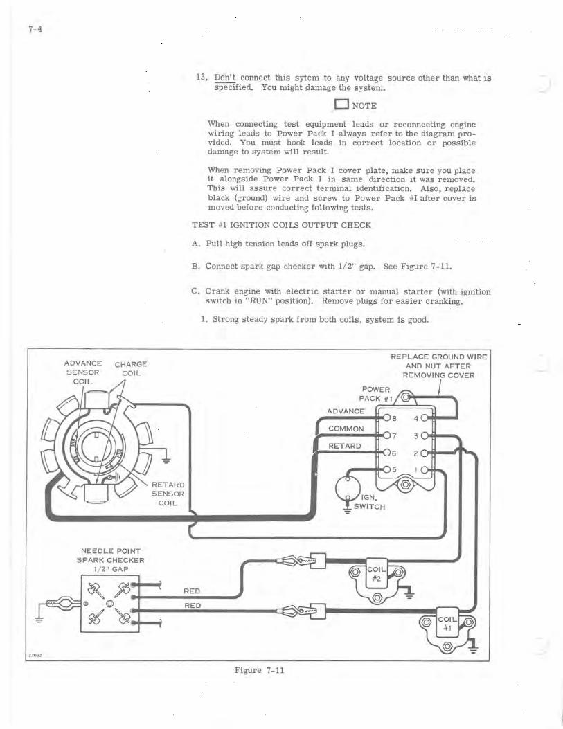
TEST #1 IGNITION COILS OUTPUT CHECK
A. Pull high tension leads off spark plugs.
B. Connect spark gap checker with 1/2" gap. See Figure 7-11.
C. Crank engine with electric starter or manual starter (with ignition switch in "RUN" position). Remove plugs for easier cranking.
1. Strong steady spark from both coils, system is good.
Figure 7-11
POWER
REPLACE GROUND WIRE AND NUT AFTER
REMOVING COVER
PACK #1 ((()If---......
ADVANCE
COMMON

-
2. Weak, erratic or no spark from one ignition coil, switch ignition coil leads on Power Pack I - repeat test. Spark on same cylinder still erratic, replace coil. Spark on opposite cylinder erratic, replace Power Pack I.
TEST #2 IGNITION SWITCH CHECK
A. Disconnect orange/black lead from Power Pack terminal #5. See Figure 7-11.
B. With ignition key in "RUN" position, check from orange/black lead to engine ground with ohmmeter set on Hi ohm scale. There should be no reading or infinite reading on meter indicating ignition switch not shorted and lead not grounded.
C. If less than 500k ohm reading, remove terminal connectors from ignition switch (see Figure 7-12) and remove ignition switch from dash panel. Turn ignition key to "RUN" position and take a resistance reading across the magneto and ground terminal of the ignition switch. See Figure 7-13.
D. If infinite reading indicated find problem in orange/black stripe lead.
E. If less than 500k ohm reading indicated, replace ignition switch.
F. Reconnect key switch lead to terminal #5 on Power Pack I.
Figure 7-12
OFF POSITION
GROUND
LIGHTS/RUN POSITION
Y
BATTERY
GROUND
27069
Figure 7-13
The magneto terminal and ground terminal are connected together.
The battery and lights terminals are connected together. The A and Y terminals are connected together.
RUN POSITION
o START POSITION
BATTERY
'TA"e) IGNITION SWITCH INTERNAL CONNECTORS
Figure 7-14
7-5
No ignition switch terminals are connected together.
The start and battery terminals are connected together.

7-6
2.7082
ADVANCE CHARGE SENSOR COIL
NEEDLE POINT SPARK CHECKER
1/ 2" GAP
TEST #3 CHARGE COIL OUTPUT CHECK
A. Remove charge coil brown/ white stripe lead from Power Pack terminal No.1.
B. Use Neon tester S80 or M80. Connect neon tester black lead to charge coil brown/white stripe lead and tester blue lead to engine ground. See Figure 7-15.
C. Set neon tester rotary switch to position #2. Depress load button "B."
D. Crank engine with electric starter or manual starter (with ignition switch in "RUN" position) and observe neon tester light.
1. If light is bright and steady, charge coils are good. Check Power Pack I output (Test #5).
2. If light is intermittent or no light, check for grounding or open leads to charge coils. Also check charge coils for correct resistance (Test #9).
E. Reconnect charge coil lead to terminal #1 on Power Pack #L
DEPRESS LOAD
BUTTON "B " POWER
PACK #1
ADVANCE
COMMON
REPLACE GROUND WIRE AND NUT AFTER
REMOVING COVER
~---....j~7 RETARD
BLACK
~ Qt, RED V"" r ....... __ ~ © RED
~~ .........
Figure 7-15

TEST #4 RETARD SENSOR COIL INPUT CHECK
A. Connect needle point spark checker as illustrated. See Figure 7-16.
B. Remove retard sensor white/ green stripe lead and advance sensor lead white/ black stripe from Power Pack terminals #6 and #8. (Do not allow leads to touch ground.) See Figure 7-16.
C. Connect neon tester S80 or M80 black lead to Power Pack terminal #6 and blue lead to sensor common (terminal #7). Set rotary switch to position #3. See Figure 7-16.
D. Crank engine with electric starter or manual starter (with ignition switch in "RUN" position) and at same time rapidly tap neon tester load button "B".
1. If there is spark across both gaps, check retard sensor leads and check sensor coil for correct resistance (Test #8).
2. If there is no spark on both coils, go to test #3. If there is no spark on one coil go to test #10.
E. Reconnect sensor leads #6 and #8 on Power Pack I.
ADVANCE CHARGE REPLACE GROUt'lD
2.7095
COIL
NEEDLE POINT SPARK CHECKER
1/ 2" GAP
~ j5~ ____ R_E_D __ ~ © RED
%~ ..........
WIRE AND NUT AFTER REMOVING COVER
TAP LOAD BUTTON ADVANCE
"BTl @ ( COMMON
BLUE RETARD@
BLACK I 0
Figure 7-16
7- 7
7 3
7-8
':'"
Z7085
ADVANCE CHARGE SENSOR COIL
NEEDLE POINT SPARK CHECKER
1/ 2" GAP
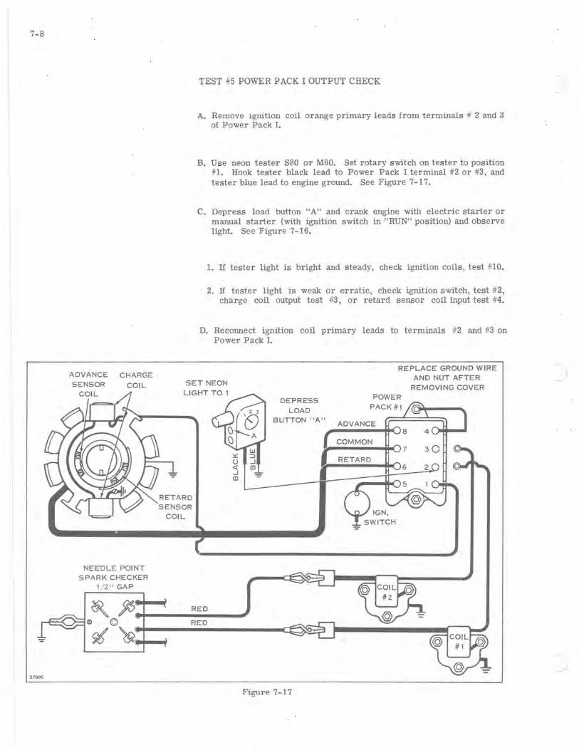
TEST #5 POWER PACK I OUTPUT CHECK
A. Remove ignition coil orange primary leads from terminals # 2 and 3 of Power Pack 1.
B. Use neon tester S80 or M80. Set rotary switch on tester to position #1. Hook tester black lead to Power Pack I terminal #2 or #3, and tester blue lead to engine ground. See Figure 7-17.
c. Depress load button "A" and crank engine with electric starter or manual starter (with ignition switch in "RUN" position) and observe light. See Figure 7-16.
1. If tester light is bright and steady, check ignition coils, test #10.
2. If tester light is weak or erratic, check ignition switch, test #2, charge coil output test #3, or retard sensor coil input test #4.
D. Reconnect ignition coil primary leads to terminals #2 and #3 on Power Pack 1.
SET NEON
DEPRESS LOAD
BUTTON "A"
REPLACE GROUND WIRE AND NUT AFTER
REMOVING COVER POWER
PACK#l
ADVANCE
COMMON
RETARD
':'"
~ ~ RED ~ © ~---------R-E-D------'
~~.~
Figure 7-17
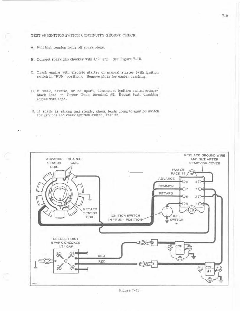
( TEST #6 IGNITION SWITCH CONTINUITY GROUND CHECK
A. Pull high tension leads off spark plugs.
B. Connect spark gap checker with 1/2" gap. See Figure 7-18.
C. Crank engine with electric starter or manual starter (with ignition switch in "RUN" position). Remove plu9s for easier cranking.
D. If weak, erratic, or no spark, disconnect ignition switch orange/ black lead on Power Pack terminal #5. Repeat test, cranking engine with rope.
E. If spark is strong and steady, check leads going to ignition switch for grounds and check ignition switch, Test #2.
ADVANCE CHARGE SENSOR COIL
7-9
REPLACE GROUND WIRE AND NUT AFTER
REMOVING COVER
POWER PACK #1
ADVANCE rr=~======~
COMMON
=
27092
NEEDLE POINT SPARK CHECKER
1/2" GAP
IGNITION SWITCH IN "RUNIT POSITION
~ ~~ ____ R_E_D __ -,
© RED
%~ .........
Figure 7-18
~----*,<:J7 3 ~~--.. RETARD

7-10
Figure 7-19
Figure 7-20
Figure 7-21
TEST #7 ADVANCE SENSOR COIL RESISTANCE CHECK
An engine that will start and idle, but dies out when accelerating, and with timing light connected will show the red fin (retard timing mark) and not the yellow fin (advance timing mark) when running has a bad advance sensor or Power Pack I. If previous tests on the Power Pack I were positive, a resistance check of the advance sensor coil should be made.
A. Remove the white/black stripe lead from terminal #8 of the Power Pack I, the black/white stripe lead from terminal #7, and the white/ green stripe lead from terminal #6. Check for 14 to 16 ohms resistance between leads #7 and #8. See Figure 7-19. If sensor coil resistance does not come within these tolerances, it must be replaced.
B. Coil or leads must not be shorted to ground. On ohmmeter hi ohms scale, check for a reading of infinity from either coil lead to ground. If there is a leakage to ground, check coil and leads and insulate area of leakage with tape.
TEST #8 RETARD SENSOR COIL RESISTANCE CHECK
An engine that is hard starting, kicks back, and with timing light connected will show yellow fin when cranking, has a defective retard sensor coil or Power Pack. If previous tests on the Power Pack were positive, a resistance check of the sensor coil should be made.
A. Remove the white/black stripe lead from terminal #8, the black/white stripe lead from terminal #7 and the White/green stripe lead from terminal #6. Check for 27 to 29 ohms resistance between leads #6 and #7. See Figure 7-20. If retard coil resistance does not come within these tolerances, it must be replaced.
B. Retard coil or lead must not be shorted to ground. On ohmmeter hi ohms scale, check for a reading of infinity from either coil lead to ground. If there is a leakage to ground, check retard coil and leads and inSUlate area of leakage with tape.
TEST # 9 CHARGE COIL RESISTANCE CHECK
A. Remove the brown/White stripe lead from Power Pack I terminal #1. Check for a total resistance of the two charge coils from lead to ground of 860 ± 10 ohms. See Figure 7-21. If resistance of the charge coils does not come within these tolerances, they must be replaced.
TEST # 10 IGNITION COIL CONTINUITY, POWER AND INSULATION CHECKS
To determine accurately the condition of the ignition coil, an ignition analyzer should be used. Without the use of test eqUipment, coils may be replaced needlessly. A wide variety of ignition analyzers are available from various manufacturers. The use of the Graham, MercO-Tronic, or Stevens ignition analyzers, and their adapter for C.D. ignition are particularly recommended. See Figures 7-7, 7-8 and 7-9.
Detailed instructions for the use of any tester are provided with the unit; therefore, only general information is given here. All components of the ignition system should be checked, even though replacing a single part seems to have corrected the trouble.

r The following values are provided for checking the ignition coil 581038.
Graham Tester Model 51
Maximum Secondary 1900 ± 190 Coil Index 60 Minimum Coil Test 9 Gap Index 50
Merc- O- Tronic Operating Amperage 1.4 Secondary Continuity 22 to 26 (index number)
Stevens Tester Model MA 75 Switch B Index Reading 20
~ SAFETY WARNING
Perform all tests on a wooden or insulated bench top to prevent leakage or shock hazards. Follow the equipment manufacturer's instructions. A low reading on the tester indicates a weak coil which must be replaced. No attempt should be made to improve this spark by increasing primary current; a coil is defective if it cannot be made to give a good reading on the specified primary current.
[:J NOTE
Zero meter before performing the continuity test.
A. CONTINUITY TEST (using MERC-O-TRONIC TESTER) Remove ignition coils. Connect meter leads to coil primary and secondary leads and turn meter selector switch to "Coil Continuity." See Figure 7 - 22. Index reading should be between 22 and 26.
B. Connect meter leads to adapter, adapter red lead to coil ground lead and adapter black lead to coil primary. See Figure 7-23. Connect coil high tension lead to meter output lead. Turn meter selector to "Coil Power Test" and apply power to coil. Secondary voltage should produce a steady spark at meter spark gap at 1.4 amps (black figures on number 1 scale). Check insulation by probing the coil and entire secondary lead with the grounded test probe. See Figure 7-24. Arcing will be apparent wherever the insulation has broken down, due to mOisture or carbon trails.
TEST #11 IGNITION TIMING CHECK
RET ARD TIMING CHECK
Connect test light to battery. Remove spark plugs to release compression for easier manual turning of engine. Clamp the test light electronic piCkup on a spark plug wire. (Arrow on pick-up must point toward plug.) Connect spark checker to high tension leads and ground to engine. Turn ignition switch to "RUN" position. It will be required that one person pull the starter rope vigorously, and a second person aim the test light at the timing slot and check the retard (red) fin on the flywheel which should be visible at cranking speed in the timing slot. See Figures 7-26 and 7- 27.
l7104
SECONDARY LEAD
Figure 7-22
ADAPTER
Figure 7-23
METER
ADAPTER LEADS
7-11
METER OUTPUT
COIL SECONDARY 27106
Figure 7-24

7-12
Figure 7-25
YELLOW FIN
RED '\.
FIN~
~~
17144 FLYWHEEL
KEYWAY
Figure 7-27
4TH FIN
(
1~IJ~j -~ ~',."",. . \, lit' , ~ """.y" .•. >.'
~
Figure 7-28
Figure 7-26
ADVANCE TIMING CHECK
Connect timing light to battery. Clamp timing light electronic pickup to one high tension lead. Run engine at idle speed (1300-1600 RPM) and aim timing light at timing slot. The advance (yellow) fin should be visible in the timing slot. See Figures 7-26 and 7-27.
CHARGE AND ALTERNATOR
SYSTEM REPAIR
REMOVAL
a. Remove starter assembly outer fan housing, breather from carburetor, cover from top of ignition coils, engine cover and bracket and power pack cover.
b. Remove three screws attaching ratchet and ratchet mount to flywheel (see Figure 7-29). Remove ratchet mount.
c. Remove flywheel nut (see Figure 7-30). Use spark plug wrench handle in hole on rim of flywheel to keep flywheel from turning while removing nut.
d. Remove belt on electric start models.
e. Remove flywheel from crankshaft (see Figure 7-31), using flywheel puller (Special Tool #378103). Charge coils, alternator coils and sensor coils are now accessible for servicing (see Figure 7-32).
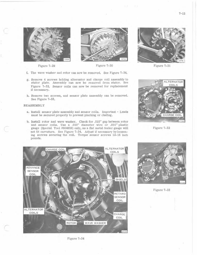
r
Figure 7-29 Figure 7-30
f. The wave washer and rotor can now be removed. See Figure 7-34.
g. Remove 4 screws holding alternator and charge coil assembly to stator plate. Assembly can now be removed from stator. See Figure 7-32. Sensor coils can now be removed for replacement if necessary.
h. Remove two screws, and sensor plate assembly can be removed. See Figure 7-33.
REASSEMBLY
a. Install sensor plate assembly and sensor coils. Important - Leads must be secured properly to prevent pinching or chafing.
b. Install rotor and wave washer. Check for .010" gap between rotor and sensor coils. Use a .010" diameter wire or .010" plastic gauge (Special Tool #604659) only, as a flat metal feeler gauge will not fit curvature. See Figure 7-34. Adjust if necessary by loosening screws securing the coil. Torque sensor screws 12-16 inch pounds.
Figure 7-34
7-13
Figure 7-31
Figure 7-32
Figure 7-33
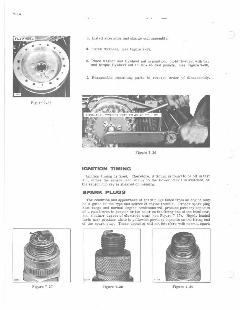
7-14
Figure 7-35
Z9156
Figure 7-37
c. Install alternator and charge coil assembly.
d. Install flywheel. See Figure 7-35.
e. Place washer and flywheel nut in position. Hold flywheel with bar and torque flywheel nut to 40 - 45 foot pounds. See Figure 7-36.
f. Reassemble remaining parts in reverse order of disassembly.
Figure 7-36
IGNITION TIMING
Ignition timing is fixed. Therefore, if timing is found to be off in test #11, either the sensor lead wiring to the Power Pack I is switched, or the sensor hub key is sheared or missing.
SPARK PLUGS
The condition and appearance of spark plugs taken from an engine may be a guide to the type and source of engine trouble. Proper spark plug heat range and normal engine conditions will produce powdery deposits of a rust brown to grayish or tan color on the firing end of the insulator, and a minor degree of electrode wear (see Figure 7-37). Highly leaded fuels may produce white to yellowish powdery deposits On the firing end of the spark plug. These deposits will not interfere with normal spark
17 150
Figure 7-38 Figure 7-39

(
;-
(~
plug performance if plugs are cleaned at regular service intervals. See page 4-3 for a discussion on spark plug heat range.
a. If the insulator tip is an exceptionally light tan or whitish color, or the center electrode burned away, the heat range may be too hot (see Figure 7-38).
b. A dark, black or sootish coloration, or wet appearance, ordinarily indicates the heat range as being too cold (see Figure 7-39). Black, sooty deposits on the entire firing end of the spark plug result from incomplete combustion due to an overly rich air-fuel mixture, incorrect choke setting, or misfiring caused by faulty ignition components.
c. A definite white coloration may indicate the presence of moisture in the combustion chamber. Similar deposits are caused by preignition.
d. Oil fouling deposits wet, sludgy deposits and is a result of misfiring or of excessive oil in the fuel mixture (see Figure 7-40).
e. Burned or overheated spark plugs may be identified by a white, burned, or blistered insulator nose, and badly eroded electrodes. Excessive deposits in the combustion chamber, a lean fuel mixture or improperly installed spark plugs can cause overheating.
The condition of spark plugs may provide an indication of other conditions requiring attention. Inspect each plug and gasket as it is removed. Place the spark plugs in a holder in order of removal, to assist in locating trouble. Inspect each plug for worn electrodes, glazed, broken, or blistered porcelain, and replace plugs where necessary. Plugs that are severely carbon fouled, that have blistered or cracked insulator tips, or plugs that have eroded electrodes must always be replaced. Plugs that are Slightly contaminated with deposits, or which have wider than recommended gap settings can be cleaned and regapped for further use. Plugs that appear slightly contaminated can be cleaned by careful scraping, using a small knife or Similar instrument. After combustion deposits have been removed, bend the side electrode back slightly so that the center electrode can be filed flat.
00 NOT clean plugs on abrasive blasting machines. This type of cleaning tends to remove the hard, smooth finish from the insulator tip and reduces the tip's resistance to the formation of combustion deposits. Blasting also tends to pack the abrasive between the insulator top and the metal shell of the plug. If the abrasive is not removed before in,stalling the plug, it may pass through the engine, causing piston or cylinder wall scoring.
After the plug has been cleaned, adjust the gap to .028 to .033 inch by bending the side electrode. Adjust only the Side electrode, as attempting to bend the center electrode will crack the insulator. Use a round wire feeler gage to measure gap adjustment (see Figure 7-41).
Poor engine performance and premature spark plug failure may result from improper spark plug installation. Before installing the plug, be sure the plug seat in the cylinder head is cleaned and free from obstructions. Clean and inspect spark plug hole threads. Always use new gaskets when installing spark plugs. Tighten spark plugs to 20 -25 foot pounds, using a torque wrench.
Improper installation is one of the greatest single causes of unsatisfactory spark plug performance. Improper installation is the result of one or more of the following:
1. Installation of plugs with insufficient torque to correctly compress the gasket.
7-15
Figure 7-40
17146
Figure 7-41
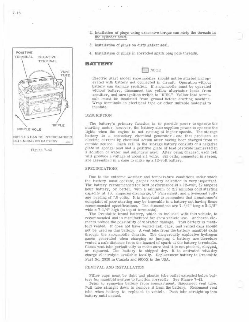
7-16
POSITIVE
TERMINAL NEGATIVE TERMINAL
NIPPLES CAN BE INTERCHANGED DEPENDING ON BATTERY 37 181
Figure 7-42
2. Istallation of plugs using excessive torque can strip the threads in the cylinder head.
3. Installation of plugs on dirty gasket seal.
4. Installation of plugs in corroded spark plug hole threads.
BATTERY o NOTE
Electric start model snowmobiles should not be started and operated with battery not connected in circuit. Operation without battery can damage rectifier. If snowmobile must be operated without battery, disconnect two yellow alternator leads from rectifier, and turn ignition switch to "RUN." Yellow lead terminals must be insulated from grolUld before starting machine. Wrap terminals in electrical tape or other suitable material to insulate.
DESCRIPTION
The battery's primary flUlction is to provide power to operate the starting motor; however, the battery also supplies power to operate the lights when the engine is not running at higher speeds. The storage battery is a secondary chemical generator - one that produces an electric current by chemical action after having been charged from an outside source. Each cell in the storage battery consists of a negative plate of sponge lead and a positive plate of lead peroxide immersed in a solution of water and sulphuric acid. After being charged, each cell will produce a voltage of about 2.1 volts. Six cells, connected in series, are assembled in a case to make up a 12-volt battery.
SPECIFICATIONS
Due to the extreme weather and temperature conditions lUlder which the battery must operate, proper battery selection is very important. The battery recommended for best performance is a 12-volt, 32 ampere hour battery, or better, with a minimum of 2.2 minutes cold starting capacity at 150 amperes discharge, 0° Fahrenheit, and a 5-second voltage reading of 7.8 volts. It is important to remember that a customer's complaint of poor starting may be traceable to a battery not having these recommended speCifications. The dimensions are 7-3/ 4" long x 5-1/8" wide x 7- 1/ 4" high (to top of terminals).
The Prestolite brand battery, which is included with this vehicle, is recommended and is manufactured for snow vehicle use. Anchored elements reduce the possibility of vibration damage. This battery is manifold vented. It does not have vented cell caps, and vented caps should not be used on this battery. A vent tube from the battery manifold exits through the snowmobile chassis. The dangerously explosive hydrogen gases generated when charging or jumping a battery are therefore vented a safe distance from the hazard of spark at the battery terminals. Check vent tube periodically to make sure that it is not pinched, clogged, or ruptured. The battery is shipped dry. It is activated with dry charge electrolyte available locally. Replacement battery is Prestolite Part No. 2920 in Canada and 9955X in the USA.
REMOVAL AND INSTALLATION
Filler caps must be tight and plastic tube outlet extended below battery for manifold system to flUlction correctly. See Figure 7-42.
Prior to removing battery from compartment, disconnect vent tube. Pull tube straight down to remove it from the battery. Recormect vent tube when battery is replaced in vehicle. Push tube straight up into battery lUltil seated.
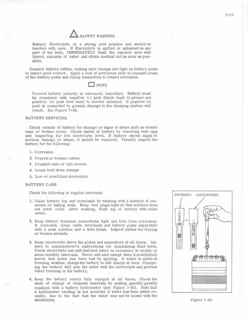
~ SAFETY WARNING
Battery Electrolyte is a strong acid solution and should be handled with care. If Electrolyte is spilled or splashed on any part of the body, IMMEDIATELY flush the exposed area with liberal amounts of water and obtain medical aid as soon as possible.
Connect battery cables, making sure clamps are tight on battery posts to insure good contact. Apply a coat of petroleum jelly to exposed areas of the battery posts and clamp connectors to retard corrosion.
DNOTE
Correct battery polarity is extremely important. Battery must be connected with negative (-) post (black lead) to ground and positive (+) post (red lead) to starter solenoid. If positive (+) post is connected to ground, damage to the charging system will result. See Figure 7-42.
BATTERY SERVICING
Check outside of battery for damage or signs of abuse such as broken case or broken cover. Check inside of battery by removing vent caps and insp"ecting for low electrolyte level. If battery shows signs of serious damage or abuse, it should be replaced. Visually inspect the battery for the following:
1. Corrosion
2. Frayed or broken cables
3. Cracked case or cell covers
4. Loose hold down clamps
5. Low or overfilled electrolyte
BATTERY CARE
Check the follOwing at regular intervals:
1. Clean battery top and terminals by washing with a solution of ammonia or baking soda. Keep vent plugs tight so that solution does not enter cells. After washing, flush top of battery with clean water.
2. Keep battery terminal connections tight and free from corrosion. If corroded, clean cable terminals and battery posts separately with a soda solution and a wire brush. Inspect cables for fraying or broken strands.
3. Keep electrolyte above the plates and separators at all times. Adhere to manufacturer's instructions for maintaining fluid level. Check electrolyte and add distilled water as necessary at weekly or semi-monthly intervals. Never add acid except when it is definitely known that some has been lost by spilling. If water is added in freezing weather, charge the battery to full charge at once. Chargeing the battery will mix the water with the electrolyte and prevent water freezing in the battery.
4. Keep the battery nearly fully charged at all times. Check the state of charge at frequent intervals by making speCific gravity readings with a battery hydrometer (see Figure 7-43). Note that a hydrometer reading is not accurate if water has been added recently, due to the fact that the water may not be mixed with the electrolyte.
7-17
CHARGED DISCHARGED
I
Figure 7-43
7-18
Self-discharge will cause storage batteries to become discharged and sulphated if they are not properly maintained in storage. To minimize self-diSCharge, store batteries in as cool a place as possible, so long as the electrolyte does not freeze. A battery which has been allowed to stand idle for a long period of time may be so badly damaged by sulphation that it can never be restored to a normal charge condition. Batteries should be recharged every 30 days to prevent this damage. Disconnect one of the battery leads before charging battery. If storage temperature is hot, more frequent charging will be necessary. Add water if necessary before charging, to bring electrolyte to proper level. Fully charged batteries have been known to withstand temperatures as low as _90 0 F.; a discharged battery will freeze at about _19 0 F., perhaps causing bursting of both the cell and battery cases.
BATTERY TESTING
a. Make sure battery is fully charged as described under SLOW CHARGING. Hydrometer readings taken on partially charged batteries are unreliable for the follOwing test.
b. Measure speCific gravity of electrolyte in each cell and compare readings with the follOwing; if cell readings are between 1.250 and 1.290, the battery is ready for use. Any variation in the speCific gravity between cells within this range does not indicate a defective battery. Readings should be corrected to 80° Fahrenheit for comparison. If this specifiC gravity of any cell falls outside this range (1.250 to 1.290), replace the battery.
BATTERY CHARGING
~SAFETY WARNING
Gases given off by a battery being charged or jumped are highly explosive. Keep battery in a ventilated area and away from cigarettes and open flames when charging or jumping. Turn off battery charger before removing cables from battery. Remove cables from good battery first, when jumping.
For best performance a good battery should be fully charged before being returned to service. DO NOT recharge the battery by the fast charge method. This method does not restore the full charge and also shortens the life of the battery.
o NOTE
DISCONNECT one of the battery leads before attaching battery charger to battery.
SLOW CHARGING
Battery is kept charged by alternator coils located beneath flywheel. It may be necessary to use a separate 12 volt battery charger occasionally to keep battery fully charged during long storage periods, or in extreme cold weather if engine is started repeatedly. Battery should be removed from compartment for charging and initial filling. Prior to removing battery from compartment, disconnect vent tube. Pull tube straight down to remove it from the battery. Reconnect vent tube when battery is replaced in vehicle. Push tube straight up into battery until it is seated. Adjust electrolyte to proper level by adding water, then charge battery at a maximum rate of 4 amperes until fully charged. Leave caps on battery while charging. Battery is fully charged when hydrometer scale shows a corrected reading of 1. 260 and does not change after three hourly readings. Cells will gas freely when fully charged.
PRESTOLITE BATTERY WARRANTY
Warranty on Prestolite batteries used in this snowmobile is covered directly by Prestolite, through their authorized battery service stations, for a period of 18 months in the United States and 9 months in Canada. Should a battery fail, due to inherent defects, during the first three (3)

( months of service, it will be replaced on a no-charge basis. Batteries that fail during the balance of the warranty period (15 months) in the U.S. and (6 months) in Canada will be replaced on a prorata basis.
In Canada Prestolite warranty should be handled through the dealer from whom the snowmobile was purchased or through a Prestolite battery depot.
The warranty period starts on the date the snowmobile is delivered to the original owner.
Should a battery fail, due to inherent defects, during the first three (3) months of service, it will be replaced on a no-charge basis. Batteries that fail during the balance of the warranty period (15 months) will be replaced on a pro rata basis.
STARTER SYSTEM DESCRIPTION
The electric starter system consists of the starter motor, starter SOlenoid, and the necessary cables and wires with their connectors. The starter motor converts electrical energy from the battery into mechanical power which is transmitted to the engine through the starter belt. The starter switch controls the operation by activating the starter solenoid which makes and breaks the high current circuit between the battery and the starter motor.
The starter solenoid (see Figure 7-44) closes the circuit through a movable contact disc which strikes two terminal contacts that are connected to the starter motor circuit. The solenoid winding, when energized, exerts a magnetic pull on the solenOid plunger, causing it to move the contact disc against the terminal contacts.
The starter motor sheave is disengaged when at rest and when engine is running. The rotation of the starter motor drives the pin on the motor shaft against the cam on the movable half of the sheave, forCing it to move in a lateral direction toward the fixed half of the sheave, engaging the starter belt. When the engine starts, the sheave is driven faster than the motor and sheave halves separate to the disengaged position. See Figure 7-45.
D NOTE Starter belt tension must be set with sufficient slack to prevent the engine from driving the starter motor. (See "BELT TENSION.")
MAINTENANCE The only starter motor maintenance required is periodic cleaning of
the outside of the starter motor and drive and a check of the starter belt tension. No periodic lubrication of the starter motor or solenoid is required. Starter motor need be removed for reconditioning only every 1000 hours or if the following tests indicate that the starter is not operating properly. If the starter motor does not crank the engine or if it cranks too slowly, cheCk the battery, cables, and connections. Inspect all wiring connections in the starter circuit to insure that they are clean and tight. Proceed with the following tests if additional troubleshooting is necessary.
STARTER SYSTEM TESTING The following tests fall into two groups, starter circuit tests and
starter motor tests. Starter circuit testing is a quick means of pinpOinting causes of hard starting which may result from a faulty electrical component in the starter circuit, and can be performed without remOving any components from the engine. NOTE: All starter circuit testing must be done with a fully charged, 12-volt battery.
STARTER CIRCUIT TESTING Starter Motor Amperage Draw Test
a. Ground spark plug high tension leads so that engine can be cranked without firing. Place clamp-on DC ammeter capable of reading at least 200 amperes around starter motor lead (see Figure 7-46).
PLUNGER
MOTOR TERMINAL.
7-19
WINDINGS
CONTACT DISC
SOLENOID
Figure 7-44
~ --MOVABLE HA~
OF PULLEY
TENSION ADJUSTMENT .. rr~.~ .....
Figure 7-45
I· STARTER MOTOR
~r;-,
Oll BATTERY ~
Figure 7-46
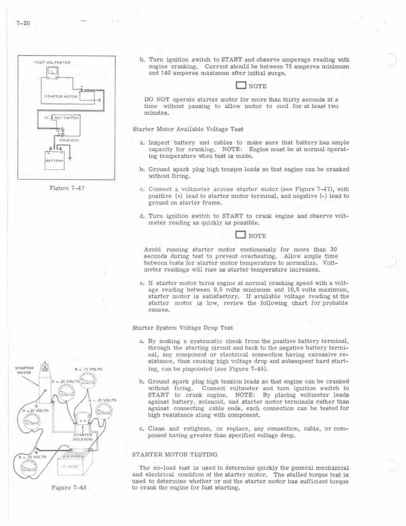
7-20
TEST VOLTMETER
Figure 7-47
Figure 7-48
b. Turn ignition switch to START and observe amperage reading with engine cranking. Current should be between 75 amperes minimum and 140 amperes maximum after initial surge.
DNOTE
DO NOT operate starter motor for more than thirty seconds at a time without pausing to allow motor to cool for at least two minutes.
Starter Motor Available Voltage Test
a. Inspect battery and cables to make sure that battery has ample capacity for cranking. NOTE: Engine must be at normal operating temperature when test is made.
b. Ground spark plug high tens~on leads so that engine can be cranked without firing.
c. Connect a voltmeter across starter motor (see Figure 7-47), with positive (+) lead to starter motor terminal, and negative (-) lead to ground on starter frame.
d. Turn ignition switch to START to crank engine and observe voltmeter reading as quickly as possible.
DNOTE
Avoid running starter motor continuously for more than 30 seconds during test to prevent overheating. Allow ample time between tests for starter motor temperature to normalize. Voltmeter readings will rise as starter temperature increases.
e. If starter motor turns engine at normal cranking speed with a voltage reading between 9.5 volts minimum and 10.5 volts maximum, starter motor is satisfactory. If available voltage reading at the starter motor is low, review the follOwing chart for probable causes.
Starter System Voltage Drop Test
a. By making a systematic check from the positive battery terminal, through the starting circuit and back to the negative battery terminal, any component or electrical connection having excessive reSistance, thus causing high voltage drop and subsequent hard starting, can be pinpointed (see Figure 7-48).
b. Ground spark plug high tension leads so that engine can be cranked without firing. Connect voltmeter and turn ignition switch to START to crank engine. NOTE: By placing voltmeter leads against battery, solenoid, and starter motor terminals rather than against connecting cable ends, each connection can be tested for high resistance along with component.
c. Clean and retighten, or replace, any connection, cable, or component having greater than specified voltage drop.
ST ARTER MOTOR TESTING
The no-load test is used to determine quickly the general mechanical and electrical condition of the starter motor. The stalled torque test is used to determine whether or not the starter motor has sufficient torque to crank the engine for fast starting.
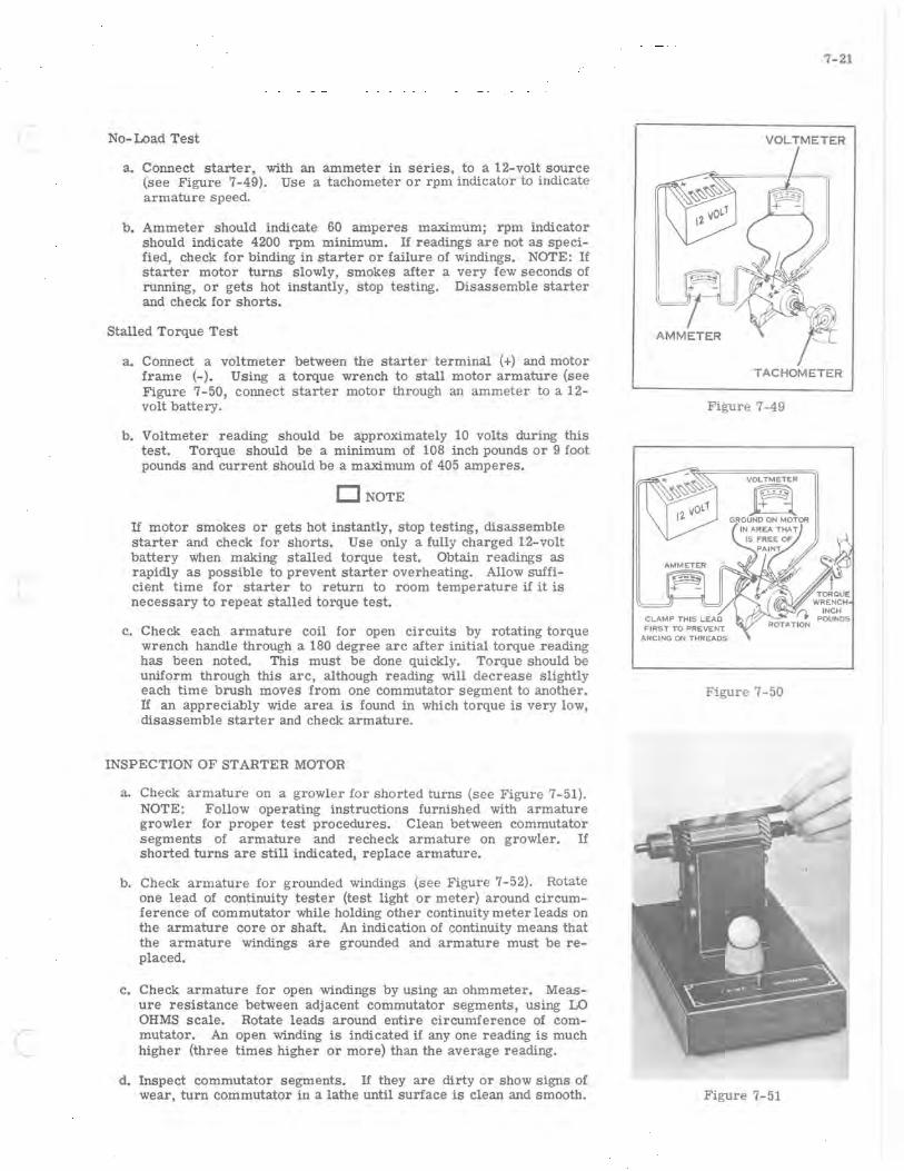
( No- Load Test
a. Connect starter, with an ammeter in series, to a 12-volt source (see Figure 7-49). Use a tachometer or rpm indicator to indicate armature speed.
b. Ammeter should indicate 60 amperes maximum; rpm indicator should indicate 4200 rpm minimum. If readings are not as specified, check for binding in starter or failure of windings. NOTE: If starter motor turns slowly, smokes after a very few seconds of running, or gets hot instantly, stop testing. Disassemble starter and check for shorts.
Stalled Torque Test
a. Connect a voltmeter between the starter terminal (+) and motor frame (-). Using a torque wrench to stall motor armature (see Figure 7-50, connect starter motor through an ammeter to a 12-volt battery.
b. Voltmeter reading should be approximately 10 volts during this test. Torque should be a minimum of 108 inch pounds or 9 foot pounds and current should be a maximum of 405 amperes.
DNOTE
If motor smokes or gets hot instantly, stop testing, disassemble starter and check for shorts. Use only a fully charged 12-volt battery when making stalled torque test. Obtain readings as rapidly as possible to prevent starter overheating. Allow sufficient time for starter to return to room temperature if it is necessary to repeat stalled torque test.
c. Check each armature coil for open circuits by rotating torque wrench handle through a 180 degree arc after initial torque reading has been noted. This must be done quickly. Torque should be uniform through this arc, although reading will decrease slightly each time brush moves from one commutator segment to another. If an appreciably wide area is found in which torque is very low, disassemble starter and check armature.
INSPECTION OF STARTER MOTOR
a. Check armature on a growler for shorted turns (see Figure 7-51). NOTE: Follow operating instructions furnished with armature growler for proper test procedures. Clean between commutator segments of armature and recheck armature on growler. If shorted turns are still indicated, replace armature.
b. Check armature for grounded windings (see Figure 7-52). Rotate one lead of continuity tester (test light or meter) around circumference of commutator while holding other continuity meter leads on the armature core or shaft. An indication of continuity means that the armature windings are grounded and armature must be replaced.
c. Check armature for open windings by using an ohmmeter. Measure resistance between adjacent commutator segments, using LO OHMS scale. Rotate leads around entire Circumference of commutator. An open winding is indicated if anyone reading is much higher (three times higher or more) than the average reading.
d. Inspect commutator segments. If they are dirty or show signs of wear, turn commutator in a lathe until surface is clean and smooth.
7-21
AMMETER
TACHOMETER
Figure 7-49
1~i + -GROUND ON MOTOR
Figure 7-50
Figure 7-51

7-22
Figure 7-52
INCORRECT
CORRECT
Figure 7-53
STARTER BELT
TENSION
Figure 7-54
e. After turning commutator, undercut insulation between commutator segments to a depth of approximately 1/32 inch. The undercut must be flat at the bottom (triangular groove cuts are unsatisfactory) and should extend beyond the brush contact area for the full length of each insulated groove (see Figure 7-53).
f. After commutator has been undercut, sand lightly with No. 00 sandpaper to remove burrs left during the undercutting process. After sanding, clean commutator thoroughly, removing all traces of metal chips or sanding grit, and recheck armature on growler.
g. Inspect armature insulation for indications of overheating or damaged windings. Clean off any deposits of carbon which may contribute to later failure of the windings. NOTE: Starter motor components should not be washed off in cleaning solvents. Most solvents will soften varnish insulation used on armature and field windings. All starter motor components can be cleaned adequately with a clean cloth or soft brush. Cleaning end heads in solvent may dissolve the oils that have impregnated into the armature shaft bearings. If these oils are removed, bearing or armature shaft wear can be expected. Cleaning of armature in solvent will leave oily residue on the commutator segments, causing arCing between the commutator and brushes.
Brushes
a. Inspect the brushes; replace if worn to one-third their original 3/8" length, or if damaged or cracked. Replace brush springs if weak.
b. Inspect brush springs. Springs should have a pressure of 35 to 90 ounces when compressed to 9/32 inch. Measure brush tension with scale hook under brush screw or under bend in brush spring, and take reading as brush just leaves commutator. Pull off spring scale must be directly opposite line of force exerted by brush spring.
BELT TENSION
a. Correct starter motor drive belt tension is extremely important. A loose belt will cause slippage and a tight belt will result in a ruined starter when it is driven overspeed by the engine after starting.
b. Install starter belt between starter and flywheel pulleys.
c. Turn movable half of pulley counterclockwise to drive position. See Figure 7-54.
d. Move starter down to tighten belt. Be certain that pulley halves are CLOSED or in driving position when making the adjustment.
e. Belt must be free when pulley is turned fully clockwise (engine run position).
ALTERNATOR
TROUBLE SHOOTING
Failure in the alternator charging circuit will usually show up when the headlights and taillights do not function, or when the battery fails to retain a charge sufficient to start the engine conSistently. To determine the cause of trouble, check the condition of the battery and electrical connections throughout the circuit, before proceeding with electrical testing. A visual inspection may be all that is required to locate the trouble.
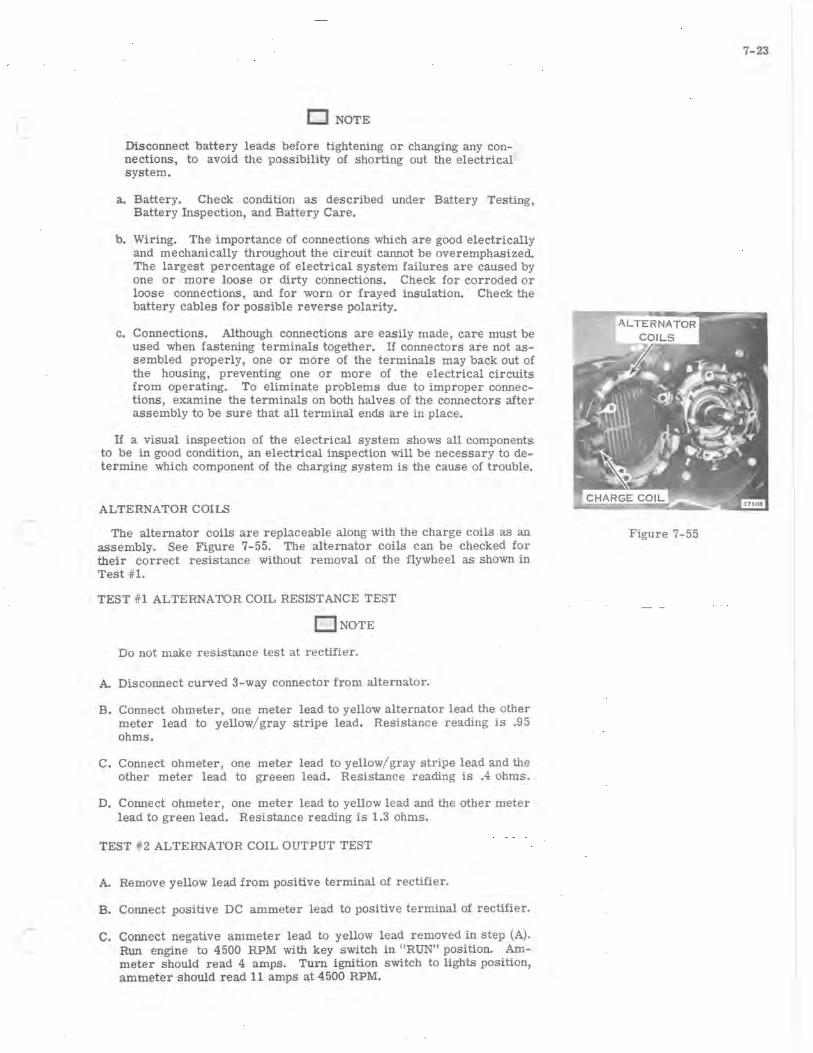
( D NOTE
Disconnect battery leads before tightening or changing any connections, to avoid the possibility of shorting out the electrical system.
a. Battery. Check condition as described under Battery Testing, Battery Inspection, and Battery Care.
b. Wiring. The importance of connections which are good electrically and mechanically throughout the circuit cannot be overemphasized. The largest percentage of electrical system failures are caused by one or more loose or dirty connections. Check for corroded or loose connections, and for worn or frayed insulation. Check the battery cables for possible reverse polarity.
c. Connections. Although connections are easily made, care must be used when fastening terminals together. If connectors are not assembled properly, one or more of the terminals may back out of the housing, preventing one or more of the electrical circuits from operating. To eliminate problems due to improper connections, examine the terminals on both halves of the connectors after assembly to be sure that all terminal ends are in place.
If a visual inspection of the electrical system shows all components to be in good condition, an electrical inspection will be necessary to determine which component of the charging system is the cause of trouble.
ALTERNATOR COILS
The alternator coils are replaceable along with the charge coils as an assembly. See Figure 7-55. The alternator coils can be checked for their correct resistance without removal of the flywheel as shown in Test #1.
TEST #1 ALTERNATOR COIL RESISTANCE TEST
o NOTE
Do not make resistance test at rectifier.
A. Disconnect curved 3-way connector from alternator.
B. Connect ohmeter, one meter lead to yellow alternator lead the other meter lead to yellow/ gray stripe lead. Resistance reading is .95 ohms.
C. Connect ohmeter, one meter lead to yellow/ gray stripe lead and the other meter lead to greeen lead. Resistance reading is .4 ohms.
D. Connect ohmeter, one meter lead to yellow lead and the other meter lead to green lead. Resistance reading is 1.3 ohms.
TEST #2 ALTERNATOR COIL OUTPUT TEST
A. Remove yellow lead from positive terminal of rectifier.
B. Connect positive DC ammeter lead to positive terminal of rectifier.
C. Connect negative ammeter lead to yellow lead removed in step (A). Run engine to 4500 RPM with key switch in "RUN" position. Ammeter should read 4 amps. Turn ignition switch to lights pOSition, ammeter should read 11 amps at 4500 RPM.
7-23
Figure 7-55
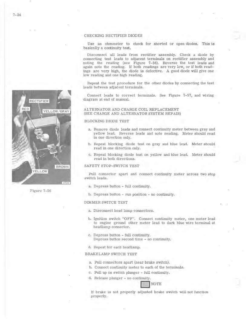
7-24
Figure 7-56
CHECKING RECTIFIER DIODES
Use an ohmmeter to check for shorted or open diodes. This is basically a continuity test.
Disconnect all leads from rectifier assembly. Check a diode by connecting test leads to adjacent terminals on rectifier assembly and noting the reading (see Figure 7-56). Reverse the test leads and again note the reading. If both readings are very lOW, or if both readings are very high, the diode is defective. A good diode will give one low reading and one high reading.
Repeat the test procedure for the other diodes by connecting the test leads between adjacent terminals.
Connect leads to correct terminals. See Figure 7-57, and wiring diagram at end of manual.
ALTERNATOR AND CHARGE COIL REPLACEMENT (SEE CHARGE AND ALTERNATOR SYSTEM REPAIR)
BLOCKING DIODE TEST
a. Remove diode leads and connect continuity meter between gray and yellow lead. Reverse leads and note reading. Meter should read in one direction only.
b. Repeat blocking diode test on gray and blue lead. Meter should read in one direction only.
c. Repeat blocking diode test on yellow and blue lead. Meter should read in both directions.
SAFETY STOP-SWITCH TEST
Pull connector apart and connect continuity meter across two stop switch leads.
a. Depress button - full continuity.
b. Depress button - run position - no continuity.
DIMMER SWITCH TEST
a. Disconnect head lamp connectors.
b. Ignition switch "OFF". Connect continuity meter, one meter lead to engine ground other meter lead to dark blue wire terminal at headlamp connector.
c. Depress button - full continUity. Depress button second time - no continUity.
d. Repeat for each headlamp.
BRAKE LAMP SWITCH TEST
a. Pull conneCtors apart (near brake switch). b. Connect continuity meter to each of the terminals. c. Pull up on switch plunger - full continuity.
d. Release plunger - no continuity.
n _ INOTE
If brake is not properly adjusted brake switch will not function properly.
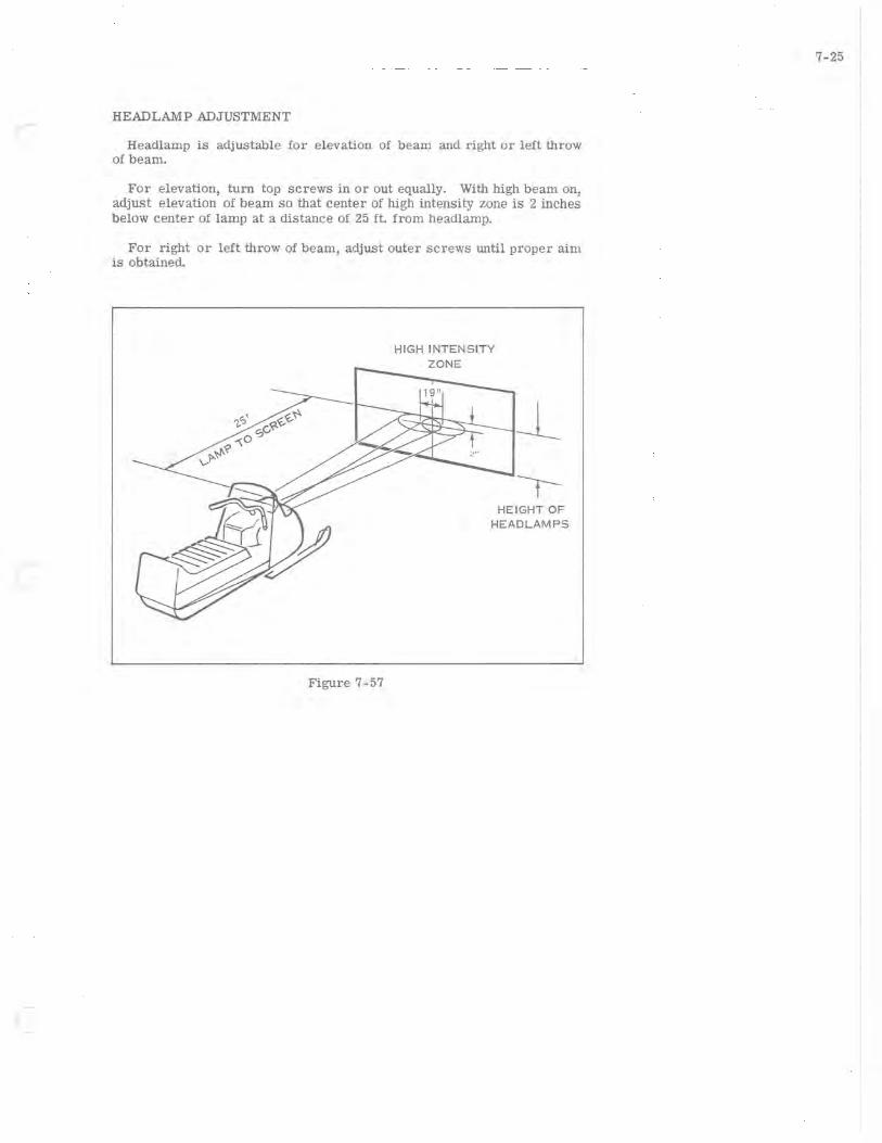
HEAD LAMP ADJUSTMENT
Headlamp is adjustable for elevation of beam and right or left throw of beam.
For elevation, turn top screws in or out equally. With high beam on, adjust elevation of beam so that center of high intensity zone is 2 inches below center of lamp at a distance of 25 ft. from headlamp.
For right or left throw of beam, adjust outer screws until proper aim is obtained.
Figure 7-57
HIGH INTENSITY ZONE
HEIGHT OF HEADLAMPS
7-25

..... )
8-1
SECTION a MANUAL STARTER
TABLE OF CONTENTS
DESCRIPTION. • • • • • • • • • • • • • • • • • • • • • 8-2
REMOVAL AND DISASSEMBLY. • • • • • . • . • 8-2
CLEANING, INSPECTION, AND REPAIR. •. • 8-3
REASSEMBLY •. . . • • • • • • • • • • • • • • • • . 8-3
STARTER ROPE REPLACEMENT • . • • • • • • 8-4
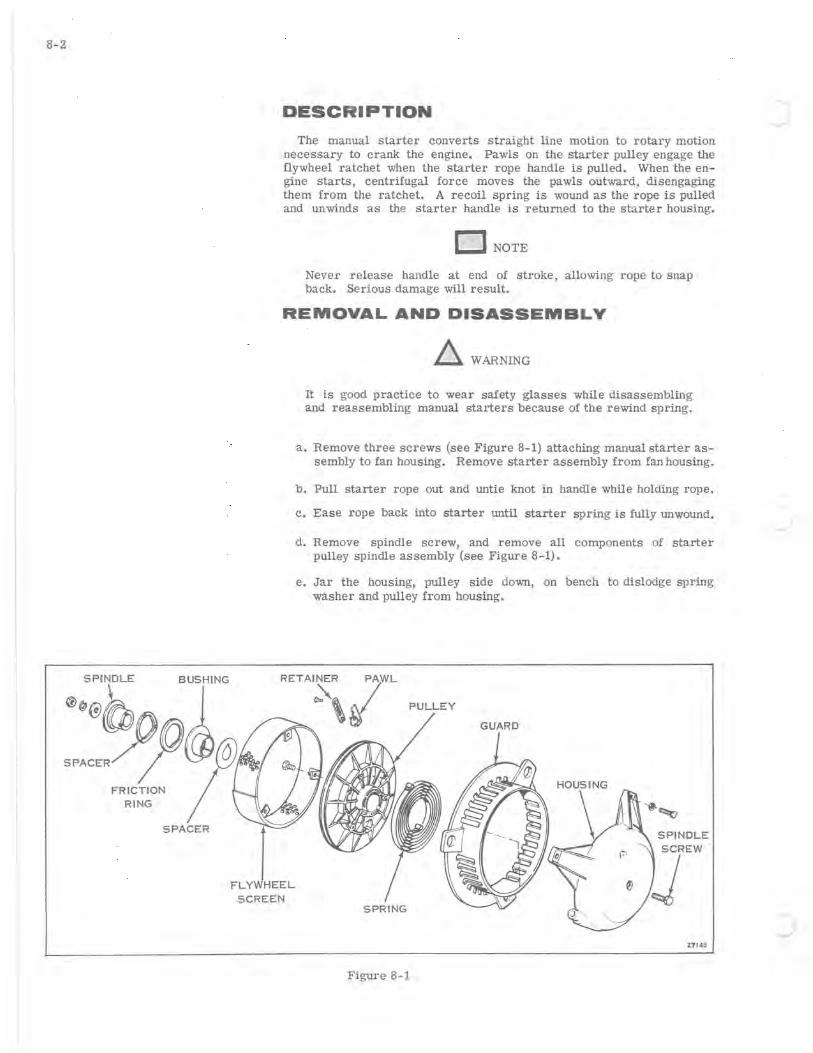
8-2
@:;b BUS],""
SPACER~'@@ FRICTION /
RING
SPACER
I
DESCRIPTION
The manual starter converts straight line motion to rotary motion necessary to crank the engine. Pawls on the starter pulley engage the flywheel ratchet when the starter rope handle is pulled. When the engine starts, centrifugal force moves the pawls outward, disengaging them from the ratchet. A recoil spring is wound as the rope is pulled and unwinds as the starter handle is returned to the starter housing.
o NOTE
Never release handle at end of stroke, allowing rope to snap back. Serious damage will result.
REMOVAL AND DISASSEMBLY
~ WARNING
It is good practice to wear safety glasses while disassembling and reassembling manual starters because of the rewind spring.
a. Remove three screws (see Figure 8-1) attaching manual starter assembly to fan housing. Remove starter assembly from fan housing.
b. Pull starter rope out and untie knot in handle while holding rope.
c. Ease rope back into starter until starter spring is fully unwound.
d. Remove spindle screw, and remove all components of starter pulley spindle assembly (see Figure 8-1).
e. Jar the housing, pulley side down, on bench to dislodge spring washer and pulley from housing.
PULLEY
SPINDLE
FLYWHEEL
SCREEN
Z7148
Figure 8-1
.J
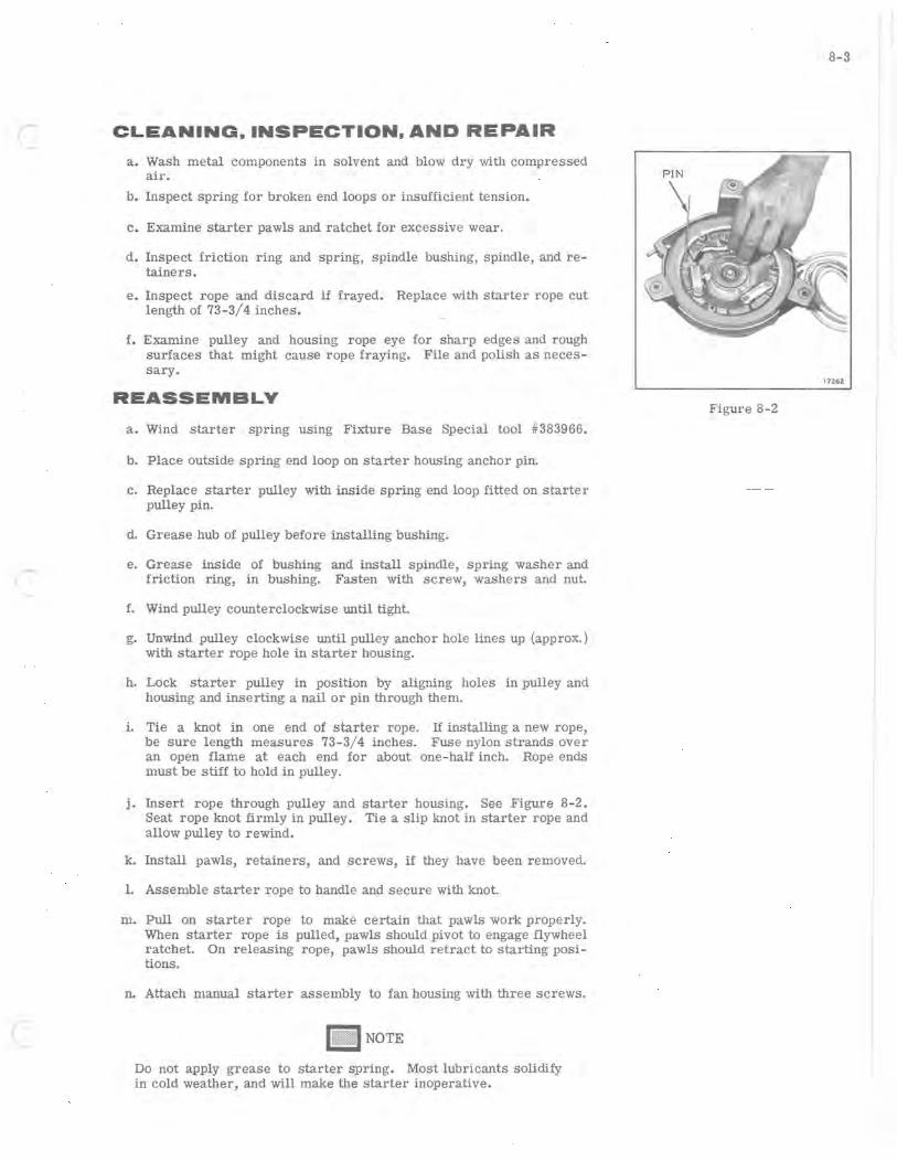
( CLEANING. INSPECTION, AND REPAIR
a. Wash metal components in solvent and blow dry with compressed air.
b. Inspect spring for broken end loops or insufficient tension.
c. Examine starter pawls and ratchet for excessive wear.
d. Inspect friction ring and spring, spindle bushing, spindle, and retainers.
e. Inspect rope and discard if frayed. Replace with starter rope cut length of 73-3/4 inches.
f. Examine pulley and housing rope eye for sharp edges and rough surfaces that might cause rope fraying. File and polish as necessary.
REASSEMBLY
a. Wind starter spring using Fixture Base Special tool #383966.
b. Place outside spring end loop on starter housing anchor pin.
c. Replace starter pulley with inside spring end loop fitted on starter pulley pin.
d. Grease hub of pulley before installing bushing.
e. Grease inside of bushing and install spindle, spring washer and friction ring, in bushing. Fasten with screw, washers and nut.
f. Wind pulley counterclockwise until tight.
g. Unwind pulley clockwise until pulley anchor hole lines up (approx.) with starter rope hole in starter housing.
h. Lock starter pulley in position by aligning holes in pulley and housing and inserting a nail or pin through them.
i. Tie a knot in one end of starter rope. If installing a new rope, be sure length measures 73-3/4 inches. Fuse nylon strands over an open flame at each end for about one-half inch. Rope ends must be stiff to hold in pulley.
j. Insert rope through pulley and starter housing. See Figure 8-2. Seat rope knot firmly in pulley. Tie a slip knot in starter rope and allow pulley to rewind.
k. Install pawls, retainers, and screws, if they have been removed.
1. Assemble starter rope to handle and secure with knot.
m. Pull on starter rope to make certain that pawls work properly. When starter rope is pulled, pawls should pivot to engage flywheel ratchet. On releasing rope, pawls should retract to starting positions.
n. Attach manual starter assembly to fan housing with three screws.
NOTE
Do not apply grease to starter spring. Most lubricants solidify in cold weather, and will make the starter inoperative.
8-3
17262
Figure 8-2

~

9-1
SECTION 9 ( ENGINE
DESCRIPTION ..................... 9-2
ENGINE REMOVAL . . . . . . . . . . . . . . . . .. 9-2
DISASSEMBLY. . . . . . . . . . . . . . . . . . . .. 9-3
CLEANING, INSPECTION, AND REPAIR. . .. 9-6 CYLINDERS . . . . . . . . . . . . . . . . . . .. 9-6 GASKETS AND GASKET SURFACES . . .. 9-6 PISTONS . . . . . . . . . . . . . . . . . . . . .. 9-6 BEARINGS . . . . . . . . . . . . . . . . . . . .. 9-7
ASSEMBLY OF ENGINE. . . . . . . . . . . . . .. 9-8 PISTONS, WRIST PINS, AND
CONNECTING RODS ............. 9-8 PISTON RINGS . . . . . . . . . . . . . . . . .. 9-8 CRANKSHAFT .................. 9-9 CYLINDERS ., .. ~ . . . . . . . . . . . . .. 9-10
INSTALLATION OF ENGINE. • . . • . . . . . •• 9-11 ASSEMBLY TO CHASSIS
BREAK-IN PROCEDURE. • . • • . . . . . . . • .. 9-11
MUFFLERS AND EXHAUST MANIFOLDS. • .• 9-12 REMOVAL •....•.•••••.•.•••. " 9-12 REASSEMBLY •.....••..••.....• 9-12
I
•
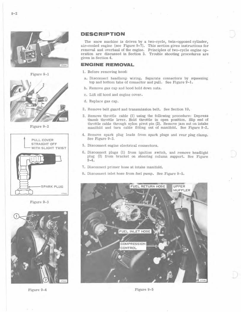
9-2
Figure 9-1
Figure 9-2
L PULL COVER STRAIGHT OFF WITH SLIGHT TWIST
A~~~:--SPARK PLUG
171 82
Figure 9-3
Figure 9-4
DESCRIPTION
The snow machine is driven by a two-cycle, twin- opposed cylinder, air-cooled engine (see Figure 9-7). This section gives instructions for removal and overhaul of the engine. Principles of two-cyCle engine operation are discussed in Section 3. Trouble shooting procedures are given in Section 4.
ENGINE REMOVAL
1. Before removing hood:
a. Disconnect headlamp WIrmg. Separate connectors by squeezing top and bottom tabs of connector and pull. See Figure 9-l.
b. Remove gas cap and hood hold down nuts.
c. Lift off hood and engine cover.
d. Replace gas cap.
2. Remove belt guard and transmission belt. See Section 10.
3. Remove throttle cable (1) using the following procedure: Depress thumb throttle lever. Hold throttle in open position. Slip end of throttle cable through nylon pivot pin (2). Remove jam nut on intake manifold and turn cable fitting out of manifold. See Figure 9-2.
4. Remove spark plug leads from spark plugs and rear plug clamp. See Figure 9-3.
5. Disconnect engine electrical connectors.
6. Disconnect plugs (1) from ignition switch, and remove headlight plug (2) from bracket on steering column support. See Figure 9-4.
7. Disconnect primer hose at intake manifold.
8. Disconnect inlet hose from fuel pump. See . Figure 9-5.
Figure 9-5
)
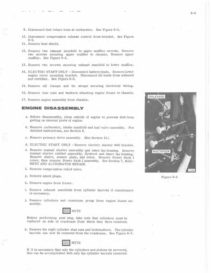
(~ 9. Disconnect fuel return hose at carburetor. See Figure 9-5.
10. Disconnect compression release control from bracket. See Figure 9-5.
11. Remove heat shield.
12. Remove two exhaust manifold to upper muffler screws. Remove two screws securing upper muffler to chassis. Remove upper muffler. See Figure 9-5.
13. Remove two screws securing exhaust manifold to lower muffler.
14. ELECTRIC START ONLY - Disconnect battery leads. Removelower engine cover mounting bracket. Disconnect all leads from solenoid and rectifier. See Figure 9-6.
15. Remove all clamps and tie straps securing electrical wiring.
16; Remove four nuts and washers attaching engine frame to chassis.
17. Remove engine assembly from chassis.
ENGINE DISASSEMBLY
a. Before disassembly, clean outside of engine to prevent dirt from getting on internal parts of engine.
b. Remove carburetor, intake manifold and leaf valve assembly. For detailed instructions, see Section 6.
c. Remove primary drive assembly. (See Section 10.)
d. ELECTRIC START ONLY - Remove electric starter with bracket.
e. Remove manual starter assembly and outer fan housing. Remove manual starter ratchet assembly, flywheel and inner fan housing. Remove stator, sensor plate, and rotor. Remove Power Pack I cover, then remove Power Pack I assembly. See Section 7, MAGNETO AND ALTERNATOR REPAIR
f. Remove compression relief valve.
g. Remove spark plugs.
h. Remove engine from frame.
i. Remove exhaust manifolds from cylinder barrels if maintenance is necessary.
j. Remove cylinders and crankcase group from engine frame assembly.
II1IU NOTE
Before performing next step, take note that cylinders must be replaced on side of crankcase from which they were removed.
k. Remove the eight cylinder stud nuts and lockwashers. The cylinder barrels can now be removed from the crankcase. See Figure 9-7.
na,,1 NOTE
If it is necessary that only the cylinders and pistons be serviced, this can be accomplished with only the cylinder barrels removed.
9-3
Figure 9-6
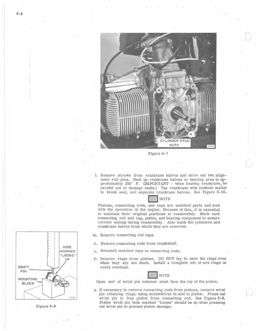
9-4
DRIFT PIN ----_11
MOUNTING
BLOCK -
Figure 9-8
SIDE MARKED "LOOSE"
17102
Figure 9-7
1. Remove screws from crankcase halves and drive out two alignment roll pins. Heat up crankcase halves in bearing area to approximately 250 0 F. (IMPORTANT - when heating crankcase, be careful not to damage seals.) Tap crankcase with rawhide mallet to break seal, and separate crankcase halves. See Figure 9-10.
1~i\. 1 NOTE
Pistons, connecting rods, and caps are matched parts and seat with the operation of the engine. Because of this, it is essential to maintain their original positions at reassembly. Mark each connecting rod and cap, piston, and bearing component to assure correct mating during reassembly. Also mark the cylinders and crankcase halves from which they are removed.
m. Remove connecting rod caps.
n. Remove connecting rods from crankshaft.
o. Reinstall matched caps on connecting rods.
p. Remove rings from pistons. DO NOT try to save the rings even when they are not stuck. Install a complete set of new rings on every overhaul.
I_ I NOTE
Open end of wrist pin retainer must face the top of the piston.
q. If necessary to remove connecting rods from pistons, remove wrist pin retaining rings, using screwdriver in slot in piston. Press out wrist pin to free piston from connecting rod. See Figure 9-8. Piston wrist pin hole marked "Loose" should be up when pressing out wrist pin to prevent piston damage.
L
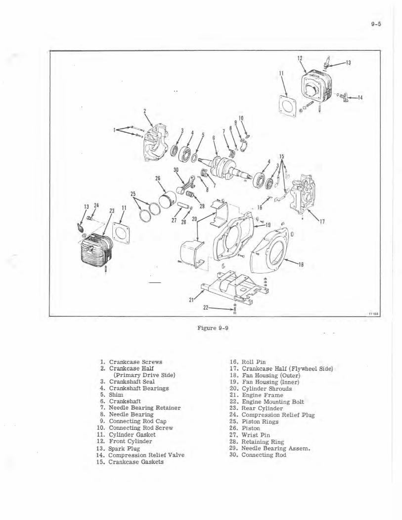
9-5
2
\ g10
'-<:::::-~ 1~3 'i 6 \\~ ~'(fJ l1 \ ~~ 15
~~@7'iS 43 " \b~~'~ 25 ~~'
11 ffiOJ17"~· ,( .
~a 27 28 20
,0' ,
17
18
21
17 103
Figure 9-9
1. Crankcase Screws 16. Roll Pin 2. Crankcase Half 17. Crankcase Half (Flywheel Side)
(Primary Drive Side) 18. Fan Housing (Outer) 3. Crankshaft Seal 19. Fan Housing (Inner) 4. Crankshaft Bearings 20. Cylinder Shrouds 5. Shim 21. Engine Frame 6. Crankshaft 7. Needle Bearing Retainer
22. Engine Mounting Bolt 23. Rear Cylinder
8. Needle Bearing 24. Compression Relief Plug 9. Connecting Rod Cap 25. Piston Rings
10. Connecting Rod Screw 26. Piston 11. Cylinder Gasket 27. Wrist Pin 12. Front Cylinder 28. Retaining Ring 13. Spark Plug 29. Needle Bearing Assem. 14. Compression Relief Valve 30. Connecting Rod 15. Crankcase Gaskets
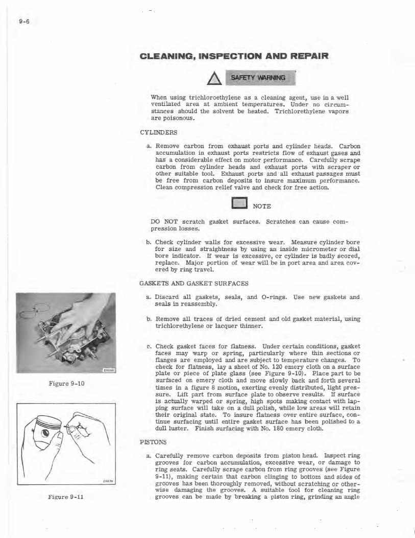
9-6
Figure 9-10
Z8B76
Figure 9-11
CLEANING, INSPECTION AND REPAIR
When using trichloroethylene as a cleaning agent, use in a well ventilated area at ambient temperatures. Under no circumstances should the solvent be heated. Trichlorethylene vapors are poisonous.
CYLINDERS
a. Remove carbon from exhaust ports and cylinder heads. Carbon accumulation in exhaus t ports restricts flow of exhaust gases and has a considerable effect on motor performance. Carefully scrape carbon from cylinder heads and exhaust ports with scraper or other s uitable tool. Exhaust ports and all exhaust passages must be free from carbon deposits to insure maximum performance. Clean compression relief valve and check for free action.
D NOTE
DO NOT scratch gasket surfaces. Scratches can cause compression losses.
b. Check cylinder walls for excessive wear. Measure cylinder bore for size and straightness by using an inside micrometer or dial bore indicator. If wear is excessive, or cylinder is badly scored, replace. Major portion of wear will be in port area and area covered by ring travel.
GASKETS AND GASKET SURFACES
a. Discard all gaskets, seals, and O- rings. Use new gaskets and seals in reassembly.
b. Remove all traces of dried cement and old gasket material, using trichlorethy lene or . lacquer thinner.
c. Check gasket faces for flatness. Under certain conditions, gasket faces may warp or spring, particularly where thin sections or flanges are employed and are subject to temperature changes. To check for flatness, lay a sheet of No. 120 emery cloth on a surface plate or piece of plate glass (see Figure 9-10). Place part to be surfaced on emery cloth and move slowly back and forth several times in a figure 8 motion, exerting evenly distributed, light pressure. Lift part from surface plate to observe results. If surface is actually warped or spring, high spots making contact with lapping surface will take on a dull pOlish, while low areas will retain their original state. To insure flatness over entire surface, continue surfacing until entire gasket surface has been polished to a dull luster. Finish surfacing with No. 180 emery cloth.
PISTONS
a. Carefully remove carbon deposits from piston head. Inspect ring grooves for carbon accumulation, excessive wear, or damage to ring seats. Carefully scrape carbon from ring grooves (see Figure 9- 11), making certain that carbon clinging to bottom and sides of grooves has been thoroughly removed, without scratching or otherwise damaging the grooves. A suitable fool for cleaning ring grooves can be made by breaking a piston ring, grinding an angle
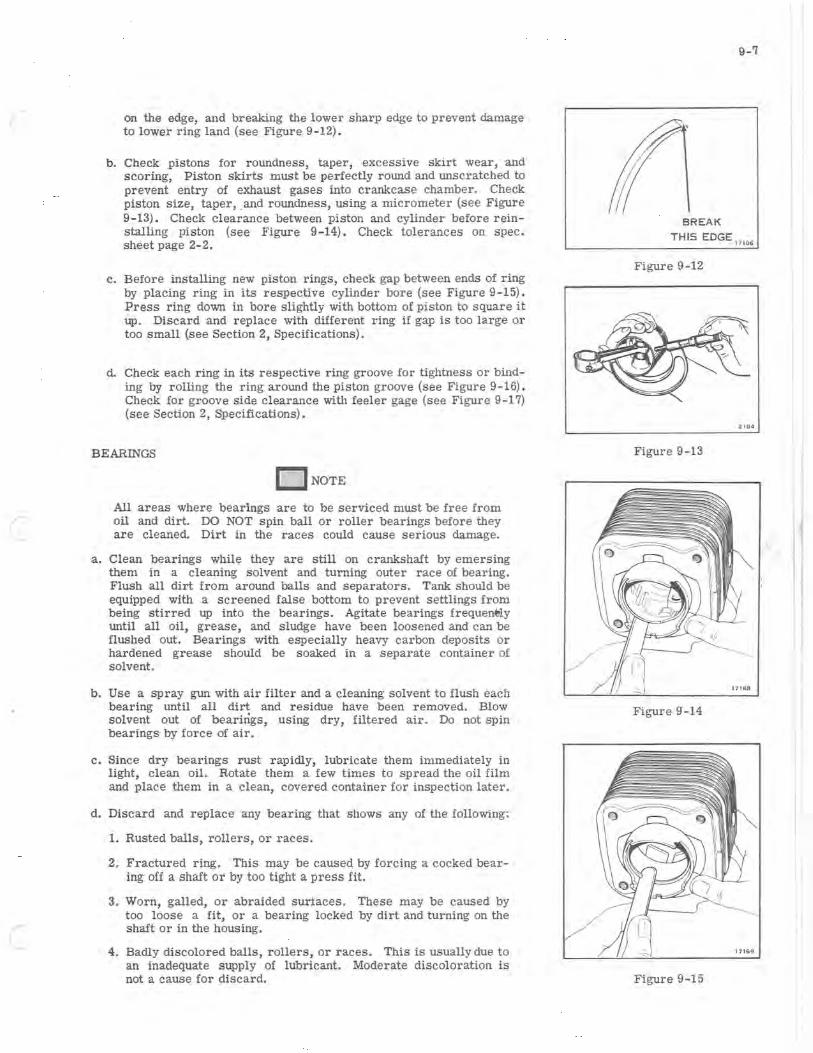
on the edge, and breaking the lower sharp edge to prevent damage to lower ring land (see Figure 9- 12).
b. Check pistons for roundness, taper, excessive skirt wear, and scoring, Piston skirts must be perfectly round and unscratched to prevent entry of exhaust gases into crankcase chamber. Check piston size, taper,. and roundness, using a micrometer (see Figure 9- 13). Check clearance between piston and cylinder before reinstalling piston (see Figure 9-14). Check tolerances on spec. sheet page 2-2.
c. Before installing new piston rings, check gap between ends of ring by placing ring in its respective cylinder bore (see Figure 9 -15). Press ring down in bore slightly with bottom of piston to square it Up. Discard and replace with different ring if gap is too large or too small (see Section 2, Specifications).
d. Check each ring in its respective ring groove for tightness or binding by rolling the ring around the piston groove (see Figure 9-16). Check for groove side clearance with feeler gage (see Figure 9-17) (see Section 2, Specifications).
BEARINGS
ONaTE
All areas where bearings are to be serviced must be free from oil and dirt. DO NOT spin ball or roller bearings before they are cleaned. Dirt in the races could cause serious damage.
a. Clean bearings while they are still on crankshaft by emersing them in a cleaning solvent and turning outer race of bearing. Flush all dirt from around balls and separators. Tank should be equipped with a screened false bottom to prevent settlings from being stirred up into the bearings. Agitate bearings frequer*ly until all oil, grease, and sludge have been loosened and can be flushed out. Bearings with especially heavy carbon deposits or hardened grease should be soaked in a separate container of solvent.
b. Use a spray gun with air filter and a cleaning solvent to flush each bearing until all dirt and residue have been removed. Blow solvent out of bearings, using dry, filtered air. Do not spin bearings by force of air.
c. Since dry bearings rust rapidly, lubricate them immediately in light, clean oil. Rotate them a few times to spread the oil film and place them in a clean, covered container for inspection later.
d. Discard and replace any bearing that shows any of the following:
1. Rusted balls, rollers, or races.
2. Fractured ring. This may be caused by forcing a cocked bearing off a shaft or by too tight a press fit.
3. Worn, galled, or abraided surtaces. These may be caused by too loose a fit, or a bearing locked by dirt and turning on the shaft or in the housing.
4. Badly discolored balls, rollers, or races. This is usually due to an inadequate supply of lubricant. Moderate discoloration is not a cause for discard.
BREAK
THIS EDGE
Figure 9-12
Figure 9-13
Figure 9-14
Figure 9-15
9-7
17106
2.104
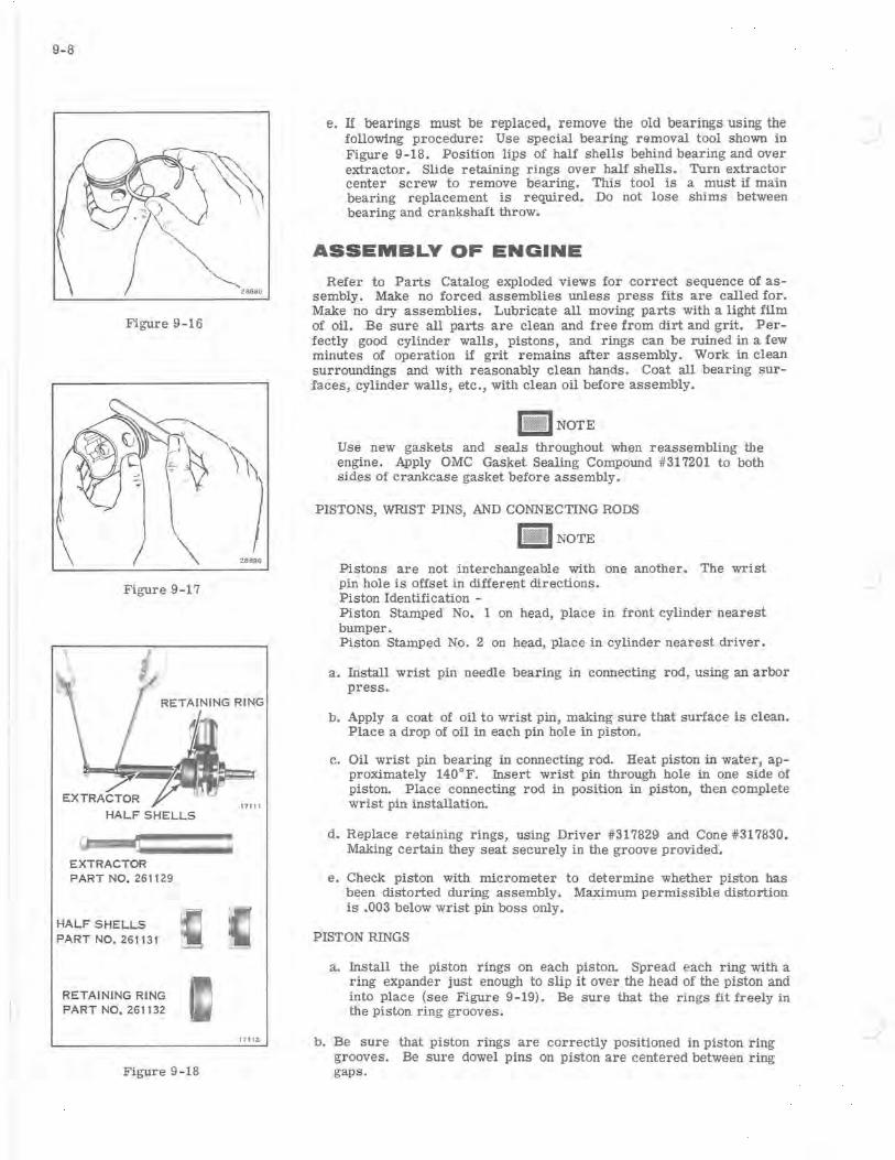
9-8
Figure 9-16
Figure 9-17
HALF SHELLS
EXTRACTOR PART NO. 261129
HALF SHELLS PART NO. 261131
RETAINING RING PART NO. 261132
Figure 9-18
28896
1711Z
e. If bearings must be replaced, remove the old bearings using the following procedure: Use special bearing removal tool shown in Figure 9-18. Position lips of half shells behind bearing and over extractor. Slide retaining rings over half shells. Turn extractor center screw to remove bearing. This tool is a must if main bearing replacement is required. Do not lose shims between bearing and crankshaft throw.
ASSEMBLY OF ENGINE
Refer to Parts Catalog exploded views for correct sequence of assembly. Make no forced assemblies unless press fits are called for. Make no dry assemblies. Lubricate all moving parts with a light film of oil. Be sure all parts are clean and free from dirt and grit. Perfectly good cylinder walls, pistons, and rings can be ruined in a few minutes of operation if grit remains after assembly. Work in clean surroundings and with reasonably clean hands. Coat all bearing surfaces, cylinder walls, etc., with clean oil before assembly.
Use new gaskets and seals throughout when reassembling the engine. Apply OMC Gasket Sealing Compound #317201 to both sides of crankcase gasket before assembly.
PISTONS, WRIST PINS, AND CONNECTING RODS
u lmJlNOTE
Pistons are not interchangeable with one another. The wrist pin hole is offset in different directions. Piston Identification -Piston Stamped No. 1 on head, place in front cylinder nearest bumper. Piston Stamped No.2 on head, place in cylinder nearest driver.
a. Install wrist pin needle bearing in connecting rod, using an arbor press.
b. Apply a coat of oil to wrist pin, making sure that surface is clean. Place a drop of oil in each pin hole in piston.
c. Oil wrist pin bearing in connecting rod. Heat piston in water, approximately 140°F. Insert wrist pin through hole in one side of piston. Place connecting rod in position in piston, then complete wrist pin installation.
d. Replace retaining rings, using Driver #317829 and Cone #317830. Making certain they seat securely in the groove provided.
e. Check piston with micrometer to determine whether piston has been distorted during assembly. Maximum permissible distortion is .003 below wrist pin boss only.
PISTON RINGS
a. Install the piston rings on each piston. Spread each ring with a ring expander just enough to slip it over the head of the piston and into place (see Figure 9-19). Be sure that the rings fit freely in the piston ring grooves.
b.Be sure that piston rings are correctly positioned in piston ring grooves. Be sure dowel pins on piston are centered between ring gaps.

-
Figure 9-19 Figure 9-20
CRANKSHAFT
I_ I NOTE
Shims must be installed on crankshaft, between the bearing and thrust face of crankshaft on flywheel end.
17153
a. Install crankshaft shims and journal bearings on crankshaft, using an arbor press. Be sure to support properly to prevent distortion. Shims must be installed on primary drive side (not magneto side) of crankshaft, between the bearing and the thrust face of crankshaft. Crankshaft end play should not exceed .019" after installation. Total dimension across bearings should be 4.933" ± .001". See Figure 9-20.
b. Remove connecting rod caps from connecting rods. Apply a coat of OMC Needle Bearing Grease (Part No. 378642) to connecting rod bearing area. Assemble needle bearing (16) and retainer halves, with connecting rod and connecting rod caps.
I- I NOTE
Connecting rod caps are matched. Do not interchange connecting rod caps or turn them end for end.
c. Assemble piston and rod assembly to crankshaft with piston ring dowel pins facing top of engine. Attach caps to connec~ing rods.
d. Draw sharp pencil down four machined corners of connecting rod and cap assembly to ensure proper alignment. (See Figure 9-21.) If not aligned offset edge will be felt with pencil point. If alignment is necessary, tap into alignment with drift punch. If alignment is satisfactory, tighten connecting rod cap screws to specified torque. '-I NOTE
It maybe necessary to heat crankcase halves for easier installation of crankshaft.
e. Spread film of OMC Gasket Sealing Compound #317201 to both sides of gaskets.
f. Insert screws and finger tighten. Insert roll pins, locate and drive in. Torque bolts to 1/2 required torque (2 - 3 ft. lb.). Final torque bolts to 5-7 ft. lb. Trim gasket material from open areas of crankcase.
g. Check crankshaft end play. It should not exceed .019".
9 - 9
Figure 9- 21

9-10
17 154
Figure 9-22
h. Crankshaft tapered end must be kept clean (free of grease .and fingerprints) before installation of primary sheave assembly.
i. Install crankshaft seals in crankcase.
CYLINDERS a. Install cylinders, using new gaskets. Use a ring compressor
(Special tool 426020) to install pistons in cylinders. Tighten nuts in correct sequence to specified torque. See Figure 9-22.
b. Install compression relief valve to forward cylinder using Dupage high temperature thread compound applied to the threads. Torque to specifications.
c. Attach cylinder and crankcase group to engine frame.
d. Install compression relief cable assembly and adjust. See Page 5-5.
e. Install inner fan housing with magneto and alternator, flywheel, and outer fan housing. ELECTRIC START ONLY - install starter motor belt. See Section 7 for belt adjusting procedure.
f. Install manual starter (see Section 8).
g. Install leaf valve assembly, intake manifold and carburetor. For detailed instructions, see Section 6. Apply OMC Gasket Sealing Compound #317201 on intake manifold gaskets.
h. ELECTRIC START ONLY - Install electric starter.
27145
Figure 9 - 23
1. Manifold Gaskets 6. Muffler Bracket Screw 2. Front Exhaust Manifold 7. Upper Muffler 3. Rear Exhaust Manifold 8. Manifold to Muffler Screw (2) 4. Muffler Gaskets 5. Manifold to Muffler Screw (2)
9. Lower Muffler Mounting screw (3)

INSTALLATION OF ENGINE ASSEMBLY TO CHASSIS
1. Assemble exhaust manifolds to cylinder barrels if they were removed. Use the following procedure:
a. Place new exhaust manifold gaskets over cylinder studs and then assemble front and rear exhaust manifolds. See Figure 9-24.
b. The gasket surfaces on cylinders and manifolds must be clean and smooth.
c. See page 2-3 for torque specifications.
2. Place lower muffler in well. Install engine and frame to chassis.
3. Install primary sheave assembly. See Section 10.
4. Install transmission belt. See Section 10.
5. Connect throttle cable. Adjust throttle lever so that throttle shutter is full open when throttle lever is in contact with handle grips.
6. Reconnect electrical connectors.
7. Install upper muffler and heat shield. Adjust upper muffler so there is clearance between exhaust pipe and outlet in chaSSis, and so that exhaust pipe does not extend more than 3/ 32" through chassis outlet.
8. Reconnect compression relief cable. See Section 5 for compression relief cable adjustment.
9. Install spark plugs and connect leads.
10. Reconnect fuel lines and throttle cable. See Section 6.
11. ELECTRIC START ONLY - Reconnect all leads to solenoid and rectifier. Replace lower engine cover mounting bracket. Reconnect battery leads.
12. Replace all clamps and install new tie straps securing electrical wiring. See FUEL LINE TIE STRAPS in Section 7.
13. Install hood in reverse order of removal.
BREAK-IN PROCEDURE
a. Be certain that when an engine is returned to service following an overhaul, the owner is advised to follow break-in procedures as described in the Owner's Manual exactly. This will allow the internal moving parts to seat themselves, thus greatly prolonging engine life.
b. For the first tankful of fuel the vehicle must be operated at reduced speeds.
c. Allow engine to warm up before putting vehicle in gear. Start out slowly; avoid jack- rabbit starts. DO NOT overspeed engine. Operation in extreme cold weather can cause a slow down in the drive and track mechanism. When this occurs, block up_ rear of snowmobile and place front edge of skis against stationary object and run to free mechanism. 00 NOT over-speed or run vehicle for prolonged periods as this can damage drive lugs on track.
9-11
9-12
d. Observe fuel mixing precautions as described in Section 12.
IMPORTANT
Adjust drive chain tension after the first 10 hours of operation. Refer to Section 10 for drive chain adjustment instructions.
Adjust track tension after the first 10 hours of operation. Refer to Section 11 for track tension and track alignment adjustment instructions.
MUFFLERS AND EXHAUST MANIFOLDS
REMOVAL
1. Disconnect positive battery lead for safety purposes. Remove engine cover, and lower engine cover mounting bracket.
2. Remove heat shield.
3. Remove belt guard and transmission belt. See Section 10.
4. Remove two screws (5) and two screws (6) and remove upper muffler (7) . Remove two screws (8) to disconnect lower muffler from manifold. See Figure 9-23. Remove Power Pack I engine cover.
5. Remove four engine mounting nuts and move engine a few inches to rear on chassis.
6. Remove steering tie rods from steering column bracket.
7. Remove three screws (9) securing lower muffler. Work muffler out of well.
REASSEMBLY
1. Reassemble in reverse order, first making sure mating surfaces are clean and smooth.
TABLE OF CONTENTS
DESCRIPTION. • • • • • . • . • • • • • . • • • • • •• 10-2
TRANSMISSION BELT INSPECTION AND REPLACEMENT. • • • • • • • • • • • • • •• 10-2
REMOVAL . • • • • • • • • • • • • • • • • • • •• 10-2 REPLACEMENT. • • • • • • • • • • • • • • •• 10-2
PRIMARY DRIVE. • . • • • . • • • • • • • • • • • .• 10-3 REMOV AL . . • • . • • • • • • • • • • • . • • •• 10-3 DISASSEMBLY. • • • • • • • • • • . • • • • • •• 10-3 CLEANING, INSPECTION AND REPAIR.. 10- 3 REASSEMBLY. • . • • • • • • • • • . • • • • •• 10-4
DRIVE CHAIN. • • • • • • . . . • • • • • • • • • • •• 10-5 LUBRICATION ••••••..•••.•.•••• 10-5 ADJUSTMENT •••••.••••••.•••.• 10- 5 REMOV AL • • • • • • • • • • • • • • • • • . • •• 10-5 INSTALLATION. • • • • • • • . . • . • • • • •• 10-5 REPAIR. • . . . • • • • . . • • • • • • • • • • •• 10- 5
BRAKE. • • • . • • • • • • • • • • • • • • • • • • • • • • 10-5 DESCRIPTION. • . • • • • • • • • • • • • • • •• 10- 5 REMOV AL • • . • . . • • • • • • • • • • • • . •• 10-5 REPAIR. • • • • • • • • . • . • • • • • • • • • •. 10-6 BRAKE CABLE & CAM ASSEMBLY •••• 10-6 ADJUSTMENT. . • • . . • . • . . . . • • • • •• 10-6
SECONDARY DRIVE .•••••••••••••••• 10-7 DISASSEMBLY. • . . • . . • . • • • • • • • • •• 10-7 CLEANING AND INSPECTION • • . • • • .• 10-8 REASSEMBLY. . . . . • . . • • • • • • • • • •• 10-8
10-1
SECTION 10 DRIVE TRAIN

"
10-2
o SECONDARY
OF SHEAVE
WORK BELT OUT FROM UNDER BOTTOM OF SHEAVE 2 702 2
DESCRIPTION This section gives complete service instructions on the snowmobile
drive train. A brief discussion of the power flow system is included in Section 3.
TRANSMISSION BELT INSPECTION & REPLACEMENT
A belt measuring less than 1-1/ 16" across the width or outer sur.face must be replaced with a new one. Worn belt may be retained and used as a spare. A spare belt should be carried at all times.
ED NOTE
DO NOT RUN ENGINE WITHOUT BELT.
BELT REMOVAL PROCEDURE (FIGURE 10-1)
A SAFETY WARNING
KEEP FINGERS FROM BETWEEN HALVES OF SECONDARY SHEAVE WHEN PERFORMING STEP 4.
WORK BELT BETWEEN END CAP
AND EXHAUST MANIFOLD 27023
Figure 10-1
r\ \ \ /
''''' ...
} i,/' // "J
PULL SLIDING SHEAVE WHILE TWISTING TO LEFT
....... -1 ~.--\\\
2. 70 19
\~ L· .>, . . / RIDE BELT OFF SHEAVE AS SHEAVE IS TWISTED TO RIGHT AND CLOSED
• 2.70 2 1
~~ ~Z·/" ..
\ '.
" '.
MOVE BELT BETWEEN ENGINE
ANDSECONDARYSHEAVE 2 MU
BELT REPLACEMENT PROCEDURE
Replace in reverse order of removal.
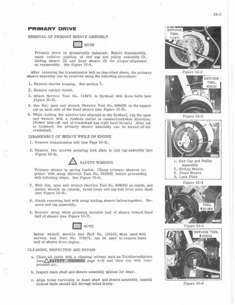
PRIMARY DRIVE
REMOVAL OF PRIMARY SHEAVE ASSEMBLY
o NOTE
Primary drive is dynamically balanced. Before disassembly, mark relative position of end cap and pulley assembly (1), sliding sheave (2) and fixed sheave (3) for proper alignment on reassembly. See Figure 10-4.
After removing the transmission belt as described above, the primary sheave assembly can be removed using the following procedure:
1. Remove starter housing. See section 7.
2. Remove ratchet mount.
3. Attach Service Tool No. 113971 to flywheel with three bolts (see Figure 10-2).
4. Use flat, open end wrench (Service Tool No. 404032) on the square nut on back side of the fixed sheave (see Figure 10- 3).
5. While holding the service tool attached to the flywheel, rap the open end wrench with a rawhide mallet in counterclockwise direction. (Power take-off end of crankshaft has right hand thread.) After nut is 10Qsened, the primary sheave assembly can be turned off the crankshaft.
DISASSEMBLY OF SHEAVE WHILE ON ENGINE
1. Remove transmission belt (see Page 10- 2).
2. Remove two screws securing lock plate to end cap assembly (see Figure 10-4).
~ SAFETY WARNING
Primary sheave is spring loaded. Clamp primary sheaves together with strap (Service Tool No. 261906) before proceeding with follOwing steps. See Figure 10- 5.
3. With flat, open end wrench (Service Tool No. 404032) on inSide, and socket wrench on outside, break loose end cap bolt from main shaft (see Figure 10- 6).
4. Finish removing bolt with strap holding sheave halves together. Re move end cap assembly.
5. Remove strap while pressing movable half of sheave toward fixed half of sheave (see Figure 10-7).
o NOTE
Spline wrench service tool Part No. 114146, when used with service tool Part No. 113971, can be used to remove fixed half of sheave from engine.
CLEANING, INSPECTION AND REPAIR
a . Clean all parts with a cleaning solvent such as Trichloroethylene (see.6.~l''tlafa1llllg page 9- 6) and blow dry with compressed air.
b. Inspect main shaft and sheave assembly splines for wear.
c . Align holes vertically in fixed shaft and sheave. assembly, neutral lockout balls should fall through holes freely.
10-3
Figure 10- 2
Figure 10- 3
1. End Cap and Pulley Assembly
2. Sliding Sheave 3. Fixed Sheave 4. Lock Plate
Figure 10-4
Figure 10-5
Figure 10-6
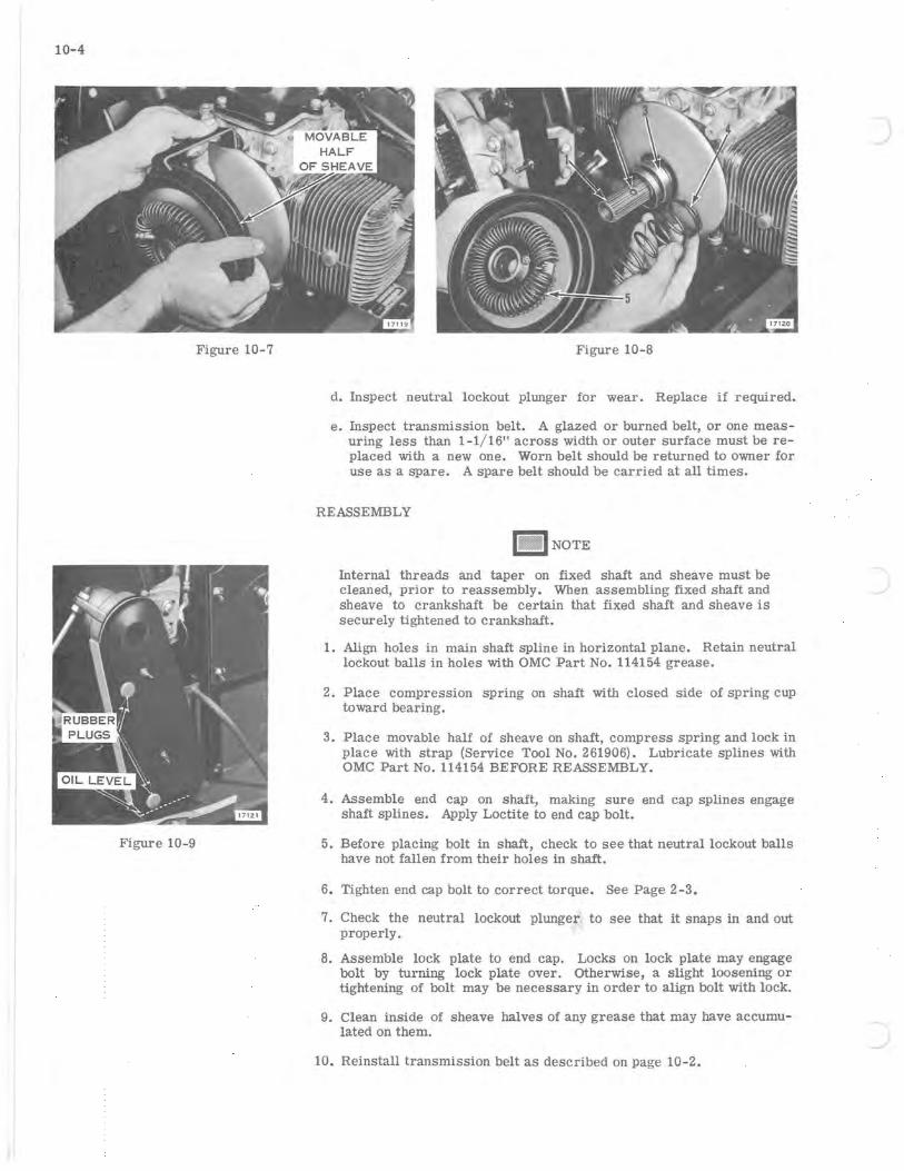
10- 4
Figure 10-7
Figure 10-9
Figure 10-8
d. Inspect neutral lockout plunger for wear. Replace if required.
e. Inspect transmission belt. A glazed or burned belt, or one measuring less than 1-1/16" across width or outer surface must be replaced with a new one. Worn belt should be returned to owner for use as a spare. A spare belt should be carried at all times.
REASSEMBLY
n . INOTE
Internal threads and taper on fixed shaft and sheave must be cleaned, prior to reassembly. When assembling fixed shaft and sheave to crankshaft be certain that fixed shaft and sheave is securely tightened to crankshaft.
1. Align holes in main shaft spline in horizontal plane. Retain neutral lockout balls in holes with OMC Part No. 114154 grease.
2. Place compression spring on shaft with closed side of spring cup toward bearing.
3. Place movable half of sheave on shaft, compress spring and lock in place with strap (Service Tool No. 261906). Lubricate splines with OMC Part No. 114154 BEFORE REASSEMBLY.
4. Assemble end cap on shaft, making sure end cap splines engage shaft splines. Apply Loctite to end cap bolt.
5. Before plaCing bolt in shaft, check to see that neutral lockout balls have not fallen from their holes in shaft.
6. Tighten end cap bolt to correct torque. See Page 2-3.
7. Check the neutral lockout plunger to see that it snaps in and out properly.
8. Assemble lock plate to end cap. Locks on lock plate may engage bolt by turning lock plate over. Otherwise, a slight loosening or tightening of bolt may be necessary in order to align bolt with lock.
9. Clean inside of sheave halves of any grease that may have accumulated on them.
10. Reinstall transmission belt as described on page 10-2.

DRIVE CHAIN
REMOVAL
I- I NOTE
Extreme caution should be taken when removing chain case cover, to overcome distortion of cover and damaging chain case.
1. Remove chain case cover. Oil will drain from chain case when cover is removed.
2. Loosen chain (see" Adjustment").
3. Remove cotter pin and nut from upper drive sprocket. (See Figure 10-10.)
4. Remove sprocket and chain from upper shaft.
5'. Chain can now be removed from lower sprocket.
INSTALLATION
1. Assemble in reverse order of disassembly.
2. Adjust chain per "Adjustment."
3. Add chain lubricant per "Lubrication."
ADJUSTMENT
Total slack must be 1/4" ± 1/16" as shown in Figure 10-10. To measure this distance, first remove the chain case cover. (Note: Oil will drain when cover is removed unless snowmobile is tilted on its side) . Place a straightedge over the chain at the sprockets, press in on the center of the chain and measure the slack at this point. If the chain requires adjustment, use the follOwing steps:
1. Loosen adjusting screw locknut (see Figure 10-11).
2. To tighten chain, pivot the eccentric adjustment downward.
3. To loosen chain, pivot eccentric adjustment upward.
LUBRICATION
The drive chain is lubricated by oil in the chain case. Should it be necessary to add oil use only OMC Type "C" and follow these instructions. Remove rubber plugs (top and bottom). Pour oil in top hole until it reaches level as shown in Figure 10-9. (It will hold approximately 4 oz.) Replace plugs.
BRAKE
DESCRIPTION
The brake is positive acting disc type with long lasting fibre pads (pucks).
REMOVAL
a. Loosen brake adjustment nut. See Figure 10-12.
b. Remove brake control cable from actuator cam arm.
10- 5
Figure 10-10
Figure 10-11
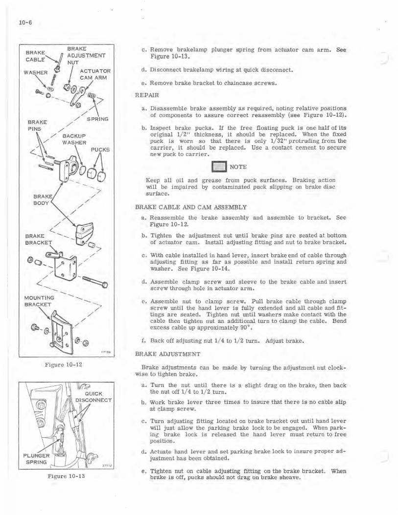
10-6
BRAKE
BRAKE':t ADJUSTMENT CABLE NUT
WASHER ~ ACTUATOR ~ I CAM ARM
~~ O:@~ o ____ ~~
BRAKE ./
./ SPRING
PINS ./
<.\._ ./ ./ BACKUP
-...~ -......-:;,-~
~
BODY
-MOUNTING --........ -.,.
/'
/' ./
/'
Figure 10-12
Figure 10-13
171 56
c. Remove brakelamp plunger spring from actuator cam arm. See Figure 10-13.
d. Disconnect brakelamp wiring at quick disconnect.
e. Remove brake bracket to chaincase screws.
REPAIR
a. Disassemble brake assembly as required, noting relative positions of components to assure correct reassembly (see Figure 10- 12) •
b. Inspect brake pucks. If the free floating puck is one half of its original 1/ 2" thickness, it should be replaced. When the fixed puck is worn so that there is only 1/ 32" protruding from the carrier, it should be replaced. Use a contact cement to secure new puck to carrier.
[J NOTE
Keep all oil and grease from puck surfaces. Braking action will be impaired by contaminated puck slipping on brake disc surface.
BRAKE CABLE AND CAM ASSEMBLY
a. Reassemble the brake assembly and assemble to bracket. See Figure 10-12.
b. Tighten the adjustment nut until brake pins are seated at bottom of actuator cam. Install adjusting fitting and nut to brake bracket.
c. With cable installed in hand lever, insert brake end of cable through adjusting fitting as far as possible and install return spring and washer. See Figure 10-14.
d. Assemble clamp screw and sleeve to the brake cable and insert screw through hole in actuator arm.
e. Assemble nut to clamp screw. Pull brake cable through clamp screw until the hand lever is fully extended and all cable and fittings are seated. Tighten nut until washers make contact with the cable then tighten nut an additional turn to clamp the cable. Bend excess cable up apprOximately 90°.
f. Back off adjusting nut 1/ 4 to 1/2 turn. Adjust brake.
BRAKE ADJUSTMENT
Brake adjustments can be made by turning the adjustment nut clockwise to tighten brake.
a. Turn the nut until there is a slight drag on the brake, then back the nut off 1/ 4 to 1/ 2 turn.
b. Work brake lever three times to insure that there is no cable slip at clamp screw.
c. Turn adjusting fitting located on brake bracket out until hand lever will just allow the parking brake lock to be engaged. When parking brake lock is released the hand lever must return to free position.
d. Actuate hand lever and set parking brake lock to insure proper adjustment has been obtained.
e. Tighten nut on cable adjusting fitting on the brake bracket. When brake is off, pucks should not drag on brake sheave.
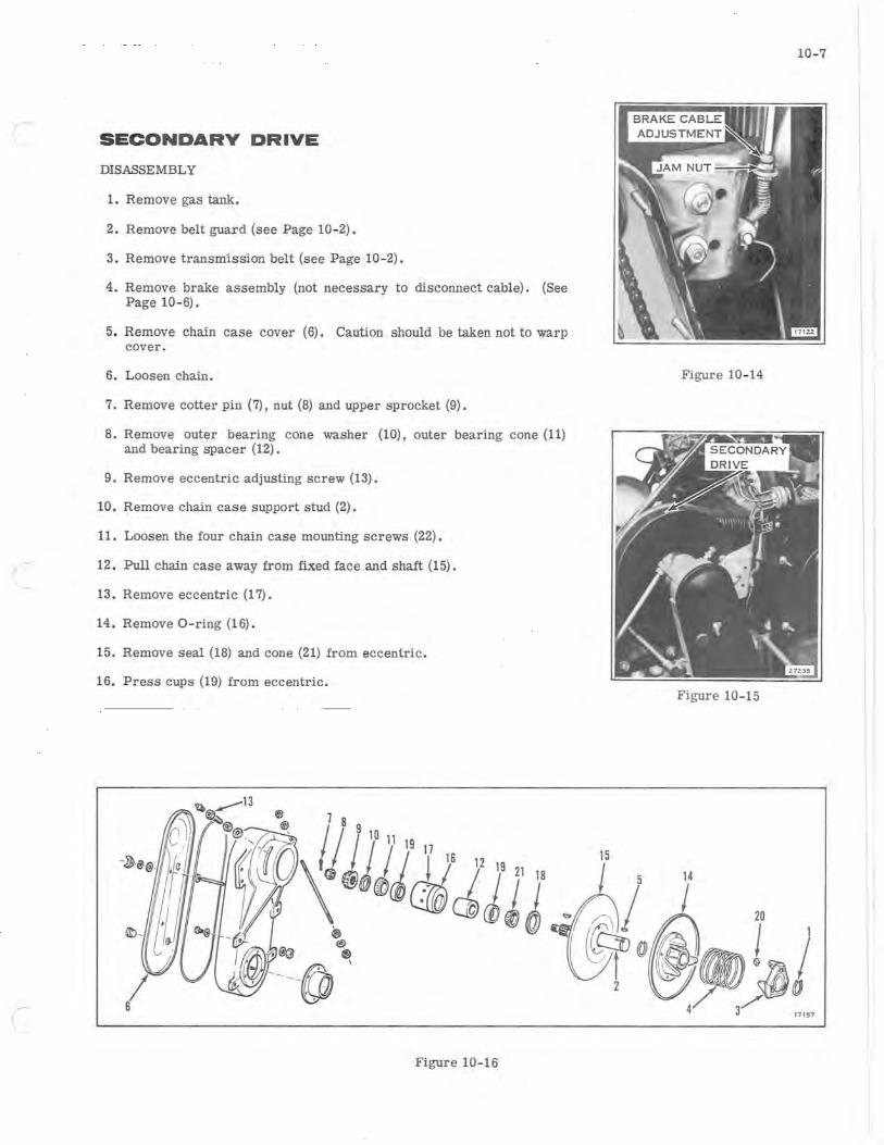
SECONDARY DRIVE
DISASSEMBLY
1. Remove gas tank.
2. Remove belt guard (see Page 10-2).
3. Remove transmission belt (see Page 10-2).
4. Remove brake assembly (not necessary to disconnect cable). (See Page 10- 6).
5. Remove chain case cover (6). Caution should be taken not to warp cover.
6. Loosen chain.
7. Remove cotter pin (7), nut (8) and upper sprocket (9).
8. Remove outer bearing cone washer (10), outer bearing cone (11) and bearing spacer (12).
9. Remove eccentric adjusting screw (13).
10. Remove chain case support stud (2).
11. Loosen the four chain case mounting screws (22).
12. Pull chain case away from fixed face and shaft (15).
13. Remove eccentric (17).
14. Remove O-ring (16).
15. Remove seal (18) and cone (21) from eccentric.
16. Press cups (19) from eccentric.
Figure 10-16
10-7
Figure 10- 14
Figure 10-15
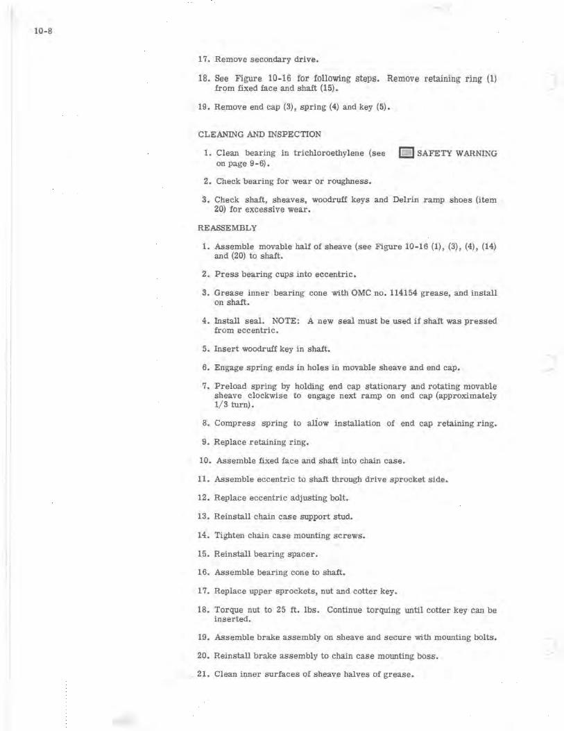
10-8
17. Remove secondary drive.
18. See Figure 10-16 for following steps. Remove retaining ring (1) from fixed face and shaft (15).
19. Remove end cap (3), spring (4) and key (5).
CLEANING AND INSPECTION
1. Clean bearing in trichloroethylene (see IDI SAFETY WARNING on page 9-6).
2. Check bearing for wear or roughness.
3. Check shaft, sheaves, woodruff keys and Delrin ramp shoes (item 20) for excessive wear.
REASSEMBLY
1. Assemble movable half of sheave (see Figure 10-16 (1) , (3), (4), (14) and (20) to shaft.
2. Press bearing cups into eccentric.
3. Grease inner bearing cone with OMC no. 114154 grease, and install on shaft.
4. Install seal. NOTE: A new seal must be used if shaft was pressed from eccentric.
5. Insert woodruff key in shaft.
6. Engage spring ends in holes in movable sheave and end cap.
7. Preload spring by holding end cap stationary and rotating movable sheave clockwise to engage next ramp on end cap (approximately 1/ 3 turn).
8. Compress spring to aliow installation of end cap retaining ring.
9. Replace retaining ring.
10. Assemble fixed face and shaft into chain case.
11. Assemble eccentric to shaft through drive sprocket side.
12. Replace eccentric adjusting bolt.
13. Reinstall chain case support stud.
14. Tighten chain case mounting screws.
15. Reinstall bearing spacer.
16. Assemble bearing cone to shaft.
17. Replace upper sprockets, nut and cotter key.
18. Torque nut to 25 ft. lbs. Continue torquing until cotter key can be inserted.
19. Assemble brake assembly on sheave and secure with mounting bolts.
20. Reinstall brake assembly to chain case mounting boss.
, 21. Clean inner surfaces of sheave halves of grease.
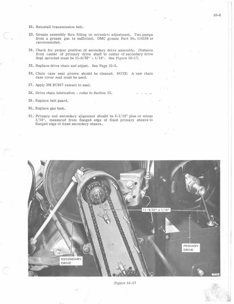
(
22. Reinstall transmission belt.
23. Grease assembly thru fitting on eccentric adjustment. Two pumps from a grease gun is sufficient. OMC grease Part No. 114154 is recommended.
24. Check for proper position of secondary drive assembly. Distance from center of primary drive shaft to center of secondary drive (top) sprocket must be 11-9/32" ± 1/16". See Figure 10-17.
25. Replace drive chain and adjust. See Page 10-5.
26. Chain case seal groove should be cleaned. NOTE: A new chain case cover seal must be used.
27. Apply 3M EC847 cement to seal.
28. Drive chain lubrication - refer to Section 12.
29. Replace belt guard.
30. Replace gas tank.
31. Primary and secondary alignment should be 2-1/16" plus or minus 1/16", measured from flanged edge of fixed primary sheave to flanged edge of fixed secondary sheave.
Figure 10-17
10-9

)
)
r
r
11-1
SECTION 11 STEERING, TRACK AND SUSPENSION
TABLE OF CONTENTS
DESCRIPTION. . . . . . . . . . . . . . . . . . . . .. 11-2
STEERING. . . . . . . . . . . . . . . . . . . . . . .. 11-2 DISASSEMBLY. . . . . . . . . . . . . . .. 11-2 CLEANING, INSPECTION, AND
REPAIR. . . . . . . . . . . . . . . . . . .. 11-2 REASSEMBLY ................ 11-2 SKI ALIGNMENT . . . . . . . . . . . . . .. 11- 2
TRACK AND SUSPENSION. . . . . . . . . . . . .. 11-3 TRACK TENSION ADJUSTMENT. . .. 11-3 TRACK ALIGNMENT ADJUSTMENT.. 11-3 REMOVAL OF TRUCKS AND TRACK. 11-4 FRONT AXLE DISASSEMBLY. . . . .. 11-4 REAR AXLE DISASSEMBLY . . . . . .. 11-5 TRUCK DISASSEMBLY. . . . . . . . . .. 11-5 CLEANING, INSPECTION, AND
REPAIR. . . . . . . . . . . . . . . . . . .. 11 - 5 Track. . . . . . . . . . . . . . . .. 11-5 Trucks and Axles ......... 11-5
REASSEMBLY ................ 11-6
III I
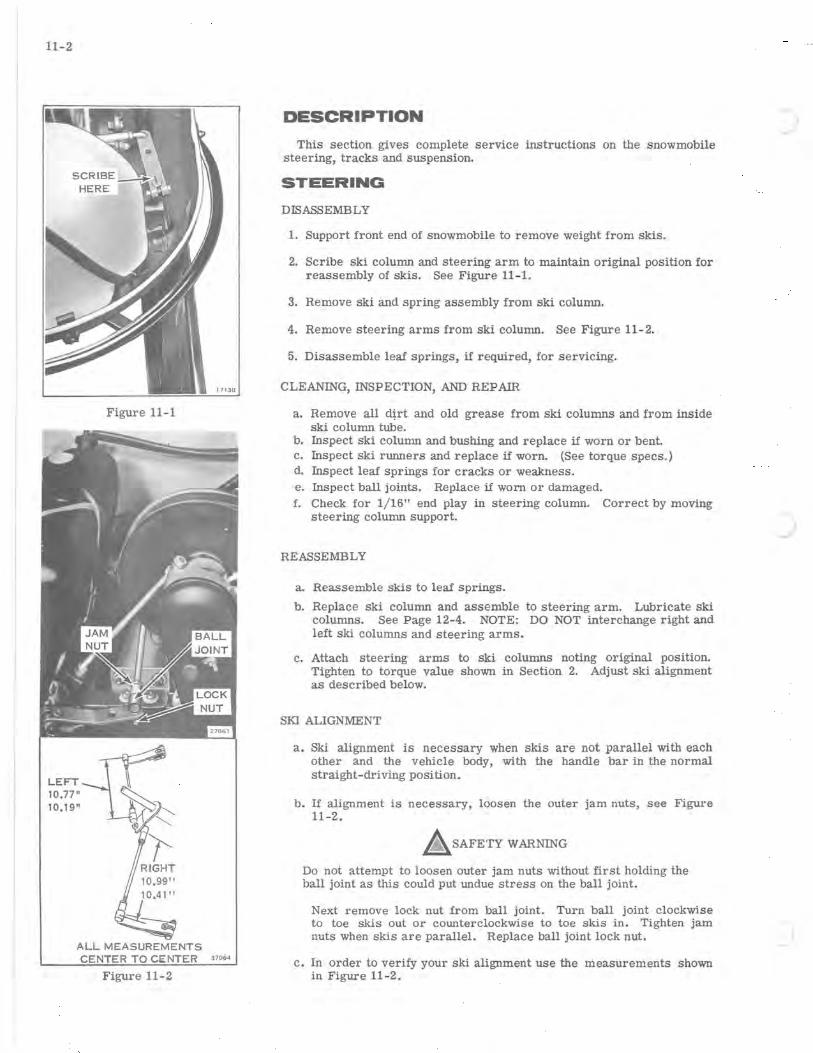
11-2
Figure 11-1
LEFT~ 10.77"
10.19" ~ ~
ALL MEASUREMENTS 37064
Figure 11-2
DESCRIPTION
This section gives complete service instructions on the snowmobile steering, tracks and suspension.
STEERING
DISASSEMBLY
1. Support front end of snowmobile to remove weight from skis.
2. Scribe ski column and steering arm to maintain original position for reassembly of skis. See Figure 11- 1.
3. Remove ski and spring assembly from ski column.
4. Remove steering arms from ski column. See Figure 11 - 2.
5. Disassemble leaf springs, if required, for servicing.
CLEANING, INSPECTION, AND REPAIR
a. Remove all d~rt and old grease from ski columns and from inside ski column tube.
b. Inspect ski column and bushing and replace if worn or bent. c. Inspect ski runners and replace if worn. (See torque specs.) d. Inspect leaf springs for cracks or weakness. e. Inspect ball joints. Replace if worn or damaged. f. Check for 1/16" end play in steering column. Correct by moving
steering column support.
REASSEMBLY
a. Reassemble skis to leaf springs.
b. Replace ski column and assemble to steering arm. Lubricate ski columns. See Page 12-4. NOTE: DO NOT interchange right and left ski columns and steering arms.
c. Attach steering arms to ski columns noting original position. Tighten to torque value shown in Section 2. Adjust ski alignment as described below.
SKI ALIGNMENT
a. Ski alignment is necessary when skis are not parallel with each other and the vehicle body, with the handle bar in the normal straight-driving position.
b. If alignment is necessary, loosen the outer jam nuts, see Figure 11-2.
.. SAFETY WARNING
Do not attempt to loosen outer jam nuts without first holding the ball joint as this could put undue stress on the ball joint.
Next remove lock nut from ball joint. Turn ball joint clockwise to toe skis out or counterclockwise to toe skis in. Tighten jam nuts when skis are parallel. Replace ball joint lock nut.
c. In order to verify your ski alignment use the measurements shown in Figure 11-2.
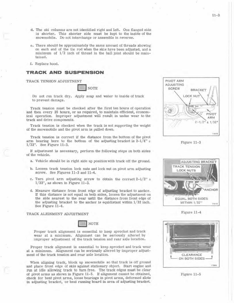
(
(
d. The ski columns are not identified right and left. One flanged side is shorter. This shorter side must be kept to the inside of the snowmobile. Do not interchange or assemble in reverse.
e. There should be approximately the same amount of threads shOwing on each end of the tie rod when the skis have been adjusted, and a minimum of 1/2 inch of thread in the ball joint should be maintained.
f. Replace hood.
TRACK AND SUSPENSION
TRACK TENSION ADJUSTNENT
1 ~;;!l 1 NOTE
Do not run track dry. Apply soap and water to inside of track to prevent damage.
Track tension must be checked after the first ten hours of operation and then every 25 hours, or as required, to maintain efficient, economical operation. Improper adjustment will result in undue wear to the track and drive components.
Track tension is checked when the track is not supporting the weight of the snowmobile and the pivot arm is pulled down.
Track tension is correct if the distance from the bottom of the pivot arm bearing bore to the bottom of the adjusting bracket is 2-1/4" ± 1/32". See Figure 11-3.
If adjustment is necessary, perform the following steps on both sides of the vehicle.
a. Vehicle should be in right side up position with track off the ground.
b. Loosen track tension lock nuts and lock nut on pivot arm adjusting screw. See Figures 11-3 and 11-4.
c. Turn pivot arm adjusting screw to obtain the correct 2-1/2" ± 1/32", as shown in Figure 11-3.
d. Measure distance from front edge of adjusting bracket to anchor. If this distance is not equal on both Sides, loosen the adjustment on the side nearest to the rear until the distance from front edge of the adjusting bracket to the anchor is equidistant within 1/32 inch. See Figure 11-4.
TRACK ALIGNMENT ADJUSTMENT
I- I NOTE
Proper track alignment is essential to keep sprocket and track wear at a minimum. Alignment can be seriously altered by improper adjustment of the track tension and rear axle location.
Proper track alignment is essential to keep sprocket and track wear at a minimum. Alignment can be seriously altered by improper adjustment of the track tension and rear axle location.
When aligning track, block up snowmobile so that track is off ground and place front edge of skis against stationary object. Start engine and run at idle allowing track to turn free. The track edges must be clear of pivot arms as shown in Figure 11-5. If alignment cannot be obtained, check for bent pivot arms, loose bearings in pivot arms, deformed slots in adjusting bracket, or bent rwming board in area of adjusting bracket.
11-3
PIVOT ARM
2- 1/ 2" ± 1/32"
Figure 11-3
EQUAL BOTH SIDES WITHIN 1/ 32"
Figure 11-4
Figure 11-5
17018
17019
17005
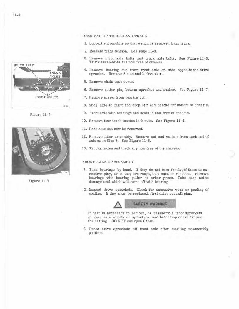
11-4
17 160
Figure 11-6
Figure 11-7
REMOVAL OF TRUCKS AND TRACK
1. Support snowmobile so that weight is removed from track.
2. Release track tension. See Page 11-3.
3. Remove pivot axle bolts and truck axle bolts. See Figure 11 - 6. Truck assemblies are now free of chassis.
4. Remove bearing cup from front axle on side opposite the drive sprocket. Remove 3 nuts and lockwashers.
5. Remove chain case cover.
6. Remove cotter pin, bottom sprocket and washer. See Figure 11 - 7.
7. Remove screw from bearing cup.
8. Slide axle to right and drop left end of axle out bottom of chassis.
9. Front axle with bearings and seals is now free of chassis.
10. Remove four track tension lock nuts. See Figure 11-4.
11. Rear axle can now be removed.
12. Remove idler assembly. Remove nut and washer from each end of axle as in Step 3. See Figure 11-6.
13. Trucks, axles and track are now free of the chassis.
FRONT AXLE DISASSEMBLY
1. Turn bearings by hand. If they do not turn freely, if there is excessive play, or if they are rough, they must be replaced. Remove bearings with bearing puller or arbor press. Take care not to damage seal which will come off with bearing.
2. Inspect drive sprockets. Check for excessive wear or peeling of coating. If they must be replaced, first drive out roll pins.
If heat is necessary to remove, or reassemble front sprockets or rear axle wheels or sprockets, use heat lamp or hot air gun for heating. DO NOT use open flame.
3. Press drive sprockets off front axle after marking reassembly position.
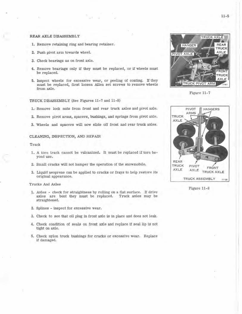
( REAR AXLE DISASSEMBLY
1. Remove retaining ring and bearing retainer.
2. Push pivot arm towards wheel.
3. Check bearings as on front axle.
4. Remove bearings only if they must be replaced, or if wheels must be replaced.
5. Inspect wheels for excessive wear, or peeling of coating. If they must be replaced, first loosen Allen set screws to remove wheels from axle.
TRUCK DISASSEMBLY (See Figures 11 - 7 and 11-8)
1.. Remove lock nuts from front and rear truck axles and pivot axle.
2. Remove pivot arms, spacers, bushings, and springs from pivot axle.
3. Wheels and spacers will now slide off front and rear truck axles.
CLEANING, INSPECTION, AND REPAIR
Track
1. A torn track cannot be vulcanized. It must be replaced if torn beyond use.
2. Small cracks will not hamper the operation of the snowmobile.
3. Liquid neoprene can be applied to cracks or frays to help restore its original appearance.
Trucks And Axles
1. Axles - check for straightness by rolling on a flat surface. If drive axles are bent they must be replaced. Truck axles may be straightened.
2. Splines - inspect for excessive wear.
3. Check to see that oil plug in front axle is in place and does not leak.
4. Check condition of seals on front axle and replace if seal lip is not tight on axle.
5. Check nylon truck bushings for cracks or excessive wear. Replace if damaged.
AXLE
11-5
Figure 11-7
FRONT AX L E TRUCK AXLE
TRUCK ASSEMBLY 17 132
Figure 11-8
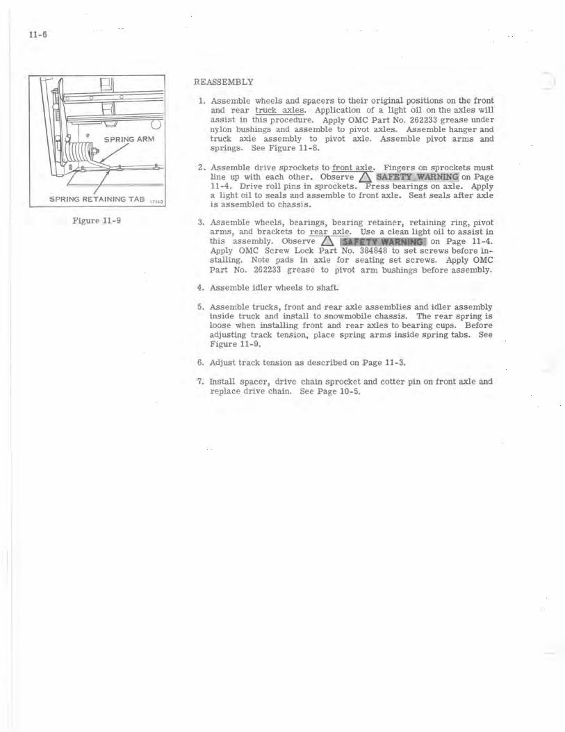
11-6
SPRING RETAINING TAB 171 6 3
Figure 11-9
REASSEMBLY
1. Assemble wheels and spacers to their original positions on the front and rear truck axles. Application of a light oil on the axles will assist in this procedure. Apply OMC Part No. 262233 grease under nylon bushings and assemble to pivot axles. Assemble hanger and truck axle assembly to pivot axle. Assemble pivot arms and springs. See Figure 11-8.
2. Assemble drive sprockets to front axle. Fingers on sprockets must line up with each other. Observe ~ .~1.~4"" on Page 11-4. Drive roll pins in sprockets. Press bearings on axle. Apply a light oil to seals and assemble to front axle. Seat seals after axle is assembled to chassis.
3. Assemble wheels, bearings, bearing retainer, retaining ring, pivot arms, and brackets to rear axle. Use a clean light oil to assist in this assembly. Observe ZS on Page 11-4. Apply OMC Screw Lock Part No. 384848 to set screws before installing. Note pads in axle for seating set screws. Apply OMC Part No. 262233 grease to pivot arm bushings before assembly.
4. Assemble idler wheels to shaft.
5. Assemble trucks, front and rear axle assemblies and idler assembly inside truck and install to snowmobile chassis. The rear spring is loose when installing front and rear axles to bearing cups. Before adjusting track tenSion, place spring arms inside spring tabs. See Figure 11-9.
6. Adjust track tension as described on Page 11-3.
7. Install spacer, drive chain sprocket and cotter pin on front axle and replace drive chain. See Page 10-5.
-

SECTION 12 LUBRICATION AND STORAGE
TABLE OF CONTENTS
ENGINE LUBRICATION. • • • . • • • • . . • . •• 12-2 OMC 2+4 FUEL CONDITIONER •••••.• 12-2 FUEL BLENDING • • • • . • .• . • • • • • . • 12-3
LUBRICATION RECOMMENDATIONS. • • • •• 12-4
PREVENTIVE MAINTENANCE •••.•••••• 12-5 AIR FILTER. • . • . • • • • • • • • • • . • • •• 12-5 FUEL FILTERSCREEN, FUEL PUMP •• 12-5 FUEL FILTER SCREEN,
CARBURETOR • • • • • . • • • . • . . • • •. 12- 5
STORAGE •••• . • • • • • • • • • • . . • • • • . •• 12-6
-
PREPARATION FOR STORAGE. • • • • •• 12- 6 REMOVAL FROM STORAGE • • • • • • • •• 12-6
12-1

12- 2
ENGINE LUBRICATION
Since fuel vapors are first compressed in the crankcase of the twocycle engine, the most practical method of lubrication is by mixing the lubricant with the gasoline. As the mixture of lubricant and gasoline enters the crankcase, the gasoline is vaporized, leaving the lubricant to lubricate the bearings and other moving parts. Eventually the lubricant reaches the combustion chamber where it is burned and discharged through the exhaust ports. In this way the fuel mixture conveys to the engine's moving parts a metered amount of lubricant in proportion to the speed of the engine.
Both optimum performance and lubrication depend on maintaining the correct ratio between gasOline and lubricant in the fuel mixture. The use of too little lubricant leads to premature wear and early breakdown. A fuel mixture richer in lubricant than recommended is not only wasteful but will contribute to faulty performance, and to excessive carbon accumulation in the cylinders and on the spark plugs. Frequent spark plug replacement can often be t r aced to an excess of lubricant in the fuel mixture. Instructions for the mixing of fuel during break- in and normal operation as given here and in the Owner's Manual should be followed exa.ctly.
The use of additive compounds, such as tune- up compounds, tonics, friction reducing compounds, etc. , is discouraged. OMC Accessories Engine Cleaner and OMC Accessories Break-In Lubricant should be used as necessary according to instructions. See inside front cover for recommended fuel mixture.
OMC 2+4 FUEL CONDITIONER
OMC 2+4 Fuel Conditioner is recommended for added protection to your snowmobile engine. It is especially -recommended as an additive between extended periods of snowmobile use. OMC 2+4 Fuel Conditioner is available from your dealer.
OMC 2+4 Fuel Conditioner features are as follows:
• Fuel Stabilizer - prevents formation of gum and varnish deposits in fuel system for one year of storage. Eliminates need for draining fuel for storage.
• Carburetor Cleaner - dissolves gum and varnish depOSits in carburetor and fuel system.
• Corrosion Resistance - protects carburetor, fuel system and internal engine parts from corrosion.
• De- icer - prevents carburetor icing and gas line freezeup.
• Absorbs moisture and water in fuel system.
• Extends spark plug life by redUCing fouling and misfire.
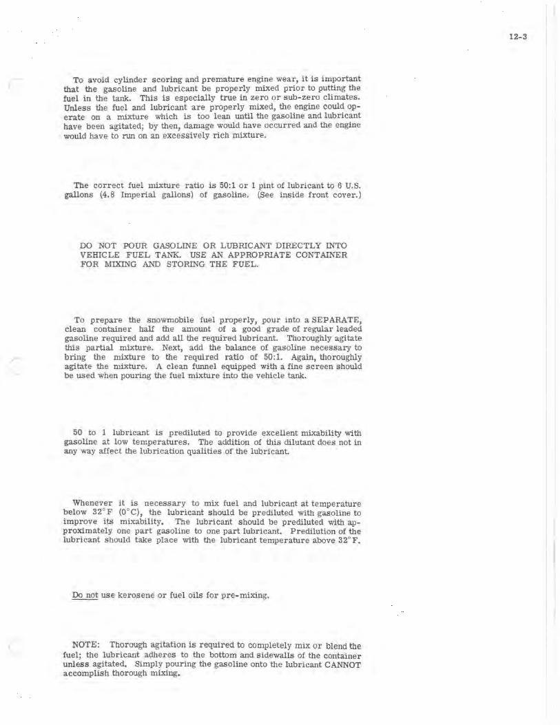
(
To avoid cylinder scoring and premature engine wear, it is important that the gasoline and lubricant be properly mixed prior to putting the fuel in the tank. This is especially true in zero or sub-zero climates. Unless the fuel and lubricant are properly mixed, the engine could operate on a mixture which is too lean until the gasoline and lubricant have been agitated; by then, damage would have occurred and the engine would have to run on an excessively rich mixture.
The correct fuel mixture ratio is 50:1 or 1 pint of lubricant to 6 U.S. gallons (4.8 Imperial gallons) of gasoline. (See inside front cover.)
DO NOT POUR GASOLINE OR LUBRICANT DIRECTLY INTO VEHICLE FUEL TANK. USE AN APPROPRIATE CONTAINER FOR MIXING AND STORING THE FUEL.
To prepare the snowmobile fuel properly, pour into a SEPARATE, clean container half the amount of a good grade of regular leaded gasoline required and add all the required lubricant. Thoroughly agitate this partial mixture. Next, add the balance of gasoline necessary to bring the mixture to the required ratio of 50:1. Again, thoroughly agitate the mixture. A clean funnel equipped with a fine screen should be used when pouring the fuel mixture into the vehicle tank.
50 to 1 lubricant is prediluted to provide excellent mixability with gasoline at low temperatures. The addition of this dilutant does not in any way affect the lubrication qualities of the lubricant.
Whenever it is necessary to mix fuel and lubricant at temperature below 32° F (O °C), the lubricant should be prediluted with gasoline to improve its mixability. The lubricant should be prediluted with approximately one part gasOline to one part lubr icant. Predilution of the lubricant should take place with the lubricant temperature above 32°F.
Do not use kerosene or fuel oils for pre- mixing.
NOTE: Thorough agitation is required to completely mix or blend the fuel; the lubricant adheres to the bottom and sidewalls of the container unless agitated. Simply pouring the gasOline onto the lubricant CANNOT accomplish thorough mixing.
12- 3

12-4
LUBRICATION RECOMMENDATIONS
3 7349
TIME MAINTENANCE LUBRICANT
ffi Every 25 hrs. Ski Pivots (Leaf spring connections to skis) SAE 10 Oil Once a season Ski columns (grease fittings). OMC Grease #114154
@ After 10 hrs. then Drive Chain - oil bath - Refer to Page 14 OMC Type C every 25 hrs.
® Once a season Secondary Drive (grease fitting. Two pumps of grease OMC Grease #114154
® gun).
Once a season Primary Drive (grease fitting - 1/ 3 to 1/ 2 teaspoon. OMC Grease #114154 (normal use) Do not over lubricate).
Twice a season (extended use)
Specified lubricants available from your dealer
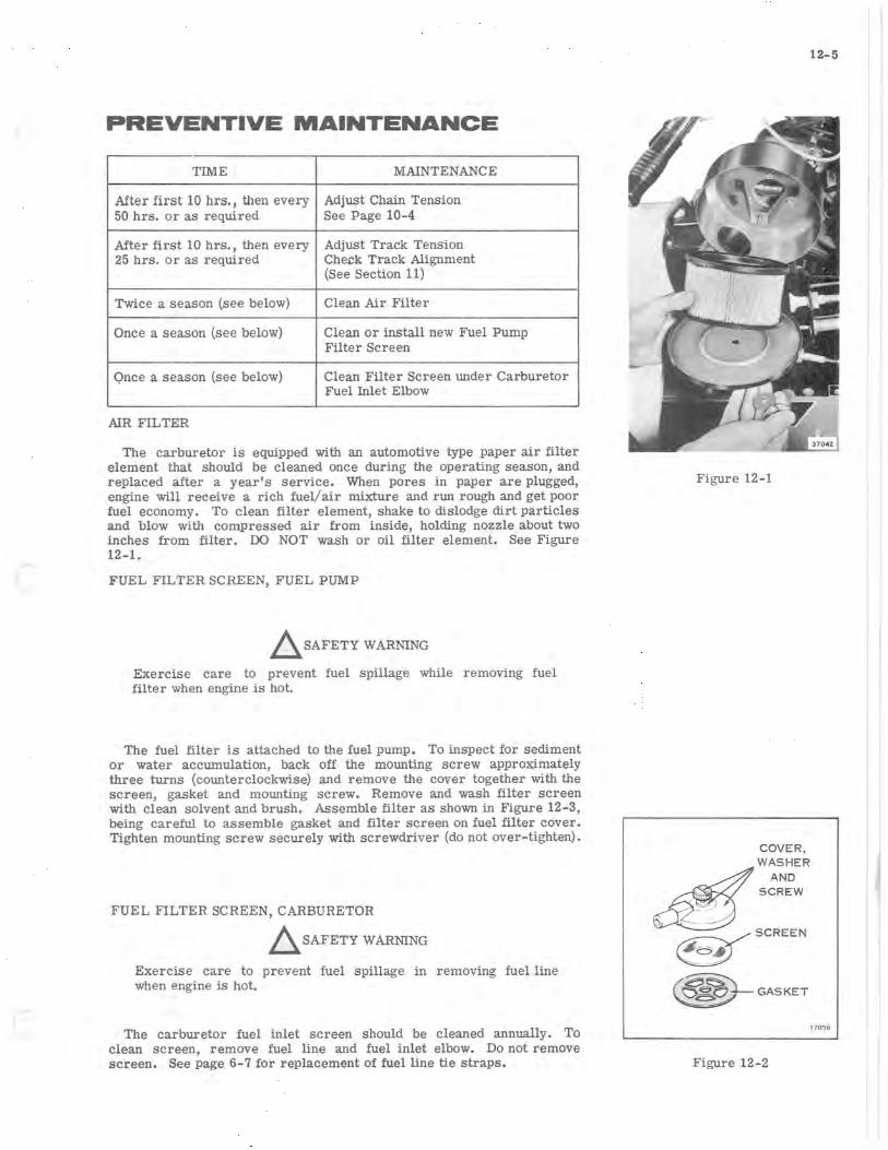
PREVENTIVE MAINTENANCE
TIME MAINTENANCE
After first 10 hrs., then every Adjust Chain Tension 50 hrs. or as required See Page 10-4
After first 10 hrs., then every Adjust Track Tension 25 hrs. or as required Check Track Alignment
(See Section 11)
Twice a season (see below) Clean Air Filter
Once a season (see below) Clean or install new Fuel Pump Filter Screen
Qnce a season (see below) Clean Filter Screen under Carburetor Fuel Inlet Elbow
AIR FILTER
The carburetor is equipped with an automotive type paper air filter element that should be cleaned once during the operating season, and replaced after a year's service. When pores in paper are plugged, engine will receive a rich fuel/air mixture and run rough and get poor fuel economy. To clean filter element, shake to dislodge dirt particles and blow with compressed air from inSide, holding nozzle about two inches from filter. 00 NOT wash or oil filter element. See Figure 12-1.
FUEL FILTER SCREEN, FUEL PUMP
~ SAFETY WARNING
Exercise care to prevent fuel spillage while removing fuel filter when engine is hot.
The fuel filter is attached to the fuel pump. To inspect for sediment or water accumulation, back off the mounting screw approximately three turns (counterclockwise) and remove the cover together with the screen, gasket and mounting screw. Remove and wash filter screen with clean solvent and brush. Assemble filter as shown in Figure 12-3, being careful to assemble gasket and filter screen on fuel filter cover. Tighten mounting screw securely with screwdriver (do not over-tighten).
FUEL FILTER SCREEN, CARBURETOR
~ SAFETY WARNING
Exercise care to prevent fuel spillage in removing fuel line when engine is hot.
The carburetor fuel inlet screen should be cleaned annually. To clean screen, remove fuel line and fuel inlet elbow. Do not remove screen. See page 6-7 for replacement of fuel line tie straps.
12-5
Figure 12-1
COVER.
~W:~~ER ~ SCREW
:\ ~SCREEN
~ ~ GASKET
17056
Figure 12-2
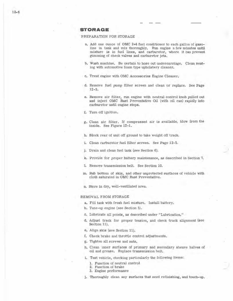
12-6
STORAGE
PREP ARATION FOR STORAGE
a. Add one ounce of OMC 2+4 fuel conditioner to each gallon of gasoline in tank and mix thoroughly. Run engine a few minutes until mixture is in fuel lines, and carburetor, where it can prevent gumming of check valves and carburetor jets.
b. Wash machine. Be certain to hose out undercarriage. Clean seating with automotive foam type upholstery cleaner.
c. Treat engine with OMC Accessor ies Engine Cleaner.
d. Remove fuel pump filter screen and clean or replace. See Page 12 - 5.
e. Remove air filter, run engine with neutral control knob pulled out and inject OMC Rust Preventative Oil (with oil can) rapidly into carburetor until engine stops.
f. Turn off ignition.
g. Clean air filter. If compressed air is aVailable, blow from the inside. See Figure 12 - 1.
h. Block rear of unit off ground to take weight off track.
i. Clean carburetor fuel filter screen. See Page 12-5.
j. Drain and clean fuel tank (see Section 6).
k. Provide for proper battery maintenance, as described in Section 7.
1. Remove transmission belt. See Section 10.
m. Rub bottom of skiS, and other unprotected surfaces of vehicle with cloth saturated in OMC Rust Preventative.
n. Store in dry, well-ventilated area.
REMOVAL FROM STORAGE
a. Fill tank with fresh fuel mixture. Install battery.
b. Tune-up engine (see Section 5).
c. Lubricate all pOints, as described under "Lubrication."
d. Adjust track for proper tension, and check track alignment (see Section 11).
e. Align skis (see Section 11).
f. Check brake and throttle control adjustments.
g. Tighten all screws and nuts.
h. Clean inner surfaces of primary and secondary sheave halves of oil and grease. Replace transmission belt.
i. Test vehicle, checking particularly the following items:
1. Function of neutral control 2. Function of brake 3. Engine performance
j. Thoroughly clean any surfaces that need refinishing, and touch-up.