Embed Size (px)
Citation preview
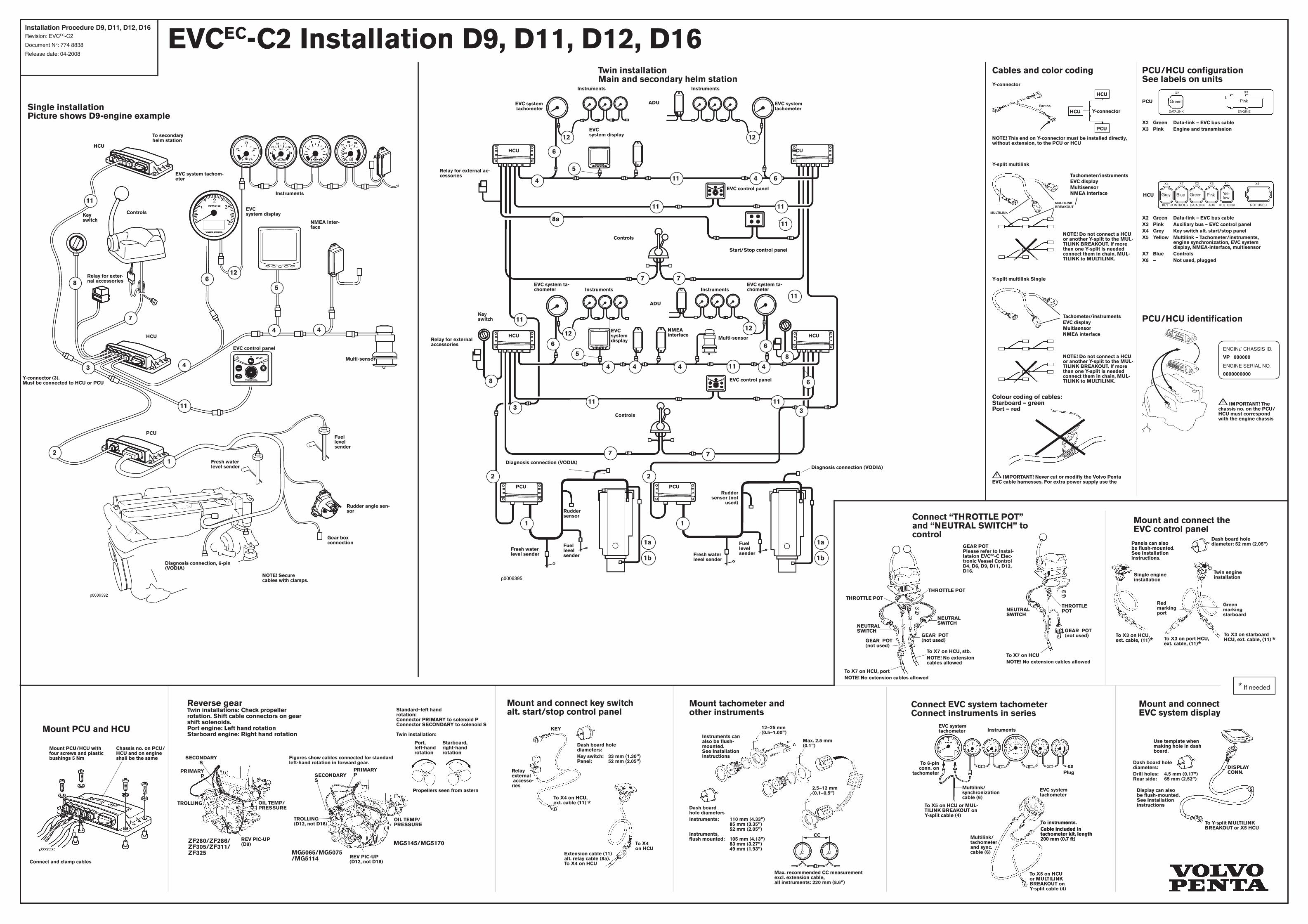
EVCEC-C2 Installation D9, D11, D12, D16
Mount and connect the EVC control panel
Single engine installation
Panels can also be flush-mounted. See Installation instructions.
Dash board hole diameter: 52 mm (2.05”)
Twin engine installation
Green marking starboard
Red marking port
To X3 on HCU, ext. cable, (11) To X3 on port HCU,
ext. cable, (11)
To X3 on starboard HCU, ext. cable, (11)
PCU/HCU configuration See labels on units
HCU
PCU
MULTILINKDATALINK AUXKEY
Yel- low
PinkGray Blue
CONTROLS NOT USED
X4 X7 X2 X3 X5 X8
Green Pink
DATALINK ENGINE
X2 X3
Mount PCU and HCU
To X4 on HCU
Mount and connect key switch alt. start/stop control panel
Extension cable (11) alt. relay cable (8a). To X4 on HCU
To X4 on HCU, ext. cable (11)
KEY
Dash board hole diameters: Key switch: 33 mm (1.30”) Panel: 52 mm (2.05”)
Relay external accesso-ries
12–25 mm (0.5–1.00”)
2.5–12 mm (0.1–0.5”)
Max. 2.5 mm (0.1”)
Instruments can also be flush-mounted. See Installation instructions
Mount tachometer and other instruments
Dash board hole diametersInstruments: 110 mm (4.33”) 85 mm (3.35”) 52 mm (2.05”) Instruments, flush mounted: 105 mm (4.13”) 83 mm (3.27”) 49 mm (1.93”)
Max. recommended CC measurement excl. extension cable, all instruments: 220 mm (8.6”)
CC
Connect EVC system tachometer Connect instruments in series
Plug
To 6-pin conn. on
tachometer
EVC system tachometer
To X5 on HCU or MUL-TILINK BREAKOUT on Y-split cable (4)
Multilink/ synchronization cable (6)
Multilink/ tachometer and sync. cable (6)
To X5 on HCU or MULTILINK BREAKOUT on Y-split cable (4)
To instruments.Cable included in tachometer kit, length 200 mm (0.7 ft)
Instruments
EVC system tachometer
Mount and connect EVC system display
DISPLAY CONN.
Use template when making hole in dash board.
Dash board hole diameters: Drill holes: 4.5 mm (0.17”) Rear side: 65 mm (2.52”)
Display can also be flush-mounted. See Installation instructions
To Y-split MULTILINK BREAKOUT or X5 HCU
Single installationPicture shows D9-engine example
Twin installationMain and secondary helm station
IMPORTANT! Never cut or modifiy the Volvo Penta EVC cable harnesses. For extra power supply use the
HCU
HCU
PCU
NOTE! This end on Y-connector must be installed directly, without extension, to the PCU or HCU
Y-connector
Y-connector
Part no.
Colour coding of cables:Starboard – green Port – red
Cables and color coding
PCU/HCU identification
ENGINE CHASSIS ID.
VP 000000 ENGINE SERIAL NO.
0000000000
IMPORTANT! The chassis no. on the PCU/HCU must correspond with the engine chassis
Standard–left hand rotation: Connector PRIMARY to solenoid P Connector SECONDARY to solenoid S Twin installation:
Starboard, right-hand rotation
Port, left-hand rotation
Propellers seen from astern
Reverse gear Twin installations: Check propeller rotation. Shift cable connectors on gear shift solenoids. Port engine: Left hand rotation Starboard engine: Right hand rotation
Figures show cables connected for standard left-hand rotation in forward gear.
SECONDARY S
PRIMARY P
PRIMARY P
OIL TEMP/PRESSURE
SECONDARY S
ZF280/ZF286/ZF305/ZF311/ZF325 MG5065/MG5075
/MG5114
TROLLING
REV PIC-UP (D9)
OIL TEMP/PRESSURE
REV PIC-UP (D12, not D16)
TROLLING (D12, not D16)
MG5145/MG5170
To X7 on HCU NOTE! No extension cables allowed
Connect “THROTTLE POT” and “NEUTRAL SWITCH” to control
GEAR POT Please refer to Instal-lataion EVCEC-C Elec-tronic Vessel Control D4, D6, D9, D11, D12, D16.
THROTTLE POT
To X7 on HCU, portNOTE! No extension cables allowed
THROTTLE POT
NEUTRAL SWITCH
NEUTRAL SWITCH
To X7 on HCU, stb.NOTE! No extension cables allowed
GEAR POT (not used)GEAR POT
(not used)
THROTTLE POTNEUTRAL
SWITCH
GEAR POT (not used)
To instruments.Cable included in tachometer kit, length 200 mm (0.7 ft)
X2 Green Data-link – EVC bus cableX3 Pink Engine and transmission
X2 Green Data-link – EVC bus cableX3 Pink Auxiliary bus – EVC control panelX4 Grey Key switch alt. start/stop panelX5 Yellow Multilink – Tachometer/instruments, engine synchronization, EVC system display, NMEA-interface, multisensorX7 Blue ControlsX8 — Not used, plugged
Green
5
Y-split multilink
MULTILINK BREAKOUT
MULTILINK
NOTE! Do not connect a HCU or another Y-split to the MUL-TILINK BREAKOUT. If more than one Y-split is needed connect them in chain, MUL-TILINK to MULTILINK.
Tachometer/instruments EVC display Multisensor NMEA interface
PCU
HCU
ADU
Y-connector (3). Must be connected to HCU or PCU
NOTE! Secure cables with clamps.
HCU
Key switch
To secondary helm station
Rudder angle sen-sor
Relay for exter-nal accessories
Instruments
Fuel level sender
Fresh water level sender
Multi-sensor
NMEA inter-face
EVC system display
EVC control panel
EVC system tachom-eter
Diagnosis connection, 6-pin (VODIA)
Controls
11
8
7
3 4
4 4
126
5
11
21
Y-split multilink Single
NOTE! Do not connect a HCU or another Y-split to the MUL-TILINK BREAKOUT. If more than one Y-split is needed connect them in chain, MUL-TILINK to MULTILINK.
Tachometer/instruments EVC display Multisensor NMEA interface
5
4
7
Instruments Instruments
ADU
InstrumentsInstruments
EVC system display
EVC system tachometer
EVC system tachometer
EVC system ta-chometer
EVC system display
Relay for external ac-cessories
Relay for external accessories
Key switch
EVC control panel
EVC control panel
Start/Stop control panel
Fuel level sender
Fresh water level sender
Fuel level senderFresh water
level sender
Diagnosis connection (VODIA)
Multi-sensor
NMEA interface
ADU
HCU
Controls
Controls
PCU
411
6
6
Diagnosis connection (VODIA)
Rudder sensor
8
8a
1212
1a
Rudder sensor (not
used)
11 11
11
11
11
6
12
5
7
4 4 4 4
6
6
12
11
11
8
3 311
7 7
2 2
1 1
1b
1a
1b
HCU
HCU HCU
PCU
EVC system ta-chometer
Gear box connection
Installation Procedure D9, D11, D12, D16Revision: EVCEC-C2
Document N°: 774 8838
Release date: 04-2008
* If needed
* * *
*
Chassis no. on PCU/HCU and on engine shall be the same
Mount PCU/HCU with four screws and plastic bushings 5 Nm
Connect and clamp cables
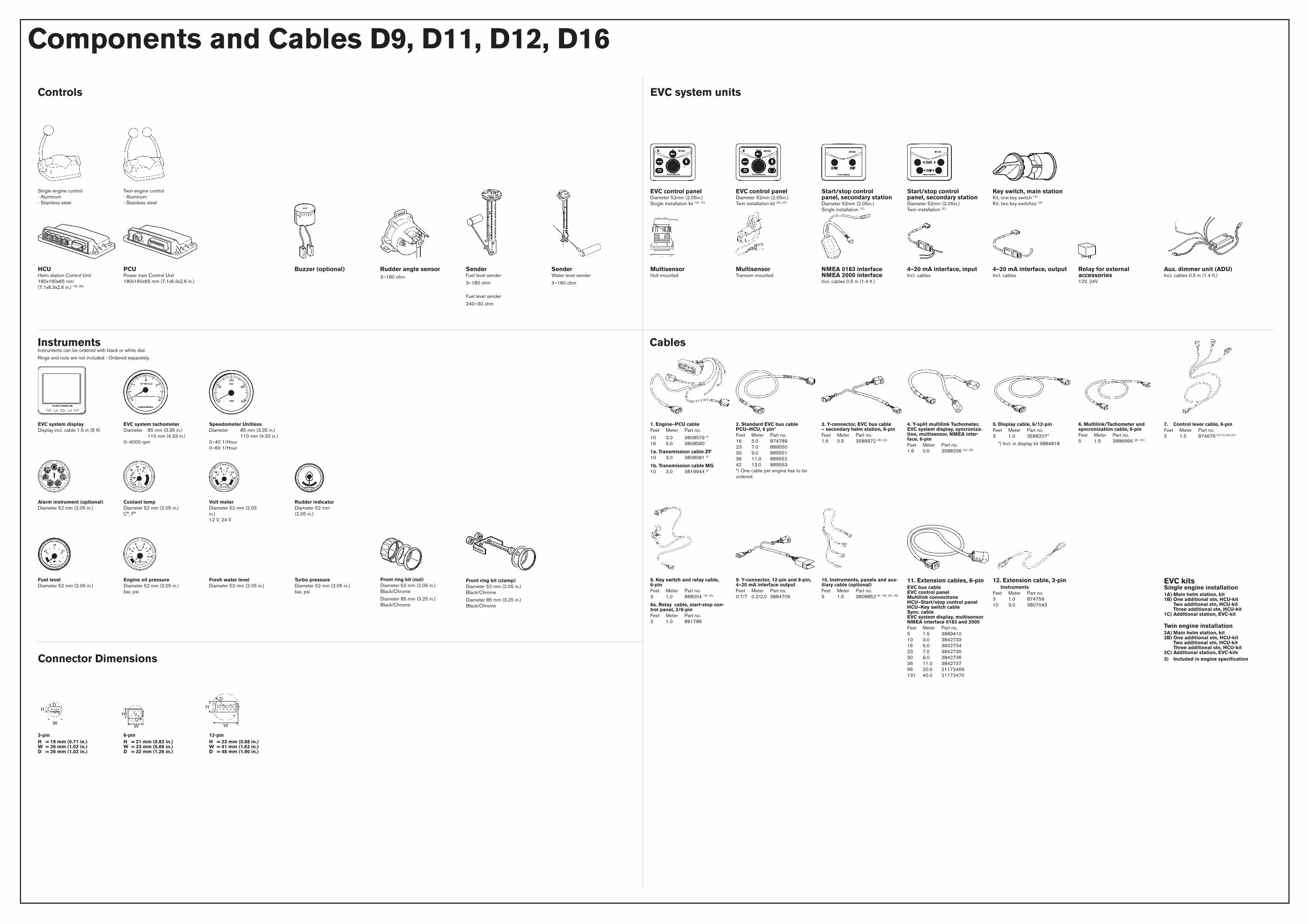
Components and Cables D9, D11, D12, D16
Controls
Single engine control - Aluminum - Stainless steel
PCU Power train Control Unit 180x160x65 mm (7.1x6.3x2.6 in.)
SenderFuel level sender
3–180 ohm
Fuel level sender
240–30 ohm
Fresh water levelDiameter 52 mm (2.05 in.)
EVC kitsSingle engine installation1A) Main helm station, kit 1B) One additional stn, HCU-kit Two additional stn, HCU-kit Three additional stn, HCU-kit 1C) Additional station, EVC-kit Twin engine installation 2A) Main helm station, kit 2B) One additional stn, HCU-kit Two additional stn, HCU-kit Three additional stn, HCU-kit 2C) Additional station, EVC-kitv3) Included in engine specification
2. Standard EVC bus cable PCU–HCU, 6 pin*Feet Meter Part no. 16 5.0 874789 23 7.0 889550 30 9.0 889551 36 11.0 889552 42 13.0 889553 *) One cable per engine has to be ordered.
Relay for external accessories12V, 24V
EVC control panelDiameter 52mm (2.05in.) Single installation kit 1A), 1C)
3-pinH = 18 mm (0.71 in.) W = 26 mm (1.02 in.) D = 26 mm (1.02 in.)
W
H
D
H
WD
H
W
D
EVC system units
InstrumentsInstruments can be ordered with black or white dial.
Rings and nuts are not included - Ordered separately.
Cables
Connector Dimensions
EVC system tachometerDiameter 85 mm (3.35 in.) 110 mm (4.33 in.) 0–4000 rpm
Coolant tempDiameter 52 mm (2.05 in.) C°, F°
Speedometer UnitlessDiameter 85 mm (3.35 in.) 110 mm (4.33 in.) 0–40 1/Hour 0–60 1/Hour
Alarm instrument (optional)Diameter 52 mm (2.05 in.)
Volt meterDiameter 52 mm (2.05 in.) 12 V, 24 V
Rudder indicatorDiameter 52 mm (2.05 in.)
Front ring kit (nut) Diameter 52 mm (2.05 in.) Black/Chrome
Diameter 85 mm (3.25 in.) Black/Chrome
Front ring kit (clamp) Diameter 52 mm (2.05 in.) Black/Chrome
Diameter 85 mm (3.25 in.) Black/Chrome
Twin engine control - Aluminum - Stainless steel
EVC system displayDisplay incl. cable 1.5 m (5 ft)
Fuel levelDiameter 52 mm (2.05 in.)
Engine oil pressureDiameter 52 mm (2.05 in.) bar, psi
Turbo pressureDiameter 52 mm (2.05 in.) bar, psi
HCU Helm station Control Unit 180x160x65 mm (7.1x6.3x2.6 in.) 1B), 2B),
1. Engine–PCU cableFeet Meter Part no.
10 3.0 3808579 3) 16 5.0 3808580
1a. Transmission cable ZF 10 3.0 3808581 3)
1b. Transmission cable MG 10 3.0 3819944 3)
Buzzer (optional) Rudder angle sensor3–180 ohm
Key switch, main stationKit, one key switch 1A) Kit, two key switches 2A)
EVC control panelDiameter 52mm (2.05in.) Twin installation kit 2A), 2C)
Start/stop control panel, secondary stationDiameter 52mm (2.05in.) Single installation 1C)
Start/stop control panel, secondary stationDiameter 52mm (2.05in.) Twin installation 2C)
MultisensorHull mounted
Multisensor Transom mounted
NMEA 0183 interface NMEA 2000 interfaceIncl. cables 0.5 m (1.4 ft.)
4–20 mA interface, inputIncl. cables
4–20 mA interface, outputIncl. cables
Aux. dimmer unit (ADU)Incl. cables 0.5 m (1.4 ft.)
3. Y-connector, EVC bus cable – secondary helm station, 6-pinFeet Meter Part no. 1.6 0.5 3588972 1B), 2C)
4. Y-split multilink Tachometer, EVC system display, syncroniza-tion, multisensor, NMEA inter-face, 6-pinFeet Meter Part no. 1.6 0.5 3588206 2A), 2B)
5. Display cable, 6/12-pinFeet Meter Part no. 3 1.0 3588207*
*) Incl. in display kit 3884818
6. Multilink/Tachometer and syncronization cable, 6-pinFeet Meter Part no. 5 1.5 3886666 2A), 2C)
7. Control lever cable, 6-pinFeet Meter Part no. 5 1.5 8746761A),1C),2A),2C)
8. Key switch and relay cable, 6-pinFeet Meter Part no. 3 1.0 888004 1A), 2A)
8a. Relay cable, start-stop con-trol panel, 2/6-pinFeet Meter Part no. 3 1.0 881786
9. Y-connector, 12-pin and 8-pin, 4–20 mA interface outputFeet Meter Part no. 0.7/7 0.2/2.0 3884709
10. Instruments, panels and aux-iliary cable (optional)Feet Meter Part no. 5 1.5 38088521A), 1B), 2A), 2B)
11. Extension cables, 6-pinEVC bus cable EVC control panel Multilink connections HCU–Start/stop control panel HCU–Key switch cable Sync. cable EVC system display, multisensor NMEA interface 0183 and 2000Feet Meter Part no. 5 1.5 3889410 10 3.0 3842733 16 5.0 3842734 23 7.0 3842735 30 9.0 3842736 36 11.0 3842737 66 20.0 21172469 131 40.0 21172470
12. Extension cable, 3-pin InstrumentsFeet Meter Part no. 3 1.0 874759 10 3.0 3807043
6-pinH = 21 mm (0.82 in.) W = 23 mm (0.88 in.) D = 32 mm (1.26 in.)
12-pinH = 23 mm (0.88 in.) W = 41 mm (1.62 in.) D = 48 mm (1.90 in.)
SenderWater level sender
3–180 ohm
SPEED
1/HOUR