Embed Size (px)
Citation preview
EVAL BOARD USER’S MANUALwww.onsemi.com
© Semiconductor Components Industries, LLC, 2018
February, 2022 − Rev. 31 Publication Order Number:
EVBUM2581/D
Ezairo� 7160 SL Hybrid Demonstrator BoardUser's Manual
EVBUM2581/D
BOARD DESIGN & OVERVIEW
PurposeThis manual provides information on the configuration
and use of the Ezairo 7160 SL Hybrid Demonstrator Board.The demonstrator board is designed to be used with the
Ezairo Preconfigured Suite (Pre Suite), or the Ezairo 7100Open−Programmable Evaluation and Development Kit(EDK) to develop wireless−enabled hearing aids based onthe Ezairo 7160 SL.
Manual OrganizationThe Hybrid Demonstrator Board Manual contains the
following chapters and appendices:• Chapter 1: Introduction describes the purpose of this
manual, describes the target reader, explains how thebook is organized, and provides a list of suggested readingfor more information.
• Chapter 2: Overview provides an overview of theDemonstrator Board described in this manual.
• Chapter 3: Configuration provides the details of theDemonstrator Board. The chapter contains informationon the following topics:♦ Demonstrator Board Setup♦ Demonstrator Board Design♦ Power Supply♦ Level Translators♦ LED Circuitry♦ Promira/CAA Debug Port♦ SWJ−DP Debug Port♦ Digital Input/Output (DIO)♦ Test Points
Further ReadingFor any technical information not covered in this manual,
refer to the following documents:• Promira™ Serial Platform Quick Start Guide, available at
totalphase.com• Communication Accelerator Adaptor Manual, which is
installed with the Communication Accelerator Adaptor(CAA) software
• Integrated Development Environment User’s Guide
• Introduction to Ezairo 7100 Programming
• CFX DSP Architecture Manual
• Hardware Reference Manual for Ezairo 7100
• HEAR Configurable Accelerator Reference Manual for
Ezairo 7100
• Firmware Reference Manual for Ezairo 7100
• SK4 ELF Toolchain Reference for Ezairo 7100
• Ezairo 7160 SL Datasheet
• Ezairo Sound Designer Software User Manual
BOARD DESIGN & OVERVIEW
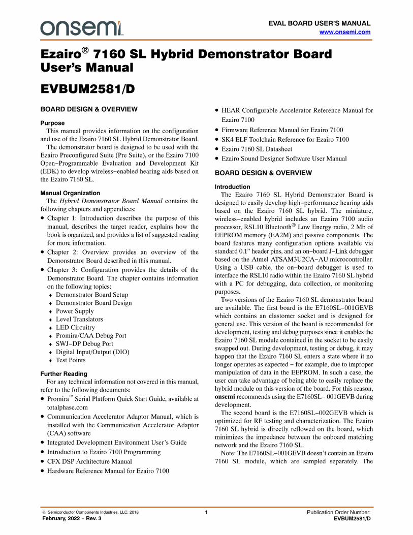
IntroductionThe Ezairo 7160 SL Hybrid Demonstrator Board is
designed to easily develop high−performance hearing aidsbased on the Ezairo 7160 SL hybrid. The miniature,wireless−enabled hybrid includes an Ezairo 7100 audioprocessor, RSL10 Bluetooth® Low Energy radio, 2 Mb ofEEPROM memory (EA2M) and passive components. Theboard features many configuration options available viastandard 0.1” header pins, and an on−board J−Link debuggerbased on the Atmel ATSAM3U2CA−AU microcontroller.Using a USB cable, the on−board debugger is used tointerface the RSL10 radio within the Ezairo 7160 SL hybridwith a PC for debugging, data collection, or monitoringpurposes.
Two versions of the Ezairo 7160 SL demonstrator boardare available. The first board is the E7160SL−001GEVBwhich contains an elastomer socket and is designed forgeneral use. This version of the board is recommended fordevelopment, testing and debug purposes since it enables theEzairo 7160 SL module contained in the socket to be easilyswapped out. During development, testing or debug, it mayhappen that the Ezairo 7160 SL enters a state where it nolonger operates as expected − for example, due to impropermanipulation of data in the EEPROM. In such a case, theuser can take advantage of being able to easily replace thehybrid module on this version of the board. For this reason,onsemi recommends using the E7160SL− 001GEVB duringdevelopment.
The second board is the E7160SL−002GEVB which isoptimized for RF testing and characterization. The Ezairo7160 SL hybrid is directly reflowed on the board, whichminimizes the impedance between the onboard matchingnetwork and the Ezairo 7160 SL.
Note: The E7160SL−001GEVB doesn’t contain an Ezairo7160 SL module, which are sampled separately. The
EVBUM2581/D
www.onsemi.com2
E7160SL−002GEVB contains one hybrid module solderedon the board.
The Ezairo 7160 SL demonstrator board main functionalblocks are shown in Figure 1.
Figure 1. Ezairo 7160 SL Hybrid Demonstrator Board Overview
Ezairo 7160 SL Demonstrator Board Features• On−board J−Link adaptor for debugging through a USB
connection to the PC• Alternate on−board SWJ−DP (serial−wire and/or JTAG)
interface for debugging the Arm® Cortex−M3 processor• Access to all Ezairo 7160 SL peripherals via standard 0.1”
headers• Onboard 4−bit level translator to translate the DIOs and
debug interface at low voltage to a 3.3 V JTAG debugger• 4 Push Button Switches
• On board 3.3 V Regulator
• 3 LEDs
• Test points and GND hooks for easy probing
• Battery Holder
• Current measuring header
• Elastomer socket with hybrid (E7160SL−001GEVBonly)
• Antenna matching and filtering network
CONFIGURATION
Ezairo E7160SL−001GEVB Socketed BoardThe socket used on this version of the Ezairo 7160 SL
demonstrator board is designed for easy, tool−free, use. Thefollowing are the steps required to ensure proper function ofthe socket.
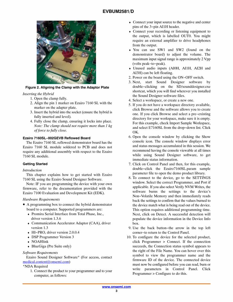
Aligning the Clamp1. Ensure that the rubber plunger sits flush with the top
of the grey adapter plate near the end of the range ofmotion of the clamp.
2. With minimal pressure, the clamp should lock intoplace.
3. Ensure that the rubber plunger lines up with thecutout in the grey adapter plate.
4. Tighten all nuts fully if adjustment was required.
EVBUM2581/D
www.onsemi.com3
Figure 2. Aligning the Clamp with the Adaptor Plate
Inserting the Hybrid1. Open the clamp fully.2. Align the pin 1 marker on Ezairo 7160 SL with the
marker on the adapter plate.3. Insert the hybrid into the socket (ensure the hybrid is
fully inserted and level).4. Fully close the clamp, ensuring it locks into place.
Note: The clamp should not require more than 1 kgof force to fully close.
Ezairo 7160SL−002GEVB Reflowed BoardThe Ezairo 7160 SL reflowed demonstrator board has the
Ezairo 7160 SL module soldered to PCB and does notrequire any additional assembly with respect to the Ezairo7160 SL module.
Getting Started
IntroductionThis chapter explains how to get started with Ezairo
7160 SL using the Ezairo Sound Designer Software.Note: IF you are programming the device with your own
firmware, refer to the documentation provided with theEzairo 7100 Evaluation and Development Kit (EDK).
Hardware Requirements• A programming box to connect the hybrid demonstrator
board to a computer. Supported programmers are:♦ Promira Serial Interface from Total Phase, Inc.,
driver version 1.3.6♦ Communication Accelerator Adaptor (CAA), driver
version 1.3♦ HI−PRO, driver version 2.0.0.4♦ DSP Programmer Version 3♦ NOAHlink♦ BlueGiga (Pre Suite only)
Software RequirementsEzairo Sound Designer Software* (For access, contact
[email protected])*NDA Required
1. Connect the product to your programmer and to yourcomputer, as follows:
♦ Connect your input source to the negative and centerpins of the 3−pin AI1H header.
♦ Connect your recording or listening equipment tothe output, which is labelled OUT0. You mightrequire an external amplifier to drive headphonesfrom the output.
♦ You can use SW1 and SW2 (found on thedemonstrator board) to adjust the volume. Themaximum input signal range is approximately 2 Vpp(volts peak−to−peak).
♦ Unused audio inputs (AI0H, AI1H, AI2H andAI3H) can be left floating.
2. Power on the board using the ON−OFF switch.3. Next, start Sound Designer software by
double−clicking on the SD/sounddesigner.exeshortcut, which you will find wherever you installedthe Sound Designer software files.
4. Select a workspace, or create a new one.5. If you do not have a workspace directory available,
click Browse and the software allows you to createone. If you click Browse and select a pre−existingdirectory for your workspace, make sure it is empty.For this example, check Import Sample Workspace,and select E7160SL from the drop−down list. ClickOK.
6. Open the console window by clicking the Showconsole icon. The console window displays errorand status messages accumulated in this session. Werecommend having the console viewable at all timeswhile using Sound Designer software, to getimmediate status information.
7. Click on Control Panel and then, for this example,double−click the Ezairo7160SL.param sampleparameter file to open the demo product library.
8. To connect to the device, go to the SETTINGSwindow. Select the correct Programmer, and Port ifapplicable. If you also select Verify NVM Writes, thesoftware burns the settings to the device’sNon−Volatile Memory and then immediately readsback the settings to confirm that the values burned tothe device match what is being read out of the device.This option requires additional programming time.Next, click on Detect. A successful detection willpopulate the device information in the Device Infobox.
9. Use the back button−the arrow in the top leftcorner−to return to the Control Panel.
10. To configure the device for the selected product,click Programmer > Connect. If the connectionsucceeds, the Connection status symbol appears tothe right of the File Name. You can hover over thissymbol to view the programmer name and thefirmware ID of the device. The connected devicemust now be configured before you can read, burn orwrite parameters in Control Panel. ClickProgrammer > Configure to do this.
EVBUM2581/D
www.onsemi.com4
11. Now you are ready to begin. See Chapter 3,“Modeler” on page 15 of the Ezairo Sound
Designer Software User Manual for your next steps in theprocess of developing a product with Sound Designersoftware.
Power SupplyThe Ezairo 7160 SL demonstrator board is split into two
distinct subsystems, the Ezairo 7160 module and an Atmelmicrocontroller which acts as an on−board J−Link debugger,to interface and control the RSL10 portion of the Ezairo7160 SL hybrid without using an external J−Link device.Therefore, there are also 2 subsystems in the power supply.One subsystem supplies power to the Ezairo 7160 SL and theother supplies power to the Atmel microcontroller, withvariations and configurations options available for each.
Ezairo 7160 SL Demonstrator Board Power SupplyEzairo 7160 SL can be powered from several sources,
including the onboard battery connector, an external powersupply connected via header pins, or from the 6−pin DINCAA connector. Shorting two pins together on thePSU_SEL header chooses which supply source to use, seeTable 1. It is also possible to separately turn off the Ezairo7160 SL using the on−off switch. This will only turn offpower to that module, not the onboard Atmelmicrocontroller. This can, for example, be used to savebattery power if using a battery as the power supply source.For Ezairo 7160 SL to be powered, the VBAT-I header mustalso be shorted. The VBAT-I header optionally providesa location to measure current consumption of Ezairo 7160SL.
Table 1. Ezairo 7160 SL POWER SUPPLY OPTIONS
PSU_SEL Power Supply Source
Short pin 1 to 2 6−Pin DIN (CAA Connector)
Short pin 3 to 4 External Bench Supply (EXT_PSU header)
Short pin 5 to 6 Battery (On board battery holder)
Table 2. VBAT SUPPLY
Pin Name Min Nom Max
VBAT 1.13 V 1.25 V 2.0 V
Atmel Microcontroller Power SupplyThe Atmel microcontroller core is powered by a 3.3 V
LDO regulator. The regulator is powered by a 5 V rail, whichis supplied either by a USB or JTAG connection. The sourcefor this 5 V rail is selected using the 5 V_SEL header. SeeTable 3. This 3.3 V power source is provided to themicrocontroller’s internal regulator, which outputs 1.8 Vthat is used to power the microcontroller. The rest of the
voltage supplies on the microcontroller, for DigitalInput/Outputs and Analog references, etc. are supplied fromthe VDD_AT_SEL header. See Table 4 for configurationoptions. Table 5 lists the range of voltage outputs possiblefor the VDBL output. Do note that the UTMI on themicrocontroller expects 3.0 V − 3.6 V. Selecting VDBL asa source will put the UTMI out of its operating range. See theEzairo 7100 Hardware Reference Manual on details forVDBL configuration.
Table 3. ATMEL MICROCONTROLLER POWERSUPPLY SELECTION
PSU_SEL Power Supply Source
Short pin 1 to 2 USB power
Short pin 2 to 3 JTAG power
Table 4. ATMEL MICROCONTROLLER DIO, AREF,UTMI POWER SUPPLY SELECTION
PSU_SEL Power Supply Source
Short pin 1 to 2 3.3 V Onboard regulator
Short pin 2 to 3 Configurable voltage output from E7160(VDBL)
Table 5. VDBL VOLTAGE CONFIGURABLE OUTPUTRANGE
Pin Name Min Nom Max
VBAT 1.8 V 2.0 V 2.1 V
CommunicationThere are a few ways of achieving communication with
the Ezairo 7160 SL demonstrator board:The micro USB connection (J2) is a J−Link onboard
adaptor that provides a SWJ−DP/UART interface fordebugging of the RSL10.
It is also possible to connect and debug RSL10 viastandard JTAG. The JTAG (J-Link header) connector iscompatible with the J−Link debugging device from Segger.
The TC2050−IDC connector (J3 header) is used toprogram the Arm Cortex−M3 processor inside the Atmelmicrocontroller, with J−Link firmware.
Communication and debugging of Ezairo 7100 can beachieved through the Promira Serial Platform fromTotalPhase through an I2C interface. The CommunicationAccelerator Adapter (CAA) is also supported. The serialinterface can be connected to the CAA or Promira throughthe 6−pin DIN connector.
For troubleshooting purposes the I2C signals can beprobed on a standard 0.1” header available, labelled I2C, thatallows connection to the SDA (pin 2) and SCL (pin�1).

EVBUM2581/D
www.onsemi.com5
Ezairo 7160 Demonstrator Board
PC
ProgrammingInterface
On−boardDebugger
Ezairo 7160 SL
RSL10
Ezairo7100
SEGGERJ−Link
Micro USB
Micro USB
Micro USB
SWJ−DP
UART
6−pin DIN
J−Link Header
J−Link Header
Figure 3. Communication Connections
Table 6. DIN CONNECTOR PIN−OUT
Pin Number Serial Interface Pin Description
1 Supply Voltage from the Serial Interface
2 System Ground
3 SCL (I2C Clock)
4 SDA (I2C data)
5 VBAT (Sense Voltage)
6 No Connect
Table 7. COMMUNICATION CONFIGURATION
Header Configuration Description
VSENSEConnects VBAT to the SENSE pin on the 6−pinDIN connector, if shorted.
CAA-GNDConnects the ground from the Promira/CAA tothe HDB ground, if shorted.
NRESETCan be used to measure the NRESET line onthe Ezairo 7100, or to reset it if shorted.
EXTCLKPin to connect an external clock source to drivethe Ezairo 7160 SL module, specifically, theEzairo 7100 audio DSP.
RSL10The RSL10 is a Bluetooth Low Energy radio which is used
within Ezairo 7160 SL relaying information from the Ezairo7100 DSP to an external device, via Bluetooth Low Energy.There is an on−board coaxial 50 � SMA connector (J1) thatcan be used for attaching a 2.4 GHz Bluetooth antenna. Thedemonstrator board also includes an RF filtering circuit onthe antenna input/output.
Level ShiftersThe Ezairo 7160 SL demonstrator board includes two
on−board level shifters. The DEBUG header is used to enabledebugging of the RSL10 via the Atmel microprocessor.
Table 8. DEBUG HEADER CONFIGURATION
Pin Configuration Configuration
Short pin 7 to 8 andshort pin 5 to 6
SWJ−DP Debugging enabled
Short pin 3 to 4 andshort pin 1 to 2
Enable serial communicationbetween RSL10 and Atmelmicrocontroller
Short pin 2 to 4 Enable serial loop back on Atmelmicrocontroller
The board also includes a second level shifter accessiblevia the LEVEL_SHIFTER header. This is made available toconnect external peripherals to Ezairo 7160 SL via theRFIO/DIO headers that operate at higher voltages. Pins 1, 3,5, 7 use the VDDO2 reference supply voltage selected via theVDDO2_SEL header. This is the supply that the E7160 andmore specifically, the RSL10 DIOs and Ezairo 7100 DIObank 2 use. An external power supply voltage can beconnected via the EXT_VDDO2 header. This voltage thencan be used to supply VDDO2, using the VDDO2_SELheader, negating the need for the level shifter, if the voltageconnected is safe for the Ezairo 7160 SL hybrid. Otherwise,if VDDO2 and EXT_VDDO2 differ, EXT_VDDO2 will beused as the reference for pins 2, 4, 6, 8 of the level shifter.
EVBUM2581/D
www.onsemi.com6
Table 9. VDDO2 HEADER CONFIGURATION
Pins VDDO2 Source
Short pin 1 to 2 VDBL
Short pin 3 to 4 VBAT
Short pin 5 to 6 VEXT (EXT-VDDO2)
Input StageThe Ezairo 7160 SL demonstrator board provides access
to four analog audio inputs (AI0H, AI1H, AI2H, andAI3H). The ground reference for the inputs can be adjustedusing the MIC-GND header as follows:
Table 10. INPUT GROUND REFERENCE SELECTION
MIC-GND Input Ground Reference
Short pin 1 to 2 GND_MIC*
Short pin 2 to 3 AGND
*Use GND_MIC reference when input is from a microphone.For other electrical test equipment use AGND.
There is also an optional AI3−CAP header that can be usedto place a capacitance in between the AI3H input and the AI3ADC pin.
Output StageThere are two digital outputs (RCVR0, RCVR1)
available on the board through standard 0.1” header. Thedirect digital outputs are available on headers FILTEN0,FILTEN1, respectively. Separate RC filter networks areprovided to attenuate out−of band noise from the directdigital outputs when connected to high impedance audiomeasurement equipment (OUT0, OUT1). The on−boardRC filters are enabled by the FILTEN0/FILTEN1 headersas described in Table 12. To enable output, configure theRCVR−EN and RCVR−BAT headers as described inTable 11.
Table 11. OUTPUT STAGE ENABLECONFIGURATION
Header Configuration Description
RCVR−EN Enable the output drivers of the Ezairo 7160 SLusing VBAT as a source, if shorted.
RCVR−BAT Enable the output drivers of the Ezairo 7160 SLusing the voltage connected to this header as thesource, if shorted. RCVR-EN must be disconnected.
Table 12. ON−BOARD RC FILTER CONFIGURATION
Function FILTEN0/FILTEN1
Disabled open pins 1 to 2open pins 3 to 4
Enabled short pins 1 to 2short pins 3 to 4
Note: To connect receivers or loud speakers (without the RCfilter) use headers FILTEN0/FILTEN1 pins 2 and 4.
Digital Input/Output (DIO)The Ezairo 7160 SL Hybrid Demonstrator Board contains
19 digital I/O (DIO) signals available on three separate2x4 headers that provide access to a wide variety ofinterfaces (GPIO, SPI, PCM, I2C, UART, LSAD, clocks).See the table below for pin out and reference domains. Pin 1of each header has the corresponding reference domain.Pin 8 on each header is ground. Pin 6 of the RFIO header isground.
Table 13. DIO/RFIO REFERENCE DOMAINS
DIOs DIO Header Pin Header Reference Domain
20 3 DIO3 VBAT
21 5 DIO3 VBAT
22 7 DIO3 VBAT
23 2 DIO3 VBAT
24 4 DIO3 VBAT
29 6 DIO3 VBAT
4 3 DIO1 VDBL
5 5 DIO1 VDBL
6 7 DIO1 VDBL
7 2 DIO1 VDBL
8 4 DIO1 VDBL
9 6 DIO1 VDBL
RFIO0 3 RFIO1 VDDO2
RFIO1 5 RFIO1 VDDO2
RFIO2 7 RFIO1 VDDO2
RFIO3 2 RFIO1 VDDO2
RFIO12 4 RFIO1 VDDO2

EVBUM2581/D
www.onsemi.com7
The Ezairo 7160 SL demonstrator board also has threemomentary switches that can be used as momentary hardpull−downs on DIO24 (SW1), DIO29 (SW2) andRFIO1�(SW3).
SW4 can be used to reset the RSL10 radio.
Test Point HeadersBelow is a table (Table 14) containing of a list of 0.1”
headers on the board that are provided as measurement testpoints. There are also several ground hooks available on theboard as an easy way to provide a reference. They provideeasy access to RFGND, DGND, GND−BAT and GNDOD.
Table 14. OUTPUT STAGE ENABLECONFIGURATION
Header Measurement
VREG Output of the voltage regulator in the Ezairo 7160 SL
VBAT Output voltage of the connected battery / chosenvoltage source.
AOUT Analog output test point. Can be configured to outputfrom a wide range of internal signals. See RSL10Hardware Reference.
VBDL Charge−pump output. Double VREG.
VDDO2 Current VDDO2 voltage level supplied to the E7160.
Indicator LEDsThere are three indicator LEDs on board. Two are
connected to the Atmel microcontroller. A green LED isconnected to PA29 and a red LED is connected to PA28.These can be turned on by pulling these pins low on theAtmel microcontroller. These 2 LEDs are identified with thelabel D4. The third LED, D1 is a green led that can be turnedon by pulling RFIO0 from the RSL10, low.
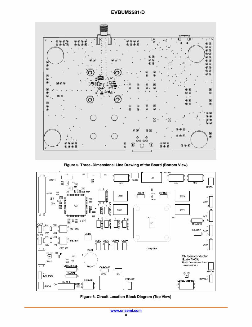
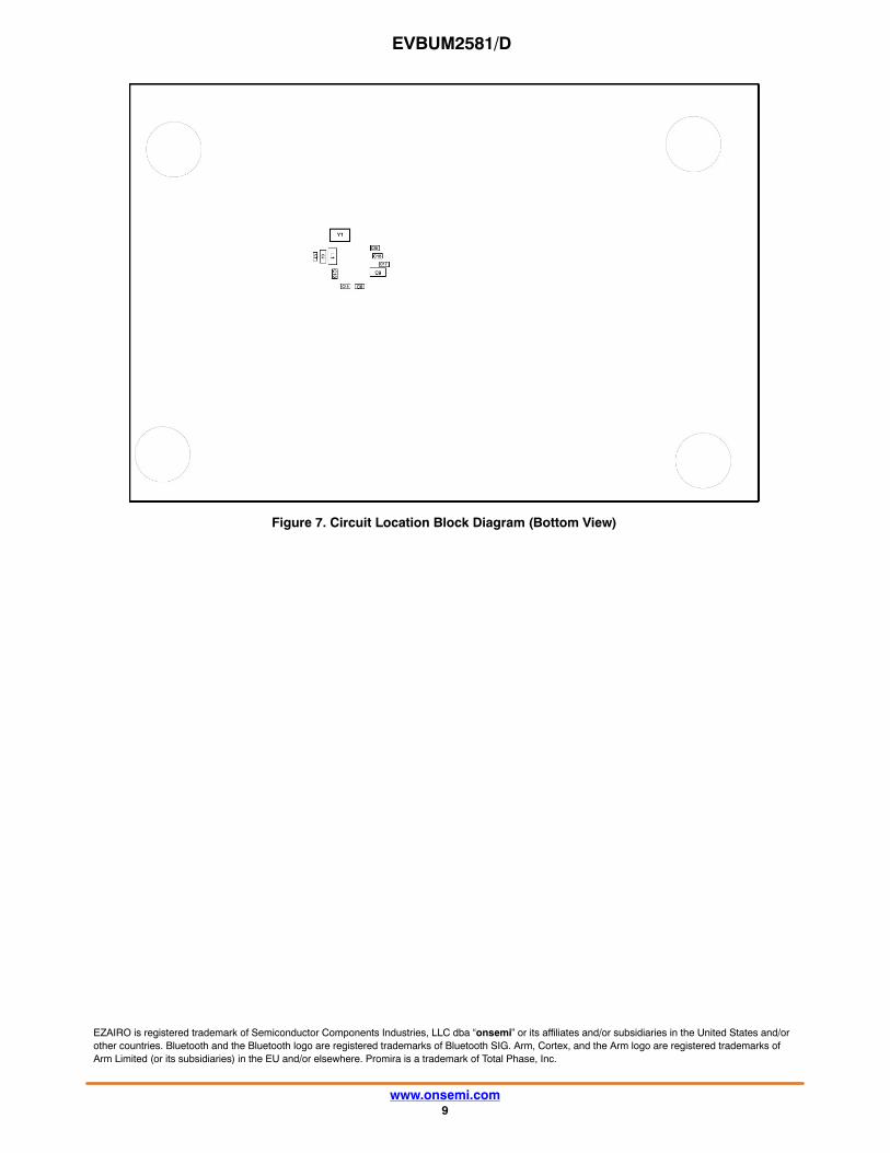
Board DesignThe following sections detail the various sub−circuits of
the Ezairo 7160 SL demonstrator board.The block diagrams in Figure 6 and Figure 7 show the
locations of the various circuit sections.Figure 4 and Figure 5 provide 3−dimensional illustrations
of the Ezairo 7160 SL demonstrator board.
Figure 4. Three−Dimensional Line Drawing of the Board (Top View)
EVBUM2581/D
www.onsemi.com8
Figure 5. Three−Dimensional Line Drawing of the Board (Bottom View)
Figure 6. Circuit Location Block Diagram (Top View)
EVBUM2581/D
www.onsemi.com9
Figure 7. Circuit Location Block Diagram (Bottom View)
EZAIRO is registered trademark of Semiconductor Components Industries, LLC dba “onsemi” or its affiliates and/or subsidiaries in the United States and/orother countries. Bluetooth and the Bluetooth logo are registered trademarks of Bluetooth SIG. Arm, Cortex, and the Arm logo are registered trademarks ofArm Limited (or its subsidiaries) in the EU and/or elsewhere. Promira is a trademark of Total Phase, Inc.

EVBUM2581/D
www.onsemi.com10
APPENDIX A
Schematic
* R1 and L1 are not required in a hearing aid design and are present for engineering and evaluation purposes.
Figure 8. Power Supply and Communication

EVBUM2581/D
www.onsemi.com11
Figure 9. DUT
* R1and L1 are not required in a hearing aid design and are present for engineering and evaluation purposes.
www.onsemi.com1
onsemi, , and other names, marks, and brands are registered and/or common law trademarks of Semiconductor Components Industries, LLC dba “onsemi” or its affiliatesand/or subsidiaries in the United States and/or other countries. onsemi owns the rights to a number of patents, trademarks, copyrights, trade secrets, and other intellectual property. Alisting of onsemi’s product/patent coverage may be accessed at www.onsemi.com/site/pdf/Patent−Marking.pdf. onsemi is an Equal Opportunity/Affirmative Action Employer. Thisliterature is subject to all applicable copyright laws and is not for resale in any manner.
The evaluation board/kit (research and development board/kit) (hereinafter the “board”) is not a finished product and is not available for sale to consumers. The board is only intendedfor research, development, demonstration and evaluation purposes and will only be used in laboratory/development areas by persons with an engineering/technical training and familiarwith the risks associated with handling electrical/mechanical components, systems and subsystems. This person assumes full responsibility/liability for proper and safe handling. Anyother use, resale or redistribution for any other purpose is strictly prohibited.
THE BOARD IS PROVIDED BY ONSEMI TO YOU “AS IS” AND WITHOUT ANY REPRESENTATIONS OR WARRANTIES WHATSOEVER. WITHOUT LIMITING THE FOREGOING,ONSEMI (AND ITS LICENSORS/SUPPLIERS) HEREBY DISCLAIMS ANY AND ALL REPRESENTATIONS AND WARRANTIES IN RELATION TO THE BOARD, ANYMODIFICATIONS, OR THIS AGREEMENT, WHETHER EXPRESS, IMPLIED, STATUTORY OR OTHERWISE, INCLUDING WITHOUT LIMITATION ANY AND ALLREPRESENTATIONS AND WARRANTIES OF MERCHANTABILITY, FITNESS FOR A PARTICULAR PURPOSE, TITLE, NON−INFRINGEMENT, AND THOSE ARISING FROM ACOURSE OF DEALING, TRADE USAGE, TRADE CUSTOM OR TRADE PRACTICE.
onsemi reserves the right to make changes without further notice to any board.
You are responsible for determining whether the board will be suitable for your intended use or application or will achieve your intended results. Prior to using or distributing any systemsthat have been evaluated, designed or tested using the board, you agree to test and validate your design to confirm the functionality for your application. Any technical, applications ordesign information or advice, quality characterization, reliability data or other services provided by onsemi shall not constitute any representation or warranty by onsemi, and no additionalobligations or liabilities shall arise from onsemi having provided such information or services.
onsemi products including the boards are not designed, intended, or authorized for use in life support systems, or any FDA Class 3 medical devices or medical devices with a similaror equivalent classification in a foreign jurisdiction, or any devices intended for implantation in the human body. You agree to indemnify, defend and hold harmless onsemi, its directors,officers, employees, representatives, agents, subsidiaries, affiliates, distributors, and assigns, against any and all liabilities, losses, costs, damages, judgments, and expenses, arisingout of any claim, demand, investigation, lawsuit, regulatory action or cause of action arising out of or associated with any unauthorized use, even if such claim alleges that onsemi wasnegligent regarding the design or manufacture of any products and/or the board.
This evaluation board/kit does not fall within the scope of the European Union directives regarding electromagnetic compatibility, restricted substances (RoHS), recycling (WEEE), FCC,CE or UL, and may not meet the technical requirements of these or other related directives.
FCC WARNING – This evaluation board/kit is intended for use for engineering development, demonstration, or evaluation purposes only and is not considered by onsemi to be a finishedend product fit for general consumer use. It may generate, use, or radiate radio frequency energy and has not been tested for compliance with the limits of computing devices pursuantto part 15 of FCC rules, which are designed to provide reasonable protection against radio frequency interference. Operation of this equipment may cause interference with radiocommunications, in which case the user shall be responsible, at its expense, to take whatever measures may be required to correct this interference.
onsemi does not convey any license under its patent rights nor the rights of others.
LIMITATIONS OF LIABILITY: onsemi shall not be liable for any special, consequential, incidental, indirect or punitive damages, including, but not limited to the costs of requalification,delay, loss of profits or goodwill, arising out of or in connection with the board, even if onsemi is advised of the possibility of such damages. In no event shall onsemi’s aggregate liabilityfrom any obligation arising out of or in connection with the board, under any theory of liability, exceed the purchase price paid for the board, if any.
The board is provided to you subject to the license and other terms per onsemi’s standard terms and conditions of sale. For more information and documentation, please visitwww.onsemi.com.
PUBLICATION ORDERING INFORMATIONTECHNICAL SUPPORTNorth American Technical Support:Voice Mail: 1 800−282−9855 Toll Free USA/CanadaPhone: 011 421 33 790 2910
LITERATURE FULFILLMENT:Email Requests to: [email protected]
onsemi Website: www.onsemi.com
Europe, Middle East and Africa Technical Support:Phone: 00421 33 790 2910For additional information, please contact your local Sales Representative
◊


![17.06 - Technische Universität München1]:accessed 27th January 2016) ... My Joghurt–accepted Industrie4.0 demonstrator Demonstrator:](https://img.pdfslide.us/doc/110x75/5ab574077f8b9ab7638cc5ad/1706-technische-universitt-mnchen-1-accessed-27th-january-2016-my-joghurtaccepted.jpg)