Embed Size (px)
Citation preview
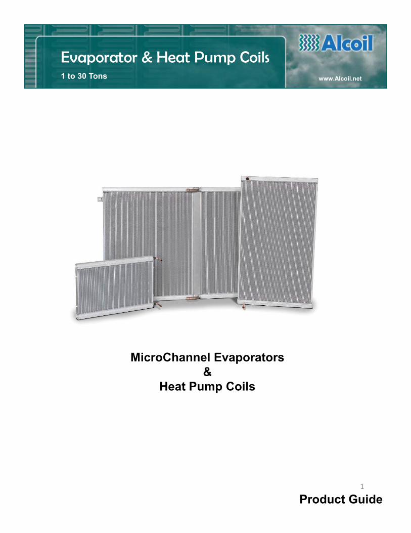
High PerformanceMicroChannel Evaporator
and Heat Pump Coil(s)
Product Guide
Evaporator & Heat Pump Coils1 to 30 Tons www.Alcoil.net
MicroChannel Evaporators&
Heat Pump Coils
1
2
When
Refrigeration Experience,
Advanced Technology
&
Innovation
Combine.
Page
Key Product Features 4MicroChannel Advantages 5How Does It Work? 6
Product Models3 Configurations 7E & HP Series 82E & 2 HP Series 102RE (Two Row) 12
Mounting 14
Application Tips 15
Coatings 20
AlcoilSELECT Software 21
Terms & Conditions 25
Contents
3
3
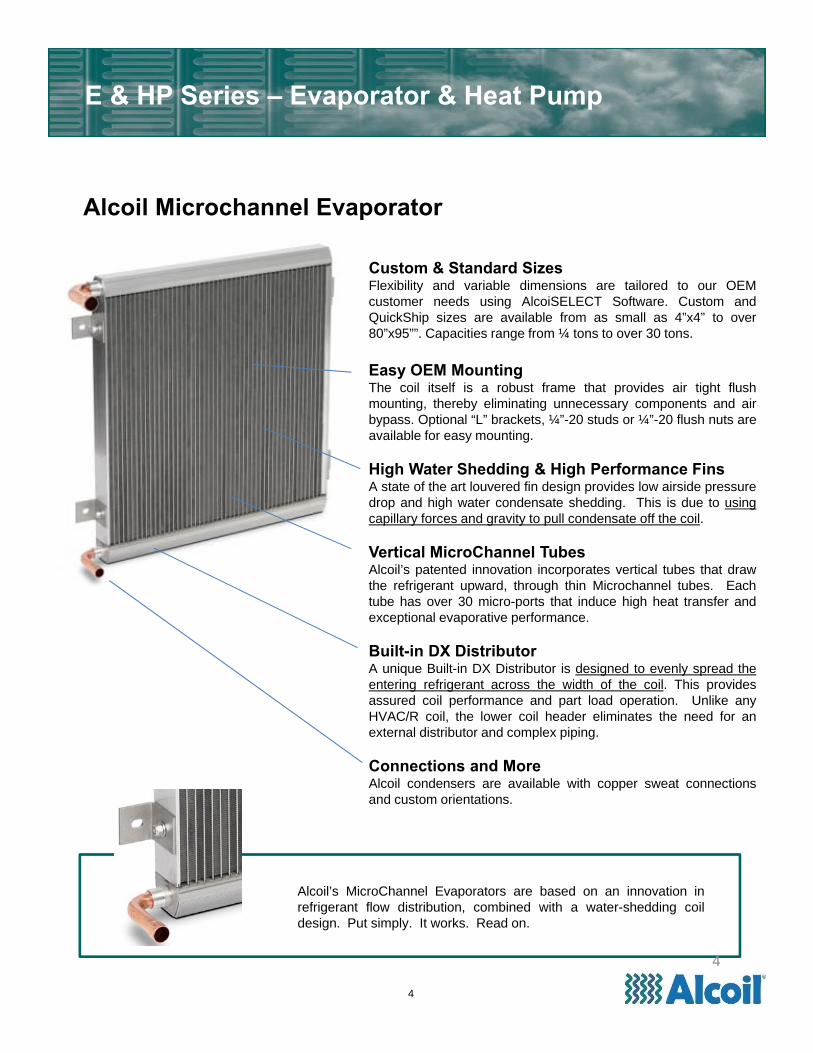
Alcoil Microchannel Evaporator
Alcoil’s MicroChannel Evaporators are based on an innovation inrefrigerant flow distribution, combined with a water-shedding coildesign. Put simply. It works. Read on.
E & HP Series – Evaporator & Heat Pump
Custom & Standard SizesFlexibility and variable dimensions are tailored to our OEMcustomer needs using AlcoiSELECT Software. Custom andQuickShip sizes are available from as small as 4”x4” to over80”x95””. Capacities range from ¼ tons to over 30 tons.
Easy OEM MountingThe coil itself is a robust frame that provides air tight flushmounting, thereby eliminating unnecessary components and airbypass. Optional “L” brackets, ¼”-20 studs or ¼”-20 flush nuts areavailable for easy mounting.
High Water Shedding & High Performance FinsA state of the art louvered fin design provides low airside pressuredrop and high water condensate shedding. This is due to usingcapillary forces and gravity to pull condensate off the coil.
Vertical MicroChannel TubesAlcoil’s patented innovation incorporates vertical tubes that drawthe refrigerant upward, through thin Microchannel tubes. Eachtube has over 30 micro-ports that induce high heat transfer andexceptional evaporative performance.
Built-in DX DistributorA unique Built-in DX Distributor is designed to evenly spread theentering refrigerant across the width of the coil. This providesassured coil performance and part load operation. Unlike anyHVAC/R coil, the lower coil header eliminates the need for anexternal distributor and complex piping.
Connections and MoreAlcoil condensers are available with copper sweat connectionsand custom orientations.
4
4
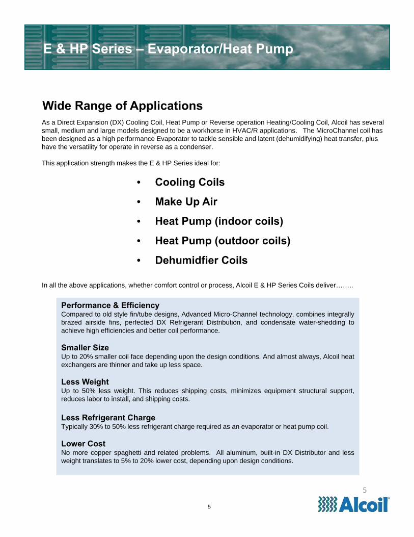
Wide Range of Applications
E & HP Series – Evaporator/Heat Pump
• Cooling Coils
• Make Up Air
• Heat Pump (indoor coils)
• Heat Pump (outdoor coils)
• Dehumidfier Coils
As a Direct Expansion (DX) Cooling Coil, Heat Pump or Reverse operation Heating/Cooling Coil, Alcoil has several small, medium and large models designed to be a workhorse in HVAC/R applications. The MicroChannel coil has been designed as a high performance Evaporator to tackle sensible and latent (dehumidifying) heat transfer, plus have the versatility for operate in reverse as a condenser.
This application strength makes the E & HP Series ideal for:
In all the above applications, whether comfort control or process, Alcoil E & HP Series Coils deliver……..
Performance & EfficiencyCompared to old style fin/tube designs, Advanced Micro-Channel technology, combines integrallybrazed airside fins, perfected DX Refrigerant Distribution, and condensate water-shedding toachieve high efficiencies and better coil performance.
Smaller SizeUp to 20% smaller coil face depending upon the design conditions. And almost always, Alcoil heatexchangers are thinner and take up less space.
Less WeightUp to 50% less weight. This reduces shipping costs, minimizes equipment structural support,reduces labor to install, and shipping costs.
Less Refrigerant ChargeTypically 30% to 50% less refrigerant charge required as an evaporator or heat pump coil.
Lower CostNo more copper spaghetti and related problems. All aluminum, built-in DX Distributor and lessweight translates to 5% to 20% lower cost, depending upon design conditions.
5
5
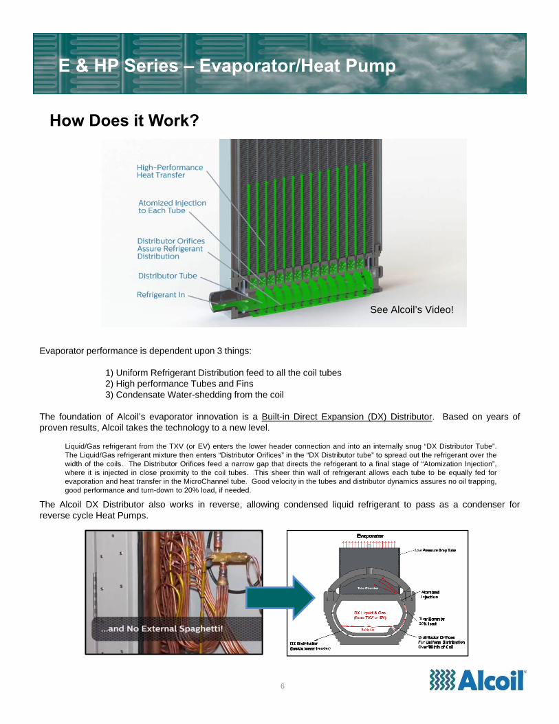
How Does it Work?
6
E & HP Series – Evaporator/Heat Pump
Evaporator performance is dependent upon 3 things:
1) Uniform Refrigerant Distribution feed to all the coil tubes2) High performance Tubes and Fins3) Condensate Water-shedding from the coil
The foundation of Alcoil’s evaporator innovation is a Built-in Direct Expansion (DX) Distributor. Based on years ofproven results, Alcoil takes the technology to a new level.
The Alcoil DX Distributor also works in reverse, allowing condensed liquid refrigerant to pass as a condenser forreverse cycle Heat Pumps.
Liquid/Gas refrigerant from the TXV (or EV) enters the lower header connection and into an internally snug “DX Distributor Tube”.The Liquid/Gas refrigerant mixture then enters “Distributor Orifices” in the “DX Distributor tube” to spread out the refrigerant over thewidth of the coils. The Distributor Orifices feed a narrow gap that directs the refrigerant to a final stage of “Atomization Injection”,where it is injected in close proximity to the coil tubes. This sheer thin wall of refrigerant allows each tube to be equally fed forevaporation and heat transfer in the MicroChannel tube. Good velocity in the tubes and distributor dynamics assures no oil trapping,good performance and turn-down to 20% load, if needed.
See Alcoil’s Video!
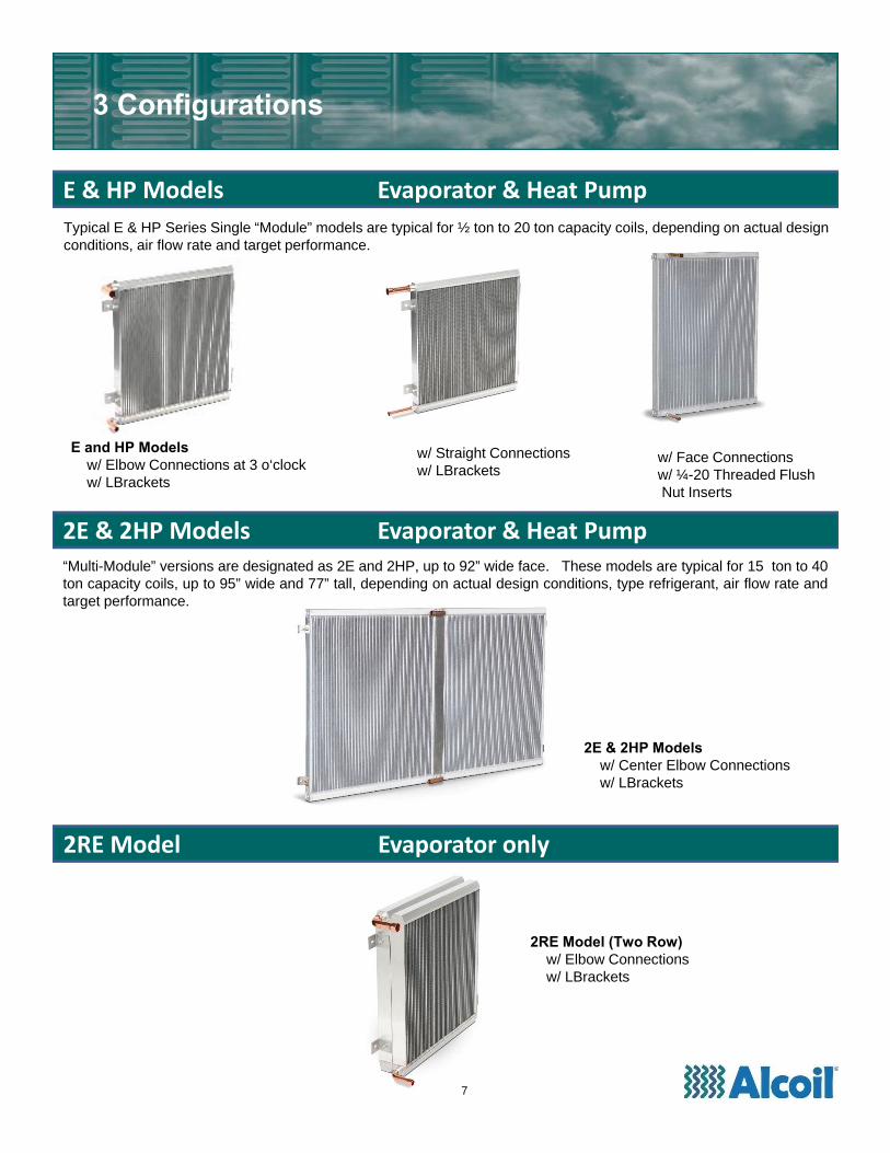
E and HP Modelsw/ Elbow Connections at 3 o‘clockw/ LBrackets
w/ Straight Connectionsw/ LBrackets
w/ Face Connectionsw/ ¼-20 Threaded Flush Nut Inserts
7
2RE Model (Two Row)w/ Elbow Connections w/ LBrackets
2E & 2HP Models w/ Center Elbow Connectionsw/ LBrackets
Typical E & HP Series Single “Module” models are typical for ½ ton to 20 ton capacity coils, depending on actual design conditions, air flow rate and target performance.
“Multi-Module” versions are designated as 2E and 2HP, up to 92” wide face. These models are typical for 15 ton to 40ton capacity coils, up to 95” wide and 77” tall, depending on actual design conditions, type refrigerant, air flow rate andtarget performance.
3 Configurations
E & HP Models Evaporator & Heat Pump
2E & 2HP Models Evaporator & Heat Pump
2RE Model Evaporator only
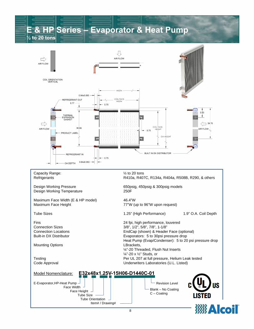
Capacity Range: ½ to 20 tonsRefrigerants R410a, R407C, R134a, R404a, R508B, R290, & others
Design Working Pressure 650psig, 450psig & 300psig modelsDesign Working Temperature 250F
Maximum Face Width (E & HP model) 46.4”WMaximum Face Height 77”W (up to 96”W upon request)
Tube Sizes 1.25” (High Performance) 1.9” O.A. Coil Depth
Fins 24 fpi, high performance, louveredConnection Sizes 3/8”, 1/2”, 5/8”, 7/8”, 1-1/8”Connection Locations EndCap (shown) & Header Face (optional)Built-in DX Distributor Evaporators: 5 to 30psi pressure drop
Heat Pump (Evap/Condenser): 5 to 20 psi pressure dropMounting Options LBrackets,
¼”-20 Threaded, Flush Nut Inserts¼”-20 x ½” Studs, or
Testing Per UL 207 at full pressure, Helium Leak testedCode Approval Underwriters Laboratories (U.L. Listed)
Model Nomenclature: E32x48x1.25V-15H06-D1440C-01
E-Evaporator,HP-Heat PumpFace Width
Face HeightTube Size
Tube OrientationItem# / Drawing#
E & HP Series – Evaporator & Heat Pump½ to 20 tons
Blank – No CoatingC – Coating
Revision Level
8
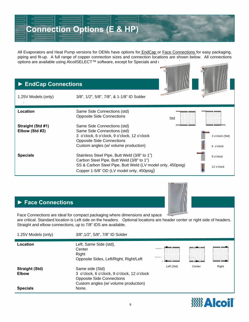
► EndCap Connections
1.25V Models (only) 3/8”, 1/2”, 5/8”, 7/8”, & 1-1/8” ID Solder.
Location Same Side Connections (std)Opposite Side Connections
Straight (Std #1) Same Side Connections (std)Elbow (Std #2) Same Side Connections (std)
3 o’clock, 6 o’clock, 9 o’clock, 12 o’clock Opposite Side ConnectionsCustom angles (w/ volume production)
Specials Stainless Steel Pipe, Butt Weld (3/8” to 1”)Carbon Steel Pipe, Butt Weld (3/8” to 1”)SS & Carbon Steel Pipe, Butt Weld (LV model only, 450psig)Copper 1-5/8” OD (LV model only, 450psig)
Connection Options (E & HP)
All Evaporators and Heat Pump versions for OEMs have options for EndCap or Face Connections for easy packaging,piping and fit-up. A full range of copper connection sizes and connection locations are shown below. All connectionsoptions are available using AlcoilSELECT™ software, except for Specials and custom angles..
Std
9
3 o’clock (Std)
6 o’clock
9 o’clock
12 o’clock
Left (Std) Center Right
► Face Connections
Face Connections are ideal for compact packaging where dimensions and spaceare critical. Standard location is Left side on the headers. Optional locations are header center or right side of headers. Straight and elbow connections, up to 7/8” IDS are available.
1.25V Models (only) 3/8”,1/2”, 5/8”, 7/8” ID Solder.
Location Left, Same Side (std), CenterRightOpposite Sides, Left/Right, Right/Left
Straight (Std) Same side (Std)Elbow 3 o’clock, 6 o’clock, 9 o’clock, 12 o’clock
Opposite Side ConnectionsCustom angles (w/ volume production)
Specials None.
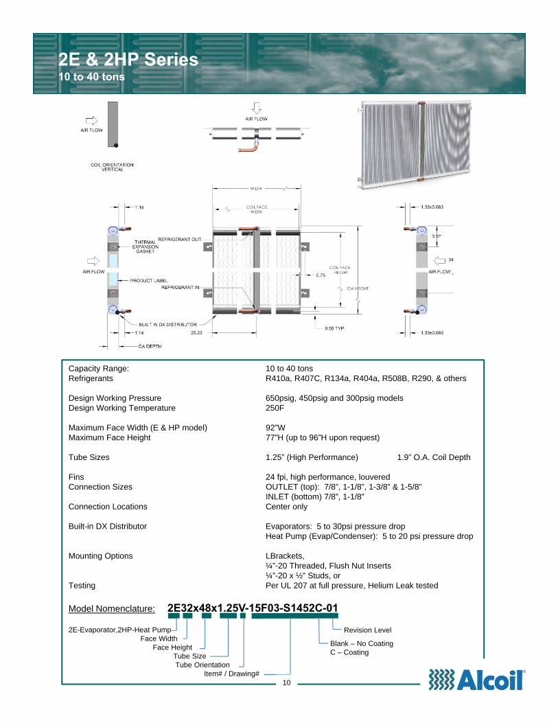
Capacity Range: 10 to 40 tonsRefrigerants R410a, R407C, R134a, R404a, R508B, R290, & others
Design Working Pressure 650psig, 450psig and 300psig modelsDesign Working Temperature 250F
Maximum Face Width (E & HP model) 92”WMaximum Face Height 77”H (up to 96”H upon request)
Tube Sizes 1.25” (High Performance) 1.9” O.A. Coil Depth
Fins 24 fpi, high performance, louveredConnection Sizes OUTLET (top): 7/8”, 1-1/8”, 1-3/8” & 1-5/8”
INLET (bottom) 7/8”, 1-1/8”Connection Locations Center only
Built-in DX Distributor Evaporators: 5 to 30psi pressure dropHeat Pump (Evap/Condenser): 5 to 20 psi pressure drop
Mounting Options LBrackets, ¼”-20 Threaded, Flush Nut Inserts¼”-20 x ½” Studs, or
Testing Per UL 207 at full pressure, Helium Leak tested
Model Nomenclature: 2E32x48x1.25V-15F03-S1452C-01
2E-Evaporator,2HP-Heat PumpFace Width
Face HeightTube SizeTube Orientation
Item# / Drawing#
2E & 2HP Series10 to 40 tons
Blank – No CoatingC – Coating
Revision Level
10
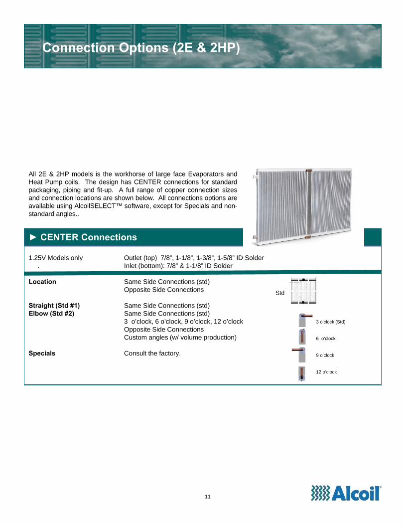
► CENTER Connections
1.25V Models only Outlet (top) 7/8”, 1-1/8”, 1-3/8”, 1-5/8” ID Solder. Inlet (bottom): 7/8” & 1-1/8” ID Solder
Location Same Side Connections (std)Opposite Side Connections
Straight (Std #1) Same Side Connections (std)Elbow (Std #2) Same Side Connections (std)
3 o’clock, 6 o’clock, 9 o’clock, 12 o’clock Opposite Side ConnectionsCustom angles (w/ volume production)
Specials Consult the factory.
Connection Options (2E & 2HP)
All 2E & 2HP models is the workhorse of large face Evaporators andHeat Pump coils. The design has CENTER connections for standardpackaging, piping and fit-up. A full range of copper connection sizesand connection locations are shown below. All connections options areavailable using AlcoilSELECT™ software, except for Specials and non-standard angles..
Std
11
3 o’clock (Std)
6 o’clock
9 o’clock
12 o’clock
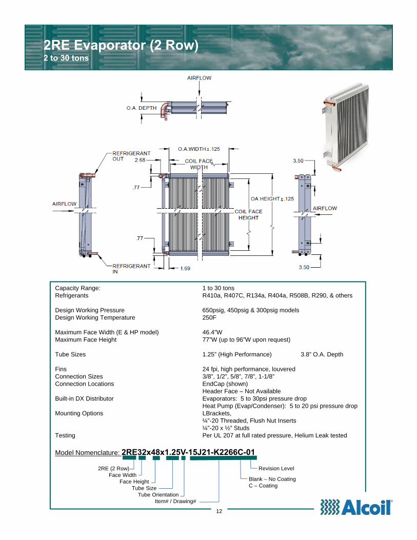
Capacity Range: 1 to 30 tonsRefrigerants R410a, R407C, R134a, R404a, R508B, R290, & others
Design Working Pressure 650psig, 450psig & 300psig modelsDesign Working Temperature 250F
Maximum Face Width (E & HP model) 46.4”WMaximum Face Height 77”W (up to 96”W upon request)
Tube Sizes 1.25” (High Performance) 3.8” O.A. Depth
Fins 24 fpi, high performance, louveredConnection Sizes 3/8”, 1/2”, 5/8”, 7/8”, 1-1/8”Connection Locations EndCap (shown)
Header Face – Not AvailableBuilt-in DX Distributor Evaporators: 5 to 30psi pressure drop
Heat Pump (Evap/Condenser): 5 to 20 psi pressure dropMounting Options LBrackets,
¼”-20 Threaded, Flush Nut Inserts¼”-20 x ½” Studs
Testing Per UL 207 at full rated pressure, Helium Leak tested
Model Nomenclature: 2RE32x48x1.25V-15J21-K2266C-01
2RE (2 Row)Face Width
Face HeightTube Size
Tube OrientationItem# / Drawing#
2RE Evaporator (2 Row)2 to 30 tons
Blank – No CoatingC – Coating
Revision Level
12
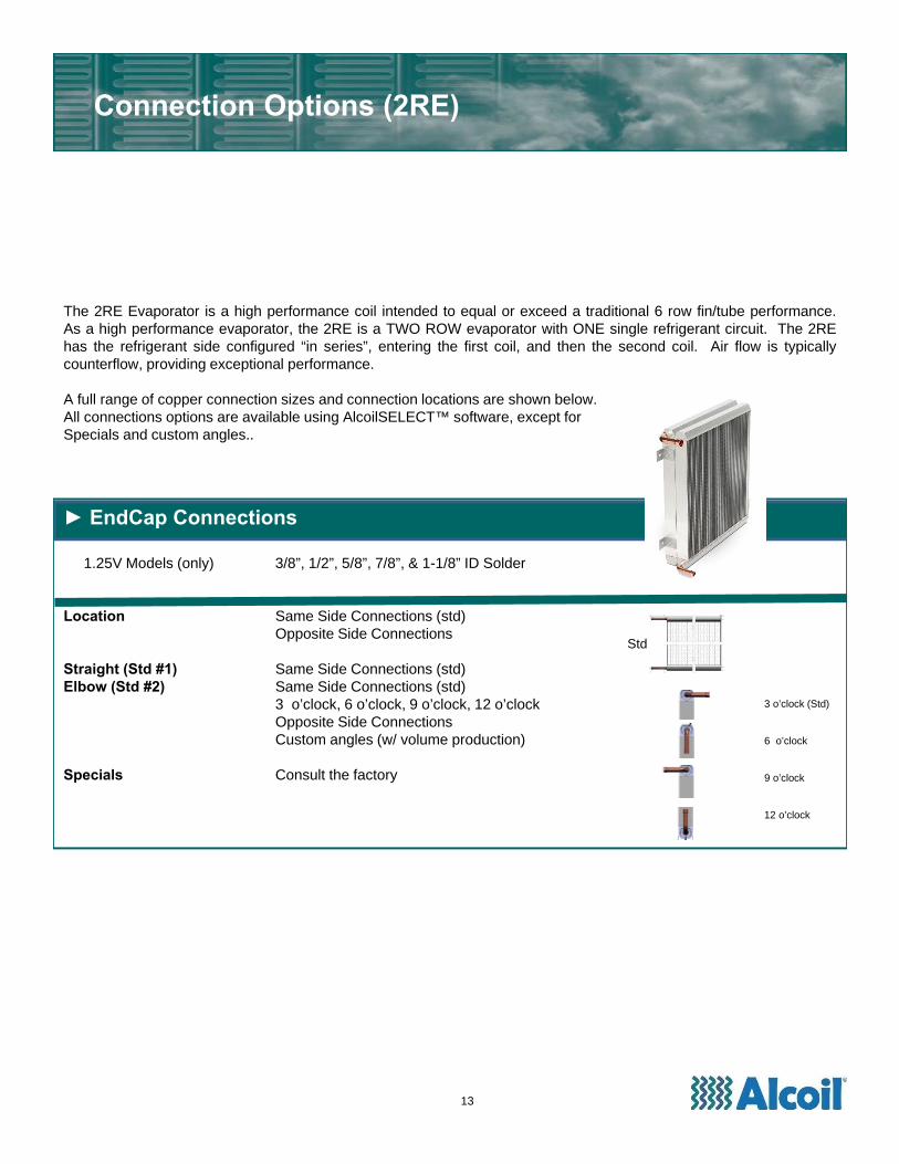
► EndCap Connections
1.25V Models (only) 3/8”, 1/2”, 5/8”, 7/8”, & 1-1/8” ID Solder
Location Same Side Connections (std)Opposite Side Connections
Straight (Std #1) Same Side Connections (std)Elbow (Std #2) Same Side Connections (std)
3 o’clock, 6 o’clock, 9 o’clock, 12 o’clock Opposite Side ConnectionsCustom angles (w/ volume production)
Specials Consult the factory
Connection Options (2RE)
The 2RE Evaporator is a high performance coil intended to equal or exceed a traditional 6 row fin/tube performance.As a high performance evaporator, the 2RE is a TWO ROW evaporator with ONE single refrigerant circuit. The 2REhas the refrigerant side configured “in series”, entering the first coil, and then the second coil. Air flow is typicallycounterflow, providing exceptional performance.
A full range of copper connection sizes and connection locations are shown below.All connections options are available using AlcoilSELECT™ software, except forSpecials and custom angles..
Std
13
3 o’clock (Std)
6 o’clock
9 o’clock
12 o’clock
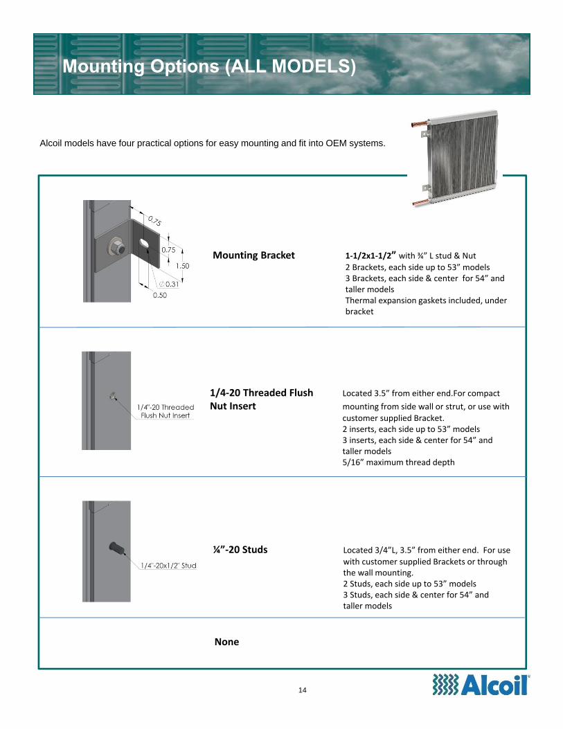
Alcoil models have four practical options for easy mounting and fit into OEM systems.
Mounting Options (ALL MODELS)
Mounting Bracket 1‐1/2x1‐1/2” with ¾” L stud & Nut2 Brackets, each side up to 53” models3 Brackets, each side & center for 54” and taller modelsThermal expansion gaskets included, under bracket
¼”‐20 Studs Located 3/4”L, 3.5” from either end. For use
with customer supplied Brackets or through the wall mounting.2 Studs, each side up to 53” models3 Studs, each side & center for 54” and taller models
1/4‐20 Threaded Flush Located 3.5” from either end.For compact
Nut Insert mounting from side wall or strut, or use with
customer supplied Bracket.2 inserts, each side up to 53” models3 inserts, each side & center for 54” and taller models5/16” maximum thread depth
None
14
15
Application Tips
Evaporator vs Heat Pump (Condenser) ModelsThe E, 2E, and 2RE models are DX Evaporators designed as strictly cooling coils. Total thermal heat transfer is acombination of “sensible heat load” and “latent heat load” from dehumidification. Evaporator models have an optimallydesigned DX Distributor for proper operation and part load performance.
The HP and 2HP models are also DX Evaporators, however, the DX Distributor is selected with a lower refrigerantpressure drop, such that the coil will also work as a Condenser in reverse mode.
Thus in this Application Section, all coils are assumed to be Evaporators. Special requirements or considerations forreverse cycle Heat Pump operation will be noted.
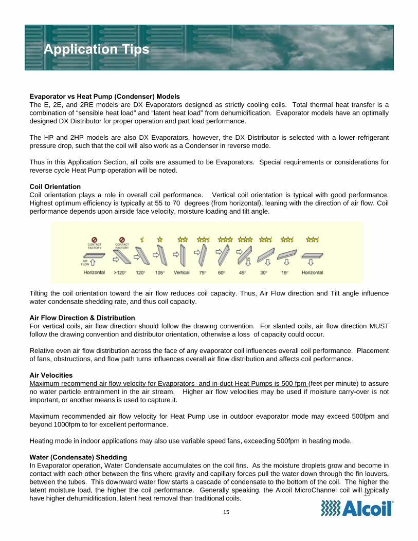
Coil OrientationCoil orientation plays a role in overall coil performance. Vertical coil orientation is typical with good performance.Highest optimum efficiency is typically at 55 to 70 degrees (from horizontal), leaning with the direction of air flow. Coilperformance depends upon airside face velocity, moisture loading and tilt angle.
Tilting the coil orientation toward the air flow reduces coil capacity. Thus, Air Flow direction and Tilt angle influencewater condensate shedding rate, and thus coil capacity.
Air Flow Direction & DistributionFor vertical coils, air flow direction should follow the drawing convention. For slanted coils, air flow direction MUSTfollow the drawing convention and distributor orientation, otherwise a loss of capacity could occur.
Relative even air flow distribution across the face of any evaporator coil influences overall coil performance. Placementof fans, obstructions, and flow path turns influences overall air flow distribution and affects coil performance.
Air VelocitiesMaximum recommend air flow velocity for Evaporators and in-duct Heat Pumps is 500 fpm (feet per minute) to assureno water particle entrainment in the air stream. Higher air flow velocities may be used if moisture carry-over is notimportant, or another means is used to capture it.
Maximum recommended air flow velocity for Heat Pump use in outdoor evaporator mode may exceed 500fpm andbeyond 1000fpm to for excellent performance.
Heating mode in indoor applications may also use variable speed fans, exceeding 500fpm in heating mode.
Water (Condensate) SheddingIn Evaporator operation, Water Condensate accumulates on the coil fins. As the moisture droplets grow and become incontact with each other between the fins where gravity and capillary forces pull the water down through the fin louvers,between the tubes. This downward water flow starts a cascade of condensate to the bottom of the coil. The higher thelatent moisture load, the higher the coil performance. Generally speaking, the Alcoil MicroChannel coil will typicallyhave higher dehumidification, latent heat removal than traditional coils.
15
.
Application Tips
Non-Dehumidifying EnvironmentsIn computer applications, data centers and applications with minimal dehumidification, the Alcoil Microchannel isdesigned to have high performance sensible load capacity. A customer supplied drain pan is recommended, if humidoperation ere to occur, such as cabinet doors open during operation.
Condensate Drain PanThe coil shoud be mounted above a condensate drain pan and should not sit in the drain pan with condensate. This assures longer coil life and avoids potential corrosion, bacteria, and other issues. The coil can rest on a ledge or protrusion of the drain pan, with suitable material compatibility. Acceptable materials include PVC & other plastics, aluminum, stainless steel and epoxy coated metals.
Refrigerant Side Alcoil’s Microchannel Evaporators are manufactured as 650psig, 450psig and 300psig versions that can be used with R410a (650psig model), R407C, R134a, R404A, R508B, and number of other refrigerants. For other refrigerants such as Ammonia and Propane, please contact the factory for custom models.
Heat Pump models are manufactured only as 650psig and 450psig versions, depending upon the refrigerant.
Because all Alcoil Evaporators use vertical micro-tubes, upward evaporative flow pushes refrigerant gas, liquid andentrained compressor through the coil. MicroChannel tube dynamics, combined with the DX Distributor system, ensureno oil entrapment at full load and part load.
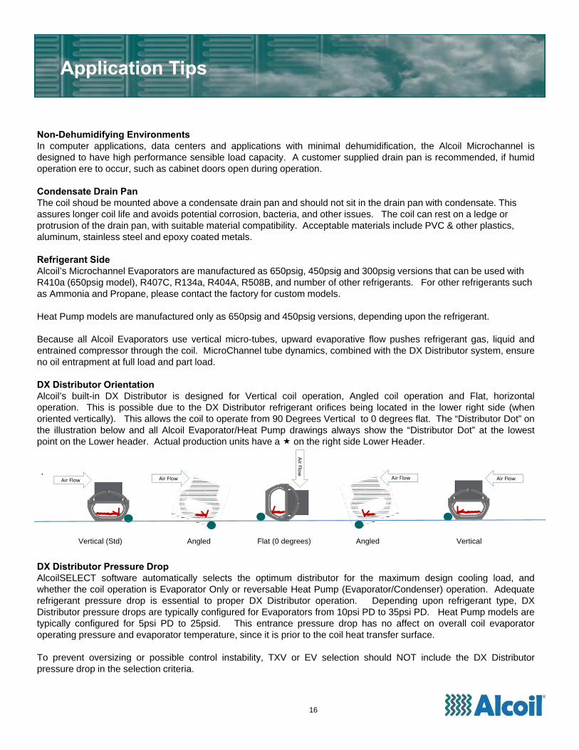
DX Distributor OrientationAlcoil’s built-in DX Distributor is designed for Vertical coil operation, Angled coil operation and Flat, horizontaloperation. This is possible due to the DX Distributor refrigerant orifices being located in the lower right side (whenoriented vertically). This allows the coil to operate from 90 Degrees Vertical to 0 degrees flat. The “Distributor Dot” onthe illustration below and all Alcoil Evaporator/Heat Pump drawings always show the “Distributor Dot” at the lowestpoint on the Lower header. Actual production units have a on the right side Lower Header.
DX Distributor Pressure DropAlcoilSELECT software automatically selects the optimum distributor for the maximum design cooling load, andwhether the coil operation is Evaporator Only or reversable Heat Pump (Evaporator/Condenser) operation. Adequaterefrigerant pressure drop is essential to proper DX Distributor operation. Depending upon refrigerant type, DXDistributor pressure drops are typically configured for Evaporators from 10psi PD to 35psi PD. Heat Pump models aretypically configured for 5psi PD to 25psid. This entrance pressure drop has no affect on overall coil evaporatoroperating pressure and evaporator temperature, since it is prior to the coil heat transfer surface.
To prevent oversizing or possible control instability, TXV or EV selection should NOT include the DX Distributorpressure drop in the selection criteria.
Vertical (Std) Angled Flat (0 degrees) Angled Vertical
Air Flow Air Flow
Air Flo
w
Air FlowAir Flow
16

Refrigerant ChargeWhen using an Alcoil microchannel Evaporator or Heat Pump coil, the refrigerant system charge will typically use 30%to 60% less refrigerant than a traditional fin/tube coil (excluding a receiver, if used). Overcharging might system willresult in higher head pressure and loss of system capacity.
The following procedure is recommended: 1) At full load or near full load operating conditions and by weight ofrefrigerant, put approximately 1/3rd the calculated charge in the refrigeration system. Let the system stabilize andcheck for gas bubbles in the liquid line sight glass. 2) Incrementally, add small amounts (.1oz) of refrigerant and waitfor the system to stabilize. 3) When there are few or no gas bubbles entering the expansion valve, then the charge ismost likely correct. 4) If the system is operating with higher head pressure than design, extract refrigerant charge fromthe system. As a second method, typical condenser refrigerant subcooling is 5F to 7F. Above 10F subcooling typicallyindicates an over-charged system.
System Operation & ControlRecommended Evaporator Superheat is 6F. Because the coil has micro-port tubes refrigerant liquid will not pass outthe heat exchanger at low superheat temperatures. Thus, for optimum efficiency, a lower Superheat <10F operation isrecommended. Higher superheat operation will lower coil capacity.
TXV, EV, & Hot Gas operation – In special systems, an over-reacting TXV or EV, or oversized TXV can cause systemoscillation or high head and low suction pressure. Slower response EV control will typically remedy this situation.Where hot gas bypass is used on with the evaporator, a slow response modulating valve is recommended to preventhigh pressure cutout due to rapid refrigerant transfer to the condenser and to prevent thermal shock and prematurefailure of the coil.
a) Low Evaporator Suction Operation – Recommended minimum evaporator suction temperature is 26F +/- 2F,depending upon the airside flow rate and other operating conditions. Frost build up may occur in this temperaturerange. Freezing or full freezing of the coil may cause coil failure.
b) Defrost Cycle (Heat Pump models) – Like all heat pump coils, outdoor operation must include a defrost cycle.Defrost time and frequency is dependent upon operating conditions, temperatures and air flow rates. Theequipment OEM is responsible for developing the defrost cycle for the system.
c) High Ambient or High Head Operation is possible with Alcoil’s 1.25 model, using proper head pressure control, fanspeed control and equipment controls to take advantage of the MicroChannel’s higher heat of rejection capabilities.For Heat Pumps, this
d) Fan Control – Recommended fan control is single speed, two speed or variable speed.
e) Air Flow Distribution can effect coil overall performance. Fan placement, obstructions, change of air flow, and otherfactors can effect overall coil performance. On new or complex designs, air annometer checks are recommendedon new equipment designs.
Application Tips
17
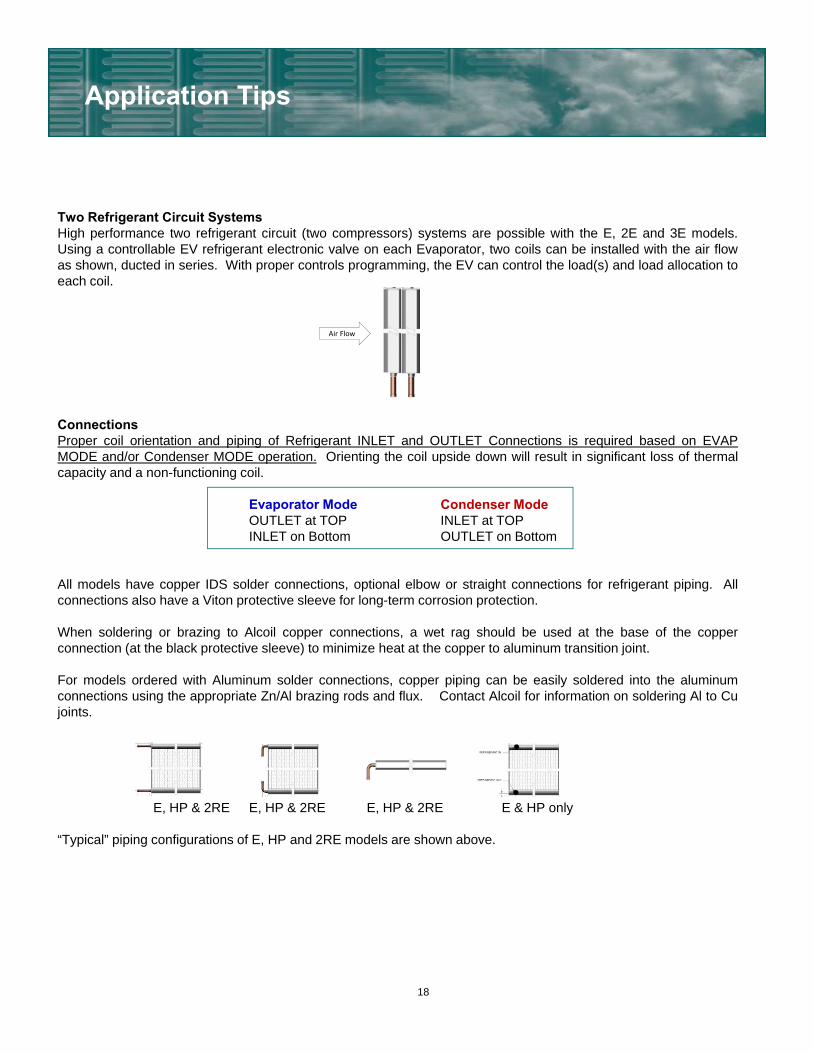
Two Refrigerant Circuit SystemsHigh performance two refrigerant circuit (two compressors) systems are possible with the E, 2E and 3E models.Using a controllable EV refrigerant electronic valve on each Evaporator, two coils can be installed with the air flowas shown, ducted in series. With proper controls programming, the EV can control the load(s) and load allocation toeach coil.
ConnectionsProper coil orientation and piping of Refrigerant INLET and OUTLET Connections is required based on EVAPMODE and/or Condenser MODE operation. Orienting the coil upside down will result in significant loss of thermalcapacity and a non-functioning coil.
Evaporator Mode Condenser ModeOUTLET at TOP INLET at TOPINLET on Bottom OUTLET on Bottom
All models have copper IDS solder connections, optional elbow or straight connections for refrigerant piping. Allconnections also have a Viton protective sleeve for long-term corrosion protection.
When soldering or brazing to Alcoil copper connections, a wet rag should be used at the base of the copperconnection (at the black protective sleeve) to minimize heat at the copper to aluminum transition joint.
For models ordered with Aluminum solder connections, copper piping can be easily soldered into the aluminumconnections using the appropriate Zn/Al brazing rods and flux. Contact Alcoil for information on soldering Al to Cujoints.
E, HP & 2RE E, HP & 2RE E, HP & 2RE E & HP only
“Typical” piping configurations of E, HP and 2RE models are shown above.
Application Tips
Air Flow
18
Application Tips
Galvanic/ElectricalFor most equipment applications, galvanic or stray current considerations are not necessary. Painted sheet metalparts, plastic parts and stainless steel interfaces with the aluminum coil(s) are normally accepted practice. Withgalvanize sheet metal, rubber can be used to prevent localized loss of galvanized zinc or interaction with the coil. Formobile, shipboard, or applications where equipment grounding may be an issue, coil electrical isolation from theequipment frame may be necessary, except for refrigerant connections.
CorrosionDue to the all aluminum construction, brazed aluminum heat exchangers are subject to significantly less galvaniccorrosion than traditional fin/tube coils, in that there are no dissimilar metals. Normal installations should not requirecoatings, except in environments corrosive to aluminum.
Sea coast and marine use is acceptable. Epoxy or Thermoguard Coating(s) is optional.
For applications with pollution, chemical emissions, exposure to moist air, or corrosive environments, coil coatings mustbe used. See Coatings Option Section.
Coil CleaningRoutine cleaning of particulates from the coil can be performed with high pressure air. Routine cleaning of dirt andgrime may be performed with high pressure water, including general detergents. Avoid chemical cleaning. In anycases, water pressure must be controlled to prevent damage to the fins. A coil filter or protective mesh cloth can alsobe used in the equipment design, if particulates are an issue.
inches mm inches mm
10 250 0.011 0.27
15 375 0.016 0.40
20 500 0.021 0.53
25 625 0.026 0.67
30 750 0.032 0.80
40 1000 0.042 1.07
50 1250 0.053 1.33
60 1500 0.063 1.60
70 1750 0.074 1.87
80 2000 0.084 2.13
90 2250 0.095 2.40
100 2500 0.105 2.67
110 2750 0.116 2.93
120 3000 0.126 3.20
Minimum Allowance for
Thermal Expansion
Coil Dimensions (Width & Height)
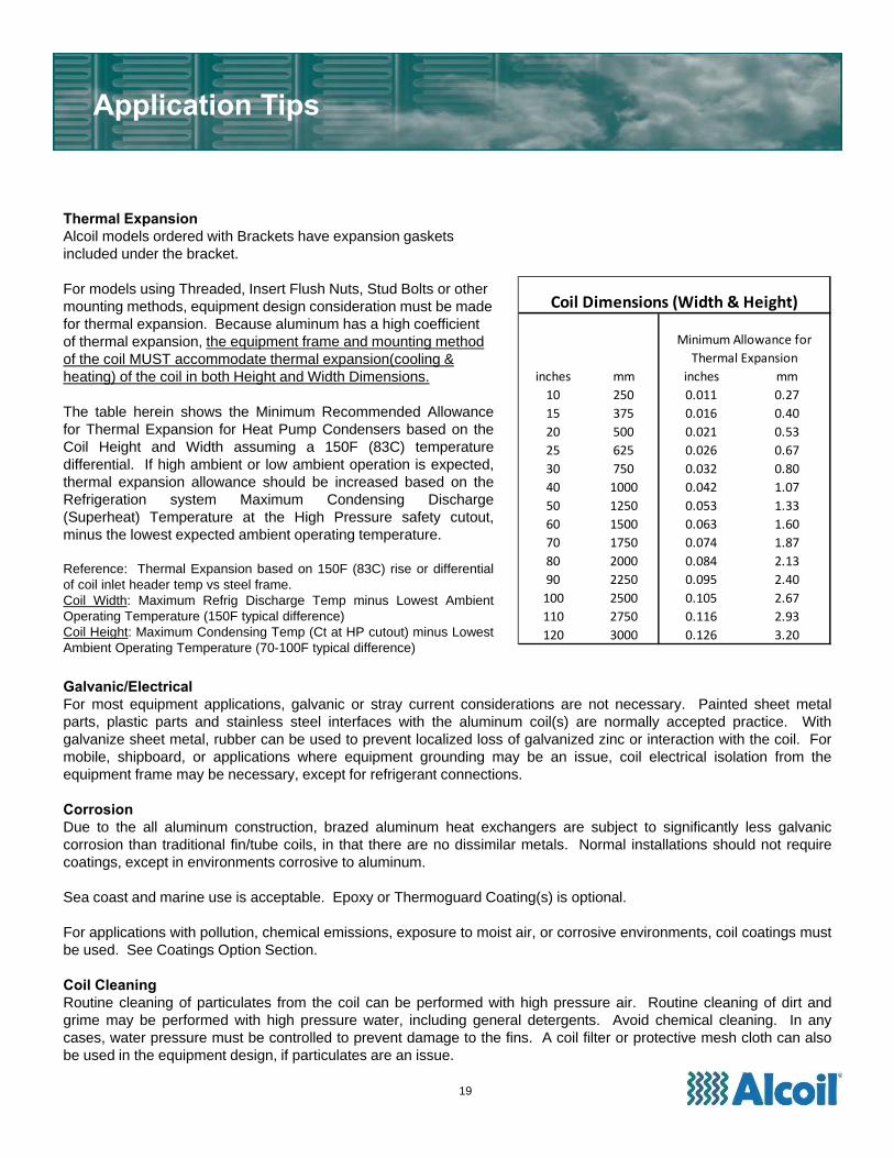
Thermal ExpansionAlcoil models ordered with Brackets have expansion gaskets included under the bracket.
For models using Threaded, Insert Flush Nuts, Stud Bolts or other mounting methods, equipment design consideration must be made for thermal expansion. Because aluminum has a high coefficient of thermal expansion, the equipment frame and mounting method of the coil MUST accommodate thermal expansion(cooling & heating) of the coil in both Height and Width Dimensions.
The table herein shows the Minimum Recommended Allowancefor Thermal Expansion for Heat Pump Condensers based on theCoil Height and Width assuming a 150F (83C) temperaturedifferential. If high ambient or low ambient operation is expected,thermal expansion allowance should be increased based on theRefrigeration system Maximum Condensing Discharge(Superheat) Temperature at the High Pressure safety cutout,minus the lowest expected ambient operating temperature.
Reference: Thermal Expansion based on 150F (83C) rise or differentialof coil inlet header temp vs steel frame.Coil Width: Maximum Refrig Discharge Temp minus Lowest AmbientOperating Temperature (150F typical difference)Coil Height: Maximum Condensing Temp (Ct at HP cutout) minus LowestAmbient Operating Temperature (70-100F typical difference)
19
Alcoil offers two coating options:1) Epoxy Electrocoat2) Thermoguard Polyurethane
Epoxy Electrocoat
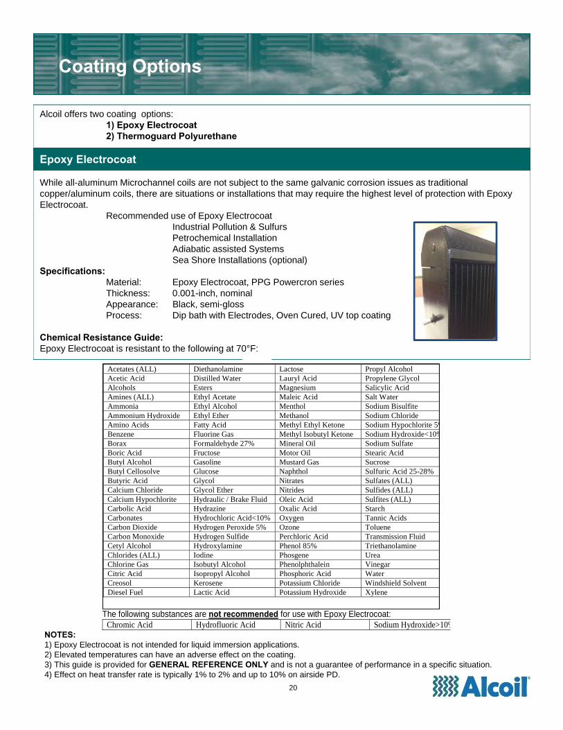
While all-aluminum Microchannel coils are not subject to the same galvanic corrosion issues as traditional copper/aluminum coils, there are situations or installations that may require the highest level of protection with Epoxy Electrocoat.
Recommended use of Epoxy ElectrocoatIndustrial Pollution & Sulfurs Petrochemical InstallationAdiabatic assisted SystemsSea Shore Installations (optional)
Specifications:Material: Epoxy Electrocoat, PPG Powercron seriesThickness: 0.001-inch, nominalAppearance: Black, semi-glossProcess: Dip bath with Electrodes, Oven Cured, UV top coating
Chemical Resistance Guide:Epoxy Electrocoat is resistant to the following at 70°F:
Coating Options
Acetates (ALL) Diethanolamine Lactose Propyl Alcohol Acetic Acid Distilled Water Lauryl Acid Propylene Glycol Alcohols Esters Magnesium Salicylic Acid Amines (ALL) Ethyl Acetate Maleic Acid Salt Water Ammonia Ethyl Alcohol Menthol Sodium Bisulfite Ammonium Hydroxide Ethyl Ether Methanol Sodium Chloride Amino Acids Fatty Acid Methyl Ethyl Ketone Sodium Hypochlorite 5%Benzene Fluorine Gas Methyl Isobutyl Ketone Sodium Hydroxide<10%Borax Formaldehyde 27% Mineral Oil Sodium Sulfate Boric Acid Fructose Motor Oil Stearic Acid Butyl Alcohol Gasoline Mustard Gas SucroseButyl Cellosolve Glucose Naphthol Sulfuric Acid 25-28% Butyric Acid Glycol Nitrates Sulfates (ALL) Calcium Chloride Glycol Ether Nitrides Sulfides (ALL) Calcium Hypochlorite Hydraulic / Brake Fluid Oleic Acid Sulfites (ALL) Carbolic Acid Hydrazine Oxalic Acid StarchCarbonates Hydrochloric Acid<10% Oxygen Tannic Acids Carbon Dioxide Hydrogen Peroxide 5% Ozone Toluene Carbon Monoxide Hydrogen Sulfide Perchloric Acid Transmission Fluid Cetyl Alcohol Hydroxylamine Phenol 85% Triethanolamine Chlorides (ALL) Iodine Phosgene UreaChlorine Gas Isobutyl Alcohol Phenolphthalein Vinegar Citric Acid Isopropyl Alcohol Phosphoric Acid Water Creosol Kerosene Potassium Chloride Windshield Solvent Diesel Fuel Lactic Acid Potassium Hydroxide Xylene
The following substances are not recommended for use with Epoxy Electrocoat:
Chromic Acid Hydrofluoric Acid Nitric Acid Sodium Hydroxide>10% NOTES:
1) Epoxy Electrocoat is not intended for liquid immersion applications.2) Elevated temperatures can have an adverse effect on the coating.3) This guide is provided for GENERAL REFERENCE ONLY and is not a guarantee of performance in a specific situation.4) Effect on heat transfer rate is typically 1% to 2% and up to 10% on airside PD.
20
AlcoilSELECT™ Software
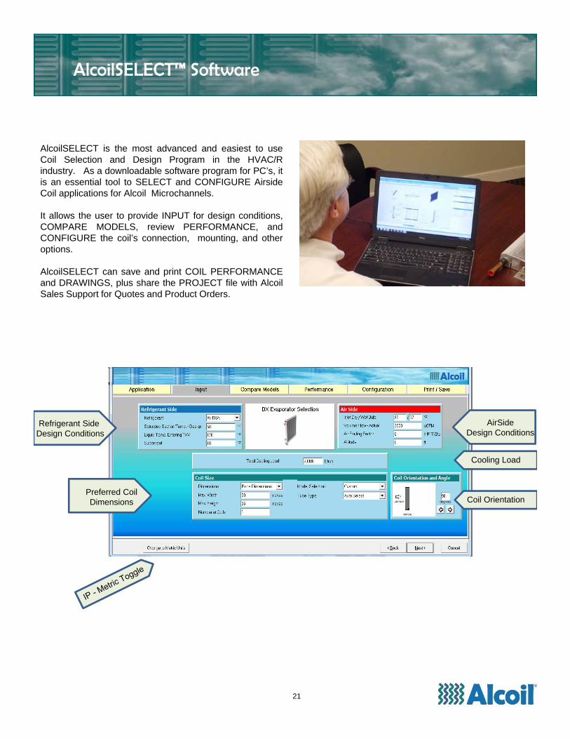
AlcoilSELECT is the most advanced and easiest to useCoil Selection and Design Program in the HVAC/Rindustry. As a downloadable software program for PC’s, itis an essential tool to SELECT and CONFIGURE AirsideCoil applications for Alcoil Microchannels.
It allows the user to provide INPUT for design conditions,COMPARE MODELS, review PERFORMANCE, andCONFIGURE the coil’s connection, mounting, and otheroptions.
AlcoilSELECT can save and print COIL PERFORMANCEand DRAWINGS, plus share the PROJECT file with AlcoilSales Support for Quotes and Product Orders.
Refrigerant Side Design Conditions
Preferred CoilDimensions
AirSideDesign Conditions
Cooling Load
Coil Orientation
21
22
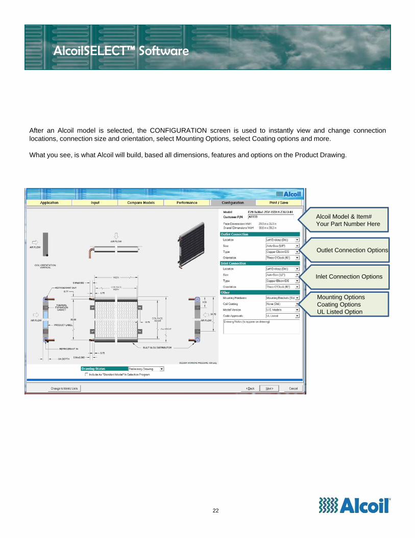
Outlet Connection Options
Inlet Connection Options
Mounting OptionsCoating OptionsUL Listed Option
Alcoil Model & Item#Your Part Number Here
After an Alcoil model is selected, the CONFIGURATION screen is used to instantly view and change connectionlocations, connection size and orientation, select Mounting Options, select Coating options and more.
What you see, is what Alcoil will build, based all dimensions, features and options on the Product Drawing.
AlcoilSELECT™ Software
AlcoilSELECT™ Software
23
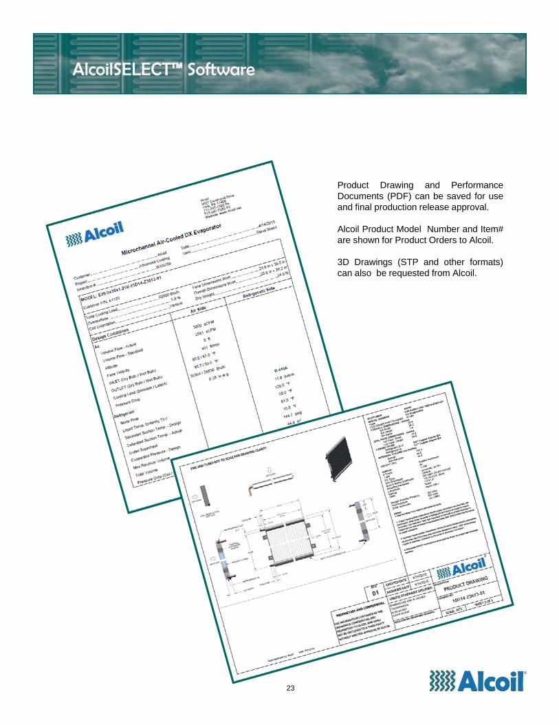
Product Drawing and PerformanceDocuments (PDF) can be saved for useand final production release approval.
Alcoil Product Model Number and Item#are shown for Product Orders to Alcoil.
3D Drawings (STP and other formats)can also be requested from Alcoil.
AlcoilSELECT™ Software
24
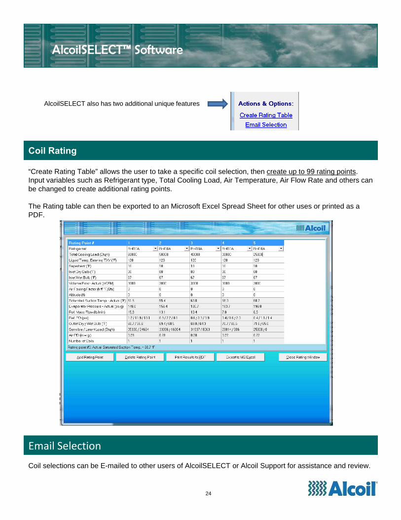
AlcoilSELECT also has two additional unique features
Coil Rating
“Create Rating Table” allows the user to take a specific coil selection, then create up to 99 rating points. Input variables such as Refrigerant type, Total Cooling Load, Air Temperature, Air Flow Rate and others can be changed to create additional rating points.
The Rating table can then be exported to an Microsoft Excel Spread Sheet for other uses or printed as a PDF.
Email Selection
Coil selections can be E-mailed to other users of AlcoilSELECT or Alcoil Support for assistance and review.
The following terms and conditions apply to all purchase orders, contracts or shipments between Alcoil ("Alcoil") and any customer ("Customer") for which Alcoil provides equipment, products, orservices:
OFFER AND ACCEPTANCE. The products and services described are offered for sale by Alcoil subject to all of the terms and conditions stated herein. This writing constitutes an offer of sale,which is expressly limited to the products, services, terms, and conditions stated herein. By submitting a purchase order or other written response to this offer of sale, or by accepting delivery of theproducts and services offered herein, Customer accepts all of the terms and conditions contained herein. No additional, changed, or conflicting terms and conditions appearing in Customer'spurchase order or other written response to this offer shall be binding upon Alcoil unless expressly agreed to in writing by Alcoil.
PAYMENT TERMS. Payment terms are NET 30 Days from Date of Invoice, Subject to credit approval by Alcoil's Credit Dept. Shipments, deliveries, and performance of work by Alcoil shall besubject to the continuing approval of Alcoil's Credit Dept., which may require full or partial payment in advance if the financial condition of Customer (in the sole opinion of Alcoil's Credit Dept.) doesnot justify continuance of work by Alcoil on the terms of payment agreed upon.
PRICES. All Prices are F.O.B, York, Pennsylvania, USA. All transportation expenses shall be paid by Customer, either Freight Collect, or Pre-paid/Add to Invoice. Alcoil reserves the right to adjustprices (surcharge or credit) at time of order entry due to material cost fluctuations.
TITLE AND RISK OF LOSS. Title to any products shipped by Alcoil shall pass to Customer upon delivery by Alcoil to the carrier. Risk of loss or damage to products in transit is assumed byCustomer, and Customer shall bear responsibility for filing and pursuing any claims for loss or damage with the carrier.
DELIVERY. Shipping dates are approximate only based upon prompt receipt from Customer of all information required by Alcoil to meet Customer expectations. Alcoil shall not be liable for delaysin delivery or failure to perform hereunder where such delay or failure results from: (i) causes beyond the reasonable control of Alcoil, (ii) acts of God, acts of Customer, or acts of civil or militaryauthorities, (iii) inability of Alcoil to obtain necessary labor, materials, components, or facilities, or (iv) any other commercial impracticability. In the event of any such delay, the date of delivery shallbe deferred for a period of time equal to the time lost by reason of the delay.
LIMITED WARRANTY OF PRODUCTS AND SERVICESLimited Warranty. Alcoil warrants its products to be free from defects in materials and workmanship under normal use and operation for a period of one (1) year from the date of productinstallation and no more than one (1) year and six (6) months from date of product delivery, as evidenced by Alcoil shipping records (the "Warranty Period"). For any materials or workmanshipdetermined by Alcoil to be defective within the Warranty Period, Alcoil shall, at its option, either: (i) repair any such defective material, component part, or service, or (ii) make available to Customer,FOB York, Pennsylvania, any repaired or replacement parts or materials to replace such defective material, component part, or service, or (iii) refund to Customer the amount paid by Customer forthe defective product or service provided by Alcoil hereunder.Exclusions. The above warranty shall not apply to any product that has been: (i) subjected to misuse, negligence or accident; (ii) misapplied by Customer or others for an improper use; (iii)installed in an improper manner; (iv) modified or repaired contrary to Alcoil recommendations or generally accepted practices or procedures in the industry, or (v) operated under conditions whichmay cause product failure. Alcoil shall not be responsible for any costs associated with the product damage, loss or replacement due to freeze-up, improper water treatment, improper cleaning, fluidchemistry exceeding Alcoil’s recommendations, clogging and debris, fouling, corrosion, galvanic induced corrosion, vibration, thermal cycling, hydraulic shock, over-pressurization, compressorfailure, system contamination, loss of protective coating (where applied) and any other operating or system condition which may cause product failure.
Warranty Procedures. If any Alcoil product is believed to be defective, written notice of such warranty claim must be made and an RMA# (Return Authorization) must be issued by Alcoil, 3627Sandhurst Dr, York, PA 17406. Ph: 717-347-7500 Alcoil, at its option, may require return of any product believed to be defective for purposes of testing, inspection and verification, as arequirement for potential warranty coverage.
Disclaimer of Further Warranties. THE LIMITED WARRANTY SET FORTH ABOVE IS THE EXCLUSIVE WARRANTY APPLICABLE TO THIS CONTRACT, AND ALCOIL EXPRESSLYDISCLAIMS ALL OTHER WARRANTIES OR REMEDIES, INCLUDING WARRANTIES OF MERCHANTABILITY AND FITNESS FOR A PARTICULAR PURPOSE, WHETHER THE SAME AREWRITTEN, VERBAL, IMPLIED, OR STATUTORY.
Limitation of Liability. Under no circumstances shall Alcoil be liable for any incidental, consequential, or special damages, losses, or expenses incurred by Customer or any third party arising fromthis offer of sale or the performance of Alcoil hereunder. Under no circumstances shall the amount of any claim for damages or liability exceed the amount paid by Customer for products andservices provided by Alcoil hereunder.
Time Limitation on Warranty Claims. No legal action or claim, whether based in tort, contract, strict liability, breach of warranty or otherwise, arising out of this offer of sale or the performance byAlcoil hereunder may be commenced more than one (1) year following expiration of the Warranty Period. Customer hereby waives any such claim or cause of action commenced after the WarrantyPeriod.
TAXES AND DUTIES. Customer shall be responsible for collection or payment of any federal, state, provincial or local taxes or duties. Any taxes which Alcoil may be required to pay or collect,under any existing or future law, with respect to the sale, purchase, delivery, storage, or use of any product or services covered hereunder shall be the responsibility of Customer.
PROPRIETARY RIGHTS
Alcoil retains the exclusive right to all trade names, service marks, trademarks and patents for which Alcoil is the lawful owner or Licensee, and Customer acknowledges that Customer acquires noright, title or interest in or to any such trade names, service marks, trademarks or patents for any reason.
JURISDICTION AND VENUE. As to litigation arising from any disputes, claims or controversy, both Customer and Alcoil: (i) submit to the exclusive general jurisdiction of the state courts of YorkCounty, Pennsylvania, the federal courts of the United States of America for the Middle District of Pennsylvania, and any appellate courts from any decision thereof; (ii) consent that any such actionor proceeding may be brought in such courts; and (iii) waive any objection that either may have to the venue of any such action or proceeding in any such court or that such action or proceedingwas brought in an inconvenient forum and each party agrees not to plead or claim the same.
ENTIRE AGREEMENT. These terms constitute the entire agreement between the parties and all prior negotiations and representations of the parties are merged herein.
PENNSYLVANIA LAW TO APPLY. Any purchase order, shipment or contract resulting from Customer's acceptance of this offer of sale shall be deemed to have been executed and delivered inYork County, Pennsylvania, and shall be construed under, and in accordance with, the laws of the Commonwealth of Pennsylvania.
WAIVER. One or more waivers of any breach of any term or condition herein shall not be construed as a waiver of any subsequent breach of the same term or condition. To be effective, anyexpress waiver must be in writing.
COLLECTION COSTS. Should Customer default in the payment of any amount owing to Alcoil for products of services, and Alcoil is required to expend costs and expenses in collecting suchamount, Alcoil shall be entitled to reimbursement for all such costs of collection (including reasonable attorney fees).
PRODUCT SELECTION AND USE. Customer shall be responsible for accurate design and operating conditions used in the selection and use of Alcoil products. Customer selection and use ofAlcoil product from published literature or Alcoil Selection software shall be at the customer’s risk as to appropriate application, design conditions and performance criteria use.
STANDARDS AND TOLERANCES. All Product Dimensions and published information is subject to change without notice. All Alcoil products furnished to Customer shall also be subject totolerances and variations consistent with usages of the trade concerning dimensions, composition and mechanical properties, and normal variations in performance characteristics and quality.
SPECIAL ORDERS. On special orders and products of custom design, a minimum of 50% of the sale price may be required upon engineering approval by the customer.
RESTOCKING AND CANCELLATION CHARGES. Alcoil reserves the right to collect costs against returned product and cancelled orders. Restocking charges of returned product costs shall be25% of the product(s) sales price, and cancellation charges shall be a minimum of 25% of the product(s) sales price, or work in progress costs incurred by Alcoil, whichever is higher.
25
Terms & Conditions
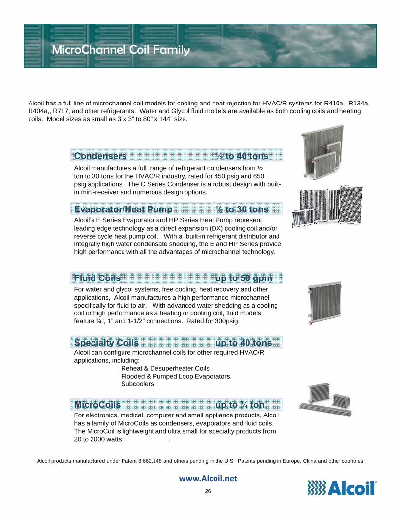
Condensers ½ to 40 tonsAlcoil manufactures a full range of refrigerant condensers from ½ ton to 30 tons for the HVAC/R industry, rated for 450 psig and 650 psig applications. The C Series Condenser is a robust design with built-in mini-receiver and numerous design options.
Evaporator/Heat Pump ½ to 30 tonsAlcoil’s E Series Evaporator and HP Series Heat Pump represent leading edge technology as a direct expansion (DX) cooling coil and/or reverse cycle heat pump coil. With a built-in refrigerant distributor and integrally high water condensate shedding, the E and HP Series provide high performance with all the advantages of microchannel technology.
Fluid Coils up to 50 gpmFor water and glycol systems, free cooling, heat recovery and other applications, Alcoil manufactures a high performance microchannel specifically for fluid to air. With advanced water shedding as a cooling coil or high performance as a heating or cooling coil, fluid models feature ¾”, 1” and 1-1/2” connections. Rated for 300psig.
Specialty Coils up to 40 tonsAlcoil can configure microchannel coils for other required HVAC/R applications, including:
Reheat & Desuperheater CoilsFlooded & Pumped Loop Evaporators.Subcoolers
MicroCoils™ up to ¾ tonFor electronics, medical, computer and small appliance products, Alcoil has a family of MicroCoils as condensers, evaporators and fluid coils. The MicroCoil is lightweight and ultra small for specialty products from 20 to 2000 watts. .
www.Alcoil.net
Alcoil has a full line of microchannel coil models for cooling and heat rejection for HVAC/R systems for R410a, R134a, R404a,, R717, and other refrigerants. Water and Glycol fluid models are available as both cooling coils and heating coils. Model sizes as small as 3”x 3” to 80” x 144” size.
www.Alcoil.net
26
MicroChannel Coil Family
Alcoil products manufactured under Patent 8,662,148 and others pending in the U.S. Patents pending in Europe, China and other countries
Alcoil 3627 Sandhurst DriveYork, PA 17406Ph: 717‐347‐7500Fax: 717‐347‐7383
www.Alcoil.net
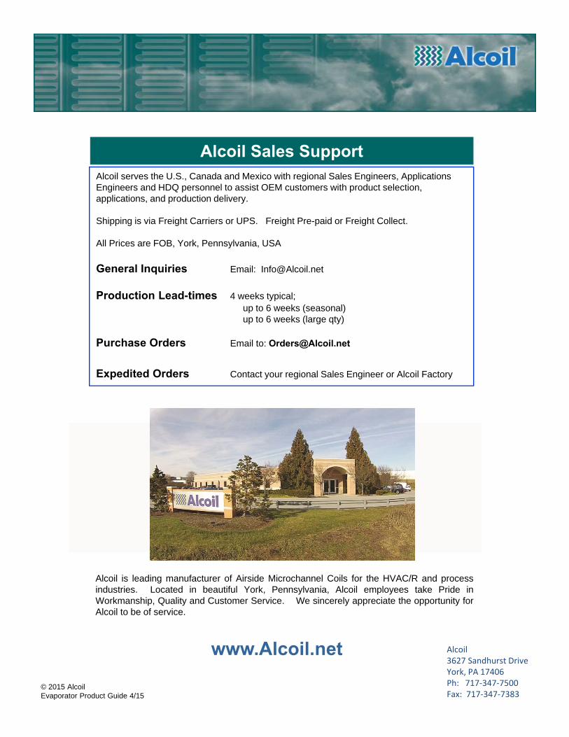
Alcoil Sales SupportAlcoil serves the U.S., Canada and Mexico with regional Sales Engineers, Applications Engineers and HDQ personnel to assist OEM customers with product selection, applications, and production delivery.
Shipping is via Freight Carriers or UPS. Freight Pre-paid or Freight Collect.
All Prices are FOB, York, Pennsylvania, USA
General Inquiries Email: [email protected]
Production Lead-times 4 weeks typical; up to 6 weeks (seasonal)up to 6 weeks (large qty)
Purchase Orders Email to: [email protected]
Expedited Orders Contact your regional Sales Engineer or Alcoil Factory
Alcoil is leading manufacturer of Airside Microchannel Coils for the HVAC/R and processindustries. Located in beautiful York, Pennsylvania, Alcoil employees take Pride inWorkmanship, Quality and Customer Service. We sincerely appreciate the opportunity forAlcoil to be of service.
© 2015 AlcoilEvaporator Product Guide 4/15


![88_10 [High Performance Steel Pipes and Tubes]](https://img.pdfslide.us/doc/110x75/552a60084a7959756d8b45ce/8810-high-performance-steel-pipes-and-tubes.jpg)