Embed Size (px)
Citation preview
8
Evanescent-Wave Pumped and Gain Coupled Whispering-Gallery-Mode Fibre Laser
Xiao-Yun Pu, Yuan-Xian Zhang and Li Feng Department of Physics, Yunnan University, Kunming, Yunnan,
China
1. Introduction
A novel Whispering–Gallery–Mode (WGM) fibre laser is demonstrated by pumping and
gain coupling with evanescent-waves in this chapter. The properties of the fibre laser,
including energy threshold, produced length and polarization of lasing emission have been
investigated. Two important applications of the fibre lasers on optoelectronics, linearly
polarized three-color lasing emission and single WGM lasing emission, are also
demonstrated in this chapter. The chapter is composed by four parts. In part one, an
evanescent wave pumped and gain coupled micro-cavity fiber laser is demonstrated by
inserting a bare fused quartz fiber into a glass capillary filled with Rhodamine 6G dye
solution, and its energy threshold properties, including the energy threshold varied with the
refractive index of the dye solution for different fiber diameters and the produced length of
lasing emission, are then investigated. In part two, the polarization properties of an
evanescent-wave pumped WGM fibre laser are investigated. It is found that there are two
kinds of polarization lasing beam emitting from the evanescent-wave pumped WGM fibre
laser under two different pump conditions. In part three, WGM fibre laser, emitting linearly
polarized three-color light, is demonstrated by pumping and gain coupling with evanescent
waves. In part four, a coupled cylinder-cavity structure, which is used to increase the free
spectral range of a WGM fiber laser, is demonstrated by binding two bare optical fibres
together, and single WGM lasing emission is realized.
2. Part-I - Threshold property of Whispering-Gallery-Mode fiber lasers pumped by evanescent-waves
In Part I, the threshold properties of Whispering–Gallery–Mode (WGM) fiber lasers pumped by evanescent-waves are investigated. Evanescent-wave gain coupled circular microcavity lasers, such as cylindrical [1-6], spherical[7,8], capillary [9,10] and fiber knot [11] lasers, have generated much interest in recent years, which are due mainly to the fact that the gain media are distributed around their resonators and their potential applications in integrated optics, optoelectronics and optofluidics [12,13] etc. As the evanescent field of a WGM in a circular cavity extends into the gain medium, the gain can be coupled into the WGM that provides optical feedback required by lasing oscillations. To optically excite the gain molecules around a circular cavity, laser beams are usually pumped from the outside of the gain medium [1-5], this pumping configuration, called side-pumping scheme, suffers a low
www.intechopen.com
Selected Topics on Optical Fiber Technology
196
pump efficiency, because the pump energy is absorbed by all of excited molecules, and only a small number of molecules residing in the WGM evanescent field contributes to the optical gain. To solve this problem, evanescent-wave pumping scheme has been used in circular cavities in recent years, such as bare optical fiber [6], capillary[9], and microfiber knot[11], which reduces lasing threshold from 200 J /pulse in the side-pumping scheme[1] to 9.2 J /pulse [9] and further to 100 nJ /pulse[11]. Optical gain in the evanescent-wave pumping scheme is produced by evanescent-waves on a fiber surface, the waves are created by a pump light that propagates within the fiber by total internal reflection. Due to a strong spatial overlap between the gain profile and the WGM evanescent field, a high pump efficiency and a long gain distance along the axis of the circular cavity have been achieved [6], which has been successfully used to invent a WGM fiber laser emitting three-wavelength-range lasing beams in a single optical fiber [14]. In the evanescent-wave pumping scheme, laser resonator is surrounded by a dye solution of
low refractive index (RI), which acts not only as the gain medium, but also the cladding
material for the pumping and circulating light in a microcavity. The penetration depth of
pump light into the dye solution determines the gain value, the smaller RI difference
between the cavity material and dye solution is, the larger gain is produced by evanescent-
wave pumping scheme. Further more, the quality factor (Q value) of a resonator determines
the cavity loss, a small RI difference between the cavity material and dye solution means a
large cavity loss, which is not benefit to lasing oscillation. Therefore, the threshold property
of an evanescent-wave pumped microcavity laser is affected strongly by the RI of cladding
solution. However, few works, either the simulations or the experiments, have been
reported to explore this important effect of the microcavity laser.
In this part, firstly, the optical gain of a microcavity fiber laser in the evanescent-wave
pumping scheme is analyzed by introducing a Gaussian distribution function of pump light,
a gain formula is derived. The energy losses related to a circular cavity, including cavity
absorption, light scattering and leakage are considered, which leads to a quality-factor
equation. Secondly, assuming the derived gain is equal to the energy loss, the energy
threshold formula is achieved that is convenient to be compared with our experimental
results. Based on the characteristics of frustrated totally internal reflection (FTIR) of pump
light traveling along an optical fiber, an attenuated factor is introduced in the threshold
energy formula, to achieve the equation for determining the produced length of lasing
emission along the axial of the optical fiber. Thirdly, an evanescent-wave pumped and gain
coupled WGM fiber laser is fabricated by inserting a bare fused quartz fiber (no cladding)
into a glass capillary filled with Rhodamine 6G dye solution, the energy threshold
properties of the laser, including the energy threshold varied with the RI of the dye solution
for different fiber diameters and the produced length of lasing emission along the fiber axis,
have been experimentally investigated. Fourthly, the experimental results are compared
with the theoretical calculations, a summary of this work is given. Finally, the analytical
formula for resonant line-width of WGM in a circular cavity is derived, which is arranged as
the appendix at the end of this chapter.
2.1 Derivation of the energy threshold and the produced length of lasing emission 2.1.1 Optical gain in evanescent-wave pumping scheme
An optical fiber without cladding is immersed in a dye solution, longitudinally pumped by laser light along the fiber axis, pump beams inside the fiber are the meridian beams [15]
www.intechopen.com
Evanescent-Wave Pumped and Gain Coupled Whispering-Gallery-Mode Fibre Laser
197
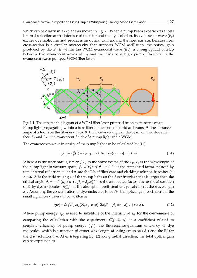
which can be drawn in XZ-plane as shown in Fig.I-1. When a pump beam experiences a total internal reflection at the interface of the fiber and the dye solution, its evanescent-wave (Ep) excites dye molecules and produces an optical gain around the fiber surface. Because fiber cross-section is a circular microcavity that supports WGM oscillation, the optical gain produced by the Ep is within the WGM evanescent-wave (Ew), a strong spatial overlap between two evanescent-waves of Ep and Ew leads to a high pump efficiency in the evanescent-wave pumped WGM fiber laser.
Fig. I-1. The schematic diagram of a WGM fiber laser pumped by an evanescent-wave.
Pump light propagating within a bare fiber in the form of meridian beams, i : the entrance
angle of a beam on the fiber end face, t: the incidence angle of the beam on the fiber side face, EP and Ew : the evanescent-fields of a pump light and a WGM.
The evanescence-wave intensity of the pump light can be calculated by [16]
20 1 2( ) ( ) exp[ 2 ( )( )]p pI r E r I k r a , (r ≥ a), (I-1)
Where a is the fiber radius, k = 2 / p is the wave vector of the Ep, p is the wavelength of
the pump light in vacuum space, 2 2 2 1/21 1 2[ sin ]tn n is the attenuated factor induced by
total internal reflection, n1 and n2 are the RIs of fiber core and cladding solution hereafter (n1
> n2), t is the incident angle of the pump light on the fiber interface that is larger than the
critical angle 12 1sin ( / )c n n , ,
2p out
p abs is the attenuated factor due to the absorption
of Ep by dye molecules, ,p outabs is the absorption coefficient of dye solution at the wavelength
p. Assuming the concentration of dye molecules to be N0, the optical gain coefficient in the
small signal condition can be written as
2 0 0 1 2( ) ( , , ) exp[ 2 ( )( )]c pg r C n N k r a , ( r a ). (I-2)
Where pump energy 0p is used to substitute of the intensity of 0I for the convenience of
comparing the calculation with the experiment, 2( , , )cC n is a coefficient related to
coupling efficiency of pump energy ( ), the fluorescence-quantum efficiency of dye
molecules, which is a function of center wavelength of lasing emission ( c ) and the RI for
the clad solution (n2). After integrating Eq. (2) along radial direction, the total optical gain can be expressed as
www.intechopen.com
Selected Topics on Optical Fiber Technology
198
G = 2 0 0 1 20
( ) ( , , ) exp[ 2 ( ) ]c pa
g r dr C n N k R dR
2 0 0
,1 22 2 21 2
( , , )
4 [( sin ) ]
c p p
p outt p abs
C n N
n n
. (I-3)
Since the pump-light source is usually a tightly focused laser beams [6, 9, 11], each beam
coupled into the fiber incidents upon the fiber side face with different angle t .
min
/22 2sin ( )sin
t
t t t tf d
is used to substitute the term of 2sin t in Eq. (3), where the mint is the minimum incident angle at fiber side face that relates to the maximum incident
angle maxi at fiber end face as shown in Fig.I-1, ( )tf is the distribution function of
incident angle that is defined as the fraction of pump intensity per unit angle. In order to get
the ( )tf , the intensity distribution of pump light on the fiber end face is assumed to be a
Gaussian function, 2 2 max0( ) exp[ tan tan ]i i iI I . The ( )tf thus can be expressed as
2 2 2 min
10 2 min 2 2
1
cos (1 cos )( ) exp[ ]
cos (1 cos )t t
tt t
nf f
n
, (I-4)
Where 0f is the normalized factor that can be calculated by the numeral integration. For the
purpose of comparison, a homogeneous distribution function ( )tf min1 /( /2 )t has
been used to calculate the term of 2sin t , the calculated optical gains for both distribution
functions are shown in Fig.I-2. Let 2sin t be equal to 2 maxsin t , the calculated gain curves
are also shown in Fig.I-2.
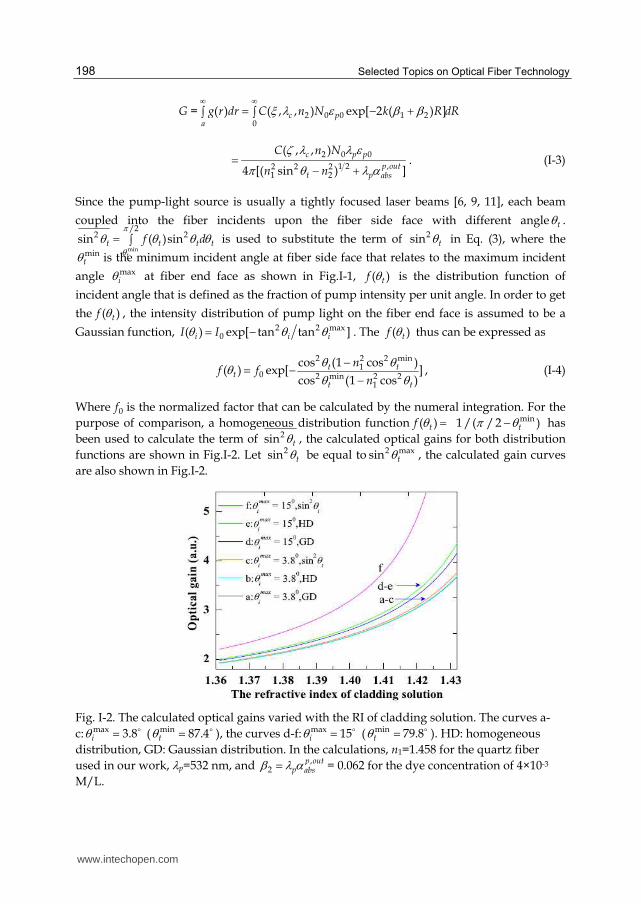
Fig. I-2. The calculated optical gains varied with the RI of cladding solution. The curves a-
c: max 3.8i ( min 87.4t ), the curves d-f: max 15i ( min 79.8t ). HD: homogeneous
distribution, GD: Gaussian distribution. In the calculations, n1=1.458 for the quartz fiber
used in our work, p=532 nm, and ,2
p outp abs = 0.062 for the dye concentration of 4×10⁻³
M/L.
www.intechopen.com
Evanescent-Wave Pumped and Gain Coupled Whispering-Gallery-Mode Fibre Laser
199
The calculations indicate that (1) the optical gain increases with the increase of n2 value and
the incident angle i , (2) when the incident angle i is small, the effect of distribution
function on the optical gain is not obvious, however, the effect can not be neglected with the
increase of the incident angle.
2.1.2 The cavity energy losses
Assuming the Qabs, Qleak and Qsca to be the quality factors of a circular cavity related to the
energy loss coefficients abs , leak and sca , which are caused by cavity absorption, light
leakage and scattering, respectively, the total quality factor (Qtol ) of a WGM in a cylindrical cavity can be expressed as
1 1 1 1
tol abs leak scatQ Q Q Q (I-5)
The absorption loss ( abs ) includes the losses inside the cavity ( ,w inabs , related to the inner
field of a WGM) and outside the cavity ( ,w outabs , related to the evanescent field of a WGM).
To calculate it, we assume an occupation factor ( w ) of a WGM in a circular cavity, which is
defined as the ratio of the evanescent-field volume to that of the whole WGM [1]. The
occupation factor can be written as2 2
0
( ) ( )wa
E r rdr E r rdr . For a TE wave in a
cylindrical coordinate system shown in the top left of Fig.I- 1, the EM field of a WGM in a cylindrical cavity can be written as [17] ,
1 1( ) ( )ln n zH r A J n k r e
, (0 ≤r ≤ a), (I-6a)
(1)2 2( ) ( )l
n n zH r A H n k r e , (r ≥ a), (I-6b)
'1 1 12
11
( ) ( ) ( )l
l lnn n r n n
knE r D J n k r e J n k r e
nn r
,(0 ≤ r ≤ a), (I-6c)
(1) (1)'2 2 22
22
( ) ( ) ( )l
l lnn n r n n
knE r D H n k r e H n k r e
nn r
,(r ≥ a). (I-6d)
Where A1, A2, D1 and D2 are constants; a is the radius of the cavity; nJ and (1)nH are the nth
Bessel and Hankel functions of the first kind, the derivative of the function denoted by a
prime is respect to its argument hereafter; 2 /l nn lk a is the wave vector in vacuum for
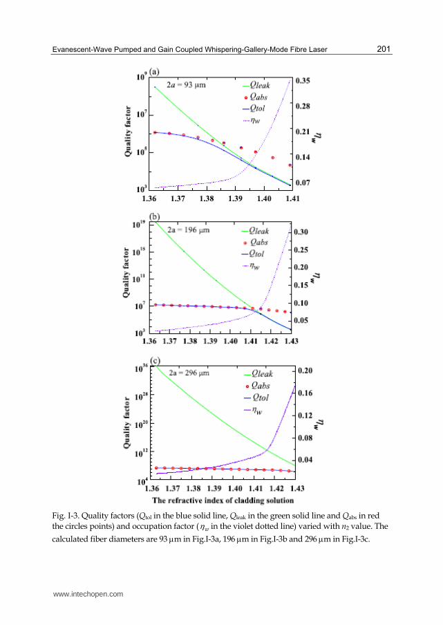
the nth angular mode number and lth radial mode order of a WGM. The occupation factors for (l, n) = (1,745), (1, 1530) and (1, 2256), which correspond to fiber diameters (2a = 93 1m, 196 1m and 296 1m) used in our work and the resonant wavelengths at 576.94, 583.14 and 583.72 nm, have been calculated as the function of n2 value, the calculated results are shown in Fig.I-3 as the violet dotted lines. The absorption coefficient
is , ,(1 ) w in w outabs w abs w abs , and the quality factor related to the abs thus can be written
as
www.intechopen.com
Selected Topics on Optical Fiber Technology
200
11 1( )abs in out
abs abs
QQ Q
, ,1
1 1
(1 )[ ]
2 2
w in n w out nabs l w abs l w
n n
. (I-7)
In the wavelength range of 560 to 580 nm, ,w inabs = 42 10 cm-1 in our calculation, ,w out
abs
=20.5 to 2.7 cm-1 for the dye concentration of 4×10⁻³ M/L, and 41.0 to 5.4 cm-1 for the
concentration 8×10⁻³ M/L. The calculated Qabs s varied with n2 value are shown in Fig.I-3 as
the red circular points. For the TE wave, there are two boundary conditions at surface (r = a) of a cylindrical cavity,
1 1( )ln nA J n k a = (1)
2 2( )ln nA H n k a and '1
11
( )ln n
DJ n k a
n= (1)'2
22
( )ln n
DH n k a
n, which can be deduced from
Eq. (6). As 1 2 2 1A D A D , the characteristic Eq.(6) for TE wave is written as
(1)' '1 2
2 1 (1)1 2
( ) ( )
( ) ( )
l ln n n n
l ln n n n
J n k a H n k an n
J n k a H n k a . (I-8)
Let ,l nx =2a/ nl be the size parameter of a circular cavity of radius a, based on Eq. (8) , the
Qleak for a TE wave of a WGM can be calculated with the analytic asymptotic formula [18] shown in Eq. (9).
'
2 2 ,(1)2 2 2 2 21 2 , 2 ,
1 , 2 ,
( )( ) ( ) ( ) ( ) .
4 ( )n l n
leak l n n l nl n n l n
Y n xnQ n n x H n x
n x Y n x
(I-9)
The Qleak s of (l, n) = (1,745), (1, 1530) and (1, 2256), have been calculated as the function of n2
value, the calculated results are shown in Fig.I- 3 as the green solid lines.
The value of scatQ is of the order of 1012 for an ultrahigh-Q microsphere with smooth surface
[19]. The scatQ s may be degraded to the order of 108 for the fibers used in our work, which
corresponds to a scattering loss scat 210-3 cm-1, and can be neglected by comparing with
abs that is in the range of 2 to 0.2 cm-1 within the wavelength range of 560 to 580 nm.
Therefore, 1 / 1 / 1 /tol abs leakQ Q Q , and the total cavity energy loss is expressed as
12 1 1
tol nabs leakl
n
Q Q
. (I-10)
The tolQ s have been calculated as the function of n2 value, the calculated results are shown
in Fig.I-3 as the blue solid lines. The calculated results indicate that (1) for the fiber with a larger diameter (Fig.I- 3c, 2a =
296 m), the Qleak is always much larger than the Qabs , the Qtol is determined mainly by the Qabs, as the result, the cavity loss increases smoothly with the n2 value; (2) for the fiber
with a small diameter (Fig.I- 3a , 2a = 93 m), as the n2 value increase, the Qtol is also determined by the Qabs if n2 is smaller than 1.385, however, the Qtol is determined mainly by the Qleak if n2 is larger than 1.385, which leads to a sharp increase of the cavity loss; (3)
for the fiber with a medium diameter (Fig.I- 3b, 2a = 196 m), the situation is between the cases (1) and (2).
www.intechopen.com
Evanescent-Wave Pumped and Gain Coupled Whispering-Gallery-Mode Fibre Laser
201
Fig. I-3. Quality factors (Qtol in the blue solid line, Qleak in the green solid line and Qabs in red
the circles points) and occupation factor ( w in the violet dotted line) varied with n2 value. The
calculated fiber diameters are 93 m in Fig.I-3a, 196 m in Fig.I-3b and 296 m in Fig.I-3c.
www.intechopen.com
Selected Topics on Optical Fiber Technology
202
2.1.3 The formulas of energy threshold and produced length of lasing emission
The threshold condition of lasing action is the gain equaling to the loss. Let Eq. (3) be equal to Eq. (10), the threshold energy can be expressed as
,1 22 2 21 2
02 0
4 [( sin ) ]
( , , )
p outt p absth
p tolc p
n n
C n N
,1 2' 2 2 22 1 2
0
( , , )[( sin ) ][ ]p outc t p abs leakabs
np l abs leak
C n n n Q Q
N Q Q
(I-11)
Due to the cladding solution is an absorption medium, the pump energy is gradually
attenuated along the fiber axis (Z-axis). The energy attenuation is consistent with Beer’s law,
0( ) exp( )pp p absZ Z , where p
abs is the absorption coefficient of pump light that consists
of two parts, the fiber absorption ( ,p inabs ) and the cladding’s absorption ( ,p out
abs ). Therefore,
the optical gain in Eq. (3) must be written as ( ) (0)exp( )pabsG Z G Z at the Z point. To
calculate the pabs value, similar to the definition of the abs for a WGM, we define an
occupation factor p for the pump light, which is the fraction of the evanescent-field
intensity to that of the whole pump light. The pabs is then written
as , ,(1 )p p in p outp pabs abs abs .
The produced length of lasing emission along the Z-axis increases with the pump energy
when the energy is larger than the threshold. For a given pump energy, there is a maximum
produced length maxZ , which corresponds to the optical gain at maxZ Z equaling to the
cavity loss, that is max( ) tolG Z . The threshold energy at the position maxZ Z is thus
written as 0 max 0 max( ) (0)exp( )pth thp p absZ Z , and the produced length of lasing emission along
the fiber axis can be expressed by the logarithmic function as
0 max 0
max , ,
ln[ ( )] ln[ (0)]
(1 )
th thp p
p in p outp pabs abs
ZZ
. (I-12)
Eqs. (11, 12) will be used to compare with the experimental results in Section 2.2.3 of this part.
2.2 Experimental results and discussion 2.2.1 Experimental setup
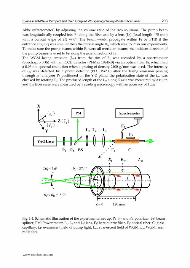
The experimental setup is shown in Fig.I-4 schematically. The laser beams (532.0 nm),
generated by a frequency doubled and Q-switched Nd:YAG laser, was used as a pump
light. The required pump energy was obtained by changing the polarization direction of a
polarizer (P1), and its power was monitored by a power meter (PM) through a beam splitter
(BS). The polarizer (P2) was used to determine the polarization state of the pump light. The
lenses L1 and L2 were used to compress the size of the pump beams. A bare fiber (F1,
RI=1.458) was inserted into a long glass capillary (C, 1 mm in inner diameter, 120 mm in
length), the open space between F1 and C was filled with ethanol and ethylene-glycol mixed
solution of the Rhodamine 6G dye with a concentration of 4×10⁻³ M/L. The RI of the mixed
solution, acting as the cladding solution, was varied from 1.361 to 1.430 (measured by an
www.intechopen.com
Evanescent-Wave Pumped and Gain Coupled Whispering-Gallery-Mode Fibre Laser
203
Abbe refractometer) by adjusting the volume ratio of the two solutions. The pump beam
was longitudinally coupled into F1 along the fiber axis by a lens (L3) (focal length =75 mm)
with a conical angle of 2i =7.6. The beam would propagate within F1 by FTIR if the
entrance angle i was smaller than the critical angle ic, which was 15.9 in our experiments.
To make sure the pump beams within F1 were all meridian beams, the incident direction of
the pump beams was set to be along the axial direction of F1.
The WGM lasing emission (Lw) from the rim of F1 was recorded by a spectrometer (Spectrapro 500i) with an ICCD detector (PI-Max 1024RB) via an optical fiber F2, which had a 0.05 nm spectral resolution when a grating of density 2400 g/mm was used. The intensity of Lw was detected by a photo detector (PD, DSi200) after the lasing emission passing through an analyzer P3 positioned on the Y-Z plane, the polarization state of the Lw was checked by rotating P3. The produced length of the Lw along Z-axis was measured by a ruler, and the fiber sizes were measured by a reading microscopy with an accuracy of 1μm.
2i = 7.6
i < ic =15.9
Ep EW LW
YAG Laser
PM
P1 P2 BS F1 C
Spectrometer
F2
Z (ze
)
Y
X
(re
)
( e
)
t = 87.4
L1 L2 L3 P3
Z = 0 120 mm
Fig. I-4. Schematic illustration of the experimental set up. P1 , P2 and P3: polarizer, BS: beam splitter, PM: Power meter, L1, L2 and L3: lens, F1: bare quartz fiber, F2: optical fiber, C: glass capillary, EP: evanescent field of pump light, Ew: evanescent field of WGM, Lw: WGM laser radiation.
www.intechopen.com
Selected Topics on Optical Fiber Technology
204
2.2.2 Experimental results
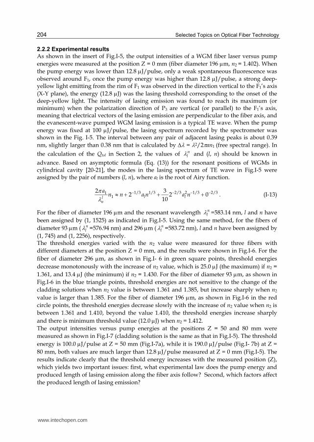
As shown in the insert of Fig.I-5, the output intensities of a WGM fiber laser versus pump
energies were measured at the position Z = 0 mm (fiber diameter 196 m, n2 = 1.402). When
the pump energy was lower than 12.8 J/pulse, only a weak spontaneous fluorescence was
observed around F1, once the pump energy was higher than 12.8 J/pulse, a strong deep-yellow light emitting from the rim of F1 was observed in the direction vertical to the F1’s axis
(X-Y plane), the energy (12.8 J) was the lasing threshold corresponding to the onset of the deep-yellow light. The intensity of lasing emission was found to reach its maximum (or minimum) when the polarization direction of P3 are vertical (or parallel) to the F1’s axis, meaning that electrical vectors of the lasing emission are perpendicular to the fiber axis, and the evanescent-wave pumped WGM lasing emission is a typical TE wave. When the pump
energy was fixed at 100 J/pulse, the lasing spectrum recorded by the spectrometer was shown in the Fig. I-5. The interval between any pair of adjacent lasing peaks is about 0.39
nm, slightly larger than 0.38 nm that is calculated by = 2/2an1 (free spectral range). In
the calculation of the Qtol in Section 2, the values of nl and (l, n) should be known in
advance. Based on asymptotic formula (Eq. (13)) for the resonant positions of WGMs in cylindrical cavity [20-21], the modes in the lasing spectrum of TE wave in Fig.I-5 were assigned by the pair of numbers (l, n), where al is the root of Airy function.
1/3 1/3 2/3 2 1/3 2/311
2 32 2 0
10l ll
n
an n a n a n
. (I-13)
For the fiber of diameter 196 m and the resonant wavelength nl =583.14 nm, l and n have
been assigned by (1, 1525) as indicated in Fig.I-5. Using the same method, for the fibers of
diameter 93 m ( nl =576.94 nm) and 296 m ( n
l =583.72 nm), l and n have been assigned by
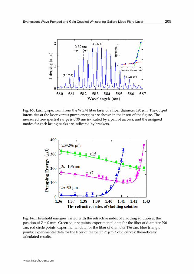
(1, 745) and (1, 2256), respectively. The threshold energies varied with the n2 value were measured for three fibers with
different diameters at the position Z = 0 mm, and the results were shown in Fig.I-6. For the
fiber of diameter 296 m, as shown in Fig.I- 6 in green square points, threshold energies
decrease monotonously with the increase of n2 value, which is 25.0 J (the maximum) if n2 =
1.361, and 13.4 J (the minimum) if n2 = 1.430. For the fiber of diameter 93 m, as shown in
Fig.I-6 in the blue triangle points, threshold energies are not sensitive to the change of the
cladding solutions when n2 value is between 1.361 and 1.385, but increase sharply when n2
value is larger than 1.385. For the fiber of diameter 196 m, as shown in Fig.I-6 in the red
circle points, the threshold energies decrease slowly with the increase of n2 value when n2 is
between 1.361 and 1.410, beyond the value 1.410, the threshold energies increase sharply
and there is minimum threshold value (12.0 J) when n2 = 1.412.
The output intensities versus pump energies at the positions Z = 50 and 80 mm were
measured as shown in Fig.I-7 (cladding solution is the same as that in Fig.I-5). The threshold
energy is 100.0 J/pulse at Z = 50 mm (Fig.I-7a), while it is 190.0 J/pulse (Fig.I- 7b) at Z =
80 mm, both values are much larger than 12.8 J/pulse measured at Z = 0 mm (Fig.I-5). The
results indicate clearly that the threshold energy increases with the measured position (Z),
which yields two important issues: first, what experimental law does the pump energy and
produced length of lasing emission along the fiber axis follow? Second, which factors affect
the produced length of lasing emission?
www.intechopen.com
Evanescent-Wave Pumped and Gain Coupled Whispering-Gallery-Mode Fibre Laser
205
Fig. I-5. Lasing spectrum from the WGM fiber laser of a fiber diameter 196 m. The output intensities of the laser versus pump energies are shown in the insert of the figure. The measured free spectral range is 0.39 nm indicated by a pair of arrows, and the assigned modes for each lasing peaks are indicated by brackets.
Fig. I-6. Threshold energies varied with the refractive index of cladding solution at the position of Z = 0 mm. Green square points: experimental data for the fiber of diameter 296
m, red circle points: experimental data for the fiber of diameter 196 m, blue triangle
points: experimental data for the fiber of diameter 93 m. Solid curves: theoretically calculated results.
www.intechopen.com
Selected Topics on Optical Fiber Technology
206
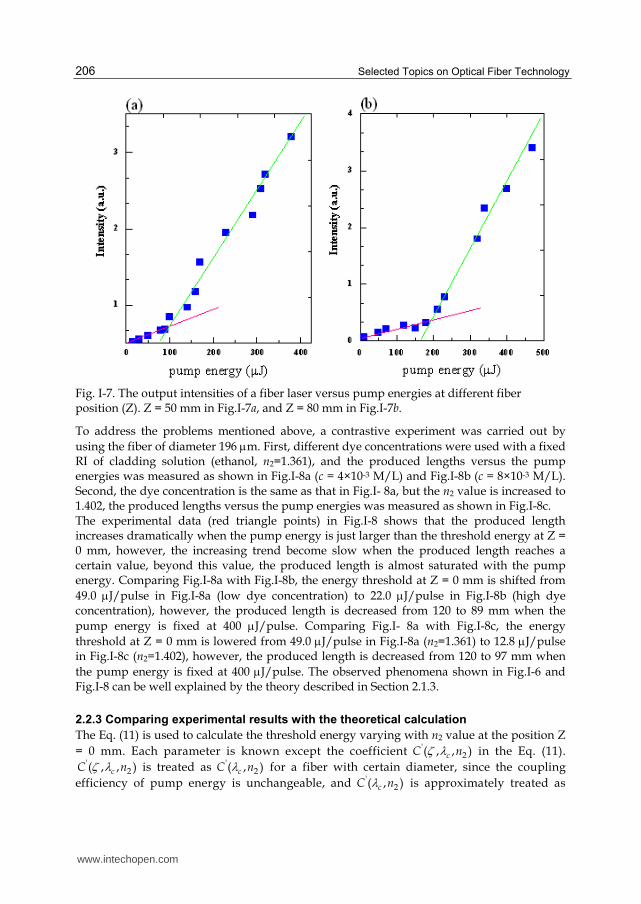
Fig. I-7. The output intensities of a fiber laser versus pump energies at different fiber position (Z). Z = 50 mm in Fig.I-7a, and Z = 80 mm in Fig.I-7b.
To address the problems mentioned above, a contrastive experiment was carried out by
using the fiber of diameter 196 m. First, different dye concentrations were used with a fixed RI of cladding solution (ethanol, n2=1.361), and the produced lengths versus the pump energies was measured as shown in Fig.I-8a (c = 4×10⁻³ M/L) and Fig.I-8b (c = 8×10⁻³ M/L). Second, the dye concentration is the same as that in Fig.I- 8a, but the n2 value is increased to 1.402, the produced lengths versus the pump energies was measured as shown in Fig.I-8c. The experimental data (red triangle points) in Fig.I-8 shows that the produced length increases dramatically when the pump energy is just larger than the threshold energy at Z = 0 mm, however, the increasing trend become slow when the produced length reaches a certain value, beyond this value, the produced length is almost saturated with the pump energy. Comparing Fig.I-8a with Fig.I-8b, the energy threshold at Z = 0 mm is shifted from
49.0 J/pulse in Fig.I-8a (low dye concentration) to 22.0 J/pulse in Fig.I-8b (high dye concentration), however, the produced length is decreased from 120 to 89 mm when the
pump energy is fixed at 400 J/pulse. Comparing Fig.I- 8a with Fig.I-8c, the energy
threshold at Z = 0 mm is lowered from 49.0 J/pulse in Fig.I-8a (n2=1.361) to 12.8 J/pulse in Fig.I-8c (n2=1.402), however, the produced length is decreased from 120 to 97 mm when
the pump energy is fixed at 400 J/pulse. The observed phenomena shown in Fig.I-6 and Fig.I-8 can be well explained by the theory described in Section 2.1.3.
2.2.3 Comparing experimental results with the theoretical calculation
The Eq. (11) is used to calculate the threshold energy varying with n2 value at the position Z
= 0 mm. Each parameter is known except the coefficient '2( , , )cC n in the Eq. (11).
'2( , , )cC n is treated as '
2( , )cC n for a fiber with certain diameter, since the coupling
efficiency of pump energy is unchangeable, and '2( , )cC n is approximately treated as
www.intechopen.com
Evanescent-Wave Pumped and Gain Coupled Whispering-Gallery-Mode Fibre Laser
207
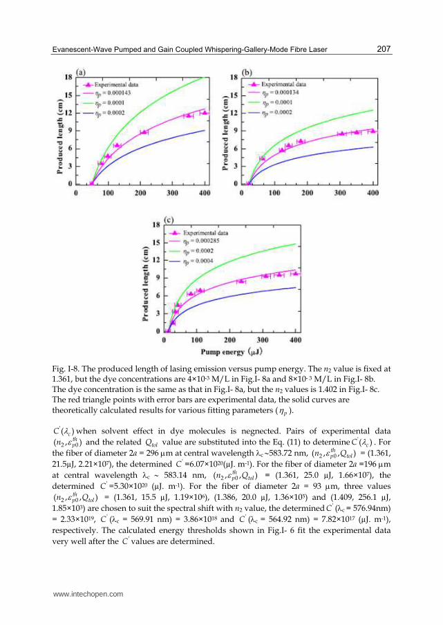
Fig. I-8. The produced length of lasing emission versus pump energy. The n2 value is fixed at 1.361, but the dye concentrations are 4×10⁻³ M/L in Fig.I- 8a and 8×10- 3 M/L in Fig.I- 8b. The dye concentration is the same as that in Fig.I- 8a, but the n2 values is 1.402 in Fig.I- 8c. The red triangle points with error bars are experimental data, the solid curves are
theoretically calculated results for various fitting parameters ( p ).
'( )cC when solvent effect in dye molecules is negnected. Pairs of experimental data
2 0( , )thpn and the related tolQ value are substituted into the Eq. (11) to determine '( )cC . For
the fiber of diameter 2a = 296 m at central wavelength c 583.72 nm, 2 0( , , )thp toln Q = (1.361,
21.5µJ, 2.21×10⁷), the determined 'C =6.07×10²⁰(µJ. m-1). For the fiber of diameter 2a =196 m
at central wavelength c 583.14 nm, 2 0( , , )thp toln Q = (1.361, 25.0 µJ, 1.66×10⁷), the
determined 'C =5.30×10²⁰ (µJ. m-1). For the fiber of diameter 2a = 93 m, three values
2 0( , , )thp toln Q = (1.361, 15.5 µJ, 1.19×10⁶), (1.386, 20.0 µJ, 1.36×10⁵) and (1.409, 256.1 µJ,
1.85×10³) are chosen to suit the spectral shift with n2 value, the determined 'C (c = 576.94nm)
= 2.33×10¹⁹, 'C (c = 569.91 nm) = 3.86×10¹⁸ and 'C (c = 564.92 nm) = 7.82×10¹⁷ (µJ. m-1),
respectively. The calculated energy thresholds shown in Fig.I- 6 fit the experimental data
very well after the 'C values are determined.
www.intechopen.com
Selected Topics on Optical Fiber Technology
208
The dependence of energy threshold on n2 value for the different fiber diameters can be understood when the properties of optical gain and cavity loss are considered simultaneously. Both optical gain and cavity loss increase with n2 value, the increment of energy threshold can be expressed by Eq. (11) as
0 2 2 2 2 2( ) ( ) ( ) ( ) ( )thp tol toln g n n g n n , (I-14)
where 2( )g n ,1 22 2 21 24 [( sin ) ]p out
t p absn n 0/ pCN is the factor related to optical gain. If
/ /tol tolg g /tol tolQ Q , that is the relative increment of optical gain being larger
than that of cavity loss, thus 0 2( ) 0thp n , otherwise 0 2( ) 0th
p n .
For the fiber of diameter 2a = 296 m, /g g is always larger than /tol tol
/tol tolQ Q when n2 varying from 1.361 to 1.430, thus 0 2( ) 0thp n , meaning that the
energy threshold decreases monotonously with the increase of n2 , which is shown in Fig.I- 6
as the green square points. For the fiber of diameter 2a = 93 m, /g g is slightly larger
than /tol tol when n2 varying from 1.361 to 1.385, thus 0 2( ) ~ 0thp n , meaning that the
increased optical gain compensates the increased cavity loss and the energy threshold keeps
stable; however, /g g << /tol tol after n2 > 1.385, thus 0 2( ) 0thp n , meaning that
more pump energy is required to compensate the cavity loss and the threshold energy
increases with the increase of n2 value, which is shown in Fig.I- 6 as the blue triangle points.
For the fiber of diameter 2a = 196 m, n2 =1.412 is a critical RI that corresponding to
/g g ~ /tol tol . When n2 < 1.412, /g g /tol tol , but /g g /tol tol when
n2 >1.412. Therefore, there is a minimum threshold energy at n2 =1.412, which is shown in
Fig.I- 6 as the red solid points.
Eq. (12) is used to calculate the produced length of lasing emission varied with pump
energy. Fiber absorption coefficient ( ,p inabs ) is 0.0002 cm-1, and the cladding absorption
( ,p outabs ) is 1156 cm-1 (2312 cm-1) at p =532 nm for dye concentration of 4×10⁻³ M/L(8×10-3
M/L). The occupation factor for pump light ( p ) is still an unknown value that is used as a
fitting parameter in Eq. (12), the p value for fitting the experimental data best is considered
as the true p . The fitting results are shown in Fig.I- 8. For the three experimental conditions
of (1) c = 4×10⁻³ M/L and n2 = 1.361 in Fig.I- 8a, (2) c = 8×10⁻³ M/L and n2 = 1.361 in Fig.I- 8b,
and (3) c = 4×10⁻³ M/L and n2=1.402 in Fig.I- 8c, Eq. (12) fits the experimental data best if
p = 1.43×10⁻⁴, 1.34×10⁻⁴, and 2.85×10⁻⁴, respectively. It is clear that the experimental data of
Zmax and max( )thp Z follow Eq. (12) well.
Comparing Fig.I- 8a with Fig.I- 8b in the same n2 value, a large dye concentration in Fig.I- 8b
will attenuate more evanescent field of the pump light, and reduce the penetration depth of
the pump light into the cladding solution, leading the p value to lower slightly down from
1.43×10⁻⁴ in Fig.I- 8a to 1.34×10⁻⁴ in Fig.I- 8b. Based on , ,(1 )p p in p outp pabs abs abs , the
calculated pabs values are 0.17 cm-1 in Fig.I- 8a and 0.31 cm-1 in Fig.I- 8b. A large absorption
coefficient pabs , of cause, will lead to a short produced length of lasing emission for a given
pump energy. The energy threshold at the position Z = 0 mm is determined mainly by the
dye concentration, the dye concentration in Fig.I- 8b is twice as that in Fig.I- 8a, therefore,
the energy threshold at Z = 0 mm is reduced from 49 (c = 4×10⁻³ M/L in Fig.I- 8a) to 22
J/pulse (c = 8×10⁻³M/L in Fig.I- 8b).
www.intechopen.com
Evanescent-Wave Pumped and Gain Coupled Whispering-Gallery-Mode Fibre Laser
209
Comparing Fig.I- 8a with Fig.I- 8c in the same dye concentration, a large n2 value in Fig.I- 8c
implies a long penetration depth of the pump light into the cladding solution, which leads
p value to rise up from 1.43×10⁻⁴ in Fig.I- 8a to 2.85×10⁻⁴ in Fig.I- 8c, corresponding pabs
values to increase from 0.17 cm-1 to 0.33 cm-1. Based on Eq. (12), the produced length of
lasing emission in Fig.I- 8c will be shorter than that of Fig.I- 8a for a given pump energy. The
energy threshold at the position Z = 0 mm is determined mainly by n2 value at this time, a
large n2 value implies a long penetration depth of pump light into cladding solution, and
thus a large occupation factor p . When p value increasing from 1.43×10⁻⁴ in Fig.I-8a
(n2=1.361) to 2.85×10⁻⁴ in Fig.I-8c (n2=1.402), more dye molecules are excited by the given
pump energy, it is reasonable that the energy threshold is reduced from 49 to 12.8 J/pulse.
3. Part II - Polarization properties of an evanescent-wave pumped Whispering-Gallery-Mode fibre laser
In Part II, the polarization properties of an evanescent-wave pumped Whispering Gallery
Mode (WGM) fibre laser evanescent-wave pumping scheme are investigated. The dye gain
is produced by the evanescent field of the pump light, therefore, the polarization state of the
evanescent field determines the vibration states of excited molecules, consequently the
polarization properties of lasing emission of the evanescent-wave pumped WGM fibre laser.
We find that when the pump beam is strictly along the axial direction of an optical fibre, the
lasing emission is transverse electric (TE) wave and the electrical vector of emitting point is
along the radial direction of the optical fibre, which forms a special radial polarized
radiation; while the pump beam deviates from the axial direction of the optical fibre, both
TE and transverse magnetic (TM) waves exist in the lasing emission, which forms a mixed
polarization radiation with radial and axial polarized states. The radial polarization laser is
useful in the application of photo-etching [22] and high resolution microscope [23], etc. We
report on our experimental results and give the explanation for observed phenomenon in
this part.
3.1 Experimental setup
The experiment setup is shown in Fig.II-1. A pulsed Nd:YAG laser (=532 nm, pulse
width=7 ns) is used as a pump source. The pump laser beams pass two polarizers P1 and P2.
P2 is used to determine polarized state of the pump beams, while P1 is used to change pump
energy by rotating its polarization direction. Lenses L1 and L2 are used to shrink the pump
beams size from original 8 mm to 1.5 mm. F1 of diameter 196 m is a barely optical fibre
with the refractive index of 1.458. After being focused by lens L3 (focal length =75 mm), the
pump beams are end-fired into F1 with an incident angle i =1.2. To make sure the pump
light is meridian beams [15] when propagating in F1, the axis of F1 is adjusted strictly along
the z-axis. The pump light will be skew beams [15] in F1 when the angle between the axis of
F1 and the z-axis is about 10. The fibre F1 is inserted into a glass tube D with the inner diameter of 2 mm. A mixed solution of ethanol and ethylene glycol doped with Rhodamine 6G dye molecules is filled into the glass tube, and the concentration and refractive index of the dye solution are 3×10⁻³
mol/L and 1.422, respectively. The pump beams will propagate within F1 by TIR if the
incident angle i is smaller than 37.6. Evanescent field Ep of the pump beams excite the dye
www.intechopen.com
Selected Topics on Optical Fiber Technology
210
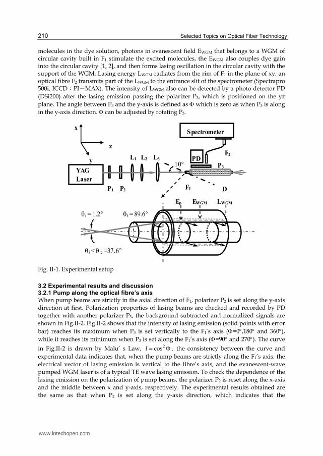
molecules in the dye solution, photons in evanescent field EWGM that belongs to a WGM of circular cavity built in F1 stimulate the excited molecules, the EWGM also couples dye gain into the circular cavity [1, 2], and then forms lasing oscillation in the circular cavity with the support of the WGM. Lasing energy LWGM radiates from the rim of F1 in the plane of xy, an optical fibre F2 transmits part of the LWGM to the entrance slit of the spectrometer (Spectrapro 500i, ICCD:PI-MAX). The intensity of LWGM also can be detected by a photo detector PD
(DSi200) after the lasing emission passing the polarizer P3, which is positioned on the yz
plane. The angle between P3 and the y-axis is defined as which is zero as when P3 is along
in the y-axis direction. can be adjusted by rotating P3.
i = 1.2
i < ic =37.6
Ep EWGM LWGM
YAG
Laser
P1 P2
Spectrometer
L1 L2 L3
z
y
x
t = 89.6
PD10
F1 D
F2
P3
Fig. II-1. Experimental setup
3.2 Experimental results and discussion 3.2.1 Pump along the optical fibre’s axis
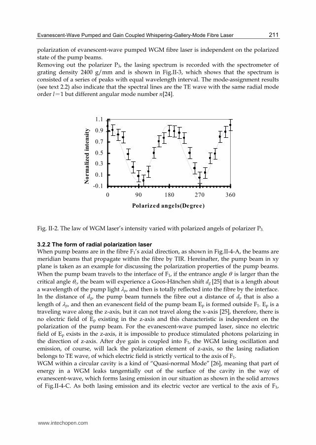
When pump beams are strictly in the axial direction of F1, polarizer P2 is set along the y-axis
direction at first. Polarization properties of lasing beams are checked and recorded by PD
together with another polarizer P3, the background subtracted and normalized signals are
shown in Fig.II-2. Fig.II-2 shows that the intensity of lasing emission (solid points with error
bar) reaches its maximum when P3 is set vertically to the F1’s axis (=0,180 and 360), while it reaches its minimum when P3 is set along the F1’s axis (=90 and 270). The curve
in Fig.II-2 is drawn by Malu’ s Law, 2cosI , the consistency between the curve and
experimental data indicates that, when the pump beams are strictly along the F1’s axis, the
electrical vector of lasing emission is vertical to the fibre’s axis, and the evanescent-wave
pumped WGM laser is of a typical TE wave lasing emission. To check the dependence of the
lasing emission on the polarization of pump beams, the polarizer P2 is reset along the x-axis
and the middle between x and y-axis, respectively. The experimental results obtained are
the same as that when P2 is set along the y-axis direction, which indicates that the
www.intechopen.com
Evanescent-Wave Pumped and Gain Coupled Whispering-Gallery-Mode Fibre Laser
211
polarization of evanescent-wave pumped WGM fibre laser is independent on the polarized
state of the pump beams.
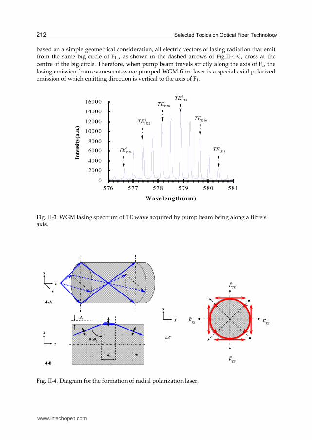
Removing out the polarizer P3, the lasing spectrum is recorded with the spectrometer of grating density 2400 g/mm and is shown in Fig.II-3, which shows that the spectrum is consisted of a series of peaks with equal wavelength interval. The mode-assignment results (see text 2.2) also indicate that the spectral lines are the TE wave with the same radial mode order l=1 but different angular mode number n[24].
-0.1
0.1
0.3
0.5
0.7
0.9
1.1
0 90 180 270 360
Polarized angels(Degree)
No
rm
ali
zed
in
ten
sity
Fig. II-2. The law of WGM laser’s intensity varied with polarized angels of polarizer P3.
3.2.2 The form of radial polarization laser
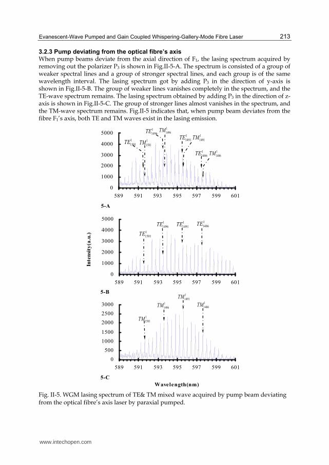
When pump beams are in the fibre F1’s axial direction, as shown in Fig.II-4-A, the beams are meridian beams that propagate within the fibre by TIR. Hereinafter, the pump beam in xy plane is taken as an example for discussing the polarization properties of the pump beams.
When the pump beam travels to the interface of F1, if the entrance angle is larger than the
critical angle c, the beam will experience a Goos-Hänchen shift dg [25] that is a length about
a wavelength of the pump light p, and then is totally reflected into the fibre by the interface. In the distance of dg, the pump beam tunnels the fibre out a distance of dp that is also a
length of p, and then an evanescent field of the pump beam Ep is formed outside F1. Ep is a traveling wave along the z-axis, but it can not travel along the x-axis [25], therefore, there is no electric field of Ep existing in the z-axis and this characteristic is independent on the polarization of the pump beam. For the evanescent-wave pumped laser, since no electric field of Ep exists in the z-axis, it is impossible to produce stimulated photons polarizing in the direction of z-axis. After dye gain is coupled into F1, the WGM lasing oscillation and emission, of course, will lack the polarization element of z-axis, so the lasing radiation belongs to TE wave, of which electric field is strictly vertical to the axis of F1. WGM within a circular cavity is a kind of “Quasi-normal Mode” [26], meaning that part of
energy in a WGM leaks tangentially out of the surface of the cavity in the way of
evanescent-wave, which forms lasing emission in our situation as shown in the solid arrows
of Fig.II-4-C. As both lasing emission and its electric vector are vertical to the axis of F1,
www.intechopen.com
Selected Topics on Optical Fiber Technology
212
based on a simple geometrical consideration, all electric vectors of lasing radiation that emit
from the same big circle of F1 , as shown in the dashed arrows of Fig.II-4-C, cross at the
centre of the big circle. Therefore, when pump beam travels strictly along the axis of F1, the
lasing emission from evanescent-wave pumped WGM fibre laser is a special axial polarized
emission of which emitting direction is vertical to the axis of F1.
0
2000
4000
6000
8000
10000
12000
14000
16000
576 577 578 579 580 581
Wavelength(nm)
Inte
nsi
ty(a
.u.)
1
1522TE
1
1520TE
1
1518TE
1
1514TE
1
1516TE
1
1524TE
Fig. II-3. WGM lasing spectrum of TE wave acquired by pump beam being along a fibre’s axis.
x
z
y
4-A
> c
x
z
dg
dp
n1
4-B
TEE
TEE
TEE
TEE
x
y
4-C
Fig. II-4. Diagram for the formation of radial polarization laser.
www.intechopen.com
Evanescent-Wave Pumped and Gain Coupled Whispering-Gallery-Mode Fibre Laser
213
3.2.3 Pump deviating from the optical fibre’s axis When pump beams deviate from the axial direction of F1, the lasing spectrum acquired by removing out the polarizer P3 is shown in Fig.II-5-A. The spectrum is consisted of a group of weaker spectral lines and a group of stronger spectral lines, and each group is of the same wavelength interval. The lasing spectrum got by adding P3 in the direction of y-axis is shown in Fig.II-5-B. The group of weaker lines vanishes completely in the spectrum, and the TE-wave spectrum remains. The lasing spectrum obtained by adding P3 in the direction of z-axis is shown in Fig.II-5-C. The group of stronger lines almost vanishes in the spectrum, and the TM-wave spectrum remains. Fig.II-5 indicates that, when pump beam deviates from the fibre F1’s axis, both TE and TM waves exist in the lasing emission.
0
1000
2000
3000
4000
5000
589 591 593 595 597 599 601
1
1486TM
1
1491TE
1
1496TM
1
1501TM1
1501TE
1
1491TM
1
1486TE
1
1496TE
5-A
0
1000
2000
3000
4000
5000
589 591 593 595 597 599 601
Inte
nsi
ty(a
.u.)
5-B
1
1501TE
1
1496TE1
1491TE1
1486TE
0
500
1000
1500
2000
2500
3000
589 591 593 595 597 599 601
Wavelength(nm)
1
1501TM
1
1496TM
1
1491TM
1
1486TM
5-C
Fig. II-5. WGM lasing spectrum of TE& TM mixed wave acquired by pump beam deviating from the optical fibre’s axis laser by paraxial pumped.
www.intechopen.com
Selected Topics on Optical Fiber Technology
214
x
z
y
k
//k
k
x
y > c
//k
x
y
TETMEE
TETMEE
TE
TM
E
E
TE
TM
E
E
6-A
6-B
6-C
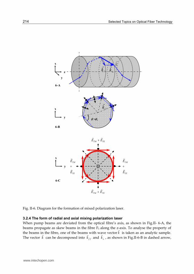
Fig. II-6. Diagram for the formation of mixed polarization laser.
3.2.4 The form of radial and axial mixing polarization laser
When pump beams are deviated from the optical fibre’s axis, as shown in Fig.II- 6-A, the
beams propagate as skew beams in the fibre F1 along the z-axis. To analyse the property of
the beams in the fibre, one of the beams with wave vector k
is taken as an analytic sample.
The vector k
can be decomposed into //k
and k
, as shown in Fig.II-6-B in dashed arrow,
www.intechopen.com
Evanescent-Wave Pumped and Gain Coupled Whispering-Gallery-Mode Fibre Laser
215
//k
is a component that expresses a light beam propagating in the xy plane by TIR; while
k
is a component that expresses a light beam propagating along the z-axis. For the beam
expressed by //k
, both electric vectors, the vector being parallel to z-axis and the vector
being vertical to z-axis, exist simultaneously in the fibre F1, when the beam experiences TIR
on the fibre’s interface, as shown in Fig.II-6-B, both electric vectors also exist in the
evanescent field of pump beam. Because the dye molecules in the evanescent field of pump
beam are excited by two different electric vectors, two kinds of stimulated photons,
polarizing in the z-axis and in the xy plane, therefore, exist simultaneously in the evanescent
field of WGMs of the circular cavity built in the optical fibre F1. After the dye gain is coupled
into the circular cavity, the WGM lasing oscillation and emission, of course, contain TE
wave that is polarizing in the xy plane and TM wave that is polarizing along the z-axis.
Combining with the analysis at the end part of this text 2.2, as shown in Fig.II-6-C, it can be
conluded that the electric field of TE wave crosses at the centre of the circular cavity, while
the electric field of TM wave is parallel to the z-axis; when pump beams are deviated from
the axis of the optical fibre, the lasing emission from evanescent-wave pumped WGM fibre
laser is a mixed polarization emission.
4. Part III - Linearly polarized three-color lasing emission from an evanescent wave pumped and gain coupled fibre laser
In Part III, an evanescent-wave pumped and gain coupled WGM fiber laser is introduced by
inserting a bare quartz fiber (no cladding layer) into a glass capillary filled with dye
molecules in a lower refractive index solution. Once the bare fiber is inserted into three glass
capillaries filled with Rhodamine 6G, Rhodamine 610 and Rhodamine 640 dye solutions,
respectively, WGM laser oscillations at the wavelengths of 567-575, 605-614 and 656-666 nm
occur simultaneously, and a linearly polarized three-color lasing emission is achieved in a
single optical fiber.
4.1 Experimental setup
The experimental setup is shown in Fig.I-4 schematically. An bare fiber (F1, 1961 m in diameter, refractive index 1.458) was inserted into a long glass capillary (C, 1 mm in inner diameter), the residual space between F1 and C was filled with ethanol and ethylene-glycol mixed solution doped by Rhodamine 6G dye with a concentration of 3×10⁻³ M/L. The refractive index of the mixed solution, acting as the cladding solution of F1, was 1.395 measured by an Abbe refractometer. The pump beam was longitudinally coupled into F1
along the fiber’s axis by a lens (L) (focal length =75 mm) with a conical angle of i =9.2. The
beam would propagate within F1 by TIR if the conical angle i was smaller than the critical
entrance angle ic, which was 35.6 in our experiments. The evanescent field of the pump light (Ep) excites dye molecules in the mixed solution, thus the photons in evanescent field of WGM (EWGM) of a circular cavity stimulate the excited dye molecules, and the EWGM also couples dye gain into the circular cavity at the same time. Supported by the WGMs, lasing oscillations occur in the circular cavity. The WGM lasing emission (LWGM) from the rim of F1 can be recorded by a spectrometer (Spectrapro 500i) equipped with an ICCD detector (PI-Max 1024RB) via an optical fiber F2, it gives 0.05 nm spectral resolution when a grating of density 2400g/mm is used. The intensity of LWGM is
www.intechopen.com
Selected Topics on Optical Fiber Technology
216
detected by a photo detector (PD, DSi200) after the lasing emission passing through an analyzer P3 positioned on the yz plane.
4.2 Experimental results and discussion 4.2.1 Three-color WGM lasing emission
It is found that the generating length of lasing emission along the F1 increases with pumping
energy by arranging pump configuration as described in the part I, in which the fiber F1 was
replaced by a thick fiber (288 m in diameter) and the direction of the incident beam was
still strictly along the axial direction of F1. When the pumping energy equaled 20, 50 and 100
J/pulse, the lengths of the lasing emission were 40, 90 mm and over 120 mm, respectively.
Based on this, a longer gain length in evanescent-wave pumped WGM fiber laser, of course,
can be utilized to build a multicolor WGM fiber laser [27]. That is to say, the fiber F1 was
inserted into three short glass capillaries (15 mm long) in series and their intervals between
the capillaries were 5 mm. Rhodamine 6G, Rhodamine 610 and Rhodamine 640 dye
molecules were dissolved in ethanol and ethylene-glycol mixed solution to obtain
concentrations 510-4, 210-3 and 110-2 M/L, respectively. The prepared dye solutions with
an index of 1.422 were filled in the residual space between the F1 and the capillaries.
Evanescently pumped by 532 nm line of the pulsed YAG laser along the fiber’s axis, only a
weak fluorescent light emitted out from the fiber when the pumping energy was 20
J/pulse. The fluorescent spectrum was recorded by a spectrometer with a grating of
density 150g/mm, which is the grey curve shown in Fig. III-1A. When pumping energy was
80 J/pulse, we observed three-color (yellow, orange and red) WGM lasing emissions
simultaneously in experiments, the emitting wavelengths from the fiber laser were in the
ranges of 567-575 nm (Rhodamine 6G), 605-614 nm (Rhodamine 610) and 656-666 nm
(Rhodamine 640) as shown in Fig. III-1A with the black curve. Since three-color WGM lasing
emission from a single optical fiber was realized, a novel evanescent-wave pumped and
gain coupled WGM fiber multicolor laser was demonstrated eventually.
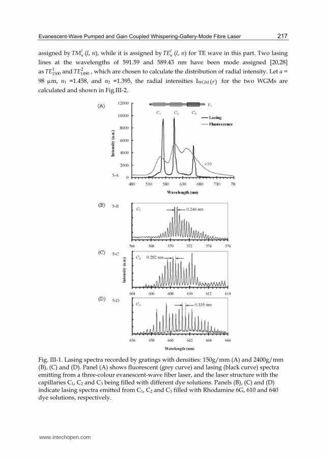
To show the fine spectral structure of the three-color WGM lasing emission, the spectra were
recorded with a grating of density 2400g/mm, and shown in Figs. III-1B, 1C, and 1D in the
wavelengths 567-575 nm, 605-614 nm and 656-666 nm, respectively. The measured spectral
intervals between two adjacent peaks are 0.246 nm (Fig.III-1B), 0.282 nm (Fig.III-1C) and
0.335 nm (Fig.III-1D), which can be compared with the calculated free spectral widths of
WGMs in the used circular cavity. For a larger diameter fiber (288 m in our case), the
wavelength intervals (free spectral width) can be approximately calculated by [27] = 2/2an1, where a and n1 are the radius and the refractive index of the used fiber,
respectively. The calculated wavelength intervals are 0.247, 0.281 and 0.332 nm in the
wavelength ranges of 567-575 nm, 605-614 nm and 656-666 nm, which accord well with the
measured values.
4.2.2 Spacial overlap between evanescent wave of WGM and lasing gain
To explain the characteristic of the longer gain in an evanescent-wave pumped WGM fiber laser, the radial intensities of the WGMs in the used circular cavity and the evanescent field of pump light are calculated. For a TE wave in a cylindrical coordinate system shown in the top left of Fig.I-4, the electric field of a WGM in a cylindrical cavity can be written as (I-6c, 6d). For TM wave with radial mode number l and angular mode number n, the WGM is
www.intechopen.com
Evanescent-Wave Pumped and Gain Coupled Whispering-Gallery-Mode Fibre Laser
217
assigned by lnTM (l, n), while it is assigned by l
nTE (l, n) for TE wave in this part. Two lasing
lines at the wavelengths of 591.59 and 589.43 nm have been mode assigned [20,28]
as 11500TE and 2
1490TE , which are chosen to calculate the distribution of radial intensity. Let a =
98 m, n1 =1.458, and n2 =1.395, the radial intensities IWGM ( )r for the two WGMs are
calculated and shown in Fig.III-2.
Fig. III-1. Lasing spectra recorded by gratings with densities: 150g/mm (A) and 2400g/mm (B), (C) and (D). Panel (A) shows fluorescent (grey curve) and lasing (black curve) spectra emitting from a three-colour evanescent-wave fiber laser, and the laser structure with the capillaries C1, C2 and C3 being filled with different dye solutions. Panels (B), (C) and (D) indicate lasing spectra emitted from C1, C2 and C3 filled with Rhodamine 6G, 610 and 640 dye solutions, respectively.
www.intechopen.com
Selected Topics on Optical Fiber Technology
218
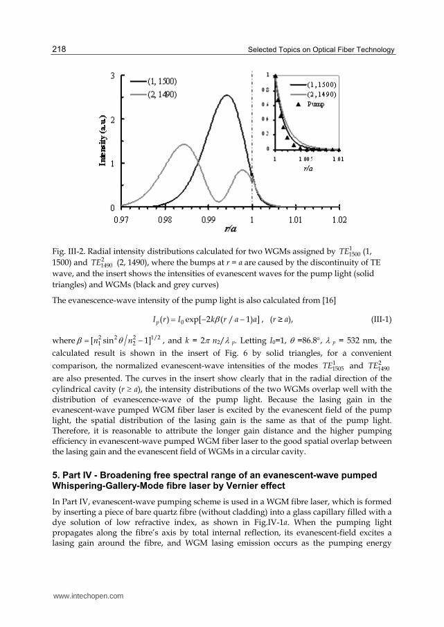
Fig. III-2. Radial intensity distributions calculated for two WGMs assigned by 11500TE (1,
1500) and 21490TE (2, 1490), where the bumps at r = a are caused by the discontinuity of TE
wave, and the insert shows the intensities of evanescent waves for the pump light (solid
triangles) and WGMs (black and grey curves)
The evanescence-wave intensity of the pump light is also calculated from [16]
0( ) exp[ 2 ( / 1) ]pI r I k r a a , (r ≥ a), (III-1)
where 2 2 2 1/21 2[ sin 1]n n , and k = 2 n2/ p. Letting I0=1, =86.8, p = 532 nm, the
calculated result is shown in the insert of Fig. 6 by solid triangles, for a convenient
comparison, the normalized evanescent-wave intensities of the modes 11505TE and 2
1490TE
are also presented. The curves in the insert show clearly that in the radial direction of the
cylindrical cavity (r a), the intensity distributions of the two WGMs overlap well with the distribution of evanescence-wave of the pump light. Because the lasing gain in the evanescent-wave pumped WGM fiber laser is excited by the evanescent field of the pump light, the spatial distribution of the lasing gain is the same as that of the pump light. Therefore, it is reasonable to attribute the longer gain distance and the higher pumping efficiency in evanescent-wave pumped WGM fiber laser to the good spatial overlap between the lasing gain and the evanescent field of WGMs in a circular cavity.
5. Part IV - Broadening free spectral range of an evanescent-wave pumped Whispering-Gallery-Mode fibre laser by Vernier effect
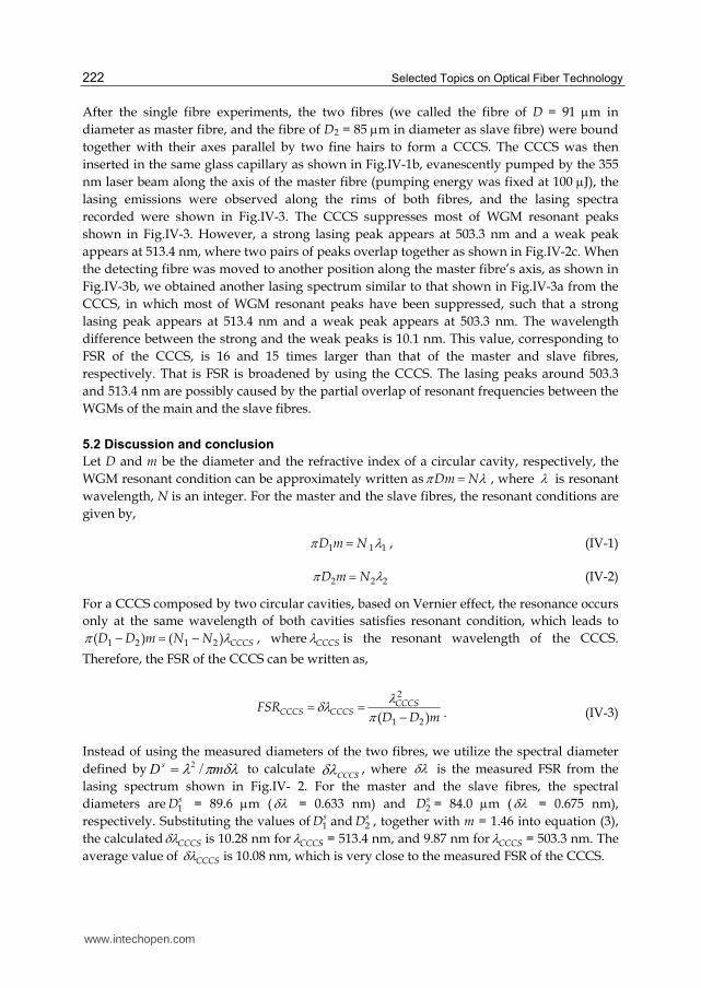
In Part IV, evanescent-wave pumping scheme is used in a WGM fibre laser, which is formed by inserting a piece of bare quartz fibre (without cladding) into a glass capillary filled with a dye solution of low refractive index, as shown in Fig.IV-1a. When the pumping light propagates along the fibre’s axis by total internal reflection, its evanescent-field excites a lasing gain around the fibre, and WGM lasing emission occurs as the pumping energy
www.intechopen.com
Evanescent-Wave Pumped and Gain Coupled Whispering-Gallery-Mode Fibre Laser
219
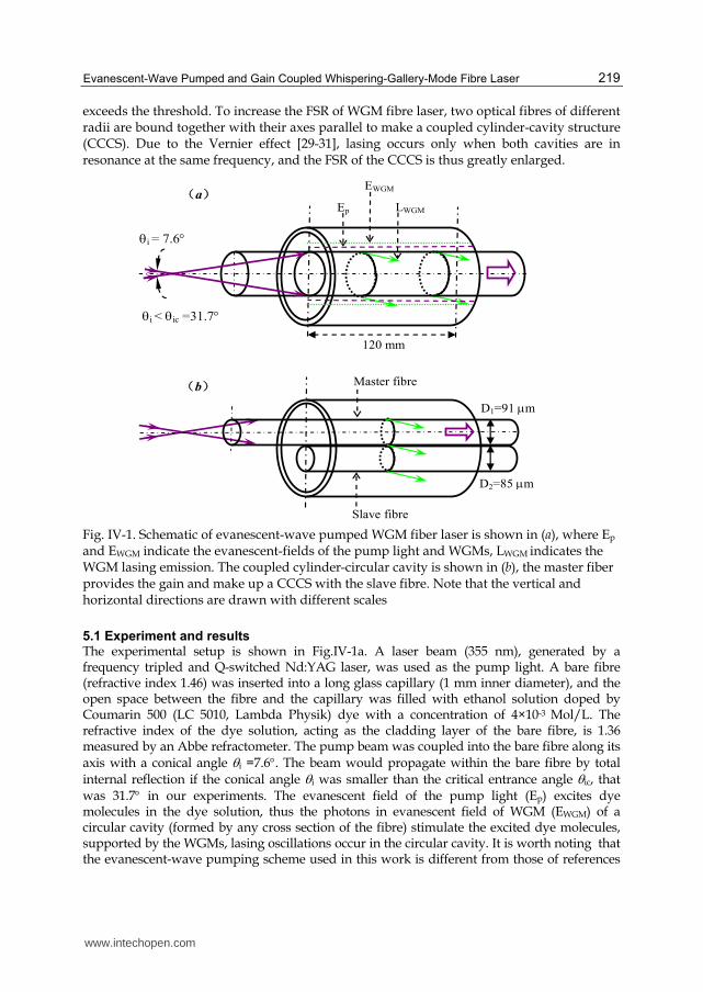
exceeds the threshold. To increase the FSR of WGM fibre laser, two optical fibres of different radii are bound together with their axes parallel to make a coupled cylinder-cavity structure (CCCS). Due to the Vernier effect [29-31], lasing occurs only when both cavities are in resonance at the same frequency, and the FSR of the CCCS is thus greatly enlarged.
D1=91 m
D2=85 m
Slave fibre
Master fibre ′b″
LWGM
i = 7.6
i < ic =31.7
Ep
EWGM
120 mm
′a″
Fig. IV-1. Schematic of evanescent-wave pumped WGM fiber laser is shown in (a), where Ep
and EWGM indicate the evanescent-fields of the pump light and WGMs, LWGM indicates the WGM lasing emission. The coupled cylinder-circular cavity is shown in (b), the master fiber provides the gain and make up a CCCS with the slave fibre. Note that the vertical and horizontal directions are drawn with different scales
5.1 Experiment and results The experimental setup is shown in Fig.IV-1a. A laser beam (355 nm), generated by a frequency tripled and Q-switched Nd:YAG laser, was used as the pump light. A bare fibre (refractive index 1.46) was inserted into a long glass capillary (1 mm inner diameter), and the open space between the fibre and the capillary was filled with ethanol solution doped by Coumarin 500 (LC 5010, Lambda Physik) dye with a concentration of 4×10⁻³ Mol/L. The refractive index of the dye solution, acting as the cladding layer of the bare fibre, is 1.36 measured by an Abbe refractometer. The pump beam was coupled into the bare fibre along its axis with a conical angle i =7.6. The beam would propagate within the bare fibre by total internal reflection if the conical angle i was smaller than the critical entrance angle ic, that was 31.7 in our experiments. The evanescent field of the pump light (Ep) excites dye molecules in the dye solution, thus the photons in evanescent field of WGM (EWGM) of a circular cavity (formed by any cross section of the fibre) stimulate the excited dye molecules, supported by the WGMs, lasing oscillations occur in the circular cavity. It is worth noting that the evanescent-wave pumping scheme used in this work is different from those of references
www.intechopen.com
Selected Topics on Optical Fiber Technology
220
[30] and [31]. The ring cavity in reference [30] is composed by gain material and the gain is obtained by directly pumping the cavity, while the side-pumping scheme is used in reference [31]. The WGM lasing emission (LWGM) from the rim of the fibre can be recorded via a detecting fibre by a spectrometer (Spectrapro 500i) equipped with a CCD detector (PI-Max 1024RB), which gives 0.05 nm spectral resolution when a grating of density 2400g/mm is used.
0
2000
4000
6000
8000
501 504 507 510 513 516 519
Wavelength/nm
Inte
nsi
ty/a
.u.
D1 = 91 m 0.633 nm
(a )
0
2000
4000
6000
500 503 506 509 512 515 518
Wavelength/nm
Inte
nsi
ty/a
.u.
D2 = 85 m
0.675 nm
(b )
0
2000
4000
6000
8000
502 505 508 511 514 517
Wavelength/nm
Inte
nsi
ty/a
.u.
513.4 nm D1 = 91 m
D2 = 85 m
503.3 nm
(c )
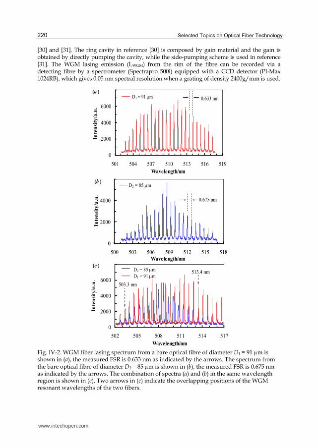
Fig. IV-2. WGM fiber lasing spectrum from a bare optical fibre of diameter D1 = 91 m is shown in (a), the measured FSR is 0.633 nm as indicated by the arrows. The spectrum from the bare optical fibre of diameter D2 = 85 m is shown in (b), the measured FSR is 0.675 nm as indicated by the arrows. The combination of spectra (a) and (b) in the same wavelength region is shown in (c). Two arrows in (c) indicate the overlapping positions of the WGM resonant wavelengths of the two fibers.
www.intechopen.com
Evanescent-Wave Pumped and Gain Coupled Whispering-Gallery-Mode Fibre Laser
221
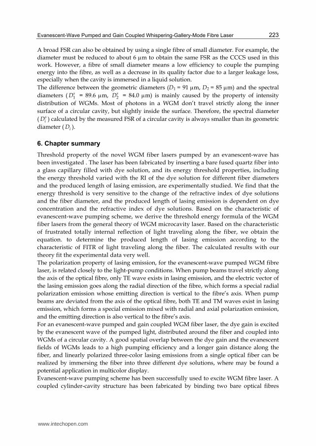
Two types of fibres with diameter D1 = 91 m and D2 = 85 m, measured by a microscope
with 1 m uncertainty, were prepared by etching two bare quartz fibres of original diameter
100 m in a diluted HF-acid solution. After supersonic cleaning in ethanol, one of the fibres was inserted in the glass capillary filled with ethanol dye solution. The fibre was evanescently pumped by the 355 nm laser beam along its axis, and WGM lasing spectra
were investigated. For the fibre with a diameter D1 = 91 m (D2 = 85 m), lasing emission
was observed when the pumping energy was larger than 25 J (30 J), and the lasing spectrum was recorded as shown in Fig.IV-2a (Fig.IV- 2b) with the pumping energy fixed at
100 J. The measured average FSR in the spectral range from 504 to 516 nm was 0.633 nm for
the fibre of D1 = 91 m, while it was 0.675 nm in the spectral range from 506 to 513 nm for
the fibre of D2 = 85 m. When the two spectra (Fig.IV-2a and 2b) are merged together in the same wavelength region, as shown in Fig.IV-2c, it is found that two pairs of peaks corresponding to WGM resonant wavelengths overlap, and the overlapping wavelengths are 503.3 nm and 513.4 nm as indicated in Fig.IV-2c by the dashed arrows.
0
2000
4000
6000
8000
502 505 508 511 514 517
Wavelength/nm
Inte
nsi
ty/a
.u.
CCCS-A503.3 nm
513.4 nm
(a )
0
2000
4000
6000
8000
10000
502 505 508 511 514 517
Wavelength/nm
Inte
nsi
ty/a
.u.
CCCS-B
503.3 nm
513.4 nm(b )
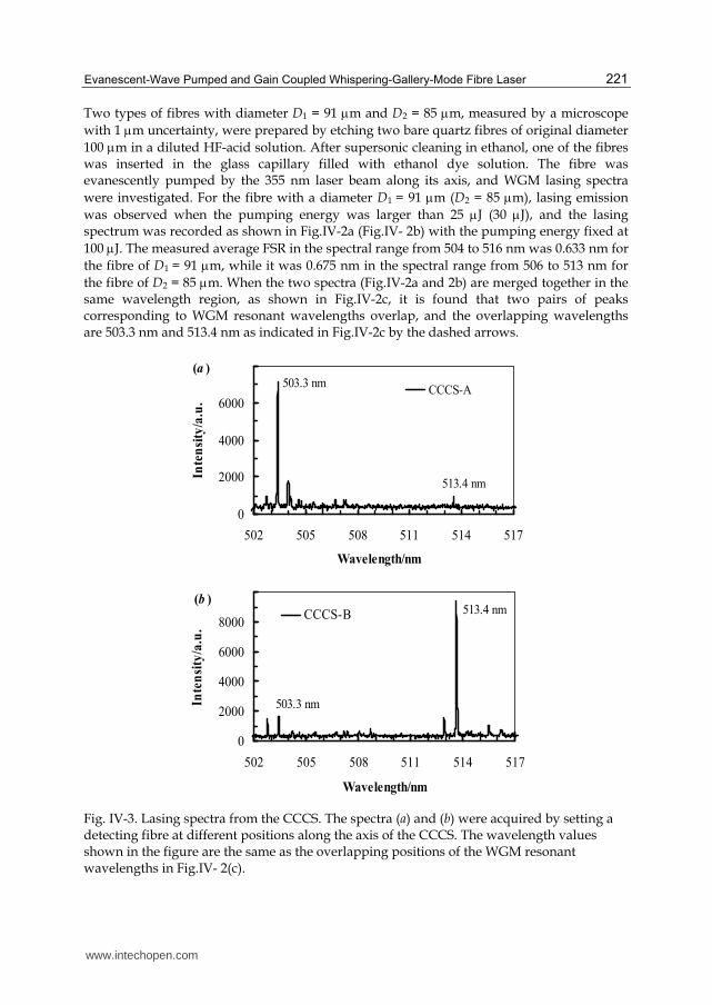
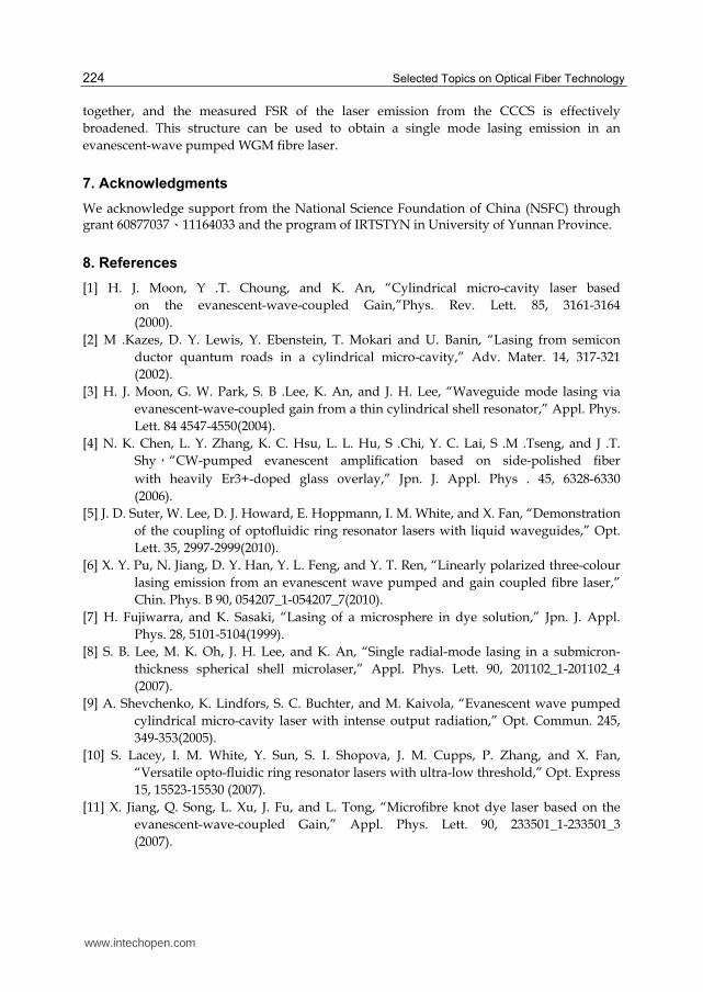
Fig. IV-3. Lasing spectra from the CCCS. The spectra (a) and (b) were acquired by setting a detecting fibre at different positions along the axis of the CCCS. The wavelength values shown in the figure are the same as the overlapping positions of the WGM resonant wavelengths in Fig.IV- 2(c).
www.intechopen.com
Selected Topics on Optical Fiber Technology
222
After the single fibre experiments, the two fibres (we called the fibre of D = 91 m in
diameter as master fibre, and the fibre of D2 = 85 m in diameter as slave fibre) were bound
together with their axes parallel by two fine hairs to form a CCCS. The CCCS was then
inserted in the same glass capillary as shown in Fig.IV-1b, evanescently pumped by the 355
nm laser beam along the axis of the master fibre (pumping energy was fixed at 100 J), the
lasing emissions were observed along the rims of both fibres, and the lasing spectra
recorded were shown in Fig.IV-3. The CCCS suppresses most of WGM resonant peaks
shown in Fig.IV-3. However, a strong lasing peak appears at 503.3 nm and a weak peak
appears at 513.4 nm, where two pairs of peaks overlap together as shown in Fig.IV-2c. When
the detecting fibre was moved to another position along the master fibre’s axis, as shown in
Fig.IV-3b, we obtained another lasing spectrum similar to that shown in Fig.IV-3a from the
CCCS, in which most of WGM resonant peaks have been suppressed, such that a strong
lasing peak appears at 513.4 nm and a weak peak appears at 503.3 nm. The wavelength
difference between the strong and the weak peaks is 10.1 nm. This value, corresponding to
FSR of the CCCS, is 16 and 15 times larger than that of the master and slave fibres,
respectively. That is FSR is broadened by using the CCCS. The lasing peaks around 503.3
and 513.4 nm are possibly caused by the partial overlap of resonant frequencies between the
WGMs of the main and the slave fibres.
5.2 Discussion and conclusion
Let D and m be the diameter and the refractive index of a circular cavity, respectively, the
WGM resonant condition can be approximately written as Dm N , where is resonant
wavelength, N is an integer. For the master and the slave fibres, the resonant conditions are
given by,
1 1 1D m N , (IV-1)
2 2 2D m N (IV-2)
For a CCCS composed by two circular cavities, based on Vernier effect, the resonance occurs
only at the same wavelength of both cavities satisfies resonant condition, which leads to
1 2 1 2( ) ( ) CCCSD D m N N , where CCCS is the resonant wavelength of the CCCS.
Therefore, the FSR of the CCCS can be written as,
2
1 2( )CCCS
CCCS CCCSFSRD D m
. (IV-3)
Instead of using the measured diameters of the two fibres, we utilize the spectral diameter
defined by mDs /2 to calculate
CCCS , where is the measured FSR from the
lasing spectrum shown in Fig.IV- 2. For the master and the slave fibres, the spectral
diameters are 1sD = 89.6 m ( = 0.633 nm) and 2
sD = 84.0 m ( = 0.675 nm),
respectively. Substituting the values of 1sD and 2
sD , together with m = 1.46 into equation (3),
the calculated CCCS is 10.28 nm for CCCS = 513.4 nm, and 9.87 nm for CCCS = 503.3 nm. The
average value of CCCS is 10.08 nm, which is very close to the measured FSR of the CCCS.
www.intechopen.com
Evanescent-Wave Pumped and Gain Coupled Whispering-Gallery-Mode Fibre Laser
223
A broad FSR can also be obtained by using a single fibre of small diameter. For example, the
diameter must be reduced to about 6 m to obtain the same FSR as the CCCS used in this work. However, a fibre of small diameter means a low efficiency to couple the pumping energy into the fibre, as well as a decrease in its quality factor due to a larger leakage loss, especially when the cavity is immersed in a liquid solution.
The difference between the geometric diameters (D1 = 91 m, D2 = 85 m) and the spectral
diameters ( 1sD = 89.6 m, 2
sD = 84.0 m) is mainly caused by the property of intensity
distribution of WGMs. Most of photons in a WGM don’t travel strictly along the inner
surface of a circular cavity, but slightly inside the surface. Therefore, the spectral diameter
( siD ) calculated by the measured FSR of a circular cavity is always smaller than its geometric
diameter ( iD ).
6. Chapter summary
Threshold property of the novel WGM fiber lasers pumped by an evanescent-wave has
been investigated . The laser has been fabricated by inserting a bare fused quartz fiber into
a glass capillary filled with dye solution, and its energy threshold properties, including
the energy threshold varied with the RI of the dye solution for different fiber diameters
and the produced length of lasing emission, are experimentally studied. We find that the
energy threshold is very sensitive to the change of the refractive index of dye solutions
and the fiber diameter, and the produced length of lasing emission is dependent on dye
concentration and the refractive index of dye solutions. Based on the characteristic of
evanescent-wave pumping scheme, we derive the threshold energy formula of the WGM
fiber lasers from the general theory of WGM microcavity laser. Based on the characteristic
of frustrated totally internal reflection of light traveling along the fiber, we obtain the
equation. to determine the produced length of lasing emission according to the
characteristic of FITR of light traveling along the fiber. The calculated results with our
theory fit the experimental data very well.
The polarization property of lasing emission, for the evanescent-wave pumped WGM fibre
laser, is related closely to the light-pump conditions. When pump beams travel strictly along
the axis of the optical fibre, only TE wave exists in lasing emission, and the electric vector of
the lasing emission goes along the radial direction of the fibre, which forms a special radial
polarization emission whose emitting direction is vertical to the fibre’s axis. When pump
beams are deviated from the axis of the optical fibre, both TE and TM waves exist in lasing
emission, which forms a special emission mixed with radial and axial polarization emission,
and the emitting direction is also vertical to the fibre’s axis.
For an evanescent-wave pumped and gain coupled WGM fiber laser, the dye gain is excited
by the evanescent wave of the pumped light, distributed around the fiber and coupled into
WGMs of a circular cavity. A good spatial overlap between the dye gain and the evanescent
fields of WGMs leads to a high pumping efficiency and a longer gain distance along the
fiber, and linearly polarized three-color lasing emissions from a single optical fiber can be
realized by immersing the fiber into three different dye solutions, where may be found a
potential application in multicolor display.
Evanescent-wave pumping scheme has been successfully used to excite WGM fibre laser. A
coupled cylinder-cavity structure has been fabricated by binding two bare optical fibres
www.intechopen.com
Selected Topics on Optical Fiber Technology
224
together, and the measured FSR of the laser emission from the CCCS is effectively
broadened. This structure can be used to obtain a single mode lasing emission in an
evanescent-wave pumped WGM fibre laser.
7. Acknowledgments
We acknowledge support from the National Science Foundation of China (NSFC) through grant 60877037、11164033 and the program of IRTSTYN in University of Yunnan Province.
8. References
[1] H. J. Moon, Y .T. Choung, and K. An, “Cylindrical micro-cavity laser based
on the evanescent-wave-coupled Gain,”Phys. Rev. Lett. 85, 3161-3164
(2000).
[2] M .Kazes, D. Y. Lewis, Y. Ebenstein, T. Mokari and U. Banin, “Lasing from semicon
ductor quantum roads in a cylindrical micro-cavity,” Adv. Mater. 14, 317-321
(2002).
[3] H. J. Moon, G. W. Park, S. B .Lee, K. An, and J. H. Lee, “Waveguide mode lasing via
evanescent-wave-coupled gain from a thin cylindrical shell resonator,” Appl. Phys.
Lett. 84 4547-4550(2004).
[4] N. K. Chen, L. Y. Zhang, K. C. Hsu, L. L. Hu, S .Chi, Y. C. Lai, S .M .Tseng, and J .T.
Shy,“CW-pumped evanescent amplification based on side-polished fiber
with heavily Er3+-doped glass overlay,” Jpn. J. Appl. Phys . 45, 6328-6330
(2006).
[5] J. D. Suter, W. Lee, D. J. Howard, E. Hoppmann, I. M. White, and X. Fan, “Demonstration
of the coupling of optofluidic ring resonator lasers with liquid waveguides,” Opt.
Lett. 35, 2997-2999(2010).
[6] X. Y. Pu, N. Jiang, D. Y. Han, Y. L. Feng, and Y. T. Ren, “Linearly polarized three-colour
lasing emission from an evanescent wave pumped and gain coupled fibre laser,”
Chin. Phys. B 90, 054207_1-054207_7(2010).
[7] H. Fujiwarra, and K. Sasaki, “Lasing of a microsphere in dye solution,” Jpn. J. Appl.
Phys. 28, 5101-5104(1999).
[8] S. B. Lee, M. K. Oh, J. H. Lee, and K. An, “Single radial-mode lasing in a submicron-
thickness spherical shell microlaser,” Appl. Phys. Lett. 90, 201102_1-201102_4
(2007).
[9] A. Shevchenko, K. Lindfors, S. C. Buchter, and M. Kaivola, “Evanescent wave pumped
cylindrical micro-cavity laser with intense output radiation,” Opt. Commun. 245,
349-353(2005).
[10] S. Lacey, I. M. White, Y. Sun, S. I. Shopova, J. M. Cupps, P. Zhang, and X. Fan,
“Versatile opto-fluidic ring resonator lasers with ultra-low threshold,” Opt. Express
15, 15523-15530 (2007).
[11] X. Jiang, Q. Song, L. Xu, J. Fu, and L. Tong, “Microfibre knot dye laser based on the
evanescent-wave-coupled Gain,” Appl. Phys. Lett. 90, 233501_1-233501_3
(2007).
www.intechopen.com
Evanescent-Wave Pumped and Gain Coupled Whispering-Gallery-Mode Fibre Laser
225
[12] C. Monat, P. Domachuk, and B. J. Eggleton, “Integrated optofluidics: A new river of
light,” Nat. Photonics 1, 106-114(2007).
[13] Y. Sun, S. I. Shopovab, C. S. Wu, S. Arnold, and X. Fan, “Bioinspired optofluidic FRET
lasers via DNA scaffolds,” PNAS 37, 16039-16042(2010).
[14] X .Y. Pu, N. Jiang, R. Bai, W. L . Xiang,Y. X. Zhang, and D. Y. Han, “A novel micro-
cavity fiber laser with three-colorWGM lasing emission in a single optical fiber,”
Chinese Patent No.ZL200810058304 (30 Sep. 2009).
[15] K. M. Djafar, and L. S. Lowell, Fibre-optic Communications Technology(Science Press,
Beijing, 106-108(2002)).
[16] M. Born, and E. Wolf, Principles of Optics(Cambridge University Press, Cambridge,
1997).
[17] C. F. Bohren, and D. R. Huffman, Absorption and Scattering of Light by Small Particles(John
Wiley & Sons,New York, 1998).
[18]Y. X. Zhang, X.Y. Pu, K. Zhu, and L. Feng, “Threshold property of Whispering- Gallery-
Mode fiber lasers pumped by evanescent-wave,” J. Opt. Soc. of Am. B. 28, 2048-
2056 (2011)
[19] Y. S. Choi, H. J. Moon, K. Y. An, S. B. Lee, J .H. Lee, and J. S. Chang, “Ultrahigh-Q
Microsphere Dye Laser Based on Evanescent-Wave Coupling,” J. Korean Phys Soc.
39, 928-931(2001).
[20] C. C .Lam, P. Y .Leung, and K. Yang , “Explicit asymptotic formulas for the positions,
widths, and strengths of resonances in Mie scattering,” J. Opt. Soc. of Am. B. 9,
1585-1592(1992).
[21] D. L. Wang, N. Jiang, L. Q. Jiang, and X. Y. Pu, “The precise assignment of whispering
gallery modes for lasing spectra emitting from cylindrical micro-cavities (in
Chinese),” Spectroscopy Spectr Anal.28, 2749-2753(2008).
[22] D. G. Hall, “Vector-beam solutions of Maxwell’s wave quation,” Opt. Lett. 21, 9-11
(1996).
[23] Q. Zhan, J. R. Leger, “Microellipsometer with radial symmetry,” Appl. Opt. 41, 4630-
4637(2002).
[24] P. W. Barber, S. C. Hill, Light scattering by particles: computational methods. (World
Scientific Publishing Co Pte Ltd, Singapore, 25-77(1990)).
[25] J. D. Jackson, Classical Electrodynamics. (Advanced Education Press, Beijing, 306-308
(2001)).
[26] E. S. C. Ching, P. T. Leung, K. Young, The role of Quasi-normal Modes-Optical Processes in
Microcavities, edited by R. K. Chang and A. J. Campillo. (World Scientific
Publishing Co Pte Ltd, Singapore, 1-75(1996)).
[27] X. Y. Pu, R. Bai, W. L. Xiang, F. Du and N. Jiang,“Two-wavelength-range whispering-
gallery-mode fiber laser pumped by evanescent wave,” Acta Phys. Sin. 58, 3923-
3928(2009).
[28] R. Yang, W. H. Yu, Y. Bao, Y. X. Zhang and X. Y. Pu, “whispering-gallery modes based
on evanescent field in cylindrical micro-cavity,” Acta Phys. Sin. 57, 6414-6418
(2008).
www.intechopen.com
Selected Topics on Optical Fiber Technology
226
[29] K. Oda, N. Takato, and H. Toba, “A wide-FSR waveguide double-ring resonator for
optical FDM transmission systems,” IEEEJ. Light wave Technol. 9, 728-736
(1991).
[30] L. Shang, L. Liu, and L. Xu, “Single-frequency coupled asymmetric microcavity
laser,”Opt. Lett. 33, 1150-1152 (2008).
[31] X. Wu, Y. Z. Sun, J. D. Suter, and X. D. Fan, “Single mode coupled optofluidic
ring resonator dye lasers,” Appl. Phys. Lett. 94 241109_1-241109_3
(2009).
www.intechopen.com
Selected Topics on Optical Fiber TechnologyEdited by Dr Moh. Yasin
ISBN 978-953-51-0091-1Hard cover, 668 pagesPublisher InTechPublished online 22, February, 2012Published in print edition February, 2012
InTech EuropeUniversity Campus STeP Ri Slavka Krautzeka 83/A 51000 Rijeka, Croatia Phone: +385 (51) 770 447 Fax: +385 (51) 686 166www.intechopen.com
InTech ChinaUnit 405, Office Block, Hotel Equatorial Shanghai No.65, Yan An Road (West), Shanghai, 200040, China
Phone: +86-21-62489820 Fax: +86-21-62489821
This book presents a comprehensive account of the recent advances and research in optical fiber technology.It covers a broad spectrum of topics in special areas of optical fiber technology. The book highlights thedevelopment of fiber lasers, optical fiber applications in medical, imaging, spectroscopy and measurement,new optical fibers and sensors. This is an essential reference for researchers working in optical fiberresearches and for industrial users who need to be aware of current developments in fiber lasers, sensors andother optical fiber applications.
How to referenceIn order to correctly reference this scholarly work, feel free to copy and paste the following:
Xiao-Yun Pu, Yuan-Xian Zhang and Li Feng (2012). Evanescent-Wave Pumped and Gain CoupledWhispering-Gallery-Mode Fibre Laser, Selected Topics on Optical Fiber Technology, Dr Moh. Yasin (Ed.),ISBN: 978-953-51-0091-1, InTech, Available from: http://www.intechopen.com/books/selected-topics-on-optical-fiber-technology/evanescent-wave-pumped-and-gain-coupled-whispering-gallery-mode-fibre-laser

© 2012 The Author(s). Licensee IntechOpen. This is an open access articledistributed under the terms of the Creative Commons Attribution 3.0License, which permits unrestricted use, distribution, and reproduction inany medium, provided the original work is properly cited.


![Whispering Pines [1948]](https://img.pdfslide.us/doc/110x75/622dd9de07e5ed329f421c2d/whispering-pines-1948.jpg)