Embed Size (px)
Citation preview
EVALUATION OF VARIED FERRULE GEOMETRY ON THE FRACTURE RESISTANCE OF ENDODONTICALLY TREATED MAXILLARY
CENTRAL INCISORS- AN IN VITRO STUDY
Dissertation submitted to
THE TAMILNADU Dr. M.G.R. MEDICAL UNIVERSITY
In partial fulfillment for the Degree of
MASTER OF DENTAL SURGERY
BRANCH I PROSTHODONTICS AND CROWN & BRIDGE
APRIL 2013

CERTIFICATE
This is to certify that this dissertation titled “EVALUATION OF VARIED
FERRULE GEOMETRY ON THE FRACTURE RESISTANCE OF
ENDODONTICALLY TREATED MAXILLARY CENTRAL INCISORS- AN
IN VITRO STUDY” is a bonafide record of work done by Dr. Vinod Narayanan
under my guidance during his postgraduate study period 2010 – 2013.
This dissertation is submitted to THE TAMILNADU Dr. M.G.R.
MEDICAL UNIVERSITY, in partial fulfillment for the award of the degree of
Master of Dental Surgery in Prosthodontics and Crown and Bridge. It has not
been submitted (partial or full) for the award of any other degree or diploma.
Guide:
Date:
Place: Coimbatore
Dr. ANJANA KURIEN, M.D.S.,
Professor,
Department of Prosthodontics Including Crown and bridge and Implantology
Dr. V.R.THIRUMURTHY M.D.S.,
Vice Principal,
Professor and H.O.D,
Department of Prosthodontics Including Crown and bridge and Implantology
Dr. V.PRABHAKAR, M.D.S.,
PRINCIPAL,
Sri Ramakrishna Dental College and Hospital,
Coimbatore-641006
ACKNOWLEDGEMENT
My utmost gratitude to my Prof (Dr).V.R Thirumurthy, Head of the
Department of Prosthodontics for the insights he has shared. His sincerity, quest for
perfection and encouragement has made me what I am today.
I convey my sincere and heartfelt thanks to my Guide Prof (Dr).Anjana
Kurien, Department of Prosthodontics who has always given me valuable support.
I avail this opportunity to sincerely and heartfully thank Dr. K.S.Limson,
Associate professor, Department of Prosthodontics, for his optimistic attitude
towards the profession and life in general.
Dr.Y.A Bindhoo, Reader, Department of Prosthodontics, has been my
inspiration as I hurdle all the obstacles in the completion of this thesis. It would not
have been possible for me to complete this task without her rigorous scientific
approach and the dedicating spirit for work.
I also take this opportunity to express my sincere gratitude to Dr. Sunil
Joseph Jacob, Senior lecturer and Dr. Sathya Shanker, Senior lecturer, Department
of Prosthodontics for being a constant source of encouragement, and support.
I take this opportunity to thank Prof (Dr).V.Prabhakar, Principal for his
support and facilities provided in the college.
I express my sincere thanks to Dr.K.Palanivelu, Professor and Head. Central
institute of plastic and technology, permitting to use the various testing equipment’s
available in the institution to conduct the test. I also pay my thanks to
Dr.P.T.Saleendran, Statistician, for his help in this study.
I would like to thank my colleagues, and department staff for their constant
support and help rendered without any hesitation whenever I needed.
Finally, but definitely not the least, I express my gratitude to my family. I am
so appreciative for their constant love, understanding and encouragement.
Thank you lord for my imperfections and failures are as much a blessing from
you as my successes and my talents and I lay them both at your feet.
CONTENTS
TITLE PAGE No
1. INTRODUCTION
1
2. AIM OF THIS STUDY
5
3. REVIEW OF LITERATURE
6
4. MATERIALS AND METHODS
24
5. RESULTS
42
6. DISCUSSION
57
7. SUMMARY AND CONCLUSION 69
8. BIBLIOGRAPHY
71
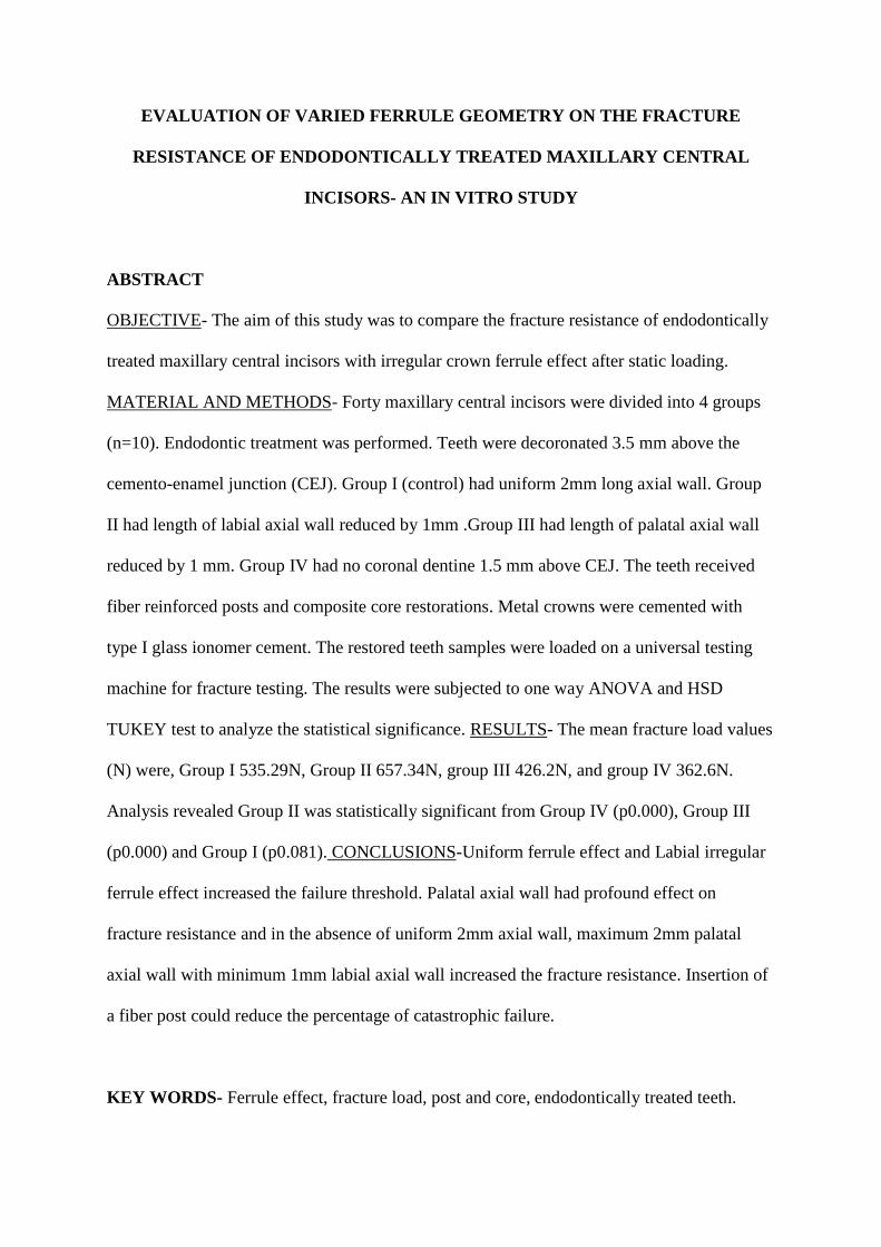
EVALUATION OF VARIED FERRULE GEOMETRY ON THE FRACTURE
RESISTANCE OF ENDODONTICALLY TREATED MAXILLARY CENTRAL
INCISORS- AN IN VITRO STUDY
ABSTRACT
OBJECTIVE- The aim of this study was to compare the fracture resistance of endodontically
treated maxillary central incisors with irregular crown ferrule effect after static loading.
MATERIAL AND METHODS- Forty maxillary central incisors were divided into 4 groups
(n=10). Endodontic treatment was performed. Teeth were decoronated 3.5 mm above the
cemento-enamel junction (CEJ). Group I (control) had uniform 2mm long axial wall. Group
II had length of labial axial wall reduced by 1mm .Group III had length of palatal axial wall
reduced by 1 mm. Group IV had no coronal dentine 1.5 mm above CEJ. The teeth received
fiber reinforced posts and composite core restorations. Metal crowns were cemented with
type I glass ionomer cement. The restored teeth samples were loaded on a universal testing
machine for fracture testing. The results were subjected to one way ANOVA and HSD
TUKEY test to analyze the statistical significance. RESULTS- The mean fracture load values
(N) were, Group I 535.29N, Group II 657.34N, group III 426.2N, and group IV 362.6N.
Analysis revealed Group II was statistically significant from Group IV (p0.000), Group III
(p0.000) and Group I (p0.081). CONCLUSIONS-Uniform ferrule effect and Labial irregular
ferrule effect increased the failure threshold. Palatal axial wall had profound effect on
fracture resistance and in the absence of uniform 2mm axial wall, maximum 2mm palatal
axial wall with minimum 1mm labial axial wall increased the fracture resistance. Insertion of
a fiber post could reduce the percentage of catastrophic failure.
KEY WORDS- Ferrule effect, fracture load, post and core, endodontically treated teeth.

INTRODUCTION

Introduction 1
INTRODUCTION
Is it better to have second chance to correct the fallacies of the first, it always is… and
what if there is no second chance? These scenarios are especially relevant when restoring
endodontically treated maxillary central incisor.
Clinicians are confronted with difficult choices regarding whether a nonvital tooth should
be saved through endodontic treatment or be extracted and replaced with an implant96. The
concept of evidence-based dentistry essentially states that treatment plans should be devised
based on the best available evidence from the literature using the experience and wisdom of the
practitioner and the needs and desires of the patient73. Major studies published to date indicate
that there is no difference in long-term prognosis between single-tooth implants and restored root
canal treated teeth42. Therefore, the decision to treat a tooth endodontically or to place a single
tooth implant should be based on other criteria such as prosthetic restorability of the tooth,
quality of bone, aesthetic demands, cost-benefit ratio, systematic factors, potential for adverse
effects, and patient preferences. It can be concluded that endodontic treatment of teeth represents
a feasible, practical, and economical way to preserve function in a vast array of cases and that
dental implants serve as a good alternative in selected indications in which prognosis is poor42.
Prosthetic restoration of endodontically treated tooth requires post and core foundation to
achieve sufficient anchorage when more than 50% of coronal structure is missing. Currently
posts are not believed to function as a reinforcing component of prosthetic treatment but rather as
an element supporting and anchoring a core foundation, when there is an insufficient clinical
crown10, 18, 19, 63, 86, 87, 101.
Introduction 2
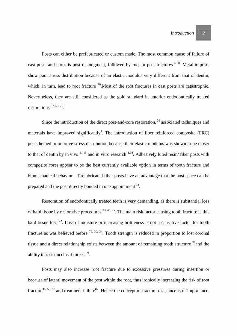
Posts can either be prefabricated or custom made. The most common cause of failure of
cast posts and cores is post dislodgment, followed by root or post fractures 63,86.Metallic posts
show poor stress distribution because of an elastic modulus very different from that of dentin,
which, in turn, lead to root fracture 76.Most of the root fractures in cast posts are catastrophic.
Nevertheless, they are still considered as the gold standard in anterior endodontically treated
restorations 37, 53, 76.
Since the introduction of the direct post-and-core restoration, 58 associated techniques and
materials have improved significantly1. The introduction of fiber reinforced composite (FRC)
posts helped to improve stress distribution because their elastic modulus was shown to be closer
to that of dentin by in vivo 21,15 and in vitro research 1,58. Adhesively luted resin/ fiber posts with
composite cores appear to be the best currently available option in terms of tooth fracture and
biomechanical behavior5. Prefabricated fiber posts have an advantage that the post space can be
prepared and the post directly bonded in one appointment 63.
Restoration of endodontically treated teeth is very demanding, as there is substantial loss
of hard tissue by restorative procedures 33, 46, 95. The main risk factor causing tooth fracture is this
hard tissue loss 72. Loss of moisture or increasing brittleness is not a causative factor for tooth
fracture as was believed before 79, 30, 34. Tooth strength is reduced in proportion to lost coronal
tissue and a direct relationship exists between the amount of remaining tooth structure 97and the
ability to resist occlusal forces 69.
Posts may also increase root fracture due to excessive pressures during insertion or
because of lateral movement of the post within the root, thus ironically increasing the risk of root
fracture36, 53, 98 and treatment failure87. Hence the concept of fracture resistance is of importance.
Introduction 3
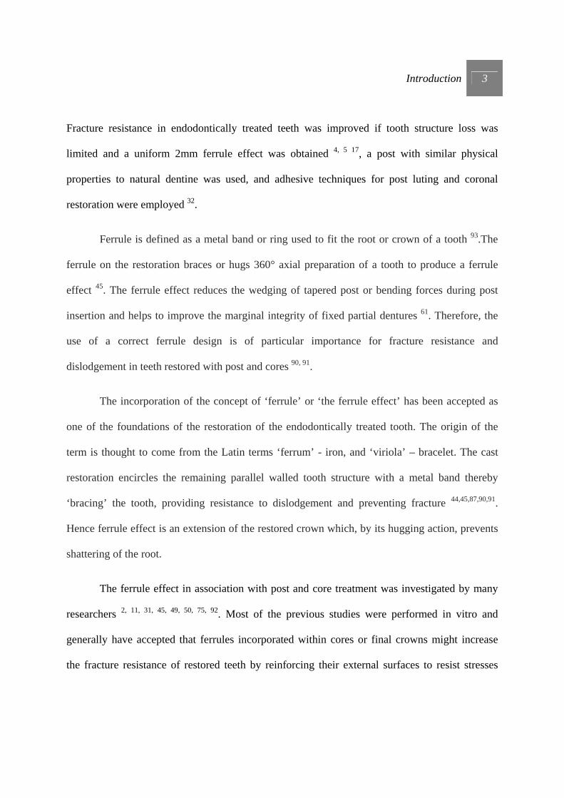
Fracture resistance in endodontically treated teeth was improved if tooth structure loss was
limited and a uniform 2mm ferrule effect was obtained 4, 5 17, a post with similar physical
properties to natural dentine was used, and adhesive techniques for post luting and coronal
restoration were employed 32.
Ferrule is defined as a metal band or ring used to fit the root or crown of a tooth 93.The
ferrule on the restoration braces or hugs 360° axial preparation of a tooth to produce a ferrule
effect 45. The ferrule effect reduces the wedging of tapered post or bending forces during post
insertion and helps to improve the marginal integrity of fixed partial dentures 61. Therefore, the
use of a correct ferrule design is of particular importance for fracture resistance and
dislodgement in teeth restored with post and cores 90, 91.
The incorporation of the concept of ‘ferrule’ or ‘the ferrule effect’ has been accepted as
one of the foundations of the restoration of the endodontically treated tooth. The origin of the
term is thought to come from the Latin terms ‘ferrum’ - iron, and ‘viriola’ – bracelet. The cast
restoration encircles the remaining parallel walled tooth structure with a metal band thereby
‘bracing’ the tooth, providing resistance to dislodgement and preventing fracture 44,45,87,90,91.
Hence ferrule effect is an extension of the restored crown which, by its hugging action, prevents
shattering of the root.
The ferrule effect in association with post and core treatment was investigated by many
researchers 2, 11, 31, 45, 49, 50, 75, 92. Most of the previous studies were performed in vitro and
generally have accepted that ferrules incorporated within cores or final crowns might increase
the fracture resistance of restored teeth by reinforcing their external surfaces to resist stresses

Introduction 4
accompanied by functional lever forces. Ferrules also help to maintain the integrity of cement
seal around the restoration 91.
Under clinical conditions, maxillary incisors are often centrally or laterally
damaged 95, 105. Occlusal overload causes a fracture from palatal to facial, often at a sub-gingival
level on the facial side of the tooth. Proximal cavities leave hard tooth tissue only on the facial
and palatal side 61. Traumatic injury results in coronal fracture on the facial side, which extends
in cervical-palatal direction. In such cases, a favorable 2-mm ferrule effect is difficult to achieve.
Hence the various questions that arise are…
Which direct and indirect factors influences ferrule functionality?
As to what extent the degree of dentin preservation influences the success of the ferruled,
endodontically treated anterior restoration?
AIM OF THIS STUDY
Aim of this study 5
AIM OF THIS STUDY
1} To evaluate and compare fracture resistance of endodontically treated teeth, with and without
ferrule effect.
2} To evaluate and compare fracture resistance of endodontically treated teeth having uniform
2mm ferrule effect with non-uniform ferrule effect.
3} To evaluate and compare fracture resistance of endodontically treated teeth having
nonuniform palatal and nonuniform labial ferrule effect.
The tested null hypothesis was that the amount and location of residual coronal dentin (axial wall
for ferrule effect) does not significantly affect fracture resistance of endodontically treated teeth.
REVIEW OF LITERATURE

Review of literature 6
REVIEW OF LITERATURE
A ferrule or encircling band of cast metal around the coronal surface of the tooth has been
suggested to improve the integrity of the endodontically treated tooth. The ferrule as part of core
or the crown is purported to prevent tooth fracture. The purpose of the ferrule is to improve the
structural integrity of the pulpless tooth by counteracting the functional lever forces, avoiding the
wedging effect of tapered dowels and the lateral forces exerted during insertion of the dowel.
Several authors have suggested that the crown should extend 2 mm beyond the tooth-core
junction to ensure a protective ferrule effect 88.
Rosen 75 (1961) in a review of literature focused on establishing norms for the correct
reconstruction and build-up of root canal treated teeth. He stated that operative
procedures following endodontic therapy are as important as the root canal treatment
itself. He recommended that such teeth must be reinforced or supported with either an
intracoronal “crutch” or an extra coronal “brace,” or both. The intracoronal crutch is a
cast post or dowel which extends into a preparation made in the root canal and is
continuous with a core. The extra coronal brace is a subgingival collar or apron of gold
which extends as far as possible beyond the gingival seat of the core and completely
surrounds the perimeter of the cervical part of the tooth. It is an extension of the restored
crown which, by its hugging action, prevents vertical shattering of the root. He further
stated that by virtue of its exaggerated gingival extension, this apron of gold contributes
to mechanical retention- for the restoration as well as prevention of recurrence of decay
in mouths which have little or no immunity against caries.
Review of literature 7
In 1978, Trabert, Caput and Abou-Rass 98 conducted a study to analyze the strength of
teeth treated with stainless steel post. Posts with different diameter, width, and lengths
where used. They verified that the post with smaller diameters preserve greater amount
of tooth structure thereby significantly increasing the resistance to fracture.
Hoag and Dwyer 38 (1982) in their vitro study evaluated post and core techniques with
and without full crown coverage on extracted mandibular molar teeth. They concluded
that the method of post and core technique may not be as significant as the placement of
full coverage cast-gold crown restorations and placement of margins beyond the buildup
restoration.
Sorensen and Martinoff 86 (1984) evaluated 1273 endodontically treated teeth for clinical
significance by post reinforcement and coronal coverage. After comparing the success
and failure of the groups, it appeared that some teeth were more prone to failure
regardless of restorative technique. Maxillary anterior teeth are more susceptible to
trauma than premolars or molars because of arch position. The difference in direction of
forces during function in maxillary anterior teeth vs. mandibular anterior teeth may also
account for the discrepancy in the failure rate between the two. Mandibular anterior teeth
are subject to more vertical forces closer to their long axis, while maxillary anterior teeth
receive more angular forces. Significant loss of tooth structure while obtaining canal
access during endodontic therapy may sufficiently weaken the maxillary anterior teeth
despite the restoration that is placed. They concluded that the records of 1273
endodontically treated teeth suggest: 1. there was no significant increase in resistance to
fracture or dislodgment gained with intracoronal reinforcement for the six anatomic

Review of literature 8
groups of teeth. 2. Coronal coverage did not significantly improve the rate of clinical
success for maxillary and mandibular anterior teeth. 3. The rate of clinical success was
significantly improved with coronal coverage of maxillary and mandibular premolars and
molars.
Tjan and Whang 94 (1985) investigated 1) resistance to fracture under horizontal force
and the failure characteristics of dowel channels on maxillary central incisors with
various thicknesses of remaining buccal dentin and (2) studied the effect of a metal collar
on the resistance of roots to fracture. They concluded that dowel channels with 1 mm of
remaining buccal dentin walls were apparently more prone to fracture under horizontal
impact than those that had 2 or 3 mm of buccal dentin walls.
Assif et al 8 (1989) examined the compressive forces exerted by endodontic posts, using
photo elastic models. On the basis of this model, the following observations were made.
1. Intact teeth induce a wedging effect on the supporting structure under vertical loads.
Under oblique loads, stresses were equally concentrated.2. The placement of a complete
crown changes the pattern of the distribution of externally applied loading to the tooth.
Stresses concentrated around the crown margins.3. Vertical loads applied directly to the
post and core caused high apical stress concentration with the cylindrical post, while the
tapered post design showed equal stress concentration at the cemento enamel junction
(CEJ) and the apex. On oblique loading, CEJ stress concentration intensified for both
post designs. The tapered post in each loading produced less apical stress than the
cylindrical post.4. When a post and core was covered by a complete crown with 2 mm
margins on sound tooth structure and subjected to loading, there was no difference

Review of literature 9
between the two post designs. The placement of the crown intensified the CEJ stress
concentration. It is possible that the complete crown and 2mm margins on sound tooth
structure may be the great equalizer, because it tends to change the distribution of forces
to the root, post, and core complex, with the post characteristics becoming insignificant.
Barkhordar, Radke and Abbasi 11 in the year 1989 examined the effect of a metal collar
with approximate 3 degrees of taper on the resistance of endodontically treated roots to
fracture. Teeth without copings failed at a load of 49.6 kg whereas teeth with metal
collars failed at a load of 65.29 kg. They concluded that reinforcement with a metal collar
is necessary to enhance resistance to root fracture.
Loney, Kotowiez and McDowel 50 (1990) assessed the effect of a metal collar on stress
distribution with cast post and cores. This was studied by using three-dimensional photo
elastic models of maxillary canine teeth of average dimensions. Standardized parallel
post and cores were cemented into the models, with half of the samples incorporating a
1.6 mm metal collar. They suggested that the ferrule may help to unite different portion
of tooth and had significant effect on stress distribution.
Sorensen and Engelman 88 (1990) researched to determine the effect of different post
designs and varying amounts of post-to-canal adaptation on the fracture resistance of
endodontically treated teeth. They concluded that maximum adaptation of the residual
root structure with a tapered post significantly increases the fracture resistance of
endodontically treated teeth, but upon failure render the tooth nonrestorable. Tapered
posts resulted in fractures that were directed more apically and lingually. Parallel-sided

Review of literature 10
posts had a lower frequency of fracture upon failure, involving less tooth structure.
Parallel-sided posts surrounded by large amounts of cement had no significant effect on
failure loads.
Sorensen and Engelman 89 (1990) conducted in vitro study to examine the effect of
various ferrule designs on fracture resistance of endodontically treated anterior teeth.
They concluded that one millimeter of coronal tooth structure above the crown margin
substantially increased the fracture resistance of endodontically treated teeth, whereas a
contra bevel at either the tooth-core junction or the crown margin was ineffective. The
thickness of axial tooth structure at the crown margin did not appreciably improve
resistance to fracture.
The effect of post design on the fracture resistance of endodontically treated premolars
restored with cast crowns was examined in vitro by Assif et al 9 (1993). They concluded
that post design did not influence the fracture resistance of endodontically treated teeth.
They stated that in such teeth, greater importance must be given to crown having a 2 mm
margin on healthy tooth structure.
Libmen and Nicholls 48 (1995) studied varying ferrule heights from 0.5 to 2.0 mm in 0.5-
mm increments. The results of this study showed that the 0.5 mm and 1.0 mm ferrule
lengths failed at a significantly lower number of cycles than the 1.5 mm and 2.0 mm
ferrule lengths and control teeth. They concluded that to achieve full benefits of ferrule
effect, axial wall be minimum of 1.5 mm in height and have parallel dentinal walls;
crown must totally encircle the tooth, and end on sound tooth structure.
Review of literature 11
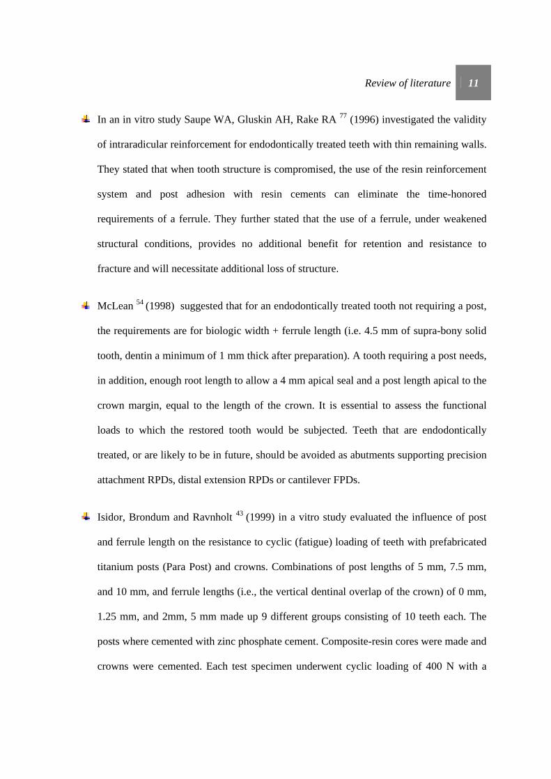
In an in vitro study Saupe WA, Gluskin AH, Rake RA 77 (1996) investigated the validity
of intraradicular reinforcement for endodontically treated teeth with thin remaining walls.
They stated that when tooth structure is compromised, the use of the resin reinforcement
system and post adhesion with resin cements can eliminate the time-honored
requirements of a ferrule. They further stated that the use of a ferrule, under weakened
structural conditions, provides no additional benefit for retention and resistance to
fracture and will necessitate additional loss of structure.
McLean 54 (1998) suggested that for an endodontically treated tooth not requiring a post,
the requirements are for biologic width + ferrule length (i.e. 4.5 mm of supra-bony solid
tooth, dentin a minimum of 1 mm thick after preparation). A tooth requiring a post needs,
in addition, enough root length to allow a 4 mm apical seal and a post length apical to the
crown margin, equal to the length of the crown. It is essential to assess the functional
loads to which the restored tooth would be subjected. Teeth that are endodontically
treated, or are likely to be in future, should be avoided as abutments supporting precision
attachment RPDs, distal extension RPDs or cantilever FPDs.
Isidor, Brondum and Ravnholt 43 (1999) in a vitro study evaluated the influence of post
and ferrule length on the resistance to cyclic (fatigue) loading of teeth with prefabricated
titanium posts (Para Post) and crowns. Combinations of post lengths of 5 mm, 7.5 mm,
and 10 mm, and ferrule lengths (i.e., the vertical dentinal overlap of the crown) of 0 mm,
1.25 mm, and 2mm, 5 mm made up 9 different groups consisting of 10 teeth each. The
posts where cemented with zinc phosphate cement. Composite-resin cores were made and
crowns were cemented. Each test specimen underwent cyclic loading of 400 N with a

Review of literature 12
frequency of 1 load per second at an angulation of 45 degrees to the long axis of the
tooth. They concluded that the ferrule length was more important than post length in
increasing fracture resistance to cyclic loading of crowned teeth.
Gegauff 30 (2000) stated that restoration of mandibular second premolars with completely
missing clinical crowns in the Kennedy Class I and II arches is costly and the risk of
failure is high. A vitro study was done to determine the combined effect of crown
lengthening and placement of a ferrule on the failure resistance to static load of
decoronated and restored mandibular second premolar analog teeth. The combination of
simulated surgical crown-lengthening and more apical crown margin placement to
provide a 2-mm crown ferrule on a decoronated mandibular second premolar analog
resulted in a reduction of static load failure for the restored analog tooth.
In an in vitro study by Al-Hazaimeh N, Gutteridge DL 3 (2001) investigated the effect of
a ferrule preparation on the fracture resistance of crowned central incisors incorporating a
prefabricated post (Parapost) cemented with Panavia-Ex and with a composite core. The
specimens were mounted on a universal testing machine and a compressive load was
applied at an angle of 135 degrees to the palatal surface of the crown until failure
occurred. They concluded that when composite cement and core materials are utilized
with a Para post prefabricated system the additional use of a ferrule preparation has no
benefit in terms of resistance to fracture.
Butz et al 14 in 2001studied the survival rate and fracture strength of endodontically
treated maxillary incisors with moderate coronal defects restored with different post and

Review of literature 13
core systems after exposure to an artificial mouth. They concluded that in the presence of
2mm ferrule effect, prefabricated titanium posts with composite cores, zirconia posts with
heat-pressed ceramic cores, and cast posts and cores yield comparable survival rates for
fracture strengths in the restoration of crowned maxillary incisors. Survival rates and
fracture strengths for zirconia posts with composite cores are significantly lower, so this
combination cannot be recommended for clinical use.
Al-Wahadni A, Gutteridge DL 6 (2002) conducted in vitro study to examine the fracture
resistance of teeth restored with cast post and partial cores supported by different heights
of coronal tooth structure. They concluded that, 3 mm of retained coronal buccal dentine
improved fracture resistance of teeth restored with partial post and cores when compared
to teeth without retained coronal dentine.
In 2002 Pierrisnard et al 70 analyzed through a study of finite element, the effect of
different corono-radicular reconstruction methods on stress transmission to dental tissues.
Seven 3-dimensional models were created, each representing a tooth embedded in a bony
medium. Within the limitations of this study, it was confirmed that all simulated
reconstructed teeth were more subject to stress in the cervical region. The absence of a
cervical ferrule was found to be a determining negative factor, giving rise to considerably
higher stress levels.
Zhi-Yue and Yu-Xing 106 (2003) assessed in vitro the effects of post-core design and
ferrule on the fracture resistance of root canal treated human maxillary central incisors
restored with metal ceramic crowns. Within the limitations of this study they concluded
Review of literature 14
that not all of the post-core structures tested improved the strength of the endodontically
treated teeth. Those prepared with a 2-mm dentin ferrule more effectively enhanced the
fracture strength of custom cast post-core restored endodontically treated maxillary
central incisors.
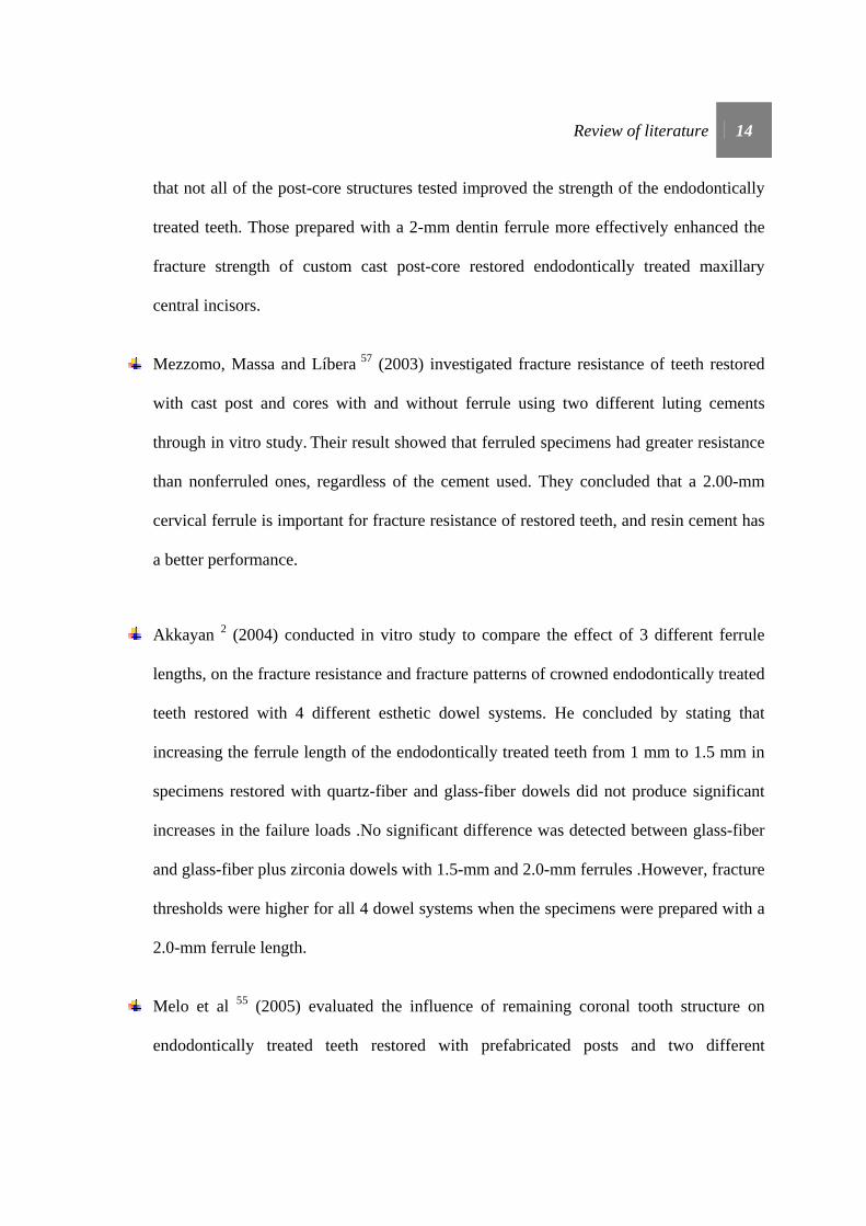
Mezzomo, Massa and Líbera 57 (2003) investigated fracture resistance of teeth restored
with cast post and cores with and without ferrule using two different luting cements
through in vitro study. Their result showed that ferruled specimens had greater resistance
than nonferruled ones, regardless of the cement used. They concluded that a 2.00-mm
cervical ferrule is important for fracture resistance of restored teeth, and resin cement has
a better performance.
Akkayan 2 (2004) conducted in vitro study to compare the effect of 3 different ferrule
lengths, on the fracture resistance and fracture patterns of crowned endodontically treated
teeth restored with 4 different esthetic dowel systems. He concluded by stating that
increasing the ferrule length of the endodontically treated teeth from 1 mm to 1.5 mm in
specimens restored with quartz-fiber and glass-fiber dowels did not produce significant
increases in the failure loads .No significant difference was detected between glass-fiber
and glass-fiber plus zirconia dowels with 1.5-mm and 2.0-mm ferrules .However, fracture
thresholds were higher for all 4 dowel systems when the specimens were prepared with a
2.0-mm ferrule length.
Melo et al 55 (2005) evaluated the influence of remaining coronal tooth structure on
endodontically treated teeth restored with prefabricated posts and two different
Review of literature 15
composites for core build-up. They concluded that remaining coronal tooth structure did
not influence the resistance of endodontically treated teeth; however, the change of core
build-up was able to modify this resistance. They stated that light cured resin core build
up was better than dual cure resin core.
Creugers et al 20, 21 (2005) conducted a prospective clinical study to explore whether
direct composite built up restorations with or without a post and not protected by a
covering cast crown can show acceptable durability over a 5-year observation period.
None of the post free restorations failed. Two restorations with post failed after almost 5
years. Survival difference was not statistically significant.
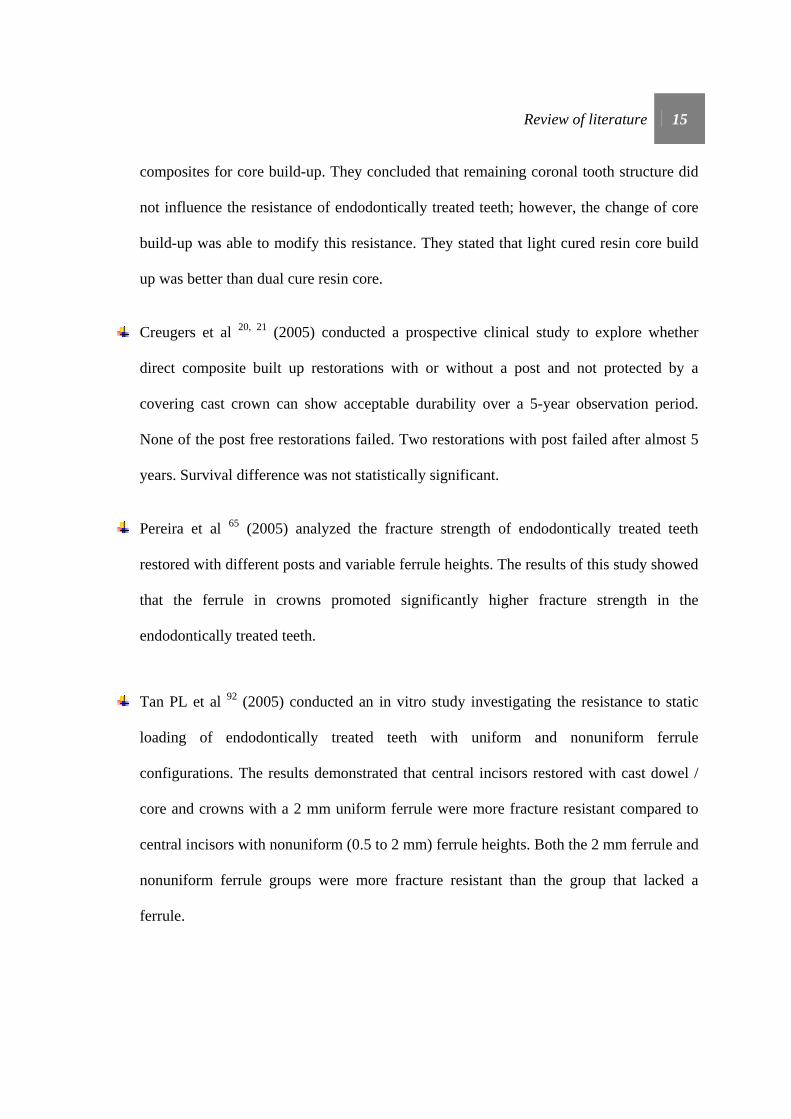
Pereira et al 65 (2005) analyzed the fracture strength of endodontically treated teeth
restored with different posts and variable ferrule heights. The results of this study showed
that the ferrule in crowns promoted significantly higher fracture strength in the
endodontically treated teeth.
Tan PL et al 92 (2005) conducted an in vitro study investigating the resistance to static
loading of endodontically treated teeth with uniform and nonuniform ferrule
configurations. The results demonstrated that central incisors restored with cast dowel /
core and crowns with a 2 mm uniform ferrule were more fracture resistant compared to
central incisors with nonuniform (0.5 to 2 mm) ferrule heights. Both the 2 mm ferrule and
nonuniform ferrule groups were more fracture resistant than the group that lacked a
ferrule.
Review of literature 16
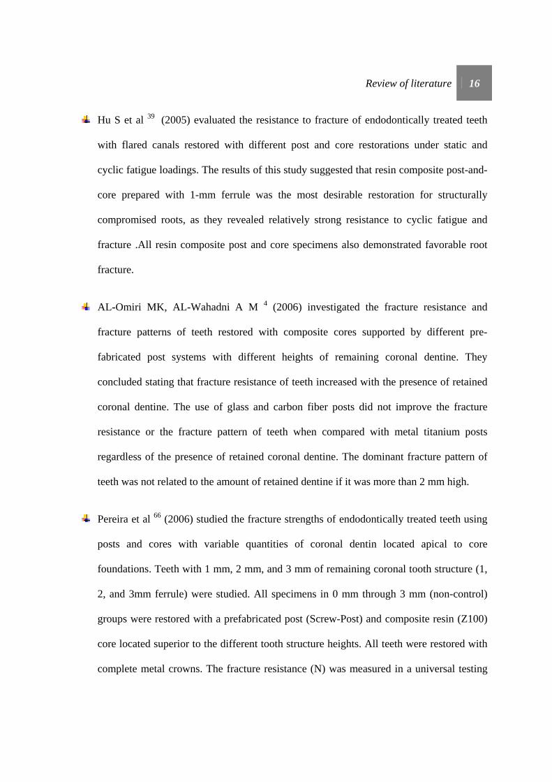
Hu S et al 39 (2005) evaluated the resistance to fracture of endodontically treated teeth
with flared canals restored with different post and core restorations under static and
cyclic fatigue loadings. The results of this study suggested that resin composite post-and-
core prepared with 1-mm ferrule was the most desirable restoration for structurally
compromised roots, as they revealed relatively strong resistance to cyclic fatigue and
fracture .All resin composite post and core specimens also demonstrated favorable root
fracture.
AL-Omiri MK, AL-Wahadni A M 4 (2006) investigated the fracture resistance and
fracture patterns of teeth restored with composite cores supported by different pre-
fabricated post systems with different heights of remaining coronal dentine. They
concluded stating that fracture resistance of teeth increased with the presence of retained
coronal dentine. The use of glass and carbon fiber posts did not improve the fracture
resistance or the fracture pattern of teeth when compared with metal titanium posts
regardless of the presence of retained coronal dentine. The dominant fracture pattern of
teeth was not related to the amount of retained dentine if it was more than 2 mm high.
Pereira et al 66 (2006) studied the fracture strengths of endodontically treated teeth using
posts and cores with variable quantities of coronal dentin located apical to core
foundations. Teeth with 1 mm, 2 mm, and 3 mm of remaining coronal tooth structure (1,
2, and 3mm ferrule) were studied. All specimens in 0 mm through 3 mm (non-control)
groups were restored with a prefabricated post (Screw-Post) and composite resin (Z100)
core located superior to the different tooth structure heights. All teeth were restored with
complete metal crowns. The fracture resistance (N) was measured in a universal testing
Review of literature 17
machine at 45 degrees to the long axis of the tooth until failure. The results of this study
showed that an increased amount of coronal dentin significantly increases the fracture
resistance of endodontically treated teeth.
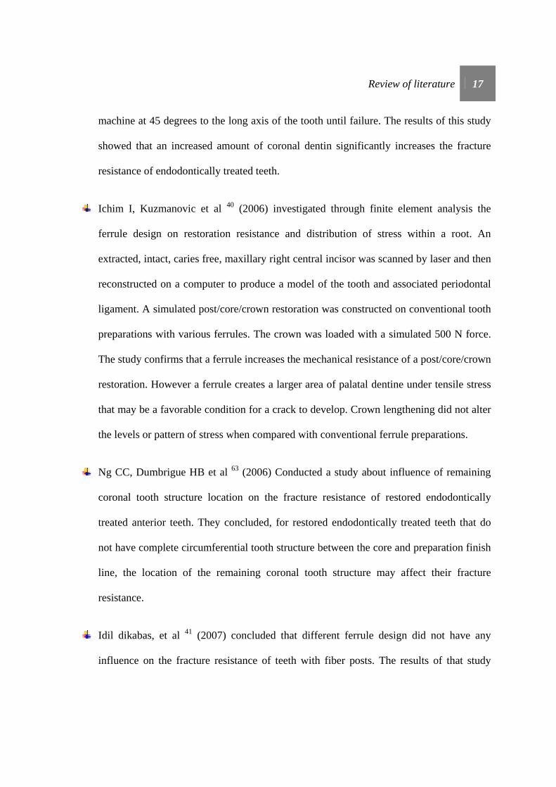
Ichim I, Kuzmanovic et al 40 (2006) investigated through finite element analysis the
ferrule design on restoration resistance and distribution of stress within a root. An
extracted, intact, caries free, maxillary right central incisor was scanned by laser and then
reconstructed on a computer to produce a model of the tooth and associated periodontal
ligament. A simulated post/core/crown restoration was constructed on conventional tooth
preparations with various ferrules. The crown was loaded with a simulated 500 N force.
The study confirms that a ferrule increases the mechanical resistance of a post/core/crown
restoration. However a ferrule creates a larger area of palatal dentine under tensile stress
that may be a favorable condition for a crack to develop. Crown lengthening did not alter
the levels or pattern of stress when compared with conventional ferrule preparations.
Ng CC, Dumbrigue HB et al 63 (2006) Conducted a study about influence of remaining
coronal tooth structure location on the fracture resistance of restored endodontically
treated anterior teeth. They concluded, for restored endodontically treated teeth that do
not have complete circumferential tooth structure between the core and preparation finish
line, the location of the remaining coronal tooth structure may affect their fracture
resistance.
Idil dikabas, et al 41 (2007) concluded that different ferrule design did not have any
influence on the fracture resistance of teeth with fiber posts. The results of that study

Review of literature 18
indicate fiber posts can safely be used for their reinforcing properties. Furthermore, there
is no significant change in the resistance of teeth with fiber posts regardless of which
ferrule design is incorporated. The property of these types of posts is an additional
advantage in clinical practice
Ferrari M, Cagidiaco M.C, et al 29 (2007) conducted a study on survival of endodontically
treated premolars. Over a two-year observation period, post placement resulted in a
significant reduction of failure risk for endodontically treated premolars. With regard to
the influence of residual coronal dentin, failure risk was significantly higher for teeth that
had lost all coronal walls.
Didier Dietschi et al 25 (2007) in a systematic review of literature stated that the best
current approach for restoring endodontically treated teeth seems to (1) minimize tissue
sacrifice, especially in the cervical area so that a ferrule effect can be created, (2) use
adhesive procedures at both radicular and coronal levels to strengthen remaining tooth
structure and optimize restoration stability and retention, and (3) use post and core
materials with physical properties close to those of natural dentin.
Meng QF, Chen YA et al 55 (2007) in a study investigated the effect of a crown
lengthening ferrule on the fracture resistance of endodontically-treated teeth restored with
two dowel-core systems. They concluded that crown lengthening with a 2.0 mm apical
extended ferrule preparation may result in reduced root fracture strengths for
endodontically-treated teeth. A carbon fiber-reinforced dowel-resin core system may
reduce the severity of the root fractures.

Review of literature 19
Hinckfuss et al 37 (2008) evaluated the fracture resistance of bovine teeth restored with
one-piece cast core/crowns and no ferrule, compared to teeth restored with amalgam
cores and full coverage crowns, with and without a dentine ferrule. They concluded that
the maximum load resistance was significantly enhanced by a 2-mm ferrule compared
with teeth with no ferrule and teeth restored with one-piece cast core/crowns. Teeth
restored with one-piece cast core/crowns were significantly more resistant to loading than
teeth restored with amalgam cores and crowns without a ferrule.
Nissan J et al 64 in 2008 examined the influence of a reduced post length sealed with a
titanium-reinforced composite luting agent on the fracture resistance of crowned
endodontically treated teeth with a 2-mm ferrule on healthy tooth structure. Posts were
luted with a titanium-reinforced composite resin luting agent. Titanium-reinforced
composite resin cores were constructed, and cast crowns with a 2- mm ferrule on healthy
tooth structure were cemented. They concluded that within the limitations of this study,
post length did not influence the fracture resistance of crowned endodontically treated
teeth with a 2-mm ferrule on healthy tooth structure. For tooth resistance, prosthesis
design is more important than post characteristics.
Senthil Nathan D, Nayar S 80 (2008) stated, teeth restored with custom cast post core
were better resistant to fracture than teeth restored with prefabricated titanium post
composite core. Ferrule is more important in custom cast post core than in prefabricated
post and composite core.
Review of literature 20
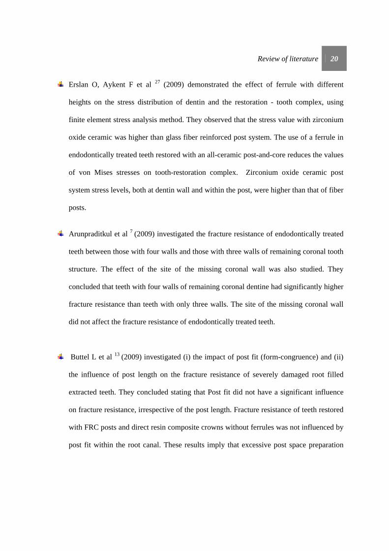
Erslan O, Aykent F et al 27 (2009) demonstrated the effect of ferrule with different
heights on the stress distribution of dentin and the restoration - tooth complex, using
finite element stress analysis method. They observed that the stress value with zirconium
oxide ceramic was higher than glass fiber reinforced post system. The use of a ferrule in
endodontically treated teeth restored with an all-ceramic post-and-core reduces the values
of von Mises stresses on tooth-restoration complex. Zirconium oxide ceramic post
system stress levels, both at dentin wall and within the post, were higher than that of fiber
posts.
Arunpraditkul et al 7 (2009) investigated the fracture resistance of endodontically treated
teeth between those with four walls and those with three walls of remaining coronal tooth
structure. The effect of the site of the missing coronal wall was also studied. They
concluded that teeth with four walls of remaining coronal dentine had significantly higher
fracture resistance than teeth with only three walls. The site of the missing coronal wall
did not affect the fracture resistance of endodontically treated teeth.
Buttel L et al 13 (2009) investigated (i) the impact of post fit (form-congruence) and (ii)
the influence of post length on the fracture resistance of severely damaged root filled
extracted teeth. They concluded stating that Post fit did not have a significant influence
on fracture resistance, irrespective of the post length. Fracture resistance of teeth restored
with FRC posts and direct resin composite crowns without ferrules was not influenced by
post fit within the root canal. These results imply that excessive post space preparation

Review of literature 21
aimed at producing an optimal circumferential post fit is not required to improve fracture
resistance of roots.
Ma PS et al 51 (2009) studied different ferrule lengths with the number of fatigue cycles
needed for failure of the crown cement for an all-ceramic crown cemented with resin
cement. Specimens with a 0.0 mm ferrule survived few fatigue cycles despite the fact that
both the post and crown were bonded with resin cement. Teeth with a 0.5mm ferrule
showed a significant increase in the number of fatigue cycles over the 0.0mm group,
whereas teeth with the 1.0mm ferrule exhibited a significantly higher fatigue cycle count
over the 0.0mm but not the 0.5mm group. They suggested that the clinical implication
were that the 1.5mm ferrule has been suggested for a metal crown with a cast gold post
and core luted with zinc phosphate cement. However, due to the large standard deviation
in the 0.5mm ferrule test group, a minimum 1.0mm ferrule length is recommended when
using core bonding and bonding of an all-ceramic crown for restoration of the structurally
compromised tooth.
Erslan O et al 27 (2009) studied the effect of ferrule with different heights on the stress
distribution of dentin and the restoration-tooth complex, using finite element stress
analysis method. Three-dimensional finite element models simulating an endodontically
treated maxillary central incisor restored with an all-ceramic crown were prepared.
Three-dimensional models were varied in their ferrule height (NF: no ferrule, 1F: 1-mm
ferrule, and 2F:2-mm ferrule). A 300-N static occlusal load was applied to the palatal
surface of the crown with a 135° angle to the long axis of the tooth. The stress values

Review of literature 22
observed with the use of a 2-mm ferrule were lower than the no-ferrule design for both
the glass fiber reinforced and zirconium oxide ceramic post systems, respectively.
Schmitter M et al 78 (2010) conducted a study combining the advantages of in vitro tests
and finite element analysis (FEA) to clarify the effects of ferrule height, post length and
cementation technique used in restoration. All conventionally cemented crowns with a 1-
mm ferrule height failed during artificial ageing, in contrast to resin-bonded crowns (75%
survival rate). FEA confirmed these results and provided information about stress and
force distribution within the restoration. Based on the findings of in vitro tests and
computations they concluded that crowns, especially those with a small ferrule height,
should be resin bonded and failure loads were higher for resin-bonded crowns than for
conventionally cemented crowns.
da Silva NR et al 21 (2010) conducted a study to evaluate the effect of post, core, crown
type, and ferrule presence on the deformation, fracture resistance, and fracture mode of
endodontically treated bovine incisors. Result showed that the ferrule presence did not
significantly influence the buccal strain and fracture resistance for the ceramic crown
groups, irrespective of core and crown type. Ferrule presence resulted in lower strains
and higher fracture resistance in the metal crown groups, irrespective of core. The cast
post and core showed lower strain values than groups with glass fiber posts when restored
with metal crowns. They concluded, core type did not affect the deformation and fracture
resistance of endodontically treated incisors restored with alumina-reinforced ceramic
crowns. The presence of a ferrule improved the mechanical behavior of teeth restored
with metal crowns, irrespective of core type.
Review of literature 23
Jelena Juloski et al 45 (2012) in a literature review on ferrule effect stated that the
presence of a 1.5- to 2-mm ferrule has a positive effect on fracture resistance of
endodontically treated teeth. If the clinical situation does not permit a circumferential
ferrule, an incomplete ferrule is considered a better option than a complete lack of ferrule.
Including a ferrule in preparation design could lead to more favorable fracture patterns.
Providing an adequate ferrule lowers the impact of the post and core system, luting
agents, and the final restoration on tooth performance. In teeth with no coronal structure,
in order to provide a ferrule, orthodontic extrusion should be considered rather than
surgical crown lengthening. If neither of the alternative methods for providing a ferrule
can be performed, available evidence suggests that a poor clinical outcome is very likely.
MATERIALS AND METHODS
Materials and methods 24
MATERIALS AND METHODS
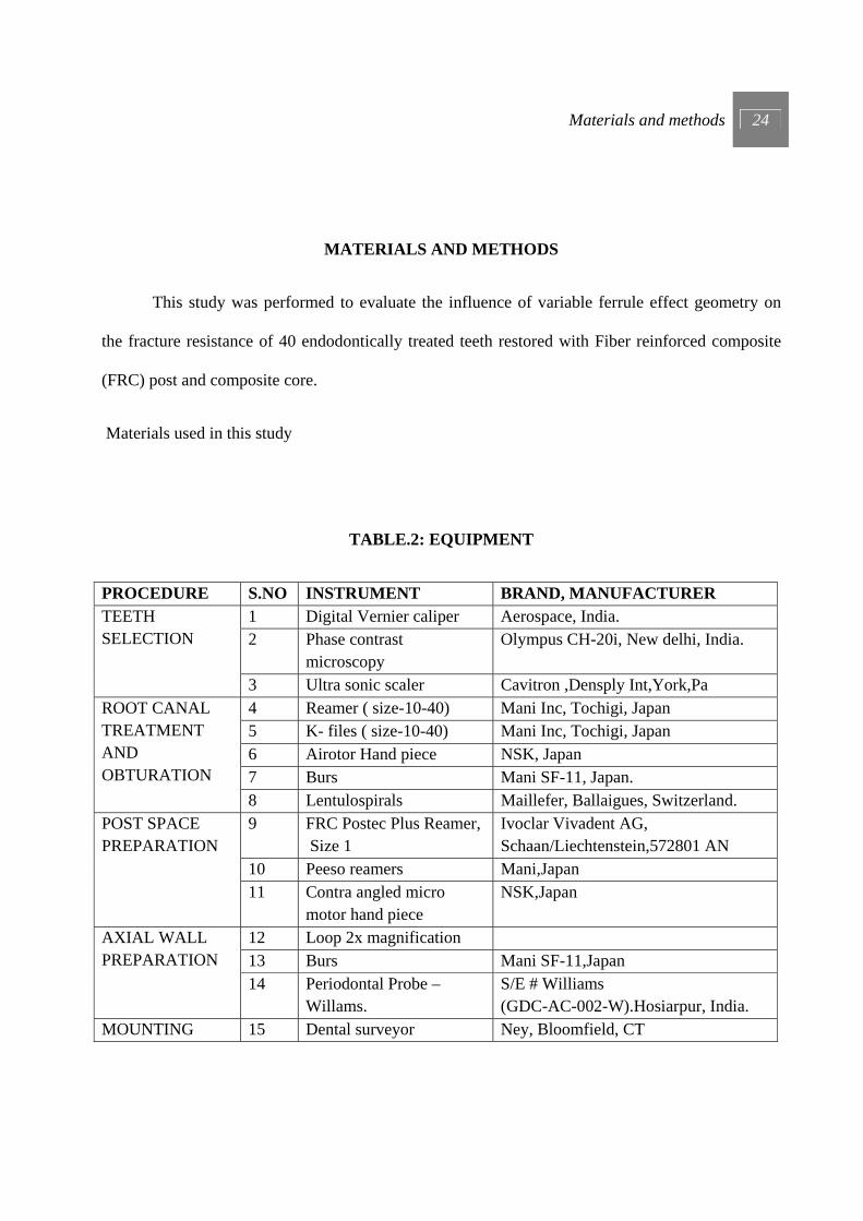
This study was performed to evaluate the influence of variable ferrule effect geometry on
the fracture resistance of 40 endodontically treated teeth restored with Fiber reinforced composite
(FRC) post and composite core.
Materials used in this study
TABLE.2: EQUIPMENT
PROCEDURE S.NO INSTRUMENT BRAND, MANUFACTURER TEETH SELECTION
1 Digital Vernier caliper Aerospace, India. 2 Phase contrast
microscopy Olympus CH-20i, New delhi, India.
3 Ultra sonic scaler Cavitron ,Densply Int,York,Pa ROOT CANAL TREATMENT AND OBTURATION
4 Reamer ( size-10-40) Mani Inc, Tochigi, Japan 5 K- files ( size-10-40) Mani Inc, Tochigi, Japan 6 Airotor Hand piece NSK, Japan 7 Burs Mani SF-11, Japan. 8 Lentulospirals Maillefer, Ballaigues, Switzerland.
POST SPACE PREPARATION
9 FRC Postec Plus Reamer, Size 1
Ivoclar Vivadent AG, Schaan/Liechtenstein,572801 AN
10 Peeso reamers Mani,Japan 11 Contra angled micro
motor hand piece NSK,Japan
AXIAL WALL PREPARATION
12 Loop 2x magnification 13 Burs Mani SF-11,Japan 14 Periodontal Probe –
Willams. S/E # Williams (GDC-AC-002-W).Hosiarpur, India.
MOUNTING 15 Dental surveyor Ney, Bloomfield, CT

Materials and methods 25
16 1 inch x 1 inch Stainless steel Cylinder
POST AND CORE BUILDUP
17 Light cure unit Hilux, First medica, USA
REFINING AXIAL PREPRATION WITH CORE
18 Custom made Airotor mounting Jig
19 Radiograph X mind, Germany
WAX PATTERN FABRICATION
20 Electric wax dropper WaxelectricII, Renfert, Germany
21 PKT instruments 22 Digital weighing machine Essae 23 Wax caliper
INVESTMENT AND CASTING
24 Vacuum mixer Easymix, Bego, Germany 25 Furnace Miditherm 100/200 MP,Bego, Gemany 26 Induction casting machine Fornax T,Bego, Germany 27 Metal trimmers Edenta, Switzerland 28 Lathe Ray foster,CA,USA 29 Sand blaster Korostar,Bego Germany 30 Metal caliper
CEMENTATION
31 2 kg Weight 32 Customized jig for crown
cementation
FRACTURE RESISTANCE
33 Custom made Acrylic block mounting Jig
34 Universal testing machine Instron 3382, London, UK CAMERA 35 Digital SLR Camera Nikon D5100 Japan
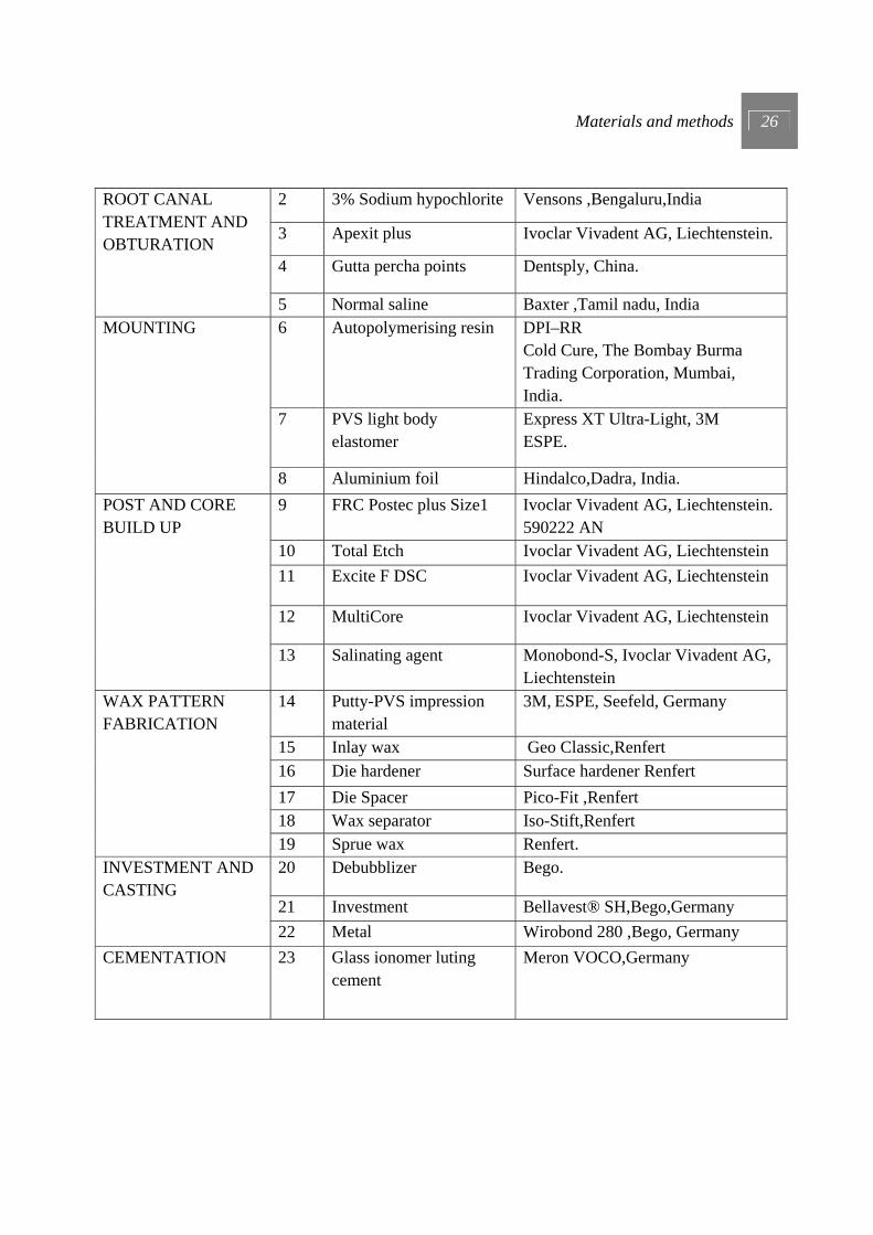
TABLE.3: MATERIALS
PROCEDURE S.No MATERIAL BRAND, MANUFACTURER
SELECTION OF TEETH
1 Thymol Nice Chemicals, Cochin, India
Materials and methods 26
ROOT CANAL TREATMENT AND OBTURATION
2 3% Sodium hypochlorite Vensons ,Bengaluru,India
3 Apexit plus Ivoclar Vivadent AG, Liechtenstein.
4 Gutta percha points Dentsply, China.
5 Normal saline Baxter ,Tamil nadu, India MOUNTING
6 Autopolymerising resin DPI–RR Cold Cure, The Bombay Burma Trading Corporation, Mumbai, India.
7 PVS light body elastomer
Express XT Ultra-Light, 3M ESPE.
8 Aluminium foil Hindalco,Dadra, India. POST AND CORE BUILD UP
9 FRC Postec plus Size1 Ivoclar Vivadent AG, Liechtenstein. 590222 AN
10 Total Etch Ivoclar Vivadent AG, Liechtenstein 11 Excite F DSC Ivoclar Vivadent AG, Liechtenstein
12 MultiCore Ivoclar Vivadent AG, Liechtenstein
13 Salinating agent Monobond-S, Ivoclar Vivadent AG, Liechtenstein
WAX PATTERN FABRICATION
14 Putty-PVS impression material
3M, ESPE, Seefeld, Germany
15 Inlay wax Geo Classic,Renfert 16 Die hardener Surface hardener Renfert 17 Die Spacer Pico-Fit ,Renfert 18 Wax separator Iso-Stift,Renfert 19 Sprue wax Renfert.
INVESTMENT AND CASTING
20 Debubblizer Bego.
21 Investment Bellavest® SH,Bego,Germany 22 Metal Wirobond 280 ,Bego, Germany
CEMENTATION 23 Glass ionomer luting cement
Meron VOCO,Germany
Materials and methods 27
METHODOLOGY
1) Selection of teeth.
2) Root canal preparation and obturation.
3) Post space preparation.
4) Grouping of samples.
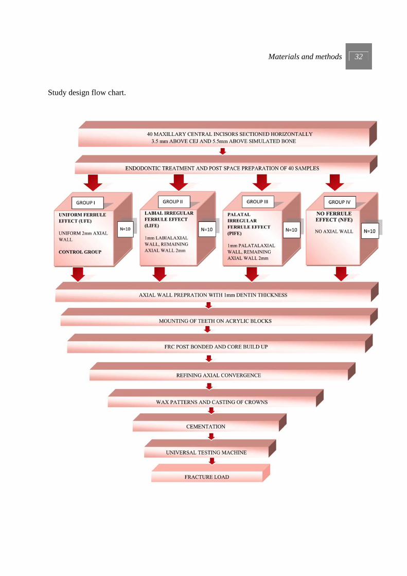
Group I (Control Group) - Uniform ferrule effect (UFE).
Group II - Labial irregular ferrule effect (LIFE).
Group III - Palatal irregular ferrule effect (PIFE).
Group IV - No ferrule effect (NFE).
5) Axial wall preparation for groups.
6) Mounting of teeth on acrylic blocks.
7) Bonding FRC post and core buildup.
8) Refining axial convergence.
9) Wax pattern fabrication.
10) Investing and casting
11) Cementation
12) Testing of specimens.
Materials and methods 28
1) SELECTION OF TEETH.
Fifty human maxillary central incisors devoid of caries, root canal fillings, restorations,
tooth wear and having root length between 11 mm to 13 mm 92,104 were obtained directly after
extraction. They were stored in 0.1% thymol solution during the course of the studyv14, 61. Hard and
soft tissue deposits were removed using ultra sonic instrumentation (Cavitron, Densply Int, York,
Pa). All selected teeth were examined under 220x magnifications in a phase contrast microscopy to
ensure that they had no abfractions, cracks or fracture lines 7.
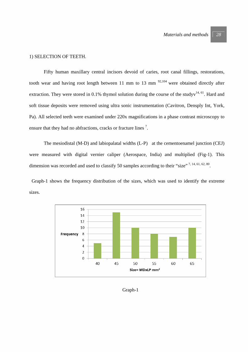
The mesiodistal (M-D) and labiopalatal widths (L-P) at the cementoenamel junction (CEJ)
were measured with digital vernier caliper (Aerospace, India) and multiplied (Fig-1). This
dimension was recorded and used to classify 50 samples according to their “size” 7, 14, 61, 62, 80.
Graph-1 shows the frequency distribution of the sizes, which was used to identify the extreme
sizes.
Graph-1

Materials and methods 29
Out of this 40 teeth of sizes between 40 - 60 mm2 were included for this study.
To ensure functional longevity, endodontically treated teeth must have at least 5 mm of
tooth structure coronal to the crestal bone 53, 54, 84. Three millimeters is needed to maintain a healthy
soft tissue complex (2mm connective tissue+1mm Junctional epithelium=Biologic width), and 2
mm of coronal tooth structure incisal to the preparation finish line is necessary to ensure structural
integrity 53 (axial wall for ferrule effect). To simulate this, the anatomic crowns of all 40 teeth were
removed perpendicular to the long axis of the tooth, 3.5mm above CEJ and 5.5 mm above
simulated bone level (Diagram-1), by using water-cooled diamond stone (Mani-SF11) at 300,000
rpm (NSK air turbine Japan).
2) ROOT CANAL PREPARATION AND OBTURATION.
Each canal was prepared to within 1mm of apex with a standard master apical file #25
(Mani, Japan).Master apical files of 3 larger sizes #30, #35, #40 were used for further preparation of
the canal 103. The root canal of each tooth was instrumented with a conventional step back
3.5mm ABOVE CEJ
5.5mm ABOVE SIMULATED BONE
Diagram-1
Materials and methods 30
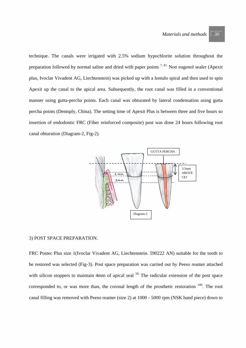
technique. The canals were irrigated with 2.5% sodium hypochlorite solution throughout the
preparation followed by normal saline and dried with paper points 7, 81. Non eugenol sealer (Apexit
plus, Ivoclar Vivadent AG, Liechtenstein) was picked up with a lentulo spiral and then used to spin
Apexit up the canal to the apical area. Subsequently, the root canal was filled in a conventional
manner using gutta-percha points. Each canal was obturated by lateral condensation using gutta
percha points (Dentsply, China). The setting time of Apexit Plus is between three and five hours so
insertion of endodontic FRC (Fiber reinforced composite) post was done 24 hours following root
canal obturation (Diagram-2, Fig-2).
3) POST SPACE PREPARATION.
FRC Postec Plus size 1(Ivoclar Vivadent AG, Liechtenstein. 590222 AN) suitable for the tooth to
be restored was selected (Fig-3). Post space preparation was carried out by Peeso reamer attached
with silicon stoppers to maintain 4mm of apical seal 59. The radicular extension of the post space
corresponded to, or was more than, the coronal length of the prosthetic restoration 100. The root
canal filling was removed with Peeso reamer (size 2) at 1000 - 5000 rpm (NSK hand piece) down to
Diagram-2
GUTTA PERCHA
3.5mm ABOVE CEJ
Materials and methods 31
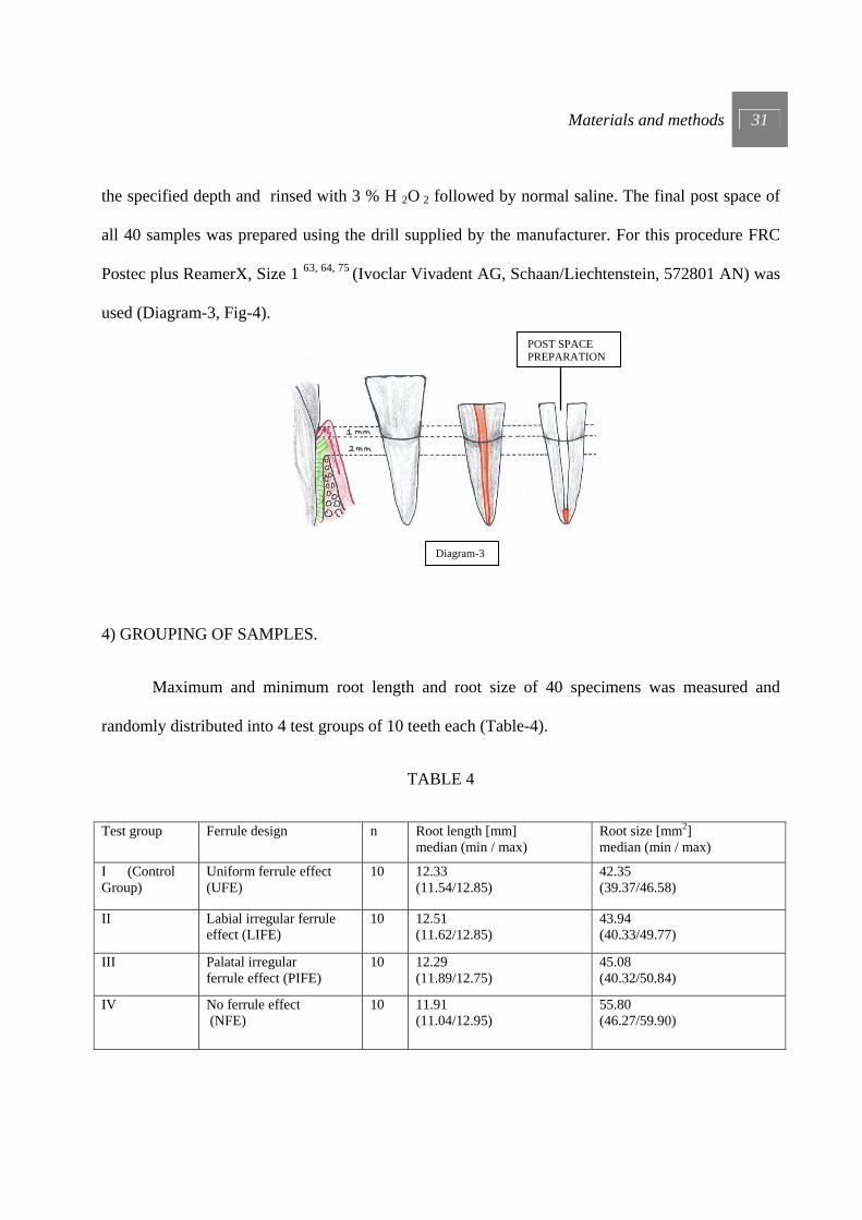
the specified depth and rinsed with 3 % H 2O 2 followed by normal saline. The final post space of
all 40 samples was prepared using the drill supplied by the manufacturer. For this procedure FRC
Postec plus ReamerX, Size 1 63, 64, 75 (Ivoclar Vivadent AG, Schaan/Liechtenstein, 572801 AN) was
used (Diagram-3, Fig-4).
4) GROUPING OF SAMPLES.
Maximum and minimum root length and root size of 40 specimens was measured and
randomly distributed into 4 test groups of 10 teeth each (Table-4).
TABLE 4
Test group Ferrule design n Root length [mm] median (min / max)
Root size [mm2] median (min / max)
I (Control Group)
Uniform ferrule effect (UFE)
10 12.33 (11.54/12.85)
42.35 (39.37/46.58)
II Labial irregular ferrule effect (LIFE)
10 12.51 (11.62/12.85)
43.94 (40.33/49.77)
III Palatal irregular ferrule effect (PIFE)
10 12.29 (11.89/12.75)
45.08 (40.32/50.84)
IV No ferrule effect (NFE)
10 11.91 (11.04/12.95)
55.80 (46.27/59.90)
POST SPACE PREPARATION
Diagram-3
Materials and methods 32
Study design flow chart.
Materials and methods 33
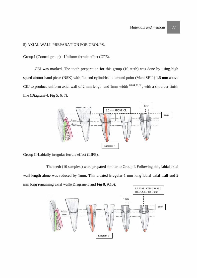
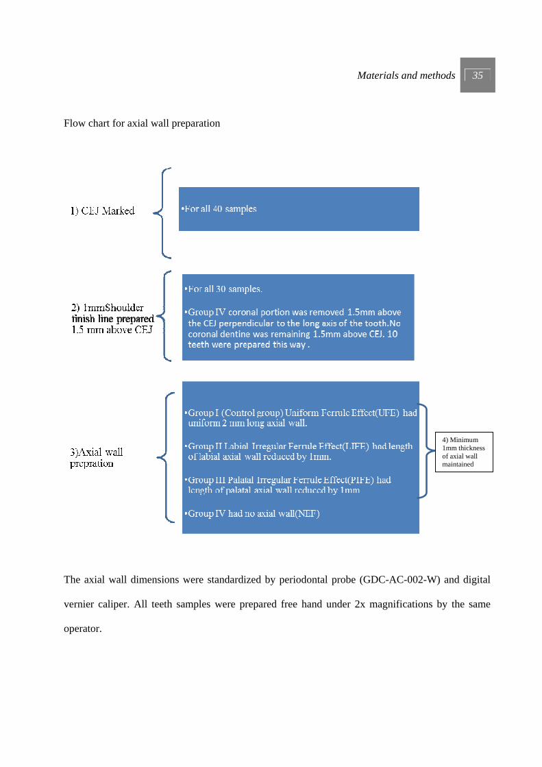
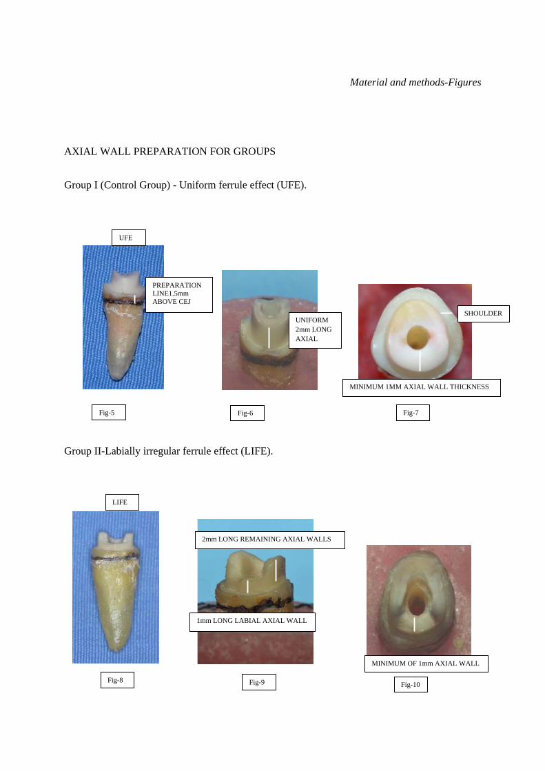
5) AXIAL WALL PREPARATION FOR GROUPS.
Group I (Control group) - Uniform ferrule effect (UFE).
CEJ was marked. The tooth preparation for this group (10 teeth) was done by using high
speed airotor hand piece (NSK) with flat end cylindrical diamond point (Mani SF11) 1.5 mm above
CEJ to produce uniform axial wall of 2 mm length and 1mm width 63,64,80,82 , with a shoulder finish
line (Diagram-4, Fig 5, 6, 7).
Group II-Labially irregular ferrule effect (LIFE).
The teeth (10 samples ) were prepared similar to Group I. Following this, labial axial
wall length alone was reduced by 1mm. This created irregular 1 mm long labial axial wall and 2
mm long remaining axial walls(Diagram-5 and Fig 8, 9,10).
1mm
2mm
LABIAL AXIAL WALL REDUCED BY 1 mm
Diagram-5
2mm
1mm
Diagram-4
3.5 mm ABOVE CEJ

Materials and methods 34
Group III-Palatal irregular ferrule effect (PIFE).
The teeth (10 samples) were prepared similar to Group I and then only palatal axial
wall was reduced by 1mm. This created irregular 1 mm long palatal axial wall and 2 mm long
remaining axial walls(Diagram-6 and Fig 11,12,13).
Group IV- No ferrule effect (NFE).
The coronal portion was removed 1.5mm above the CEJ perpendicular to the long axis of
the tooth by using high speed airotor hand piece (NSK) with flat end cylindrical diamond point
(Mani SF11). No coronal dentine was remaining 1.5mm above CEJ. 10 teeth were prepared this
way 63, 64,80 (Diagram-7, Fig 14, 15, 16).
PALATAL AXIAL WALL REDUCED BY 1 mm
1mm
2mm
Diagram-6
1.5 mm ABOVE CEJ
Diagram-4
Materials and methods 35
Flow chart for axial wall preparation
The axial wall dimensions were standardized by periodontal probe (GDC-AC-002-W) and digital
vernier caliper. All teeth samples were prepared free hand under 2x magnifications by the same
operator.
4) Minimum 1mm thickness of axial wall maintained
Materials and methods 36
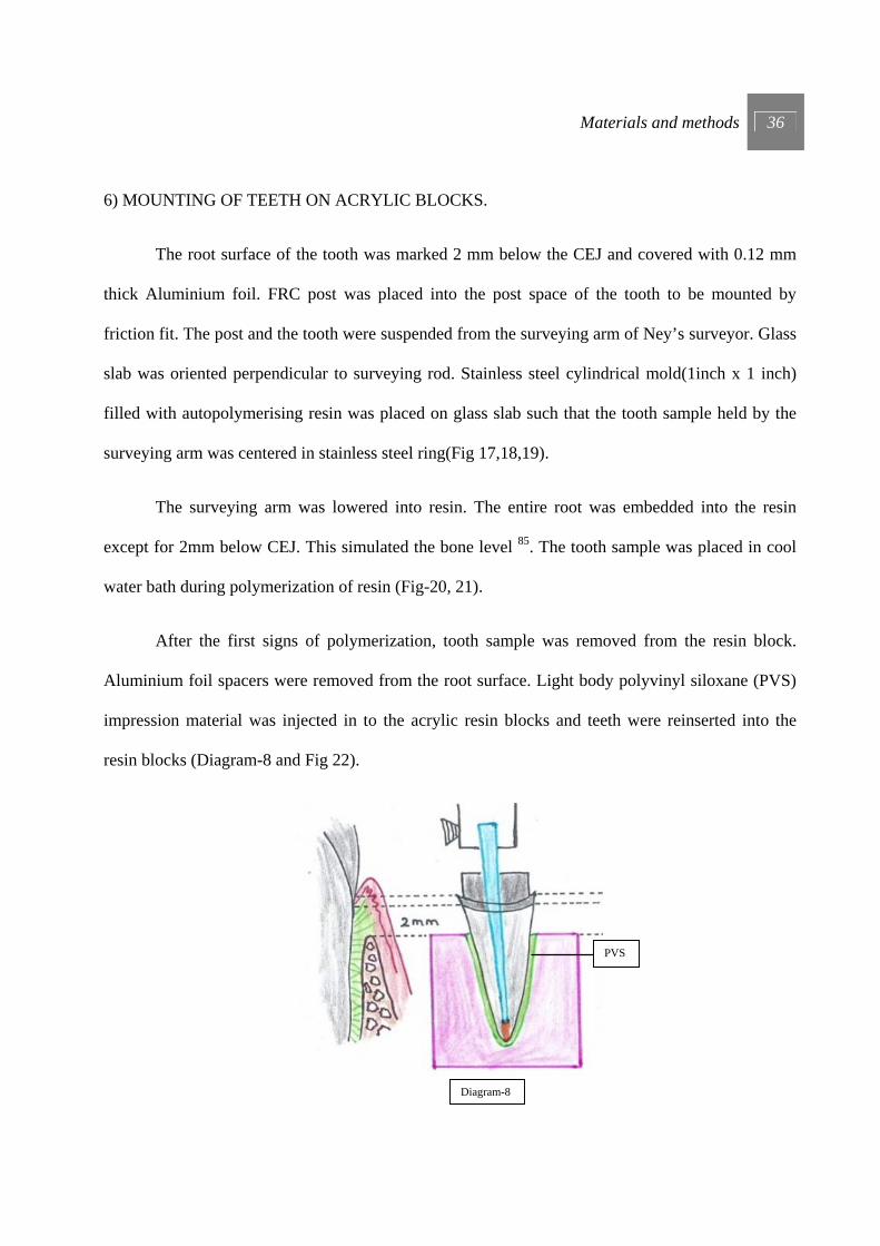
6) MOUNTING OF TEETH ON ACRYLIC BLOCKS.
The root surface of the tooth was marked 2 mm below the CEJ and covered with 0.12 mm
thick Aluminium foil. FRC post was placed into the post space of the tooth to be mounted by
friction fit. The post and the tooth were suspended from the surveying arm of Ney’s surveyor. Glass
slab was oriented perpendicular to surveying rod. Stainless steel cylindrical mold(1inch x 1 inch)
filled with autopolymerising resin was placed on glass slab such that the tooth sample held by the
surveying arm was centered in stainless steel ring(Fig 17,18,19).
The surveying arm was lowered into resin. The entire root was embedded into the resin
except for 2mm below CEJ. This simulated the bone level 85. The tooth sample was placed in cool
water bath during polymerization of resin (Fig-20, 21).
After the first signs of polymerization, tooth sample was removed from the resin block.
Aluminium foil spacers were removed from the root surface. Light body polyvinyl siloxane (PVS)
impression material was injected in to the acrylic resin blocks and teeth were reinserted into the
resin blocks (Diagram-8 and Fig 22).
Diagram-8
PVS

Materials and methods 37
A standardized silicone layer was formed over root surface to simulate periodontal ligament. In this
manner mounting for the remaining samples was completed 1, 52, 66 .
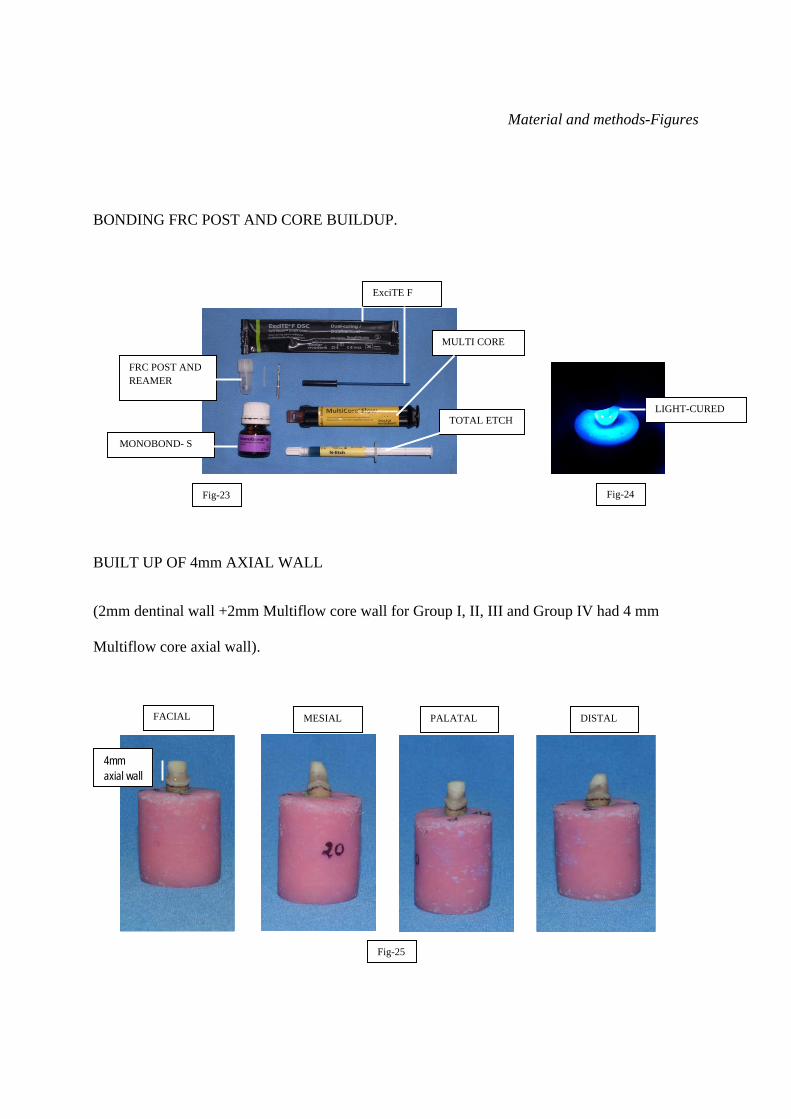
7) BONDING FRC POST AND CORE BUILDUP.
FRC post was bonded to post space by direct method under following steps.
a) Try-in and conditioning of FRC Postec Plus.
Proper fit of the post was checked. After determining the coronal length the post was
shortened using rotary diamond grinders. Then post was etched with phosphoric acid
etching gel (Total Etch) for 60 seconds. FRC Postec Plus post was thoroughly rinsed with
water and dried. After silanateing the post (Monobond-S) for 60 seconds, it was carefully
dried with an air syringe. Care was taken so as not to touch the surface with fingers after
that (Fig-23).
b) Conditioning of post space.
Phosphoric acid gel (Total Etch) was applied to the prepared post space and axial
walls of tooth. The etchant should be left to react for 10-15 seconds. Following this, the
etchant was thoroughly removed with a vigorous water spray for at least 5 seconds. Excess

Materials and methods 38
moisture was removed leaving the surface with a glossy wet appearance (wet bonding). This
can be done with paper points. Care was taken so as to not over dry the dentine.
c) Adhesive cementation of post with a dual curing composite.
- ExciTE F DSC (contains HEMA, dimethacrylate, phosphonic acid acrylate,
dispersed silicone dioxide, initiators, stabilizers and potassium fluoride in an alcohol
solution) was applied to the enamel and dentin and agitated for 10 sec making sure that all
prepared walls are completely covered.
- The components of MultiCore Flow was mixed and applied to the post. The post
was seated into the root canal and held in place using slight pressure.
– Light-curing for 60 seconds from the occlusal aspect using a curing unit with a
light intensity more than 400 mW/cm2 was done. The light emission window was positioned
as close to the post as possible (Fig 24).
d) Core build-up using MultiCore Flow.
Multicore Flow was applied directly on top of post and axial walls and core built up was
done to achieve an axial wall height of 4mm. That is 2mm of axial wall and 2mm of Multi
flow core 76, 81 (Fig 25). The material was light-cured; and ground immediately after
completing the curing cycle. The distance between the light emission window and the

Materials and methods 39
occlusal surface was kept at a minimum. Further curing was done for 40 seconds.
Radiographs were taken to ensure correct placement of post 59, 71 (4mm above apex) (Fig26).
RECAP-
8) REFINING AXIAL CONVERGENCE.
A jig was fabricated to hold airotor to Ney’s surveyor so that long axis of bur parallels to the
long axis of surveyor arm (Diagram-10).
40 teeth samples
RCT Post space preparation
Group I UFE n=10
Mounting 40 teeth samples
Group-I UFE
with core n=10
Diagram-9
Group II LIFE n=10
Group III PIFE n=10
Group IV NFE n=10
Group-II LIFE
with core n=10
Group-III PIFE
with core n=10
Group-IV NFE
with core n=10

Materials and methods 40
Mounted specimen was refined to provide uniform axial convergence. A bur (Mani SF11) was
fitted to airotor and specimen was refined so as to provide parallel walls (Fig 27, 28). 40 specimens
were refined in this manner (Fig 29).
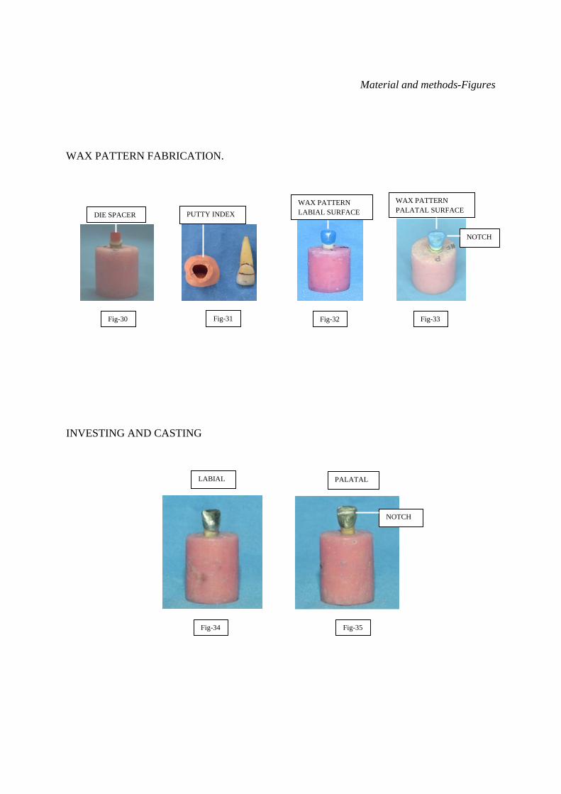
9) WAX PATTERN FABRICATION.
Wax patterns for the crowns were formed directly on tooth specimens coated with die spacer
(Pico fit, Renfert) 12 to 15 micron thickness and a lubricant (Iso-Stift,Renfert) was applied(Figure-
30). Wax patterns (Geo classic, Renfert) were formed using a vinyl polysiloxane impression
material (Putty 3M) mold made from one natural tooth (Fig 31, 32, 33).This mold was used in
fabricating all wax crown patterns. A standardized notch was placed across the palatal surface of
each crown 3 mm from the incisal edge. This notch was carved into the wax patterns to
accommodate the loading device of the universal testing machine, which has a blade-shaped
configuration with a straight flat surface shaped to simulate the incisal edge of a mandibular incisor
63,80.
Diagram-10

Materials and methods 41
10) INVESTING AND CASTING
The wax patterns were sprued, debubblizer applied and invested in high expansion
phosphate-bonded investment material (Bellavest SH,Bego ,Germany) and cast using non-precious
metal alloy free of nickel and beryllium (Wirobond 280, Bego,Germany). Casting was sand blasted
and sprues sectioned with carborundum disc. Cast crowns were adjusted with fit checker until they
were fully passively seated 63 (Fig 34, 35).
11) CEMENTATION
The cast crowns were cemented with glass ionomer luting cement (Meron, Voco, Germany)
under 20 newton’s of load for 10 min 63,81 (Fig36, 37). Excess cement was removed and 40 samples
(Fig 38) were stored in 100% humidity at room temperature for 30 days before testing 80.
12) TESTING OF SPECIMENS.
Each sample was placed in a testing Jig which angulates the samples to 135° for testing
fracture resistance (Fig 39, 40). A universal testing machine with load cell having maximum
capacity of 1000N(Instron 3382, London, UK) was used to apply a compressive load to tooth
specimens with a cross head speed of 1mm/min at an angle of 135° using angulated testing jig to
the long axis of teeth,until fracture occurred (Fig 41,42) 2, 80, 63.
Labially inclined compressive force was applied to the notch on the palatal surface of the
crowns simulating the load applied by mandibular incisor. Force data applied over time was
recorded . The fracture of the specimen was determined when the force versus time graph showed
abrupt change in load,indicating a sudden decrease in the specimens resistance to compressive
loading.Specimens were visually examined for the type , location and direction of fracture.

Material and methods-Figures
FIGURES
SELECTION OF TEETH
ROOT LENGTH BETWEEN 11-13 mm
M-D WIDTH AT CEJ L-P WIDTH AT CEJ
Fig-1
5.5mm ABOVE SIMULATED BONE
3.5 mm ABOVE CEJ
Material and methods-Figures
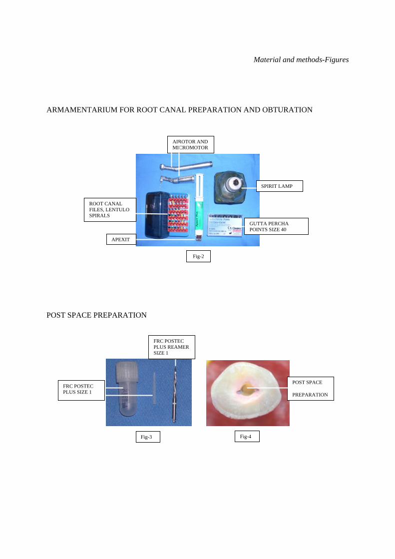
ARMAMENTARIUM FOR ROOT CANAL PREPARATION AND OBTURATION
POST SPACE PREPARATION
Fig-2
Fig-3
POST SPACE
PREPARATION
Fig-4
FRC POSTEC PLUS SIZE 1
FRC POSTEC PLUS REAMER SIZE 1
AIROTOR AND MICROMOTOR
ROOT CANAL FILES, LENTULO SPIRALS
APEXIT
GUTTA PERCHA POINTS SIZE 40
SPIRIT LAMP
Material and methods-Figures
AXIAL WALL PREPARATION FOR GROUPS
Group I (Control Group) - Uniform ferrule effect (UFE).
Group II-Labially irregular ferrule effect (LIFE).
Fig-8 Fig-9 Fig-10
1mm LONG LABIAL AXIAL WALL
2mm LONG REMAINING AXIAL WALLS
MINIMUM OF 1mm AXIAL WALL
PREPARATION LINE1.5mm ABOVE CEJ
Fig-5
UNIFORM 2mm LONG AXIAL
Fig-6
SHOULDER
MINIMUM 1MM AXIAL WALL THICKNESS
Fig-7
LIFE
UFE

Material and methods-Figures
Group III-Palatal irregular ferrule effect (PIFE).
Group IV- No ferrule effect (NFE).
Fig-11 Fig-12 Fig-13
1mm LONG PALATAL AXIAL WALL
SHOULDER
MINIMUM 1mm AXIAL WALL
1.5 mm ABOVE CEJ
Fig-14 Fig-15 Fig-16
NFE
PIFE

Material and methods-Figures
MOUNTING OF TEETH ON ACRYLIC BLOCKS.
Fig-17 Fig-18 Fig-19
2mm BELOW CEJ SIMULATED BONE LEVEL
Fig-21 Fig-20 Fig-22
PVS
FRC POSTEC PLUS SIZE 1
ALUMINIUM FOIL ON ROOT
STAINLESS STEEL CYLINDRICAL MOLD (1INCH X 1 INCH)
AUTOPOLYMERISING RESIN
Material and methods-Figures
BONDING FRC POST AND CORE BUILDUP.
BUILT UP OF 4mm AXIAL WALL
(2mm dentinal wall +2mm Multiflow core wall for Group I, II, III and Group IV had 4 mm
Multiflow core axial wall).
Fig-23 Fig-24
FACIAL MESIAL PALATAL DISTAL
4mm axial wall
Fig-25
TOTAL ETCH
FRC POST AND REAMER
MONOBOND- S
ExciTE F
MULTI CORE
LIGHT-CURED
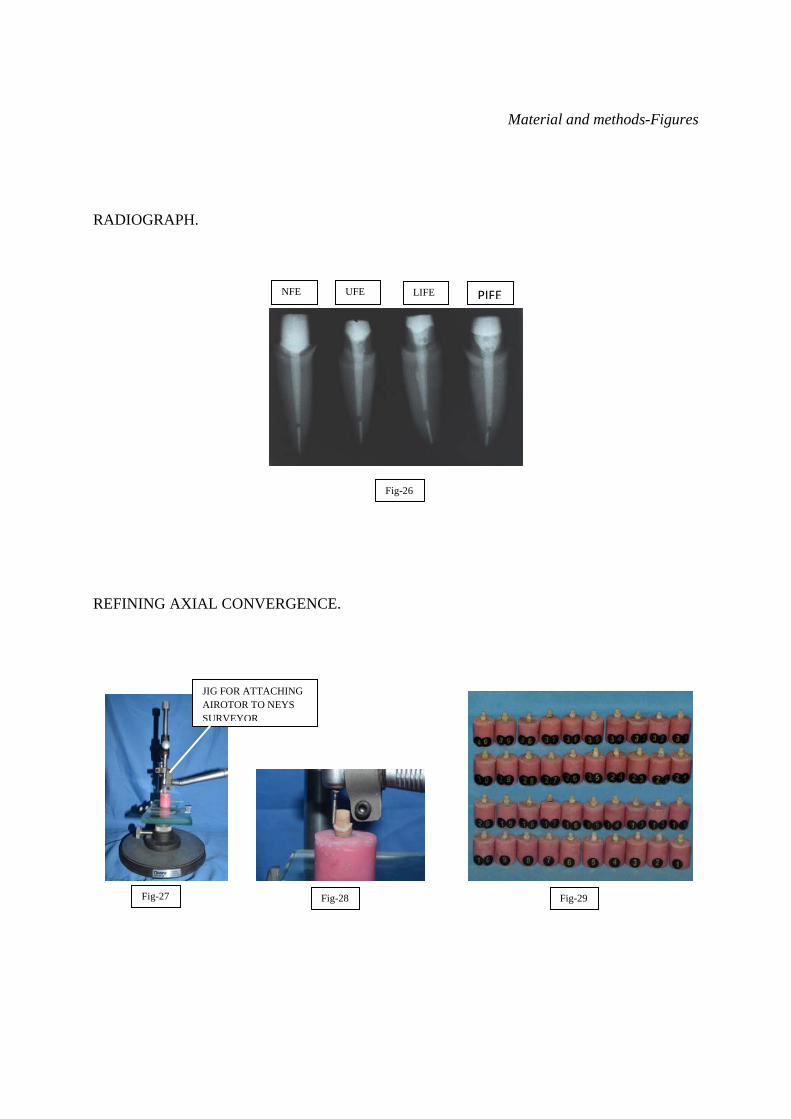
Material and methods-Figures
RADIOGRAPH.
REFINING AXIAL CONVERGENCE.
Fig-26
NFE UFE LIFE PIFE
Fig-28 Fig-27 Fig-29
JIG FOR ATTACHING AIROTOR TO NEYS SURVEYOR
Material and methods-Figures
WAX PATTERN FABRICATION.
INVESTING AND CASTING
Fig-30 Fig-31 Fig-32 Fig-33
LABIAL PALATAL
Fig-34 Fig-35
NOTCH
DIE SPACER
WAX PATTERN LABIAL SURFACE
WAX PATTERN PALATAL SURFACE
NOTCH
PUTTY INDEX

Material and methods-Figures
CEMENTATION
40 TEETH SAMPLES
Fig-36 Fig-37
Fig-38
JIG FOR CEMENTATION WITH 2Kg WEIGHT
EXCESS CEMENT

Material and methods-Figures
TESTING OF SPECIMENS
Fig-39 Fig-40
Fig-41 Fig-42
ANGULATED AT 135°
STAINLESS STEEL MOULD -1INCH X 1 INCH
JIG FOR 135° ANGULATION
AUTOPOLYMERISING RESIN
TOOTH SAMPLE
UNIVERSAL TESTING MACHINE
FRACTURE OF SPECIMEN
STEEL ROD SIMULATING MANDIBULAR INCISOR FITTING TO PALATAL NOTCH
135°
Material and methods-Figures
RESULT
R-A R-B R-C NR-B NR-A
Fig-43
R-A R-B R-C NR-B NR-A
Fig-44

RESULT

Results 42
RESULT
This study was conducted
1} To compare fracture resistance of endodontically treated teeth, with and without ferrule effect.
2} To compare fracture resistance of endodontically treated teeth having uniform 2mm ferrule
effect with non-uniform ferrule effect.
3} To compare fracture resistance of endodontically treated teeth having nonuniform palatal and
nonuniform labial ferrule effect.
All the 40 samples were tested with universal testing machine at a cross-head speed of 1
mm/min with the load applied at 135°using the specimen holder. The stainless-steel stylus was
shaped to mimic mandibular incisor and was used to test failure resistance and failure load was
recorded in Newton’s (N).
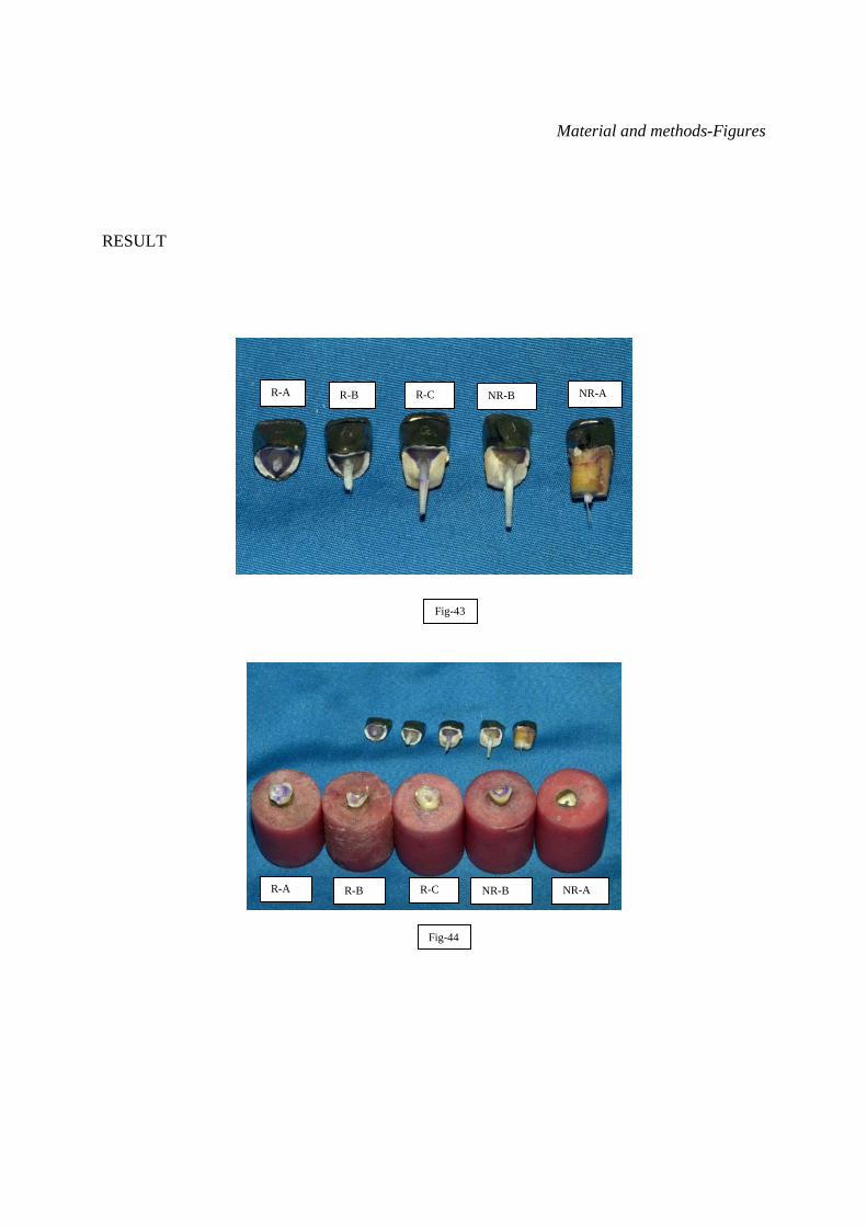
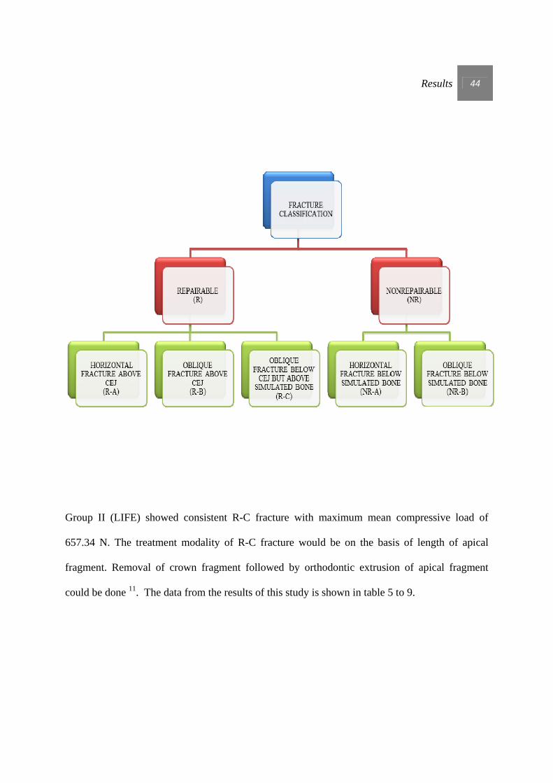
Failures that occurred under fracture testing were classified into repairable and non-
repairable in relation to simulated bone. When fracture occurs below simulated bone the
remaining apical fragment cannot be used for prosthetic reconstruction and considered non-
repairable. In fracture occurring above simulated bone the remaining apical fragment could be
used for reconstruction after orthodontic extrusion or by crown lengthening, hence considered
repairable.

Results 43
I - Repairable (including tooth fractures and adhesive failures of the core) when the fracture line
was above the simulated bone level (Fig 43 and 44).
- Repairable horizontal fracture above CEJ (R-A).
- Repairable oblique fracture above CEJ (R-B).
- Repairable oblique fracture below CEJ but above simulated bone(R-C).
II - Nonrepairable (including root fracture) when the fracture line was below the simulated bone
level (Fig 43 and 44).
- Nonrepairable horizontal fracture below simulated bone (NR-A).
- Nonrepairable oblique fracture below simulated bone (NR-B).
Results 44
Group II (LIFE) showed consistent R-C fracture with maximum mean compressive load of
657.34 N. The treatment modality of R-C fracture would be on the basis of length of apical
fragment. Removal of crown fragment followed by orthodontic extrusion of apical fragment
could be done 11. The data from the results of this study is shown in table 5 to 9.

Results 45
TABLE 5-FRACTURE RESISTANCE OF ENDODONTICALLY TREATED CENTRAL INCISOR WITH UNIFORM FERRULE EFFECT (UFE) GROUP-I.
TOOTH NUMBER
MAXIMUM
COMPRESSIVE LOAD
(NEWTONS-N)
COMPRESSIVE
STRENGTH Mpa
F-L
WIDTH mm
M-D
WIDTH mm
ROOT SIZE mm2
ROOT
LENGTH
FRACTURE – IN RELATION TO CEJ AND SIMULATED BONE
LABIAL
PALATAL
CLASSIFICATION
POST
1 568.81 12.46 6.83 6.51 44.46 12.85 2mm BELOW
CEJ
1.5 mm ABOVE
CEJ
R-C DEBONDING AND BREAKAGE
2 480.47 13.10 6.20 6.58 40.80 12.82 4mm BELOW
CEJ
4mm BELOW
CEJ
NR-B BREAKAGE
3 561.12 12.05 6.84 6.81 46.58 12.70 2mm BELOW
CEJ
1.5 mm ABOVE
CEJ
R-C DEBONDING AND BREAKAGE
4 621.98 15.46 6.45 6.24 40.25 11.54 3mm BELOW
CEJ
4mm BELOW
CEJ
NR-A BREAKAGE
5 511.17 11.70 6.89 6.34 43.68 12.84 2mm BELOW
CEJ
1.5 mm ABOVE
CEJ
R-C DEBONDING AND BREAKAGE
6 520.49 13.39 6.35 6.45 40.96
12.43 2mm BELOW
CEJ
1.5 mm ABOVE
CEJ
R-C BREAKAGE
7 557.64 12.86 6.65 6.52 43.36 12.14 2mm BELOW
CEJ
1.5 mm ABOVE
CEJ
R-C DEBONDING AND BREAKAGE
8 490.47 13.27 5.95 6.81 40.52 12.12 1.5 mm ABOVE
CEJ
1 mm ABOVE
CEJ
R-A BREAKAGE
9 530.64 13.48 6.23 6.32 39.37 11.64 2mm BELOW
CEJ
1.5 mm ABOVE
CEJ
R-C DEBONDING AND BREAKAGE
10 510.15 11.74 6.76 6.43 43.47 12.21 2mm BELOW
CEJ
1.5 mm ABOVE
CEJ
R-B DEBONDING AND BREAKAGE
AVERAGE
535.29 12.95 6.52 6.50 42.35 12.33
Tooth samples of UFE (Group-I) showed average maximum compressive load of 535.29 N and tooth fractures were mostly repairable 80 %( R). Non-repairable fracture (NR) was 20%.

Results 46
TABLE 6 - FRACTURE RESISTANCE OF ENDODONTICALLY TREATED CENTRAL INCISOR WITH LABIAL IRREGULAR FERRULE EFFECT (LIFE) GROUP-II.
TOOTH NUMBER
MAXIMUM COMPRESSIVE LOAD (NEWTONS-N)
COMPRESSIVE STRENGTH Mpa
F-L WIDTH mm
M-D WIDTH mm
ROOT SIZE mm2
ROOT LENGTH
FRACTURE – IN RELATION TO CEJ AND SIMULATED BONE LABIAL
PALATAL
CLASSIFICATION
POST
11 584.82 12.63 6.70 6.91 46.30 12.57 2mm BELOW CEJ
1.5 mm ABOVE CEJ
R-C DEBONDING AND BREAKAGE
12 731.38 16.80 6.21 7.01 43.53 12.67 2mm BELOW CEJ
1.5 mm ABOVE CEJ
R-C DEBONDING AND BREAKAGE
13 708.14 16.53 7.32 5.85 42.82 11.62 2mm BELOW CEJ
1.5mm BELOW CEJ
R-C DEBONDING AND BREAKAGE
14 638.59 15.83 6.12 6.59 40.33 12.46 2mm BELOW CEJ
1.5mm ABOVE CEJ
R-C DEBONDING AND BREAKAGE
15 573.24 14.21 6.13 6.58 40.34 12.72 2mm BELOW CEJ
1.5 mm ABOVE CEJ
R-C DEBONDING AND BREAKAGE
16 690.44 16.60 6.32 6.58 41.59 12.51 2mm BELOW CEJ
1.5 mm ABOVE CEJ
R-C DEBONDING AND BREAKAGE
17 625.29 14.74 6.23 6.81 42.43 12.80 2mm BELOW CEJ
1.5 mm ABOVE CEJ
R-C DEBONDING AND BREAKAGE
18 720.56 15.34 6.73 6.98 46.98 12.43 2mm BELOW CEJ
1.5 mm ABOVE CEJ
R-C DEBONDING AND BREAKAGE
19 710.54 14.28 6.98 7.13 49.77 12.45 2mm BELOW CEJ
1.5 mm ABOVE CEJ
R-C DEBONDING AND BREAKAGE
20 590.49 13.03 6.53 6.94 45.32 12.85 2mm BELOW CEJ
1.5 mm ABOVE CEJ
R-C DEBONDING AND BREAKAGE
AVERAGE
657.34 15 6.53 6.74 43.94 12.51
Tooth samples of LIFE (Group-II) showed average maximum compressive load 657.34 N and all fractures were repairable (R) 100%.
Results 47
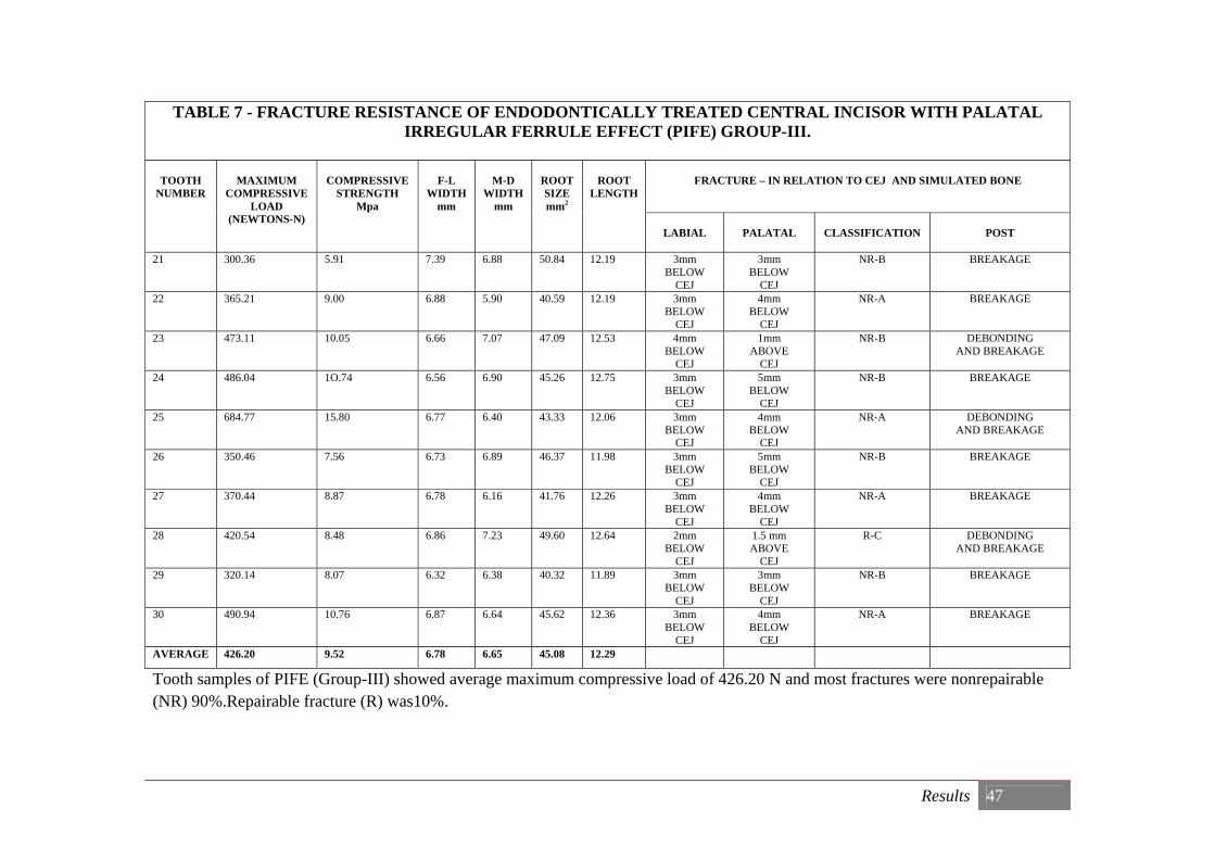
TABLE 7 - FRACTURE RESISTANCE OF ENDODONTICALLY TREATED CENTRAL INCISOR WITH PALATAL IRREGULAR FERRULE EFFECT (PIFE) GROUP-III.
TOOTH NUMBER
MAXIMUM
COMPRESSIVE LOAD
(NEWTONS-N)
COMPRESSIVE
STRENGTH Mpa
F-L
WIDTH mm
M-D
WIDTH mm
ROOT SIZE mm2
ROOT
LENGTH
FRACTURE – IN RELATION TO CEJ AND SIMULATED BONE
LABIAL
PALATAL
CLASSIFICATION
POST
21 300.36 5.91 7.39 6.88 50.84 12.19 3mm BELOW
CEJ
3mm BELOW
CEJ
NR-B BREAKAGE
22 365.21 9.00 6.88 5.90 40.59 12.19 3mm BELOW
CEJ
4mm BELOW
CEJ
NR-A BREAKAGE
23 473.11 10.05 6.66 7.07 47.09 12.53 4mm BELOW
CEJ
1mm ABOVE
CEJ
NR-B DEBONDING AND BREAKAGE
24 486.04 1O.74 6.56 6.90 45.26 12.75 3mm BELOW
CEJ
5mm BELOW
CEJ
NR-B BREAKAGE
25 684.77 15.80 6.77 6.40 43.33 12.06 3mm BELOW
CEJ
4mm BELOW
CEJ
NR-A DEBONDING AND BREAKAGE
26 350.46 7.56 6.73 6.89 46.37 11.98 3mm BELOW
CEJ
5mm BELOW
CEJ
NR-B BREAKAGE
27 370.44 8.87 6.78 6.16 41.76 12.26 3mm BELOW
CEJ
4mm BELOW
CEJ
NR-A BREAKAGE
28 420.54 8.48 6.86 7.23 49.60 12.64 2mm BELOW
CEJ
1.5 mm ABOVE
CEJ
R-C DEBONDING AND BREAKAGE
29 320.14 8.07 6.32 6.38 40.32 11.89 3mm BELOW
CEJ
3mm BELOW
CEJ
NR-B BREAKAGE
30 490.94 10.76 6.87 6.64 45.62 12.36 3mm BELOW
CEJ
4mm BELOW
CEJ
NR-A BREAKAGE
AVERAGE 426.20 9.52 6.78 6.65 45.08 12.29
Tooth samples of PIFE (Group-III) showed average maximum compressive load of 426.20 N and most fractures were nonrepairable (NR) 90%.Repairable fracture (R) was10%.
Results 48
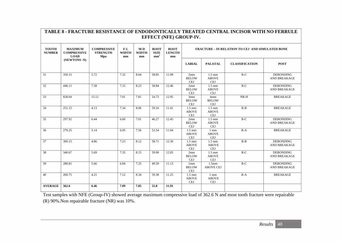
TABLE 8 - FRACTURE RESISTANCE OF ENDODONTICALLY TREATED CENTRAL INCISOR WITH NO FERRULE EFFECT (NFE) GROUP-IV.
TOOTH NUMBER
MAXIMUM
COMPRESSIVE LOAD
(NEWTONS -N)
COMPRESSIVE
STRENGTH Mpa
F-L
WIDTH mm
M-D
WIDTH mm
ROOT SIZE mm2
ROOT
LENGTH mm
FRACTURE – IN RELATION TO CEJ AND SIMULATED BONE
LABIAL
PALATAL
CLASSIFICATION
POST
31 350.15 5.72 7.32 8.04 58.85 11.99 2mm BELOW
CEJ
1.5 mm ABOVE
CEJ
R-C DEBONDING AND BREAKAGE
32 446.11 7.58 7.15 8.23 58.84 12.46 2mm BELOW
CEJ
1.5 mm ABOVE
CEJ
R-C DEBONDING AND BREAKAGE
33 828.04 15.12 7.01 7.81 54.75 12.95 3mm BELOW
CEJ
4mm BELOW
CEJ
NR-H BREAKAGE
34 251.15 4.13 7.34 8.06 59.16 11.41 1.5 mm ABOVE
CEJ
1.5 mm ABOVE
CEJ
R-B BREAKAGE
35 297.92 6.44 6.60 7.01 46.27 12.45 2mm BELOW
CEJ
1.5 mm ABOVE
CEJ
R-C DEBONDING AND BREAKAGE
36 270.25 5.14 6.95 7.56 52.54 11.04 1.5 mm ABOVE
CEJ
1 mm ABOVE
CEJ
R-A BREAKAGE
37 300.15 4.86 7.23 8.12 58.71 12.36 1.5 mm ABOVE
CEJ
1.5 mm ABOVE
CEJ
R-B DEBONDING AND BREAKAGE
38 340.67 5.69 7.35 8.15 59.90 12.05 2mm BELOW
CEJ
1.5 mm ABOVE
CEJ
R-C DEBONDING AND BREAKAGE
39 280.81 5.66 6.84 7.25 49.59 11.13 1mm BELOW
CEJ
1.5mm ABOVE CEJ
R-C DEBONDING AND BREAKAGE
40 260.75 4.21 7.12 8.34 59.38 11.25 1.5 mm ABOVE
CEJ
1 mm ABOVE
CEJ
R-A BREAKAGE
AVERAGE 362.6 6.46 7.09 7.85 55.8 11.91
Test samples with NFE (Group-IV) showed average maximum compressive load of 362.6 N and most tooth fracture were repairable (R) 90%.Non repairable fracture (NR) was 10%.
Result 49
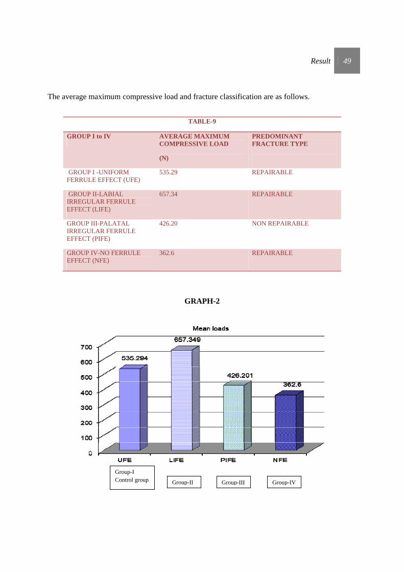
The average maximum compressive load and fracture classification are as follows.
TABLE-9
GROUP I to IV AVERAGE MAXIMUM COMPRESSIVE LOAD
(N)
PREDOMINANT FRACTURE TYPE
GROUP I -UNIFORM FERRULE EFFECT (UFE)
535.29 REPAIRABLE
GROUP II-LABIAL IRREGULAR FERRULE EFFECT (LIFE)
657.34 REPAIRABLE
GROUP III-PALATAL IRREGULAR FERRULE EFFECT (PIFE)
426.20 NON REPAIRABLE
GROUP IV-NO FERRULE EFFECT (NFE)
362.6 REPAIRABLE
GRAPH-2
Group-I Control group Group-II Group-III Group-IV
Result 50
STATISTICAL ANALYSIS
From the results obtained, the mean values were calculated. These results were subjected
to statistical analysis to test the study hypothesis.
NULL HYPOTHESIS-
There is no significant difference in fracture resistance between UFE (Control group),
NFE, LIFE, PIFE based on mean compressive loading.
ALTERNATE HYPOTHESIS-
There is significant difference between the four groups based on mean loading
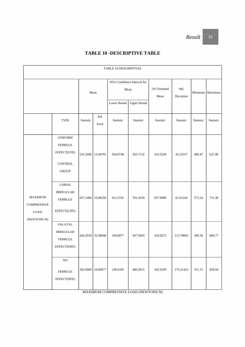
Result 51
TABLE 10 -DESCRIPTIVE TABLE
TABLE 10-DESCRIPTIVES
Mean
95% Confidence Interval for
Mean 5% Trimmed
Mean
Std.
Deviation Minimum Maximum
Lower Bound Upper Bound
TYPE Statistic Std.
Error Statistic Statistic Statistic Statistic Statistic Statistic
MAXIMUM
COMPRESSIVE
LOAD
(NEWTONS-N)
UNIFORM
FERRULE
EFFECT(UFE)
CONTROL
GROUP
535.2940 13.44701 504.8748 565.7132 533.5239 42.52317 480.47 621.98
LABIAL
IRREGULAR
FERRULE
EFFECT(LIFE)
657.3490 19.48356 613.2741 701.4239 657.9089 61.61243 573.24 731.38
PALATAL
IRREGULAR
FERRULE
EFFECT(PIFE)
426.2010 35.98040 344.8077 507.5943 418.8272 113.78003 300.36 684.77
NO
FERRULE
EFFECT(NFE)
362.6000 54.80677 238.6185 486.5815 342.9339 173.31423 251.15 828.04
MAXIMUM COMPRESSIVE LOAD (NEWTONS-N)
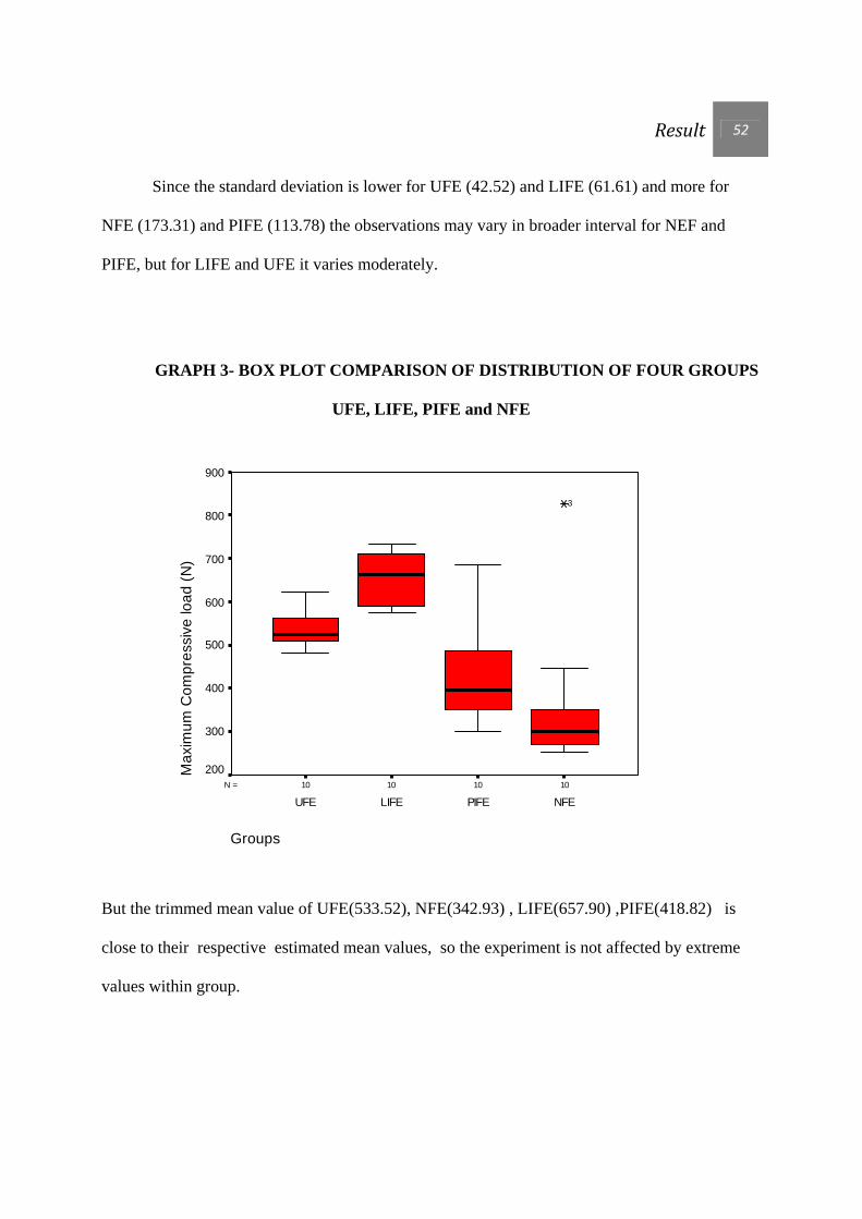
Result 52
Since the standard deviation is lower for UFE (42.52) and LIFE (61.61) and more for
NFE (173.31) and PIFE (113.78) the observations may vary in broader interval for NEF and
PIFE, but for LIFE and UFE it varies moderately.
GRAPH 3- BOX PLOT COMPARISON OF DISTRIBUTION OF FOUR GROUPS
UFE, LIFE, PIFE and NFE
10101010N =
Groups
NFEPIFELIFEUFE
Max
imum
Com
pres
sive
load
(N)
900
800
700
600
500
400
300
200
3
But the trimmed mean value of UFE(533.52), NFE(342.93) , LIFE(657.90) ,PIFE(418.82) is
close to their respective estimated mean values, so the experiment is not affected by extreme
values within group.

Result 53
One way Anova and Tukey HSD tests (t-test) were done.
One-way analysis of variance (ANOVA) tests is used to compare more than two groups
based on their average scores. The total variations among the observations are split between
groups’ variations and within group variations, and the comparison is made. If the between group
variation is considerably larger than within group variation, then there is a statistical significance
for mean differences.
TABLE 11-ANOVA FOR
MAXIMUM COMPRESSIVE LOAD (NEWTONS-N)
TABLE 11-ANOVA
MAXIMUM COMPRESSIVE LOAD (NEWTONS-N)
Sum of Squares df Mean Square F
Sig.
p
Between Groups 502433.454 3 167477.818 13.788 .000
Within Groups 437292.260 36 12147.007
Total 939725.714 39
Result 54
Statistical inference (From Table 11) -
Since p value is less than 0.01 (1% level of significance), the null hypothesis is proven
wrong and the test favors alternative hypothesis that there is significant difference between the
four groups based on mean loading.
In ANOVA when the null hypothesis is rejected, conclusion is that all group means are
not equal. But the test does not indicate the comparative equality of pairs of means. Therefore
Post Hoc tests are applied.
Tukey’s Honesty Significant Difference (HSD) is one among the post –hoc test
methods to do multiple pairwise comparisons. If the difference between two group’s means is
considerably bigger than the general variation, then it is inferred that there is a significant
difference.
Since there is a significant difference among groups, Tukey’s HSD (Post-hoc) test is
employed to compare the groups pairwise based on mean values. The t statistic values and p
values are given in Table 12.

Result 55
TABLE 12-TUKEY HSD TESTS
Table 12-Multiple Comparisons
Dependent Variable: MAXIMUM COMPRESSIVE LOAD (NEWTONS-N) Tukey HSD
Mean Difference
(I-J) Std. Error
p
(I) TYPE (J) TYPE
UNIFORM FERRULE EFFECT (UFE / GROUP-I)
NFE 172.6940(*) 49.28896 .007
LIFE -122.0550(#) 49.28896 .081
PIFE 109.0930 49.28896 .139
LABIAL IRREGULAR FERRULE
EFFECT (LIFE /GROUP-II)
NFE 294.7490(*) 49.28896 .000
UFE 122.0550(#) 49.28896 .081
PIFE 231.1480(*) 49.28896 .000
PALATAL IRREGULAR FERRULE
EFFECT (PIFE / GROUP III)
NFE 63.6010 49.28896 .575
UFE -109.0930 49.28896 .139
LIFE -231.1480(*) 49.28896 .000
NO FERRULE EFFECT (NFE / GROUP IV)
UFE -172.6940(*) 49.28896 .007
LIFE -294.7490(*) 49.28896 .000
PIFE -63.6010 49.28896 .575
* The mean difference is significant at the 0 .05 level (5%).
#The mean difference is significant at 0.10 level (10%).
Result 56
Since most of the p value in Table 12 is less than 10% and 5%, the null hypothesis is
proven wrong. The results favour alternative hypothesis.
This infers that with regard to fracture resistance
1) UFE is statistically significant from NFE by 5% (p0.007) and LIFE by10 %( p 0.081)
2) LIFE is statistically significant from NFE by 1 %( p 0.000), PIFE by1 %( p 0.000) and UFE
by10% (p 0.081).
3) PIFE is statistically significant from LIFE by 1% (p0.000).
4) NFE is statistically significant from UFE by 5% (p 0.007) and LIFE by 1 %( p 0.000).
DISCUSSION
Discussion 57
DISCUSSION
Restoring endodontically treated maxillary central incisor is a complex procedure because of
multifactorial ramifications. The condition of the tooth and occlusal forces acting on it along
with a wide array of materials available to restore usually puzzles the treatment modality.
Preservation of tooth tissue, presence of a ferrule effect, and adhesion are regarded as the most
effective conditions for long-term success of post-endodontic restorations 32.
This study aims at comparing uniform ferrule effect (2mm axial wall) with
irregular ferrule effect (1mm labial axial wall or 1mm palatal axial wall) and no ferrule effect
(absence of axial wall).
In order to prosthodontically restore endodontically treated maxillary central incisors,
2 parameters should be considered;
Parameter 1 - Minimum tooth structure required to go ahead with restoration.
Parameter 2 - Ideal restorative materials.
Parameter 1- Minimum tooth structure required to go ahead with restoration.
Mc Lean 53 stated that for a tooth to be successfully restored there must be a minimum of
4.5 mm of solid tooth structure above the bone crest; given that a minimum of 2.5 mm is
required for biologic width and 2 mm for an effective ferrule.

Discussion 58
Sivers JE 83 defined biologic width as the dimension of the Junctional epithelial and
connective tissue attachment to the root above the alveolar crest. This distance has been
established as approximately 1 mm for the Junctional epithelium and 1 mm for the connective
tissue attachment. An additional millimeter within the gingival crevice is necessary to allow for
the establishment of the restorative margin. Therefore, when a subgingival defect is restored, a
minimum of 3 mm of sound tooth structure coronal to the alveolar crest is necessary.
DeSort 24 defined ferrule effects, as a metal ring or cap put around the end of a
tool, cane, etc., to give added strength. This effect is used in endodontically treated teeth to
reinforce the coronal aspect of the dowel preparation by aiding in effective occlusal seat 34.
The term ferrule is often misinterpreted. It is used as an expression of the amount of
remaining sound dentine above the finish line. It is infact not the remaining tooth structure that is
the ‘ferrule’ but rather the actual bracing of the complete crown over the tooth structure that
constitutes the ferrule effect, i.e. the protection of the remaining tooth structure against fracture63.
360° coverage of crown, on tooth / root structure is required for ferrule effect 44, 45, 89, 90.
This constitutes to 360° coverage by ferrule in restorative crown + presence of 360° 2mm
long axial wall on tooth or root = ferrule effect (Diagram-11). In this study teeth samples of
control group are made to simulate 360° ferrule effect.

Discussion 59
In clinical situations, the location of remaining coronal tooth structure is not a
controllable factor, as it is dictated by the condition of the tooth after trauma, endodontic
treatment and caries removal. Due to this there is irregularity of circumferential coronal tooth
structure, and difficulty in obtaining uniform 360° ferrule effect. Available literature favours
uniform 2mm axial wall for ferrule effect. Clinical experience shows that when a tooth fractured
due to trauma it often follows a pattern. Occlusal overload may cause facial sub-gingival tooth
damage and leave palatal hard tissue intact. Perpendicular loading to the facial surface
commonly results in a palatal sub-gingival level fracture. Under these circumstances obtaining
uniform 2mm axial wall is difficult 60, 74, 96, 103.
Ideally, a fractured tooth should be classified before preparation, with the desired finished
preparation in mind. This assists the practitioner to make adjustments to preserve maximum
thickness and height of the remaining tooth structure during preparation. Peroz et al 68 has
FERRULE ON METAL CROWN
CONTINIOUS AXIAL WALL
RED ZONE MARKS FERRULE EFFECT
Diagram-11
Discussion 60
classified clinical crown loss and restorations required, on the basis of remaining axial cavity
walls. He stated that a dentine thickness greater than 1mm provides an amount of hard tissue
sufficient to stabilize the core material even after crown preparation. Jotkowitz and Samet 44 had
classified the amount of remaining tooth structure that can be incorporated into the ferrule effect,
so that the risk of mechanical failure can be judged and appropriate treatment options can be
selected. In the present study, dentin of minimum 1mm thickness and 2mm axial wall (cavity
wall) length has been maintained for uniform ferrule effect group.
Various different ferrule designs have been suggested but currently there is little research
supporting one design over the other 87. Most publications discuss the required height of ferrule,
however, other design characteristics like dentine thickness, location of the remaining dentine
walls, and the load the restoration has to withstand, were not considered.
Parameter 2- Ideal restorative materials.
Didier Dietschi 25, 26 stated that since no finding suggest that the natural dentin is an
inappropriate core material, the use of materials with dentin like properties currently appears to
be the most suitable approach. Resin-fiber posts currently are preferred option because they have
physical properties closer to dentin than do metals or ceramics. Adhesively luted fiber-reinforced
composite post restorations have demonstrated satisfactory survival rates over long follow-up
periods. The clinical effectiveness of such restorations had been mainly ascribed to the more
biomimetic behavior of fiber reinforced composite posts that reduces the risk of vertical root
fractures 16, 83. Owing to a greater similarity in elastic properties with dentine, FRC posts allow

Discussion 61
for a relatively uniform stress distribution to the tooth and the surrounding tissues, thus yielding
a protective effect against root fracture 23, 32, 37,60 .
Posts can be bonded to tooth structure with resin luting agents. It has been postulated that
this allows the formation of a cohesive unit between tooth, post, and core 63. This concept of the
monobloc configuration further increases fracture resistance.
Posts are frequently used for the retention of a core material in teeth that have had
extensive loss of coronal tooth structure 18. Their use, however, may increase root fracture due to
excessive pressures during insertion or because of lateral movement of the post within the root,
thus ironically increases the risk of root fracture 35, 98 and failure 86.Therefore, the use of a correct
ferrule design is of utmost importance for teeth restored with post and cores. Since placing crown
margins significantly subgingivally is not advisable because of the violation of biologic width,
the quest for the perfect ferrule may lead to the incorporation of treatments like crown
lengthening and/or an orthodontic extrusion45, 86 .Clearly, this presents a dilemma as crown
lengthening surgery may result in a poorer crown to root ratio and also compromised the
aesthetics with loss of the inter-dental papilla and a potential loss of the support of the adjacent
teeth. Orthodontic intervention may resolve some of these risks, however, the crown to root ratio
may still be compromised and it is time consuming with an additional fee to the whole
procedure, making it non-feasible in many cases 12. For this reason it becomes necessary to
explore the existing parameters of the ferrule effect as it stands in the literature.
In this study, specimens represent restored maxillary anterior teeth. The fracture
resistance of the specimens is a function of bond strength (between post/core/crown and
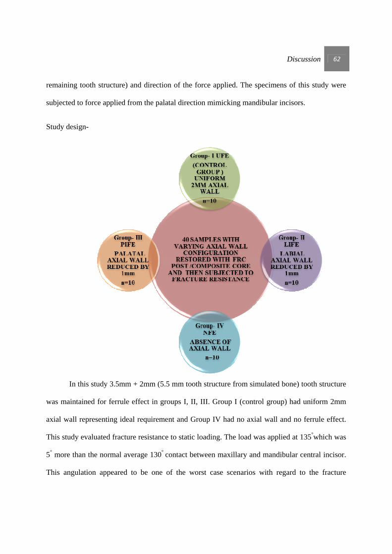
Discussion 62
remaining tooth structure) and direction of the force applied. The specimens of this study were
subjected to force applied from the palatal direction mimicking mandibular incisors.
Study design-
In this study 3.5mm + 2mm (5.5 mm tooth structure from simulated bone) tooth structure
was maintained for ferrule effect in groups I, II, III. Group I (control group) had uniform 2mm
axial wall representing ideal requirement and Group IV had no axial wall and no ferrule effect.
This study evaluated fracture resistance to static loading. The load was applied at 135°which was
5° more than the normal average 130° contact between maxillary and mandibular central incisor.
This angulation appeared to be one of the worst case scenarios with regard to the fracture
Discussion 63
resistance of endodontically treated teeth and was considered suitable for evaluating the
biomechanical behavior of fiber-post restorations in Group IV samples 43, 87.
The results of this investigation confirms the general consensus that a uniform 2-mm
ferrule is superior to the lack of a ferrule in the prevention of tooth fracture under a static load 91
The average maximum compressive load in newton’s (N) for Group I-UFE (Control group) is
532.29N, Group II – LIFE is 657.34 N, Group III -PIFE is 426.20N and Group IV-NFE is
362.6N.
The reported maximal occluding force for males exerted by a maxillary incisor tooth is
146 + or - 44 N 91 Even though forces in this study were above 146 N, teeth in Group IV without
a ferrule effect (362.6 N) are at risk of fracture when compared with Group I uniform 2 mm
ferrule effect (532.29N). This observation leads to the conclusion that there is substantial benefit
in providing a ferrule whenever possible.
To the question –Which ferrule effect configuration would resist fracture more? The
answer seems to favor Labial irregular ferrule effect (LIFE) with 657.34N. This Group II (LIFE)
sample has shown maximum fracture resistance with an average of 122.05N more than Control
Group I (UFE). The Group III (PIFE) with 426.20N shows more fracture resistance than Group
IV (NFE) but significantly less than Group I (UFE) and Group II (LIFE). Group IV (NFE) with
362.6N showed the least fracture resistance.
In this study LIFE is highly significant from NFE and PIFE (mean differences 294.7490
and 231.1480) with p value (0.000) less than 5%. In-between UFE and LIFE since p value
(0.081) is less than 10%, it may be inferred that there is a moderate level significance (mean

Discussion 64
difference of 122.0550). There is no significant difference between the pairs NFE and PIFE; and
UFE and PIFE.
Ng et al 63 had stated that when the remaining axial wall is at the location where the load
is applied, the arc of displacement of complete crown places the remaining tooth structure under
tension. In contrast if the remaining axial wall is on the labial aspect, with no palatal wall the arc
of displacement affects the bond between the post and core first, followed by the strength of
remaining tooth structure. With no coronal tooth structure remaining, the resistance to
displacement is primarily a function of the bond between the post/core and the remaining tooth.
To study this arc of displacement Group I (UFE) to Group IV (NFE) samples were used. Results
obtained from this study are consistent with the above stated study (Diagram-12).
Diagram-12
D D DD
UFE LIFE PIFE NFE
Arc of displacement of crown. (A) fulcrum (B) arc of crown displacement(C) bond strength of post /core to root (D) direction of force.
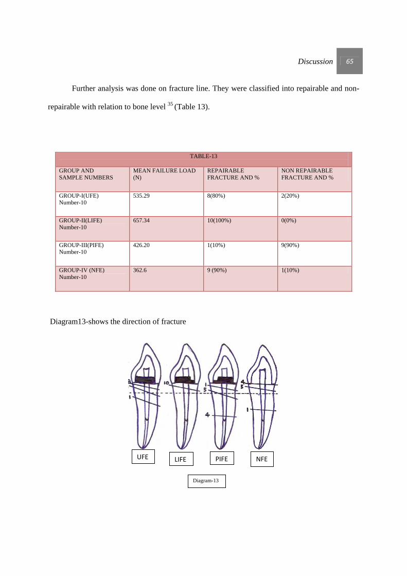
Discussion 65
Further analysis was done on fracture line. They were classified into repairable and non-
repairable with relation to bone level 35 (Table 13).
TABLE-13 GROUP AND SAMPLE NUMBERS
MEAN FAILURE LOAD (N)
REPAIRABLE FRACTURE AND %
NON REPAIRABLE FRACTURE AND %
GROUP-I(UFE) Number-10
535.29 8(80%) 2(20%)
GROUP-II(LIFE) Number-10
657.34 10(100%) 0(0%)
GROUP-III(PIFE) Number-10
426.20 1(10%) 9(90%)
GROUP-IV (NFE) Number-10
362.6 9 (90%) 1(10%)
Diagram13-shows the direction of fracture
NFE UFE LIFE PIFE
Diagram-13

Discussion 66
In this study Group III (PIFE) shows maximum non-repairable fracture and Group II
(LIFE) showed maximum repairable fracture. Group II is the most favourable in terms of
fracture resistance this could be because the labial irregularity increases the bonding surface area
and also due to the presence of intact 2mm palatal axial wall buttressing the arc of displacement.
It could be postulated that specimens restored with fiber reinforced post systems offered more
homogenous stress distribution due to their modulus of elasticity close to that of dentin resulting
in a better stress distribution that occurs at the post-dentin interface 32 .Conversely, titanium,
stainless steel and zirconia have elastic moduli (110 GPa, 200 GPa, 300 GPa, respectively) well
above that of dentine (18 GPa). In the presence of rigid posts, stress is transmitted internally and
concentrates towards the apical level, thus increasing the risk for vertical root fracture that
represents a catastrophic failure 25, 26, 62, 32.This could explain why in this study all favourable
fractures were limited to the cervical portion of the root including the core-dentin interface, since
the stresses were concentrated in the cervical area and the outer root surface.
Group II showed consistent R-C type of fracture .There is a feasibility of treating them
again, depending on the available length of apical fragment. The coronal fragment is removed
and crown lengthening could be done 12, 84.
The mean fracture resistance was more than 400 Newton in all groups except for NFE,
which was more than the force that causes fracture clinically 52, 61, 101. As the fracture loads in all
groups in the present study were found to be greater than the ordinary chewing force, and
maximum biting force, their mechanical strength could be considered satisfactory from a clinical
point of view due to the choice of post material 81.The results also indicated that LIFE is more
effective at resisting fracture than a tooth with NFE and UFE. If a maxillary central incisor
Discussion 67
initially does not have sufficient axial wall, an attempt should be made to allow for at least 2 mm
palatal axial wall.
In a similar study carried out by Ng et al 63 in 2006, the impact of five types of ferrule
preparation was examined on the mean fracture resistance. The result is consistent with the result
of this study (i.e.) palatal axial wall is important in fracture resistance in endodontically treated
maxillary central incisor.
In a study carried out by Naumann et al 61 they concluded that the absence of portions of
a crown ferrule (missing facial or palatal aspects, proximal interrupted) is associated with greater
variation of failure load and strength values might be reduced to below a clinically acceptable
load bearing. This result was in contrast to the present study. In the present study continuous
axial wall was preserved and strength values were more in LIFE.
Based on a report by Torbjorner and colleagues, anterior teeth will sustain fracture as a
result of tension and not compression 96 .A palatal loading on maxillary anterior teeth may cause
stress in the form of tension in the palatal margin and may also cause stress in the form of
compression in the facial margin 10, 52. Therefore, the first marginal and cervical opening will be
visible in the palatal area 10 which can explain the different types of fracture in this study.
Bone support and the periodontal ligament are important for the mechanisms of stress
distribution over teeth. In this study PDL simulation was done with Light bodied PVS material
and bone simulation was done with acrylic resin. Soares 85 stated that greater influence of
periodontal ligament simulation is noted on the fracture mode rather than on the fracture load
values. In his study the teeth embedded in acrylic resin or polystyrene resin without periodontal
Discussion 68
ligament simulation tended to fracture on the top of the resin cylinders, while the teeth with
periodontal ligament simulation tended to fracture in different locations with a greater prevalence
towards root portion. Fracture locations found in this study correlate with Soares study, fracture
with partial invasion below CEJ and above simulated bone (R-C type fracture).
The primary mode of failure for NFE, UFE, LIFE, and PIFE groups was coronal root
fracture. This suggested that a cohesive relationship existed between the tooth, post, core, and
crown. The resin bond between the different restorative components in these 4 groups appears to
have been sufficient to resist fracture of the post or debonding from the root, which is the most
common mechanism of clinical failure for endodontically treated teeth 86, 87, 100 .
It is important to note that the type of testing used that is, a single cycle to failure does
not represent the intraoral condition. Intraorally, teeth are subject to loading through mastication
and are in a wet environment that is subject to chemical and thermal changes. This study design
examined angle and force from a single direction, and this design is not necessarily
representative of clinical conditions. The study also simulated maxillary central incisors, and
therefore, the results can be applied only to that group of teeth. The results of this in vitro study,
however, show that in the absence of 360° of circumferential coronal tooth structure, the location
of remaining axial tooth structure incisal to the preparation finish line may be an important factor
for determining the fracture resistance of restored endodontically treated teeth.
Future research with cyclical loading to closely simulate clinical conditions can be
explored. Cast posts and cores could also be compared with prefabricated posts and cores to
determine differences under simulated clinical conditions. Future research can also be done with
varying thickness of axial wall.
SUMMARY AND CONCLUSION
Summary and conclusion 69
SUMMARY
Literature on endodontically treated teeth state that 2mm uniform ferrule effect, is ideal
for fracture resistance. In clinical situations it is rare to have uniform 2mm ferrule effect.
This in-vitro study was conducted to evaluate varied ferrule effect geometry on the
fracture resistance of endodontically treated maxillary central incisors. A total number of forty
extracted maxillary central incisors were selected for this study. Teeth samples were divided into
4 groups of 10 teeth each. Group I (Control group) was compared with Group II (LIFE), Group
III (PIFE) and Group IV (NFE).
These teeth samples were mounted on acrylic blocks.FRC posts were bonded and
composite core built up was done. Metal crowns were cemented with type I glass ionomer
cement. The restored teeth samples were loaded on a universal testing machine at an angulation
of 135° by using custom made jig for fracture testing. The results were subjected to one way
ANOVA and HSD TUKEY test to analyze the statistical significance.
The results of this study revealed that uniform 2mm ferrule increased fracture resistance.
Due importance must be given to preserve the palatal axial wall (i.e.) in the absence of uniform
2mm axial wall at least 1mm labial axial wall and 2mm of remaining axial walls should be
preserved when treating endodontically treated maxillary central incisor.
Summary and conclusion 70
CONCLUSION
Within the limitations of this study, the following conclusions can be drawn.
1. Uniform ferrule effect and Labial irregular ferrule effect increased the failure threshold.
2. Palatal axial wall had profound effect on fracture resistance and in the absence of uniform
2mm axial wall, maximum 2mm palatal axial wall with minimum 1mm labial axial wall
increased the fracture resistance.
3. Insertion of a fiber post could reduce the percentage of catastrophic failure.

BIBLIOGRAPHY
Bibliography 71
BIBLIOGRAPHY
1. Akkayan B, Gülmez. Resistance to fracture of endodontically treated teeth restored with
different post systems. J Prosthet Dent 2002; 87(4):431-7.
2. Akkayan B. An in vitro study evaluating the effect of ferrule length on fracture resistance
of endodontically treated teeth restored with fiber-reinforced and zirconia dowel systems.
J Prosthet Dent 2004; 92(2):155-62.
3. Al-Hazaimeh N, Gutteridge DL. An in vitro study into the effect of the ferrule
preparation on the fracture resistance of crowned teeth incorporating prefabricated post
and composite care restoration. Int endod J 2001; 34(1): 40-6.
4. Al-Omiri MK, Al-Wahadni AM. An ex vivo study of the effects of retained coronal
dentine on the strength of teeth restored with composite core and different post and core
systems. Int Endod J 2006; 39:890–9.
5. Al-Omiri MK, Mahmoud AA. Fracture resistance of teeth restored with post-retained
restorations: an overview. J Endod 2010; 36(9):1439-49.

Bibliography 72
6. Al-Wahadni A, Gutteridge D L. An in vitro investigation into the effects of retained
coronal dentine on the strength of a tooth restored with a cemented post and partial core
restoration. Int Endod J 2002; 35: 913-918.
7. Arunpraditkul S, Saengsanon S. Fracture resistance of endodontically treated teeth: three
walls versus four walls of remaining coronal tooth structure. J Prosthodont 2009; 18: 49-
53.
8. Assif D. et al. Photoelastic analysis of stress transfer by endodontically treated teeth to
the supporting structure using different restorative techniques J Prosthet Dent 1989;
61(5):535-43.
9. Assif D. et al. Effect of post design on resistance to fracture of endodontically treated
teeth with complete crowns. J Prosthet Dent 1993; 69(1):36-40.
10. Assif D, Gorfil C. Biomechanical considerations in restoring endodontically treated teeth.
J Prosthet Dent 1994; 71(6):565-7.
11. Barkhordar RA, Radke R, Abbasi J. Effect of metal collars on resistance of
endodontically treated teeth to root fracture. J Prosthet Dent1989; 61(6):676-8.
12. Berman LH, Blanco L, Cohen S.A clinical guide to dental traumatology.2007 Mosby-
Elseveer. Chapter 4, Pg-51-69.

Bibliography 73
13. Buttel L, Krastl G. Influence of post fit and post length on fracture resistance. Int Endod J
2009; 42(1):47-53.
14. Butz F, Lennon AM, Heydecke G, Strub JR. Survival rate and fracture strength of
endodontically treated maxillary incisors with moderate defects restored with different
post-and-core systems: an in vitro study. Int J Prosthodont 2001; 14(1):58-64.
15. Cagidiaco MC, Radovic I. Clinical performance of fiber post restorations in
endodontically treated teeth: 2-year results. Int J Prosthodont 2007; 20(3):293-8.
16. Cathro PR, Chandler N P, Hood J A. Impact resistance of crowned endodontically
treated central incisors with internal composite cores. Endod Dent Traumatol 1996;
12(3):124-8.
17. Cho H, Michalakis K X. Impact of interproximal groove placement and remaining
coronal tooth structure on the fracture resistance of endodontically treated maxillary
anterior teeth. J Prosthodont 2009; 18: 43–48.
18. Christensen GJ. When to use fillers, build-ups or posts and cores. J Am Dent Assoc 1996;
127(9):1397-8.

Bibliography 74
19. Christensen GJ. Posts: necessary or unnecessary? J Am Dent Assoc 1996;
127(10):1522-4.
20. Creugers NHJ, Kreulen CM.A 5-year prospective clinical study on core restorations
without covering crowns. Int J Prosthodont 2005a; 18:40-41.
21. Creugers NHJ, Kreulen CM. 5-year follow-up of a prospective clinical study on various
types of core restorations. Int J Prosthodont 2005b; 18:34-39.
22. Da Silva NR et al. The effect of post, core, crown type, and ferrule presence on the
biomechanical behavior of endodontically treated bovine anterior teeth. J Prosthet Dent
2010; 104:306-317.
23. de Castro Albuquerque R, Polleto LT. Stress analysis of an upper central incisor restored
with different posts. J Oral Rehabil. 2003; 30(9):936-43.
24. DeSort KD. The prosthodontic use of endodontically treated teeth: theory and
biomechanics of post preparation. J Prosthet Dent. 1983; 49(2):203-6.
25. Didier Dietschi et al. Biomechanical considerations for the restoration of endodontically
treated teeth: A systematic review of the literature-Part 1. Composition and micro- and
macrostructure alterations. Quintessence Int 2007; 38:733–743.
Bibliography 75
26. Didier Dietschi et al. Biomechanical considerations for the restoration of endodontically
treated teeth: A systematic review of the literature, Part II (Evaluation of fatigue
behavior, interfaces, and in vivo studies). Quintessence Int 2008; 39:117–129.
27. Erslan O, Aykent F. The finite element analysis of the effect of ferrule height on stress
distribution at post and core restored all ceramic anterior crowns. Clin Oral Invest 2009
13:223–227.
28. Ferrari M, Vichi A, Mannocci F. Retrospective study of the clinical performance of fiber
posts. Am J Dent. 2000; 13:9B-13B.
29. Ferrari M, Cagidiaco MC. Post placement affects survival of endodontically treated
premolar. J Dent Res 2007; 86(8):729-734.
30. Gegauff A. G. Effect of crown lengthening and ferrule placement on static load failure of
cemented cast post-cores and crowns. J Prosthet Dent 2000; 84(2):169-79.
31. Goldberg IS, Slutzky H. Restoration of endodontically treated teeth review and treatment
recommendations. Int J Dent2009; 2009:150251.
32. Goracci C, Ferrari M. Current perspectives on post systems: a literature review. Aust
Dent J. 2011; 56(1):77-83.

Bibliography 76
33. Gutmann JL. The dentin-root complex: anatomic and biologic considerations in restoring
endodontically treated teeth. J Prosthet Dent 1992; 67(4):458-67.
34. Hemmings KW, King PA, Setchell DJ. Resistance to torsional forces of various post and
core designs.J Prosthet Dent 1991; 66(3):325-9.
35. Heydecke G,Butz F.Fracture Strength and survival rate of endodontically treated
maxillary incisors with approximal cavities after restoration with different post and core
systems: an in vitro study. J Dent. 2001; 29(6):427-33.
36. Heydecke G, Peters, M. C. The restoration of endodontically treated, single-rooted teeth
with cast or direct posts and cores: a systematic review. J Prosthet Dent 2002;
87(4):380-6.
37. Hinckfuss S. et al. Effect of core material and restoration design on strength of
endodontically treated bovine teeth: a laboratory study. J Prosthodont 2008; 17: 456-461.
38. Hoag EP, Dwyer TG. A comparative evaluation of three post and core techniques. J
Prosthet Dent. 1982; 47(2):177-81.
39. Hu S, Osada T et al. Resistance to cyclic fatigue and fracture of structurally compromised
root restored with different post and core restorations. Dent Mater J 2005; 24:225–31.

Bibliography 77
40. Ichim I, Kuzmanovic DV. A finite element analysis of ferrule design on restoration
resistance and distribution of stress within a root. Int Endod J 2006; 39(6) 443-452.
41. Idil Dikabas, Tanalp J. Evaluation of different ferrule designs on the fracture resistance of
endodontically treated maxillary central incisor incorporating fiber posts, composite cores
and crown restorations. J Contemp Dent Pract 2007; 1; 8(7):62-9.
42. Iqbal MK, Kim S. A review of factors influencing treatment planning decisions of single-
tooth implants versus preserving natural teeth with nonsurgical endodontic therapy. J
Endod 2008; 34(5):519-29.
43. Isidor F, Brondum K, Ravnholt G. The influence of post length and crown ferrule on the
resistance to cyclic loading of bovine teeth prefabricated titanium post. Int J
Prosthodont1999; 12(1):78-82.
44. Jotkowitz A, Samet N. Rethinking ferrule –a new approach to an old dilemma. Br Dent J
2010; 10; 209(1):25-33.
45. Juloski J et al. Ferrule Effect: A Literature Review. J Endod 2012; 38(1):11-9.
46. Kantor ME, Pines MS. A. Comparative study of restorative techniques for pulpless teeth.
J Prosthet Dent 1977; 38(4):405-12.
Bibliography 78
47. Kutesa-Mutebi A, Osman YL. Effect of the ferrule on fracture resistance of teeth restored
with prefabricated posts and composite cores. Afr Health Sci 2004; 4(2):131-5.
48. Libman WJ, Nicholls JI. Load fatigue of teeth restored with case posts and cores and
complete crowns. Int J Prosthodont 1995; 8: 155-61.
49. Lima AF, Spazzin AO. Influence of ferrule preparation with or without glass fiber post
on fracture resistance of endodontically treated teeth. J Appl Oral Sci 2010;18(4):360-3.
50. Loney RW,Kotowics WE, Mc Dowell G. C. Three-dimension photoelastic stress analysis
of the ferrule effect in cast post and cores. J Prosthet Dent 1990; 63(5):506-12.
51. Ma P S, Nicholls JI. Load fatigue of teeth with different ferrule lengths, restored with
fiber posts, composite resin cores, and all ceramic crowns. J Prosthet Dent 2009;
102:229-234.
52. Mahdavi Izadi Z, Jalalian E. Evaluation of the effect of different ferrule designs on
fracture resistance of maxillary incisors restored with bonded posts and cores. J Dent
Tehran 2010; 7(3):146-55.
53. McLean A. Criteria for predictably restorable endodontically treated tooth. J Can Dent
Assoc 1998; 64(9):652-6.
Bibliography 79
54. McLean, A. Predictability of restoring endodontically treated teeth. J Can Dent Assoc
1998; 64(11): 782-7.
55. Melo MP et al. Evaluation of fracture resistance of endodontically treated teeth restored
with prefabricated posts and composites under varying quantities of remaining coronal
tooth structure. J Appl Oral Sci 2005; 13(2):141-6.
56. Meng QF, Chen YM. Effect of ferrule and increased crown length on the in vitro fracture
resistance of premolars restored using two dowel and core systems. Oper Dent 2007;
32(6):595-601.
57. Mezzomo E, Massa F. Fracture resistance of teeth restored with two different post-and-
core designs cemented with two different cements: an in vitro study. Part I. Quintessence
Int 2003; 34(4):301-6.
58. Monticelli F, Goracci C, Ferrari M. Micromorphology of the fiber post-resin core unit: a
scanning electron microscopy evaluation. Dent Mater 2004; 20(2):176-83.
59. Morgano SM, Brackett SE. Foundation restorations in fixed prosthodontics: current
knowledge and future needs. J Prosthet Dent 1999; 82(6):643-57.
60. Morgano SM, Rodrigues AHC, Sabrosa CE. Restoration of endodontically treated teeth.
Dent Clin North Am. 2004; 48(2): 397-416.

Bibliography 80
61. Naumann M, Preuss A, Rosentritt M. Effect of incomplete crown ferrules on load
capacity of endodontically treated maxillary central incisors restored with fiber posts,
composite build-ups, and all-ceramic crowns: An in vitro evaluation after chewing
stimulation. Acta Odontol Scand 2006; 64(1) 31-36.
62. Newman MP, Yaman P. Fracture resistance of endodontically treated teeth restored with
composite posts. J Prosthet Dent 2003; 89(4):360-7.
63. Ng CC, Dumbrigue HB. Influence of remaining coronal tooth structure location on the
fracture resistance of restored endodontically treated anterior teeth. J Prosthet Dent 2006;
95(4): 290-296.
64. Nissan J et al. Effect of reduced post length on the resistance to fracture of crowned,
endodontically treated teeth. Quintessence Int 2008; 39(630):179–182.
65. Pereira J. R. et al. Influence of the remaining coronal structure on the resistance of teeth
with intraradicular retainer. Braz Dent J 2005; 16(3):197-201.
66. Pereira JR. et al. Effect of a crown ferrule on the resistance of endodontically treated
teeth restored with prefabricated posts. J Prosthet Dent 2006; 95(1):50-4.

Bibliography 81
67. Perel ML, Muroff FI. Clinical criteria for posts and cores. J Prosthet Dent 1972;
28(4):405-11.
68. Peroz I, Blankenstein F, Lange K, et al. Restoring endodontically treated teeth with posts
and cores: a review. Quintessence Int 2005; 36:737–46.
69. Peters MC, Poort HW. Stress analysis of a tooth restored with a post and core. J Dent Res
1983; 62(6):760-3.
70. Pierrisnard L. et al. Corono-radicular reconstruction of pulpless teeth. A mechanical
study using finite element analysis. J Prosthet Dent 2002; 88(4):442-8.
71. Ray HA, Trope M. Periapical status of endodontically treated teeth in relation to the
technical quality of the root filling and the coronal restoration. Int Endod J 1995;
28(1):12-8.
72. Reeh ES, Messer HH, Douglas WH. Reduction in tooth stiffness as a result of endodontic
and restorative procedures. J Endod 1989; 15(11):512-6.
73. Richards DW, Kao RT. Strategic extraction: comparison of traditional and implant
therapies. J Calif Dent Assoc 2008; 36(3):181-6.
Bibliography 82
74. Robbins JW, Earnest L A, Schumann SD. Fracture resistance of endodontically treated
cuspids. Am J Dent1993; 6(3):159-61.
75. Rosen H. Operative procedures on mutilated endodontically treated teeth. J Prosthet Dent
1961; 11(5): 973-986.
76. Salameh Z, Sorrentino R .The effect of different full-coverage crown systems on fracture
resistance and failure pattern of endodontically treated maxillary incisors restored with
and without glass fiber posts. J Endod 2008; 34(7):842-6.
77. Saupe WA, Gluskin AH, Radke RA. A comparative study of fracture resistance between
morphologic dowel and cores and a resin-reinforced dowel system in the intraradicular
restoration of structurally compromised roots. Quintessence int 1996; 27(7): 483-491.
78. Schmitter M, Rammelsberg P. Teeth restored using fiber-reinforced posts: In vitro
fracture tests and finite element analysis. Acta Biomater. 2010; 6(9):3747-54.
79. Sedgley CM, Messer HH. Are Endodontically Treated Teeth more Brittle? J Endod 1992
Jul; 18(7):332-5.
80. Sendhilnathan D, Nayar S. The effect of post-core and ferrule on the fracture resistance
of endodontically treated maxillary central incisors. Indian J Dent Res 2008; 19(1):17-21.

Bibliography 83
81. Sherfudhin H, Hobeich J. Effect of different ferrule designs on the fracture resistance and
failure pattern of endodontically treated teeth restored with fiber posts and all-ceramic
crowns. J Appl Oral Sci 2011; 19(1):28-33.
82. Shillingburg HT, Hobo S, Whitsett LD, Jacobi R, Brackett SE. Preparations for
extensively damaged teeth. In: Fundamentals of fixed prosthodontics. Chicago:
Quintessence; 1997: 181-209.
83. Sirimai S, Riis DN, Morgano SM. An in vitro study of the fracture resistance and the
incidence of vertical root fracture of pulpless teeth restored with six post-and-core
systems. J Prosthet Dent 1999; 81(3):262-9.
84. Sivers JE, Johnson GK. Periodontal and restorative considerations for crown lengthening.
Quintessence Int 1985; 16(12):833-6.
85. Soares CJ, Pizi EC.Influence of root embedment material and periodontal ligament
simulation on fracture resistance tests. Braz Oral Res. 2005;19(1):11-6.
86. Sorensen JA, Martinoff JT. Intracoronal reinforcement and coronal coverage: a study of
endodontically treated teeth. J Prosthet Dent 1984; 51(6):780-4.
87. Sorensen JA, Martinoff JT. Endodontically treated teeth as abutments. J Prosthet Dent
1985; 53(5):631-6.

Bibliography 84
88. Sorensen JA, Engelman MJ. Ferrule design and fracture resistance of endodontically
treated teeth. J Prosthet Dent 1990; 63(5):529-36.
89. Sorensen JA, Engelman MJ. Effect of post adaptation on fracture resistance of
endodontically treated teeth. J Prosthet Dent 1990; 64(4):419-24.
90. Stankiewicz N, Wilson P. The ferrule effect. Dent Update. 2008; 35(4):222-4, 227-8.
91. Stankiewicz NR, Wilson PR. The ferrule effect: A Literature review. Int Endod J 2002;
35(7):575-81.
92. Tan PLB et al.In vitro fracture resistance of endodontically treated central incisors with
varying ferrule heights and configurations. J Prosthet Dent 2005; 93(4): 331 -336.
93. The glossary of prosthodontic terms. J Prosthet Dent. 2005; 94(1):10-92.
94. Tjan AH, Whang SB. Resistance to root fracture of dowel channels with various
thicknesses of buccal dentin walls. J Prosthet Dent 1985; 53: 496-500.
95. Toksavul S, Zor M. Analysis of dentinal stress distribution of maxillary central incisors
subjected to various post-and-core applications. Oper Dent 2006; 31(1):89-96.
Bibliography 85
96. Torabinejad M, Goodacre CJ. Endodontic or dental implant therapy: the factors affecting
treatment planning. J Am Dent Assoc 2006; 137(7):973-7.
97. Torbjöner A, Fransson B. A literature review on the prosthetic treatment of structurally
compromised teeth. Int J Prosthodont 2004; 17(3):369-76.
98. Trabert KC, Caput AA, Abou-Rass M. Tooth fracture-a comparison of endodontic and
restorative treatments. J Endod 1978; 4(11):341-5.
99. Trope M, Maltz DO, Tronstad L. Resistance to fracture of restored endodontically treated
teeth. Endod Dent Traumatol 1985; 1(3):108-11.
100. Turner CH. The utilization of roots to carry post-retained crowns. J Oral Rehabil 1982;
9(3):193-202.
101. Valle AL et al. Comparison of the fracture resistance of endodontically-treated teeth
restored with prefabricated post and composite resin core with different post lengths. J
Appl Oral Sci 2007 Feb; 15(1):29-32.
102. Varvara G, Perinetti G.In vitro evaluation of fracture resistance and failure mode of
internally restored endodontically treated maxillary incisors with different height of
residual dentin. J Prosthet Dent 2007; 98(5): 365-72.
Bibliography 86
103. Wagnild GW, Mueller KL. Restoration of the endodontically treated tooth. In: Cohen
S, Burns R C, (Ed.) Pathways of the pulp. 8th ed. St. Louis: Elvevier, 2001: 765-95.
104. Xible AA, de Jesus Tavarez RR. Effect of cyclic loading on fracture strength of
endodontically treated teeth restored with conventional and esthetic posts. J Appl Oral
Sci 2006; 14(4):297-303.
105.Zerman N, Cavalleri G. Traumatic injuries to permanent incisors. Endod Dent
Traumatol 1993;9:61-4.
106. Zhang Yu-Xing, Zhang Wei-Hong. Fracture strength of custom-fabricated Celay all-
ceramic post and core restored endodontically treated teeth. Chin Med J (Engl) 2006
Nov 5; 119(21):1815-20.
107. Zhi-Yue L, Yu-Xing Z. Effects of port-core design and ferule on fracture resistance of
endodontically treated maxillary central incisors. J Prosthet Dent 2003; 89(4):368-73.