Embed Size (px)
Citation preview

Vol.:(0123456789)
SN Applied Sciences (2021) 3:389 | https://doi.org/10.1007/s42452-021-04395-w
Research Article
Evaluation of surface grinding of AISI 304 stainless steel using dry and compressed air cooling techniques
Sathish Kumar Tamil Vanan1 · Ezutah Udoncy Olugu1 · Chun Kit Ang1 · Sunday Albert Lawal2 · Ogboo Chikere Aja3
Received: 24 February 2020 / Accepted: 17 February 2021 / Published online: 27 February 2021 © The Author(s) 2021 OPEN
AbstractThe abundant use of cutting fluids in surface grinding process and the corresponding costs and energy consumption have been a major sustainability concern. This paper identified the optimum depth of cut for surface grinding under controlled grinding parameters using compressed air cooling technique and dry cutting. The surface morphology and subsurface defects of the workpiece material (AISI 304 stainless steel) were measured and compared. It was observed that lower depth of cut had a better surface morphology than higher depth of cut. The effects of compressed air on tool life were equally evaluated. The heat dissipations on the grinding wheels were observed and analysed for both grinding conditions. In addition, the influence of compressed air on the surface integrity of the workpiece was also investigated. The results showed that lower depth of cut proved to have a better quality surface compared to higher depth of cut.
Keywords Surface grinding · Compressed air · Surface integrity · Depth of cut · Tool life
1 Introduction
Manufacturing involves a set of processes to produce a finished or a semi-finished product from raw materials [1]. A manufactured product may further be applied in the production of other products. Various manufactur-ing processes are used for the fabrication of engineering materials [2]. Capital, man-hour and wastage of resources are frequently labelled as the downside of conventional manufacturing process. Machining is a common term used to summarise a list of processes that consist of the removal of material and modifications of the surfaces of a workpiece that has been produced using many stages of process beforehand [1]. One of the major types of mate-rial removal process is surface grinding. Surface grinding is a very vital machining process. Surface grinding is car-ried out on a workpiece to create good surface finish [3]. Besides surface grinding, there are also different types
of grinding. These include cylindrical grinding, creep-feed grinding and centreless grinding. Grinding is used for precision and ultra-precision machining of workpiece as well as for high material removal rates [4]. There are many advantages of grinding compared to other types of machining. It is a versatile process that can be applied to both hard and brittle materials. In addition, grinding uses abrasive wheel for machining by making a flat sur-face. Since surface grinding is an abrasive form of machin-ing, heat generated is very high. Therefore, the workpiece material is exposed to abrasive wear during the grinding process. Abrasive wear is the removal of material from a surface by a harder material moving along or impinging on the surface under load. Abrasive wear rate is inversely proportional to the hardness of the abraded workpiece and directly proportional to the applied load [5].
Cutting fluids are commonly used in machining pro-cess as lubricating or cooling agent. Furthermore, cutting
* Ezutah Udoncy Olugu, [email protected] | 1Department of Mechanical Engineering, Faculty of Engineering, UCSI University, 56000 Kuala Lumpur, Malaysia. 2Department of Mechanical Engineering, School of Engineering and Engineering Technology, Federal University of Technology, Minna, Nigeria. 3Faculty of Engineering and Science, Curtin University Malaysia, CDT 250, 98009 Miri, Sarawak , Malaysia.

Vol:.(1234567890)
Research Article SN Applied Sciences (2021) 3:389 | https://doi.org/10.1007/s42452-021-04395-w
fluids are widely used in machining process as a technique to increase productivity and enhance machinability [6]. Lately, studies have shown that conventional cutting fluids cause health and environmental problems. This has led the industries to minimise the usage of conventional cutting fluids in machining process. Using water-miscible coolant reduces the dangers of ignition compared to oil-based coolant. Oil-based cutting fluids release perilous gases that cause explosion and adversely affect human health [7]. There are few detrimental effects of conventional cut-ting fluids which include pollution of the environment as a result of chemical dissociation of cutting fluid at high temperature, health problem to the operator, extra clean-ing process due to the residues left behind after machin-ing process, water pollution and soil contamination, and negative effect on the surface integrity of workpiece [8]. It is also an established fact that liquid-based cutting fluids produce air barrier around the high revolution grinding wheel which makes it difficult for conventional cutting fluid to provide effective lubrication. Hence, the applica-tion of compressed air in grinding has been identified as a solution towards resolving the air barrier in a more effec-tive manner.
Sequel to these assertions, various studies have focused on the application of compressed air in grinding. These include Choi et al. [9], Choi et al. [10], Oliveira et al. [11], and Lopez et al. [12]. They looked at the characteristics exhibited during the grinding of hardened steel under minimum quantity lubrication (MQL) and wheel cleaning jet (WCJ). Other studies include Zong et al. [13] that looked at the application of compressed cold air in grinding with alumina and CBN. Fragoso et al. [14] and Saberi et al. [15] looked at compressed air minimum quantity lubrication (CAMQL) in grinding of AISI steel. Further studies such as Rahimi et al. [16] and Nguyen and Zhang [17] looked at the applicability of cold air and oil mist in grinding.
Furthermore, manufacturers need a cutting fluid which can save energy and improve productivity at the same time. Liquid nitrogen (LN2) would have been the ideal alternative as the most common coolant used in cryogenic system [18]. The setting up cost for LN2 is known to be very high and requires skilled labour for the procedure. Com-pressed air is known to provide effective cooling. Hence, it is necessary to investigate the suitability of compressed air in grinding process AISI 304. In order to understand the impact or otherwise of the compressed air in grind-ing, a comparative study between dry air machining and compressed air is studied in this research. Currently, manufacturers are looking for materials and methods which are more productive, relatively cheaper and more environment friendly [19]. In this research, the optimum depth of cut for surface grinding under controlled grind-ing parameters using compressed air technique will be
investigated. This is important because optimisation of the machining parameters can help to increase the productiv-ity without significant loss of tool life thus minimising the overall cost of manufacturing [19]. Therefore, the effects of compressed air cooling technique on tool life will also be evaluated. Finally, the influence on surface integrity of the workpiece will be investigated.
2 Materials and methods
In order to study the application of compressed air on the surface grinding, previous research papers were studied. Compressed air was selected as a sustainable cooling system in this research. This experiment was conducted using a conventional PSG-614 surface grinder. Workpiece material that was chosen for this experiment was stainless steel (AISI 304). The chemical composition by mass and the mechanical properties of AISI 304 are presented in Table 1.
AISI 304 steel alloy has wider application such as in the manufacturing of chemical containers, food processing equipment, automotive and aerospace components, heat exchangers [20]. The aim of experiment was to consider depth of cut for surface grinding under controlled param-eters. Two machining conditions were used in this experi-ment. Those were dry machining and compressed air con-ditions. The controlled parameters that were taken into consideration in this experiment were cutting speed (Vc), feed rate (fr) and air pressure of the compressed air. Table 2 presents the controlled conditions for cutting speed, feed rate and air pressure that were used in this experiment.
The cutting speed was controlled at 2850 rpm which was also the full capacity speed of the surface grinding wheel. The feed rate was also fixed at 0.1 mm/tooth as per capacity of the surface grinder. Air pressure of the com-pressed air was set at 0.6 MPa with respect to previous research results of Zhang et al. [21]. Zhang et al. [21] stated that the most suitable cooling condition is achieved when the air compressor nozzle is set at 15˚ angle and 20 mm distance between the nozzle and the workpiece material with pressure set at 0.6 MPa. The dimension of the work-piece material was 30 mm × 10 mm × 30 mm. A total of twelve workpiece materials were used in this experiment. Six of the workpieces were used in dry machining, while the other six were used in the compressed air machining. This was due to the depth of cuts that were varied with six different sizes. The depth of cuts that were tested in this research were 0.5 mm, 1.0 mm, 1.5 mm, 2.0 mm, 2.5 mm and 3.0 mm. The decision to adopt these depths of cuts was based on the analysis of the study by Matsui [22], Mekala et al. [23] and Mello et al. [24]. Type of grinding wheel used to grind these workpiece materials were sili-con carbide. Two separate grinding wheels of same type

Vol.:(0123456789)
SN Applied Sciences (2021) 3:389 | https://doi.org/10.1007/s42452-021-04395-w Research Article
were used. One for dry machining and another one for compressed air machining. The grinding wheel size was 180 mm × 13 mm × 31.75 mm.
The dry machining experiment was carried out first. The air compressor and the built-in coolant system of the sur-face grinder were switched off. The initial surface tempera-ture of the workpiece was measured and recorded. The six temperatures measured during the machining were car-ried out to study the effect of heat on the surface integrity of the workpiece and the relationship between the heats produced with the depth of cut. The temperature of the workpiece was measured using an infrared thermometer. The depth of cut of the workpiece was measured using a Vernier calliper. The experiment was repeated using compressed air machining condition. The procedures were similar to dry machining with the addition of com-pressed air. The air compressor nozzle was placed at 15° to the workpiece with 20 mm distance between the noz-zle and workpiece. All twelve workpieces were observed and analysed under a metallographic microscope after the experiment. The observations were made on the surface morphology and subsurface defects of the workpiece. The surface grinding wheels were also observed and analysed under the microscope to evaluate the effect of air-cooled machining on the tool life.
A surface roughness test was carried out on each of the workpiece material to investigate the influence of com-pressed air on surface integrity of the workpiece using Mitutoyo SJ-210-NATA.
Surface roughness of the workpiece were measured for both dry and compressed air during the grinding process for the purpose of comparison.
3 Results and discussion
3.1 Consideration on depth of cut
In order to consider the depth of cut for surface grinding under controlled grinding parameters using compressed air system, a comparative experiment was conducted. AISI 304 stainless steel were grinded under compressed air machining condition and dry machining condition. The depth of cuts that were examined was 0.5, 1.0, 1.5, 2.0, 2.5 and 3.0 mm for each condition. Two criteria were analysed to identify the most feasible depth of cut. Those were surface temperature and surface morphology of the workpiece.
3.1.1 Surface temperature of the workpiece under dry machining condition and compressed air machining condition
The surface temperature of the workpiece during the machining process was taken using an infrared thermom-eter (UNI-T UT300S IR). The temperatures were measured and recorded in degree Celsius (°C). Six workpieces were prepared and labelled as samples A, B, C, D, E and F. These workpiece samples were machined at different depth of
Table 1 Chemical composition and mechanical properties of AISI. Source Thangarasu and Sivasubramanian [20]
Parameters Element % by weight
Chemical composition C 0.02P 0.30Mo 2.03Si 0.32S 0.20Mn 1.31Ni 12.17Cr 16.38
Physical parameter Property Value
Mechanical properties Tensile strength (MPa) 627Yield strength (9 MPa) 312Hardness (HV) 251.57Elongation (As %) 57
Table 2 Retained conditions for cutting speed, feed rate and air pressure
Parameter Unit Value
Cutting speed (Vc) rpm 2850Feed rate (fr) mm/tooth 0.1Air pressure MPa 0.6

Vol:.(1234567890)
Research Article SN Applied Sciences (2021) 3:389 | https://doi.org/10.1007/s42452-021-04395-w
cut from 0.5 to 3.0 mm with an increment of 0.5 mm. The initial temperature for each of the samples was recorded at 30 °C. Hence, each of the samples was allowed to cool down to the initial temperature of 30 °C prior to initiating a new grinding process. The surface temperature for each of the workpiece was measured and recorded for each of
the workpiece. Table 3 shows the surface temperature of the workpiece under dry machining condition.
In dry machining condition experiment, the initial temperature of each workpiece was measured before the experiment was conducted. The room temperature played a role as all the workpiece was maintained at a common initial temperature of 30˚ C, to have a fair experimental result.
Further six set of workpiece samples were prepared labelled as G, H, I, J, K, and L. These samples were machined at a depth of cut of 0.5, 1.0, 1.5, 2.0, 2.5, and 3.0 mm, respectively. In the compressed air machining condi-tion experiment, the initial temperature was set at 21˚C by conditioning the workpiece under compressed air for three minutes before conducting the experiment. Table 4 shows the surface temperature of the workpiece under compressed air machining condition.
The surface temperature was then plotted against the depth of cut to study the relationship between the tem-perature and the depth of cut of the workpiece. Figure 1 illustrates the surface temperature against the depth of cut for dry machining condition and compressed air machin-ing condition, respectively.
The trend on both graphs show that the surface tem-perature of the workpiece increases with the depth of cut of workpiece during the machining process. The depth of 0.5 mm on both graphs recorded the lowest tempera-ture contrary to the depth of 3.0 mm which has the high-est temperature on both machining conditions. It was observed that the higher the depth of cut, the higher the surface temperature of the workpiece. This contrib-uted directly to the next criteria that was analysed in this
Table 3 Surface temperature of the workpiece under dry machin-ing condition
Workpiece Depth of cut, mm Surface tem-perature °C
A 0.5 45.0B 1.0 46.1C 1.5 47.7D 2.0 53.5E 2.5 55.6F 3.0 61.6
Table 4 Surface temperature of the workpiece under compressed air machining condition
Workpiece Depth of cut, mm Surface tem-perature °C
G 0.5 31.8H 1.0 32.2I 1.5 33.2J 2.0 33.6K 2.5 34.8L 3.0 35.7
Fig. 1 Surface temperature against depth of cut for dry machining condition and compressed air machining condition
25.00
30.00
35.00
40.00
45.00
50.00
55.00
60.00
65.00
0.00 0.50 1.00 1.50 2.00 2.50 3.00 3.50
Surf
ace
Tem
pera
ture
(o C)
Depth of Cut (mm)Surface temperature ˚C for Dry Machining
Surface temperature ˚C for Air Cooled Machining

Vol.:(0123456789)
SN Applied Sciences (2021) 3:389 | https://doi.org/10.1007/s42452-021-04395-w Research Article
research. This was to identify the most viable depth of cut which affected the surface morphology of the workpiece.
3.1.2 Surface morphology of the workpiece
After conducting the machining experiments, the work-pieces were placed under OLYMPUS BX 51 microscope using a 5 × and 10 × zoom lens. The microscopic images were captured using a scale of 500 µm to observe and analyse the surface morphology of the workpieces. The workpieces from compressed air machining condition and dry machining condition were compared separately to determine the most viable depth of cut. Notably, the workpieces were analysed based on the brittle fractures and grinding grooves. Figures 2, 3, 4, 5, 6, 7, and 8 show the surface morphology of the workpieces from compressed air machining condition with the depth of cut of 0.5, 1.0, 1.5, 2.0, 2.5, 3.0 mm, respectively.
When these six different depths of cuts were com-pared, there were drastic changes from the lowest depth of cut to the highest depth of cut. The surface weari-ness can be seen gradually increasing with the depth of cut. This was due to the higher temperature dissipated
in higher cutting depth. The workpiece wears more as the depth of cut was increased. Furthermore, the brit-tle fractures can also be seen very clearly in depth of cut of 2.0, 2.5 and 3.0 mm, whereas it is barely notice-able in 0.5 mm and 1.0 mm depth of cut. Brittle fracture caused larger pits on the workpiece with higher depth of cut compared to lower depth of cut. This resulted from the contact pressure during the machining process. In
Fig. 2 Depth of cut 0.5 mm
Fig. 3 Depth of cut 1.0 mm
Fig. 4 Depth of cut 1.5 mm
Fig. 5 Depth of cut 2.0 mm
Fig. 6 Depth of cut 2.5 mm

Vol:.(1234567890)
Research Article SN Applied Sciences (2021) 3:389 | https://doi.org/10.1007/s42452-021-04395-w
addition to that, the grinding grooves were also deeper and denser at higher depth of cut than at lower depth of cut. Hence, the surface quality deteriorated as the depth of cut was increased.
Figures 8, 9, 10, 11, 12, and 13 present the surface mor-phology of the workpieces from dry machining condi-tion with the depth of cut of 0.5, 1.0, 1.5, 2.0, 2.5, 3.0 mm, respectively. Similar trend of results to compressed air
machining condition was observed in the dry machining conditions.
The surface weariness, brittle fracture and grinding grooves of the workpieces increased as the depth of cut increased. It was further observed that there is a larger scale of defects because its surface temperature was almost two times more than compressed air machining condition. Lastly, it can be concluded that lower depth of
Fig. 7 Depth of cut 3.0 mm
Fig. 8 Depth of cut 0.5 mm
Fig. 9 Depth of cut 1.0 mm
Fig. 10 Depth of cut 1.5 mm
Fig. 11 Depth of cut 2.0 mm
Fig. 12 Depth of cut 2.5 mm

Vol.:(0123456789)
SN Applied Sciences (2021) 3:389 | https://doi.org/10.1007/s42452-021-04395-w Research Article
cut had a better surface morphology than higher depth of cut while grinding AISI 304 using a silicon carbide wheel. Hence, lower depth of cut particularly 0.5 mm and 1.0 mm were the most feasible depth of cut for surface grinding of AISI 304 stainless steel under controlled grinding param-eters using compressed air and silicon carbide tool.
3.2 Effects of compressed air on tool life
The evaluation of the effects of compressed air on the tool life involved the application of two grinding wheels for the machining experiments. Each of the machining experiment was conducted with different grinding wheel made of the same material. Silicon carbide grinding wheel was used as the abrasive grain in this research. This is because it is cheaper compared to super hard abrasive
like diamond and cubic boron nitride (CBN). Besides that, when compared to aluminium oxide, silicon carbide is a sharper and harder grain. Hence, silicon carbide will have no problem cutting glasses, plastics and metals due to its razor-sharp grain. The effects of the compressed air on the tool life was analysed based on the thermal wear on the grinding wheels. The grinding wheel of the compressed air machining condition was compared to the grinding wheel of the dry machining condition under a metallographic microscope. Thermal wear of each of the grinding wheels were observed and analysed.
3.2.1 Thermal wear of the grinding wheels
The grinding wheels for both machining conditions were observed separately using the same OLYMPUS BX 51 microscope with 5 × and 10 × zoom lens, with images captured on a scale of 500 µm. Figure 14 presents the thermal wear of the grinding wheel used in compressed air machining and dry machining condition, respectively.
Grinding wheel works on a very high revolution per minute (rpm), thus producing very high temperature. This can cause tool to wear faster than its life cycle. As proven in previous studies, the higher depth of cut produces higher surface temperature. With this, the thermal wear also increased as the depth of cut increased for both machin-ing conditions. Nevertheless, according to the compari-son of Fig. 14, the thermal wear on the grinding wheel of compressed air machining condition was less pronounced compared to the thermal wear on the grinding wheel of the dry machining condition.
Fig. 13 Depth of cut 3.0 mm
Fig. 14 a Thermal wear of grinding wheel for compressed air machining condition; b thermal wear of grinding wheel for dry machining condition

Vol:.(1234567890)
Research Article SN Applied Sciences (2021) 3:389 | https://doi.org/10.1007/s42452-021-04395-w
In addition, the purplish-black effect on the dry machin-ing grinding wheel shows the burnt region on the grind-ing wheel. On the other hand, the purplish-black effect was very minimum on the compressed air grinding wheel. This is due to the higher surface temperature during the dry machining process compared to the compressed air machining process. Furthermore, the bond fractures of the silicon carbide grains were more visible on the dry machining condition compared to compressed air machin-ing condition.
As a conclusion, the main effect of compressed air on the tool life in this research was reducing the grinding zone temperature which reduced the thermal wear of the tool subsequently improving the tool life. The compressed air also reduced the bond fracture of the silicon carbide and burnt region in grinding wheel which improved its tool life.
3.3 The influence of compressed air on the surface integrity of workpiece
The influence of compressed air on the surface integrity of AISI 304 stainless steel was investigated by conducting surface roughness test. After the machining experiments, the workpieces from both machining conditions were tested for its surface roughness (Ra). Surface roughness test was used as the standard to determine the surface integrity of the workpiece because it is the most com-monly used test to characterise the surface topography of a workpiece [25]. A Mitutoyo SJ-210-NATA Surface rough-ness tester was used in this research. The roughness of the workpieces was measured in micrometres (μm) referring to ISO 1997 standard.
3.3.1 Surface roughness of the workpiece under compressed air machining and dry machining condition
Results of the surface roughness test of the workpieces from both compressed air machining and dry machining conditions were recorded and are tabulated as shown in Table 5.
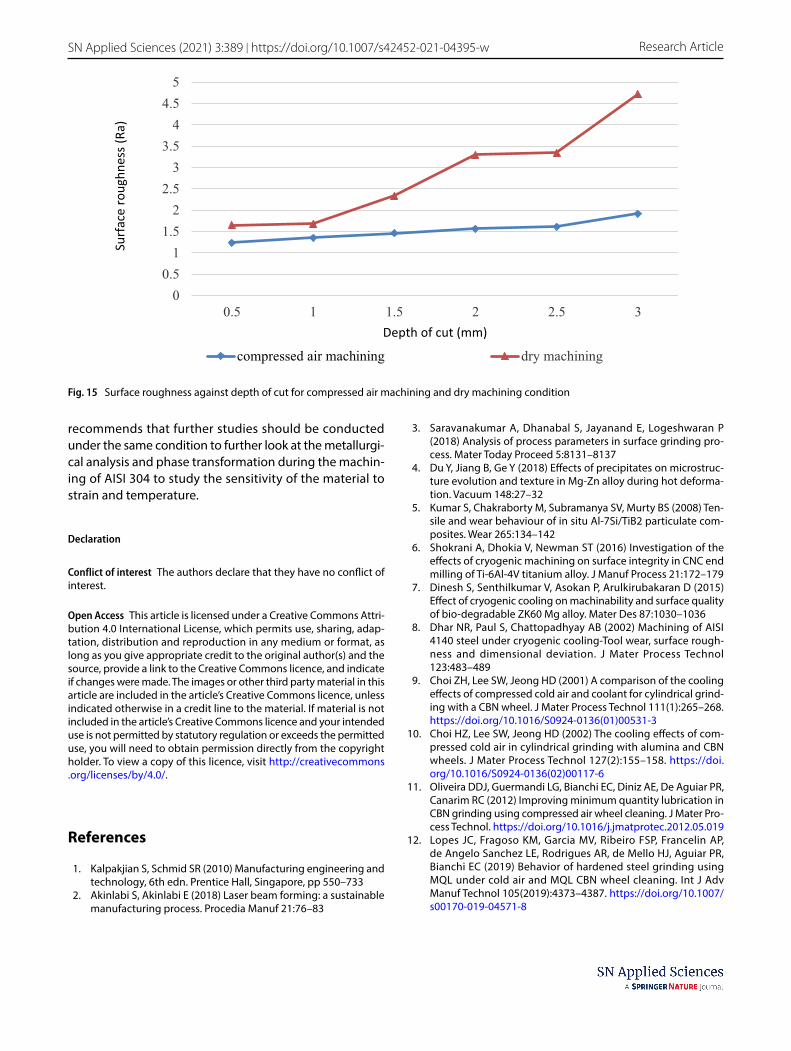
According to the surface roughness test results, the Ra value of both machining conditions increased as the depth of cut increases. However, there were notable influ-ence of the compressed air on the surface roughness of the workpiece as the Ra values of the compressed air machining was almost two times lower compared to dry machining for each of the depth of cut. To further under-stand the relationship between compressed air and sur-face roughness of the workpiece, a line graph was plot-ted. Figure 15 presents the graph of surface roughness against depth of cut for compressed air machining and
dry machining condition. It is evident that the surface roughness increased as the depth of cut increases for both conditions. Furthermore, for the compressed air machin-ing, the increase in surface roughness showed a marginal increment. The reason being that at lower depth of cut, the specific energy was lower as material removal rate was smaller. It is worthy of note that the shape and dimen-sion of the cutting edge penetration depth influenced the grinding forces, surface temperatures, wheel wear and sur-face roughness [22].
4 Conclusion
The study looked at the application of compressed air in grinding operation in comparison with dry machining under the same conditions. The study found that com-pressed air improved the surface integrity of a workpiece by reducing the grinding zone temperature, subsequently minimising the thermal damage on the workpiece. Com-pressed air has a high pressure and good delivery mecha-nism which can reach deeper areas. Therefore, the study has provided empirical evidence that grinding of AISI 304 stainless steel, i.e. grinding in general, is more efficient and effective using compressed air. Therefore, grinding yields better results when conducted using compressed air which facilitates the removal of air barriers around the grinding wheel during the machining process. The presence of compressed air during the machining pro-cess reduced the grinding zone temperature. The surface roughness of the workpiece from compressed air machin-ing was better than workpiece from dry machining. The lower temperature condition reduced the thermal damage of both workpiece and grinding tool. Hence, the grits of the grinding wheel remained sharper with the presence of compressed air which helped produce better surface quality. The higher temperature in dry machining condi-tion increased thermal damage on the grits thus produc-ing higher surface roughness on the workpiece. The study
Table 5 Surface roughness of AISI 304 stainless steel under com-pressed air machining and dry machining condition
Work piece Depth of cut, mm
Surface roughness (Ra), μm
Compressed air machining
Dry machining
A, G 0.5 1.235 1.649B, H 1.0 1.353 1.689C, I 1.5 1.462 2.341D, J 2.0 1.565 3.296E, K 2.5 1.618 3.342F, L 3.0 1.914 4.720
Vol.:(0123456789)
SN Applied Sciences (2021) 3:389 | https://doi.org/10.1007/s42452-021-04395-w Research Article
recommends that further studies should be conducted under the same condition to further look at the metallurgi-cal analysis and phase transformation during the machin-ing of AISI 304 to study the sensitivity of the material to strain and temperature.
Declaration
Conflict of interest The authors declare that they have no conflict of interest.
Open Access This article is licensed under a Creative Commons Attri-bution 4.0 International License, which permits use, sharing, adap-tation, distribution and reproduction in any medium or format, as long as you give appropriate credit to the original author(s) and the source, provide a link to the Creative Commons licence, and indicate if changes were made. The images or other third party material in this article are included in the article’s Creative Commons licence, unless indicated otherwise in a credit line to the material. If material is not included in the article’s Creative Commons licence and your intended use is not permitted by statutory regulation or exceeds the permitted use, you will need to obtain permission directly from the copyright holder. To view a copy of this licence, visit http://creat iveco mmons .org/licen ses/by/4.0/.
References
1. Kalpakjian S, Schmid SR (2010) Manufacturing engineering and technology, 6th edn. Prentice Hall, Singapore, pp 550–733
2. Akinlabi S, Akinlabi E (2018) Laser beam forming: a sustainable manufacturing process. Procedia Manuf 21:76–83
3. Saravanakumar A, Dhanabal S, Jayanand E, Logeshwaran P (2018) Analysis of process parameters in surface grinding pro-cess. Mater Today Proceed 5:8131–8137
4. Du Y, Jiang B, Ge Y (2018) Effects of precipitates on microstruc-ture evolution and texture in Mg-Zn alloy during hot deforma-tion. Vacuum 148:27–32
5. Kumar S, Chakraborty M, Subramanya SV, Murty BS (2008) Ten-sile and wear behaviour of in situ Al-7Si/TiB2 particulate com-posites. Wear 265:134–142
6. Shokrani A, Dhokia V, Newman ST (2016) Investigation of the effects of cryogenic machining on surface integrity in CNC end milling of Ti-6Al-4V titanium alloy. J Manuf Process 21:172–179
7. Dinesh S, Senthilkumar V, Asokan P, Arulkirubakaran D (2015) Effect of cryogenic cooling on machinability and surface quality of bio-degradable ZK60 Mg alloy. Mater Des 87:1030–1036
8. Dhar NR, Paul S, Chattopadhyay AB (2002) Machining of AISI 4140 steel under cryogenic cooling-Tool wear, surface rough-ness and dimensional deviation. J Mater Process Technol 123:483–489
9. Choi ZH, Lee SW, Jeong HD (2001) A comparison of the cooling effects of compressed cold air and coolant for cylindrical grind-ing with a CBN wheel. J Mater Process Technol 111(1):265–268. https ://doi.org/10.1016/S0924 -0136(01)00531 -3
10. Choi HZ, Lee SW, Jeong HD (2002) The cooling effects of com-pressed cold air in cylindrical grinding with alumina and CBN wheels. J Mater Process Technol 127(2):155–158. https ://doi.org/10.1016/S0924 -0136(02)00117 -6
11. Oliveira DDJ, Guermandi LG, Bianchi EC, Diniz AE, De Aguiar PR, Canarim RC (2012) Improving minimum quantity lubrication in CBN grinding using compressed air wheel cleaning. J Mater Pro-cess Technol. https ://doi.org/10.1016/j.jmatp rotec .2012.05.019
12. Lopes JC, Fragoso KM, Garcia MV, Ribeiro FSP, Francelin AP, de Angelo Sanchez LE, Rodrigues AR, de Mello HJ, Aguiar PR, Bianchi EC (2019) Behavior of hardened steel grinding using MQL under cold air and MQL CBN wheel cleaning. Int J Adv Manuf Technol 105(2019):4373–4387. https ://doi.org/10.1007/s0017 0-019-04571 -8
0
0.5
1
1.5
2
2.5
3
3.5
4
4.5
5
0.5 1 1.5 2 2.5 3
Surfa
ce ro
ughn
ess (
Ra)
Depth of cut (mm)
compressed air machining dry machining
Fig. 15 Surface roughness against depth of cut for compressed air machining and dry machining condition

Vol:.(1234567890)
Research Article SN Applied Sciences (2021) 3:389 | https://doi.org/10.1007/s42452-021-04395-w
13. Zong H, Woo S, Do H (2002) The cooling effects of compressed cold air in cylindrical grinding with alumina and CBN wheels. J Mater Process Technol 127(2):155–158
14. Fragoso KM, Francelin AP, Lopes JC, Sanchez LE, de Melo HJ, Lodi AA, Aguiar PR, Bianchi EC (2019) Application of CAMQL tech-nique on external cylindrical grinding of AISI 4340 steel with CBN grinding wheel. Revista Materia. https ://doi.org/10.1590/S1517 -70762 01900 03.0760
15. Saberi A, Rahimi AR, Parsa H, Ashrafijou M, Rabiei F (2016) Improvement of surface grinding process performance of CK45 soft steel by minimum quantity lubrication (MQL) technique using compressed cold air jet from vortex tube. J Clean Prod 131(1):728–738. https ://doi.org/10.1016/j.jclep ro.2016.04.104
16. Rahimi A, Saberi A, Parsa H, Ashrafijou M (2016) Improvement of grinding process performance by minimum quantity lubrica-tion technique using compressed cold air jet from vortex tube. Modares Mech Eng. (MME) 15(10):201–211
17. Nguyen T, Zhang LC (2003) An assessment of the applicabil-ity of cold air and oil mist in surface grinding. J Mater Process Technol 140(1–3):224–230. https ://doi.org/10.1016/S0924 -0136(03)00714 -3
18. Aramcharoen A, Chuan SK (2014) An experimental investigation on cryogenic milling of inconel 718 and its sustainability assess-ment. Procedia CIRP 14:529–534
19. Dogra M, Sharma VS, Dureja JS, Singh GS (2018) Environment-friendly technological advancements to enhance the sustain-ability in surface grinding: a review. J Clea Prod 197:218–231
20. Thangarasu VS, Sivasubramanian R (2012) High speed CNC machining of AISI 304 stainless steel; optimization of process
parameters. Int J Mech Eng Robot Res. https ://doi.org/10.4314/ijest .v4i3.5
21. Zhang J, Li C, Zhang Y, Yang M, Jia D, Liu G, Cao H (2018) Experi-mental assessment of an environmentally friendly grinding process using nanofluid minimum quantity lubrication with cryogenic air. J Clean Prod 193:236–248
22. Matsuo T (1974) The effect of high depth of cut on grinding per-formance of alloy steels. In: Koenigsberger F, Tobias SA (eds) Pro-ceedings of the fourteenth international machine tool design and research conference. Palgrave, London
23. Mekala K, Chandradas J, Chandrasekaran K, Kannan TTM, Ramesh E, Narasing Babu R (2014) Optimization of cylindrical grinding parameters of austenitic stainless steel rods (AISI 316) by Taguchi method. Int J Mech Eng Robot 3(2):208–215
24. de Mello HJ, de Mello DR, Bianchi EC, de Aguiar PR, D’Addona MD (2015) Grinding of AISI 4340 steel with interrupted cut-ting by aluminium oxide grinding wheel. Rem Revista Escola de Minas 68(2):229–238. https ://doi.org/10.1590/0370-44672 01568 0070
25. Das J, Linke B (2016) Effect of manual grinding operations on surface integrity. Procedia CIRP 45:95–98
Publisher’s Note Springer Nature remains neutral with regard to jurisdictional claims in published maps and institutional affiliations.