Embed Size (px)
Citation preview

5
Evaluation of Stress Distribution in Implant-Supported Restoration Under Different Simulated Loads
Paulo Roberto R. Ventura1, Isis Andréa V. P. Poiate1, Edgard Poiate Junior2 and Adalberto Bastos de Vasconcellos1
1Federal Fluminense University, 2Pontifical Catholic University,
Brazil
1. Introduction
Technical and scientific developments, in the form of osseointegrated implants, have
made Restorative Dentistry evolve to become a highly successful form of treatment
(Adell et al., 1981; Binon, 2000), considered as an additional safe tool oral surgeons have
at their disposal to rehabilitate partially and totally edentulous patients. However, many
negative factors can interfere in the treatment, causing clinical and functional
complications that may culminate in the loss of osseointegration (Adell et al., 1981; Jemt
et al., 1989; Naert et al., 2001a, 2001b; Isidor, 2006). The attachment of the crown to the
abutment and of the latter to the implant, the loosening of the fixation screw, and even
its fracture may arise from a poor distribution of occlusal loads in the prosthesis-implant
set (Binon, 1994).
The finite element method (FEM) has been applied to the prognosis of stress distribution in
both the implant and its interface with the adjacent bone, for a comparison not only of
several geometries and applied loads (Hansson, 1999; Bozkaya, Muftu, Muftu, 2004), but
also of different clinical situations (Van Oostewyck et al., 2002) and prosthesis designs
(Papavasiliou et al., 1996). The study of stresses using the FEM is basically a virtual
simulation of two- or three-dimensional mathematical models, in which all biological and
material structures involved can be discretized, that is, subdivided into smaller structures
that preserve individual anatomical and mechanical features.
Considering the physical alterations in components and the peri-implant tissue alterations
to which they are subject under an unbalanced distribution of occlusal loads, it is
fundamental to evaluate the distribution of the stresses generated by functional and
parafunctional masticatory loads on implant-supported restorations to reach a better
understanding of their possible biomechanical etiologic agents. The purpose of this study
was to analyze the stress distribution in single implant-supported restorations, as well as in
the peri-implant bone tissue, by means of a three-dimensional model, using the finite
element method.
www.intechopen.com
Finite Element Analysis – From Biomedical Applications to Industrial Developments 108
2. Material and methods
The finite element method is a technique to solve a complex problem subdividing it into a set of smaller and simpler problems (elements), which can be solved using numerical techniques. In other words, it is a method in which a formulation of equations for each finite element combines elements to get a solution for the whole problem, rather than solving it in just one operation (Holmgren et al., 1998).
To divide the region of interest into elements, it is necessary to generate a mesh. The process to generate the mesh, the elements, their respective nodes, and the boundary conditions is referred to as the problem’s own “discretization” (Geng et al., 2001).
The method of analysis with three-dimensional finite elements (3D FEA) was used. It is composed of three sequential and well-defined phases: pre-processing, processing, and post-processing, all described in detail below.
2.1 Pre-processing
In the pre-processing phase, a mathematical model of the object or structure under study is developed using computer-aided design (CAD). In the generation of the FEM, this geometry is discretized. Next, a physical phase is considered, in which properties equal to those of the materials or structures of the real model they represent are attributed to the elements of the mesh, and some hypotheses are formulated to make the analysis (linear elasticity) viable or just to address the lack of knowledge about the behavior of the material or structure represented (homogeneous and isotropic). Finally, the conditions of model fixation and the characteristics of force (load) are also applied.
2.1.1 The development of a geometric model
A model simulating a single implant-supported prosthesis was developed in the region of the second upper premolar. It is composed of a metallo-ceramic crown on a machined-surface external hexagon implant of regular diameter (Master Screw, Conexão Sistemas de Prótese Ltda – SP, Brasil). The development of this prosthesis model and of the peri-implant support bone was carried out based on the sound tooth model constructed by Poiate (2007). The model was generated with the MSC/PATRAN 2005r2 software and the simulation was carried out with the MSC/NASTRAN 2005r1 software (The MacNeal-Schwendler Corporation - USA). To make the support structures, the anatomical dimensions of the cortical and cancelous bone were based on an image of a vestibulo-lingual cross-section of the upper premolar region presented by Berkovitz, Holland and Moxham (2004). This image was digitized with a high-resolution scanner. The vestibulo-lingual dimensions of the cortical and cancelous bone were taken by the DigXY 1.2 software, developed to digitize bitmap data, largely employed to digitize x,y coordinates from graphs. The model includes the geometries of cortical and cancelous bone, implant, screw, abutment, infrastructure, and of the crown’s ceramic layer.
The dental structure of the original model was removed and models of abutment, fixation screw, and implant were imported, supplied by Conexão Sistemas de Prótese Ltda. The modeling carried out included components equivalent to one external hexagon implant Master Screw of 3.75 mm in diameter and 13 mm in length; one titanium straight abutment
www.intechopen.com

Evaluation of Stress Distribution in Implant-Supported Restoration Under Different Simulated Loads 109
for cemented prosthesis with a 2 mm cervical collar (sectioned at the occlusal end to obtain a final length of 3.55 mm); and one titanium fixation screw with a torque of 20 Ncm.
The implant was installed with the platform cervical boundary coinciding with the boundary of the bone crest, and the axial, mesio-distal, and labio-palatine positions equivalent to the root portion of the original sound tooth. Thus, the prosthetic metallo-ceramic crown could be constructed from a cervical prolongation of the sound tooth crown, also favoring the same spatial positioning.
Fig. 1. Development of the model based on a sound tooth (Poiate, 2007).
The model geometries were used to generate volumetric meshes using the tetrahedral element topology (Tet4), that is, a pyramidal element of four faces with six edges and one node on each edge. Elements with edges of 0.05 mm were used in regions of high curvature, small size, or regions of transition between structures of up to 0.3 mm.
To create the volumetric meshes, it was necessary to proceed from the smaller or most internal structure to the larger or most external, that is, in this case the volumetric mesh was created first in the screw, and then the sequence adopted continued to the extremities, following the procedures in Poiate et al. (2008, 2009a, 2009b, 2011). This procedure assures perfect congruence in the FEM. The degree of discretization in the model derives from studies on the convergence of results and from the capacity of the computer used in the analyses, in order to assure adequate density in the finite element mesh for each model, describing the geometry of different components in a rather realistic way. The discretization detailed above corresponded to the maximum discretization established on a Pentium Core Duo 1.6 MHz computer, with 3.0 GB of RAM and a 160 GB hard disk. Thus, the model discretization generated 164,848 node points and 1,011,727 elements.
2.1.2 Load conditions
The occlusal pattern adopted in this study was the cusp-marginal ridge (one tooth to two teeth), thus justifying the positioning of the simulated occlusal loads. Therefore, four load conditions were applied, with different inclinations and points of application for a total static load of 291.36 N (Ferrario et al., 2004):
a. load distributed among 38 node points, 19 of which on an area of 0.85 mm² of the vestibular cusp, and 19 on an area of 0.75 mm² of the lingual cusp (Kumagai et al., 1999), with an inclination of 45º, but with the resultant (291.36 N) parallel to the tooth long axis, aiming at evaluating the effect of the axial force.
www.intechopen.com

Finite Element Analysis – From Biomedical Applications to Industrial Developments 110
b. oblique load, with an inclination of 45º, distributed among 19 node points on an area of 0.85 mm² of the transverse ridge of the vestibular cusp, aiming at evaluating the vestibular lever effect.
c. load with 0º of inclination distributed among 19 node points on an area of 0.80 mm² of the mesial marginal ridge, aiming at evaluating the proximal lever effect.
d. oblique load, with an inclination of 45º in the vestibular direction, distributed among 19 node points on an area of 0.80 mm² of the mesial marginal ridge, aiming at evaluating the effect of torsion on the long axis.
a) b) c) d)
Fig. 2. a) axial load, b) vestibular lever, c) proximal lever and d) torsion.
2.1.3 Fixation conditions
Contour conditions, also called fixation or bonding conditions, are those determined for the edges or extremities of modeled structures, so that they have some spatial support, with displacement and/or rotation constraint, to allow for the analysis under the applied loads (Bathe, 1996).
For the simulation, the following fixation conditions were applied: in the maxillary sinus, translation restricted to the directions x, y and z, and rotations restricted to the axes x, y and z; at the mesial and distal ends of the cortical and cancelous bone, translation restricted to the direction x and rotations restricted to the axes y and z.
2.1.4 Definition of the mechanical properties of anatomic structures
Mechanical properties were attributed to each element in the discretized model, such as the elastic modulus (E) and the Poisson’s ratio (), considering the particularities of all anatomical structures and materials represented by the elements in the composition of the three-dimensional model. Table 1 shows the values applied to each of these properties, as well as their respective bibliographical references.
Structure/Material Elastic Modulus E
(GPa) Poisson’s Ratio
() Bibliographical Reference
Cortical bone 13.70 0.30 Ko et al. (1992) Cancelous bone 1.37 0.30 Ko et al. (1992)
Ni-Cr 188.00 0.33 Vasconcellos (1999) Titanium (implant,
abutment and screw) 110.00 0.35 Iplikçioglu and Akça (2002)
Feldspathic Ceramic 82.20 0.35 Peyton and Craig (1963)
Table 1. Mechanical properties of structures and bibliographical references.
www.intechopen.com

Evaluation of Stress Distribution in Implant-Supported Restoration Under Different Simulated Loads 111
2.1.5 Formulated hypotheses
As in any type of numerical analysis, some hypotheses needed to be formulated to make modeling and problem solving processes viable. It must be emphasized that the numerical tools available to analyze stresses are much more advanced than the knowledge about the mechanical properties of the structures involved. As in Poiate’s studies (2005, 2006), all constant structures in the model behaved isotropically (mechanical properties did not vary according to the direction), homogeneously (properties were constant independent of location), and were linearly elastic (strains were directly proportional to the force applied), characterized by two material constants, the Elastic Modulus (E) and the Poisson’s Ratio (�), with interfaces between structures presumed to be perfectly bonded. Therefore, the interface implant-bone was considered fully osseointegrated, and the cement layer regarded as negligible, since this study did not intend to analyze stresses on that structure nor its interrelation with the others (Çiftçi, Canay, 2000; Silva, 2005).
2.2 Processing
The software used in the analysis was MSC/NASTRAN (The MacNeal-Schwendler Corporation – USA), version 2005r1, on a Pentium Dual-Core computer, with a 1.7 GHz processor, a 160 Gb hard disk, and 2 Gb of RAM. This software takes information from the previous phase (pre-processing) into account. Based on the contact relationship among mesh elements, it makes a series of mathematical calculations organized in an algorithm, that is, a sequence of instructions logically ordered to solve a problem in a finite number of phases (Silva, 2005). What is mathematically analyzed, in general, is the displacement of element nodes according to the load applied (Holmgren et al., 1998).
2.3 Post-processing
The software MSC/PATRAN 2005r2 employed in the pre-processing was also used in the post-processing to visualize and evaluate results.
2.3.1 Analysis of results
The principal stresses peak values were compared to the values of tensile and compressive strength in the model structures to analyze whether these loads were potentially harmful to the structures.
Structure/Material Tensile Strength
(MPa) Compressive
Strength (MPa) Bibliographical
Reference
Bone 121 167 Tanaka et al. 2003 /
O’Brien, 2005
Cortical Bone - 173 Reilly and Burstein,
1975 Cancelous Bone - 167 Çiftçi and Canay, 2000
Ni-Cr 790 - O’Brien, 2005 Titanium (implant,
abutment and screw) 930 - O’Brien, 2005
Feldspathic Ceramic 37.2 150 O’Brien, 2005
Table 2. Tensile and compressive strength and bibliographical references.
www.intechopen.com

Finite Element Analysis – From Biomedical Applications to Industrial Developments 112
The von Mises criterion, or theory of the maximum distortion energy, was also used in this
study to analyze the results from the implant and its components. It is a rupture criterion to
evaluate ductile materials, based on the determination of the maximum distortion energy of
a structure, that is, of the energy related to changes in form (as opposed to the energy
related to changes in the volume of material) (Beer and Johnston, 1995). The structure failure
occurs when, at any point of the material, the distortion energy per unit of volume is higher
than the yield strength value obtained for the material in a tensile test.
The scale of stresses (which appear in different colors in the figures) does not have equal
intervals. This is a result of the stresses in action on each group of models (different types of
load). Thus, a single scale was defined for all models (except for the axially loaded models)
to make the comparison easier.
3. Results and discussion
3.1 Axial load – Load with resu ltant parallel to the long axis
In Figure 3 (perspective views), compressive stresses can be seen in the region of the
abutment and in the cervical region of the implant, but not intense enough to cause harm
(between 1 and 5 MPa).
Again in Figure 3 (internal views), it can be observed the result of the internal maximum
principal stresses. The concentration of tensile stresses on the region of the central groove of
the occlusal surface (40 to 60 MPa), seen in Figure 4, shows a narrow strip on the external
surface, which indicates a stronger tendency for rupture or formation of small cracks in the
ceramic surface only, since the decreasing gradient of stresses reach a peak value of only 20
MPa on the ceramic close to the infrastructure. These tensile stresses reach the infrastructure
(Ni-Cr), but they are not harmful, given their low intensity, with a peak value of 20 MPa,
well below the tensile strength of the material.
Fig. 3. Perspective and internal views of all structures. Maximum principal stresses in model under longitudinal load.
www.intechopen.com
Evaluation of Stress Distribution in Implant-Supported Restoration Under Different Simulated Loads 113
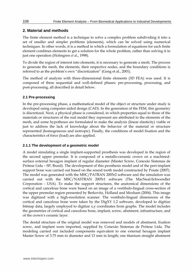
Fig. 4. Occlusal view. Maximum principal stresses in model under longitudinal load.
In Figure 4, it can be observed that the higher compressive stress values are located at points under the area where the load was applied (10 to 55 MPa, well below the tensile strength value of 150 MPa). On the other hand, the increasing tensile stress gradient, between 40 and 60 MPa, concentrated on the region of the central groove, is higher than the tensile strength value (37.2 MPa), suggesting a stronger tendency for micro-cracks in the ceramic.
To compare and discuss the results obtained by Poiate (2007), the stress values found in the cortical and cancelous bone of a sound tooth model are twice lower than the values found in the implant model (between 5 and 10 MPa), in consequence of the absence of periodontal ligament and tooth in the latter.
In Figure 5, very low compressive stresses can be seen in the region of the cortical bone in contact with the implant platform, with a peak value of 8 MPa.
Fig. 5. Perspective view of the cortical bone. Maximum principal stresses in model under longitudinal load. In A, disto-vestibular view; in B, mesio-palatine view.
Figure 6 shows that the concentration of compressive stresses on the region in contact with the implant is on a narrow strip on the external surface of the cortical bone. Next to the cancelous bone, it shows a concentration of tensile stresses of 10 MPa.
www.intechopen.com

Finite Element Analysis – From Biomedical Applications to Industrial Developments 114
Fig. 6. Internal view of the cortical bone. Maximum principal stresses in model under longitudinal load. In A, mesio-distal section; in B, vestibulo-palatine section.
In Figure 7, there is a concentration of bulb-shaped tensile stresses on the cancelous bone in
contact with the implant, with values ranging from 0.5 to 2 MPa approximately. It is also
possible to see that the compressive stresses in contact with the implant thread decrease
towards the implant apex, even though the tensile stresses in contact with the implant
thread are constant (2 to 4 MPa).
Fig. 7. Perspective and internal view of the cancelous bone. Maximum principal stresses in model under longitudinal load.
According to Lehmann and Elias (2008), to minimize this higher concentration of stresses,
new implant forms should be employed, among them platform switching and micro-threads
in the most cervical region of the implant.
The implant and its components withstood the stress and did not reach the tensile strength
of the material (Figure 8). Tensile stresses between 10 and 20 MPa can be seen in the most
cervical region of the implant. The apical third of the implant shows lower tensile stresses
(up to 1 MPa) as a result of its anatomy, with no threads in portions of each quadrant, thus
minimizing stress concentration. Again in Figure 8, there are compressive stresses on the
apex (between 1 and 10 MPa), as well as on the medium third of the implant, a region
corresponding to the screw apex (between 1 and 10 MPa). Low tensile stresses are found in
the region in contact with the apical third of the screw, in the medium third of the implant
(between 10 and 60 MPa), which might result in the loss of stability of the fixation screw.
www.intechopen.com

Evaluation of Stress Distribution in Implant-Supported Restoration Under Different Simulated Loads 115
Fig. 8. Perspective and internal view of the implant. Maximum principal stresses in model under longitudinal load.
According to Dinato (2001), occlusal forces with axial resultant produce a vertical load and do not exert force on the screw nor cause screw loosening. In Figure 9 (perspectives A and B), it can be seen a prevalence of low-intensity tensile stresses on the screw, with higher values concentrated on the apex, on the distal surface (74 MPa). Again in Figure 9 (sections A and B), compressive stresses between 1 and 10 MPa are seen on the coronal third, in the region without spindle. Tensile stresses from 20 to 60 MPa are seen on the screw apex.
Fig. 9. Perspective and internal view of the screw. Maximum principal stresses in model under longitudinal load.
To obtain uniform stress distribution in implants, it is necessary a precise adjustment of the abutment, since the unit closest to the load will be subject to the greatest stresses (Rangert, Jemt and Jörneus, 1989). Contrary to this statement, when under axial load the highest stress values are below the cervical third of the abutment (in contact with the screw, see Figure 10), in the medium third and in the platform of the implant (Figure 8).
www.intechopen.com

Finite Element Analysis – From Biomedical Applications to Industrial Developments 116
Fig. 10. Perspective and internal view of the abutment. Maximum principal stresses in model under longitudinal load.
The results of the longitudinal load revealed that there is a concentration of von Mises
stresses, with a peak value of 80 MPa, on the implant head in contact with the cortical bone
and on the abutment collar in contact with the implant, as well as on the screw apex, with a
peak value of 130 MPa.
3.2 Vestibular lever effect – Load of 45 ˚ on the vestibular cusp
Mastication produces mainly vertical forces, but also transverse forces originating from the
horizontal movement of the jaw and from the inclination of the cusps. These forces are
transferred to the implant through the prosthesis, transforming occlusal forces into bone
stresses (Rangert, Jemt e Jörneus, 1989).
Fig. 11. Perspective and internal view of all structures. Maximum principal stresses in model with a load of 45˚ on the vestibular cusp.
Applying load on the vestibular cusp (Figure 11) produces compression on the vestibular cusp, more concentrated on the region of contact with the cortical bone, which acts as a fulcrum. The tensile stress concentrates and reaches its maximum on the opposite side, the palatine. In Figure 11 (perspective B), tensile stresses between 300 and 740 MPa are seen in the abutment neck, but they are lower than the titanium tensile strength of 930 MPa. When analyzing the ceramic, a concentration of tensile stresses with peak value of 740 MPa can be
www.intechopen.com

Evaluation of Stress Distribution in Implant-Supported Restoration Under Different Simulated Loads 117
seen on the implant and on the abutment (Figure 11, section B). It was observed that stress concentration under the place where the load is applied is punctual and well located. In Figure 11 (section A), there is an accumulation of tensile stresses ranging from 50 to 100 MPa on the screw apex, in the medium third of the implant.
Fig. 12. Occlusal view. Maximum principal stresses in model with a load of 45˚ on the vestibular cusp.
In Figure 12, it can be seen that the highest compressive stress values are under the area of application of a load of approximately 156 MPa, rather higher than the values found in the model under axial load (between 10 and 55 MPa, see Figure 4), higher than the strength value (150 MPa). Also, as it occurred under axial load, the tensile stress values adjacent to the area of load application exceeded its strength value, suggesting the possibility of micro-cracks in the ceramic.
A study by Faulkner et al. (1998) showed, as this one does, that implants loaded with forces that are distant from their axis bear considerable stresses on the bone crest. In Figure 13, there are tensile stresses concentrated in the region of contact with the implant on the palatine surface, with a peak value of 300 MPa, higher than the bone tensile strength, suggesting that there will be a fracture in the cortical bone.
Fig. 13. Perspective view of the cortical bone. Maximum principal stresses in model with a load of 45˚ on the vestibular cusp. In A, disto-vestibular view; in B, mesio-palatine view.
www.intechopen.com

Finite Element Analysis – From Biomedical Applications to Industrial Developments 118
Figure 14 shows that only a narrow strip, close to the implant, exceeds the cortical bone tensile strength. However, the incidence of excess stresses on the cortical bone produces micro-fractures and consequent resorption (Burr et al., 1985; Papavasiliou et al., 1996; Holmgren et al., 1998).
Fig. 14. Internal view of the cortical bone. Maximum principal stresses in model with a load of 45˚ on the vestibular cusp. In A, mesio-distal section; in B, vestibulo-palatine section.
The maximum principal stresses on the cancelous bone are shown in Figure 15.
Fig. 15. Perspective and internal view of the cancelous bone. Maximum principal stresses in model with a load of 45˚ on the vestibular cusp.
Comparing the results from models with axial load and vestibular lever effect, it could be observed that the result from the internal maximum principal stresses on the cancelous bone differs in intensity and in the pattern of stress distribution. There is no concentration of bulb-shaped tensile stresses on the cancelous bone in contact with the implant, as occurred in the previous model. Moreover, the tensile stress peak value in the model with vestibular lever effect is 56.9 times higher. It is also possible to see that the compressive stresses in contact with the implant thread appear only on the vestibular surface, which was already expected, since the load was applied to the vestibular cusp, where the implant is being bent. It can be seen that stresses on the cancelous bone in contact with thread pitches or between them reach high values, especially in the coronal third (between 300 and 740 MPa), exceeding the bone tensile strength (121 MPa, Table 2) and suggesting the formation of micro-fractures and consequent resorption (Papavasiliou et al., 1996; Holmgren et al., 1998; De Tolla et al., 2000).
www.intechopen.com

Evaluation of Stress Distribution in Implant-Supported Restoration Under Different Simulated Loads 119
In Figure 16 (perspective B), there are tensile stresses on the medium and cervical third of
the implant, which was expected, since the load was applied to the vestibular cusp. The
implant is being bent, with a fulcrum in the region close to the cortical bone, where there is a
decreasing dissipation of tensile stresses on the palatine surface. Again in Figure 16 (internal
view), there are tensile stresses on the cervical third of the implant, on the lingual surface,
which was expected as well, since the load was applied to the vestibular cusp, with a peak
value of 300 MPa, rather lower than the tensile strength of the material (930 MPa).
Fig. 16. Perspective and internal view of the implant. Maximum principal stresses in model with a load of 45˚ on the vestibular cusp.
In Figure 17, there is a prevalence of tensile stresses on the cervical third of the screw,
between the beginning of the thread and the head, on the palatine surface, which was
already expected, since the load was applied to the vestibular cusp and the screw was being
bent, with a fulcrum in the cervical region in contact with the implant (above the cortical
bone).
Fig. 17. Perspective and internal view of the screw. Maximum principal stresses in model with a load of 45˚ on the vestibular cusp.
Understanding this pattern of stress distribution in the screw is important to explain the problems and complications encountered, such as screw fractures, as described by Zarb and
www.intechopen.com

Finite Element Analysis – From Biomedical Applications to Industrial Developments 120
Schmitt (1990), although they seem slightly probable when we compare the stress values (150 MPa) with the amount necessary for a rupture (930 MPa).
The results revealed in Figure 18 showed a narrow strip of tensile stresses between 300 and
740 MPa on the external surface of the abutment neck, with dissipation to the palatine and
internal surface, but not exceeding its tensile strength. There are tensile stress values (650
MPa in the abutment collar in contact with the implant) rather higher than those in the
model under longitudinal load (peak value of 80 MPa).
Fig. 18. Perspective and internal view of the abutment. Maximum principal stresses in model with a load of 45˚ on the vestibular cusp.
The results from the distribution of von Mises stresses in the implant and its components
showed that higher stress values are found also in the implant head, when compared with
the axial model.
3.3 Proximal lever effect – Load of 0 ˚ on the mesial marginal ridge
In Figure 19, there are tensile stresses between 150 and 300 MPa on the cortical bone in
contact with the implant. They were already expected, given the direction of the force on the
crown, which pulled the implant neck in this area. It is also possible to see tensile stresses (5
MPa) on the line between the abutment and the ceramic, which could be explained by
compression on materials of different rigidity.
In Figure 19, it can also be seen that the highest compressive stress values are under the
application area of a load ranging from approximately 60 to 120 MPa, slightly lower than the
values found in the model with vestibular lever effect (150 MPa), and below the ceramic
compressive strength (150 MPa, Table 2). It shows the place of load application with a well-
located and punctual stress concentration; however, this stress concentration does not
transfer to the vestibular surface (Figure 19, perspective A) and transfers only slightly to the
palatine surface (Figure 19, perspective B). On the other hand, there are tensile stresses close
to the load application point, with values between 50 and 100 MPa, higher than the ceramic
tensile strength, suggesting a possible formation of micro-cracks.
www.intechopen.com

Evaluation of Stress Distribution in Implant-Supported Restoration Under Different Simulated Loads 121
Fig. 19. Perspective and internal view of all structures. Maximum principal stresses in model with a load of 0˚ on the mesial marginal ridge.
According to Gross (2001), neither axial nor non-axial load generate stress concentration on the implant apex. Under the load that generates the proximal lever effect, these results are confirmed in this study. We could observe that the region of the apex does not concentrate compressive stresses, which are dissipated throughout the apical third of the model (with a peak value of 5 MPa).
However, there is a concentration of tensile stresses on the screw apex, with a peak value of 50 MPa (medium third of implant, Figure 19, section A), and tensile stresses on the distal surface of the implant and on the apical third of the abutment, with values between 50 and 100 MPa. Although the tensile stress values found in the implant and its components are lower than their tensile strength value (Table 2), its presence is important, so that we understand complications, such as screw loss and/or loosening, caused by the micro-movements generated between these two surfaces. Again in Figure 19, it is possible to see a concentration of low-intensity tensile stresses only on the cortical bone, in a mesio-distal section, in the occlusal distal region (5 to 10 MPa).
Fig. 20. Occlusal view. Maximum principal stresses in model with a load of 0˚ on the mesial marginal ridge.
www.intechopen.com
Finite Element Analysis – From Biomedical Applications to Industrial Developments 122
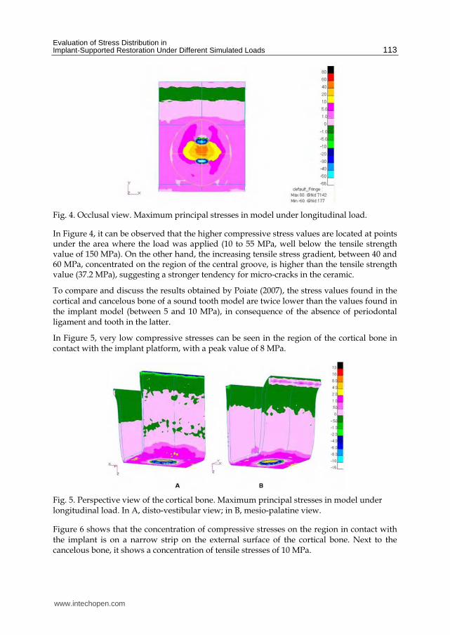
In Figure 21, low-intensity tensile stresses can be seen in the distal cervical region. However, the internal surface of the cortical bone in contact with the implant shows tensile stresses between 50 and 150 MPa, exceeding the bone tensile strength (121 MPa, Table 2), which suggests the formation of micro-fractures and consequent resorption.
Fig. 21. View of the cortical bone. Maximum principal stresses in model with a load of 0˚ on the mesial marginal ridge. In A, disto-vestibular view; in B, mesio-palatine view.
In Figure 22, it is clear the presence of tensile stresses with intensity between 50 and 150 MPa on the cortical bone in contact with the implant, on the distal surface (Figure 22B), exceeding the bone tensile strength (Table 2). In implant-supported restorations, stresses are close to the bone crest (Misch et al., 2001), altering the existing process of bone crest remodeling.
Fig. 22. Internal view of the cortical bone. Maximum principal stresses in model with a load of 0˚ on the mesial marginal ridge. In A, mesio-distal section; in B, vestibulo-palatine section.
In Figure 23, it can be observed that there is a dissipation of low-intensity tensile stresses in the distal cervical region from the cortical to the cancelous bone, as well as a concentration of stresses in contact with the implant. The bone anatomy itself leads to the concentration of local forces, given the existence of an external layer of rigid cortical bone and of an internal
www.intechopen.com

Evaluation of Stress Distribution in Implant-Supported Restoration Under Different Simulated Loads 123
layer of the more elastic cancelous bone. Natural teeth themselves under load generate higher stresses next to the cortical bone (Caputo and Standlee, 1987).
Fig. 23. Perspective and internal view of the cancelous bone. Maximum principal stresses in model with a load of 0˚ on the mesial marginal ridge.
Also in Figure 23, it can be observed that, with a force with inclination of 0º to the axial axis of the set, there was a higher concentration of tensile stresses on the side opposite to the applied force, but with stresses limited to the screw threads of the component, with a peak value of 300 MPa, exceeding the bone tensile strength (121 MPa, Table 2), which suggests the formation of micro-fractures and consequent resorption.
In Figure 24, there is a concentration of tensile stresses only on the cervical third of the implant (with a peak value of 300 MPa). Comparing the models with vestibular and proximal lever effect, it can be considered that the area of tensile stress concentration is larger than in the model that produces a vestibular lever effect, suggesting a stronger possibility of osseointegration failure. The clinical success derived from osseointegration proves that implants resist firmly to the masticatory load; however, the concentration of stresses can result in the loss of osseointegration (Adell et al., 1981).
Again in Figure 24 (internal view), there are tensile stresses located on the cervical third of the implant, on the distal surface, which was expected, since the load was applied to the mesial marginal ridge, with a peak value of 150 MPa, rather lower than the tensile strength of the material (930 MPa) and 50% lower than the peak value of tensile stresses found in the implant of the model that produces a vestibular lever effect.
Fig. 24. Perspective and internal view of the implant. Maximum principal stresses in model with a load of 0˚ on the mesial marginal ridge.
www.intechopen.com

Finite Element Analysis – From Biomedical Applications to Industrial Developments 124
In Figure 25, there is a prevalence of tensile stresses on the cervical third of the screw, between the beginning of the thread and its head or platform, on the distal side, which was already expected, since the load was applied to the mesial marginal ridge and the screw is being bent, with a fulcrum in the cervical region, in contact with the implant (above the cortical bone).
Fig. 25. Perspective and internal view of the screw. Maximum principal stresses in model with a load of 0˚ on the mesial marginal ridge.
Sealing, obtained by the precise adjustment of the abutment surface to the implant, would prevent problems of a peri-implant nature and minimize the development of tangential forces harmful to the interface implant-bone tissue, which could lead to osseointegration failure (Adell et al., 1981). The maximum principal stresses on the abutment are shown in Figure 26.
Fig. 26. Perspective and internal view of the abutment. Maximum principal stresses in model with a load of 0˚ on the mesial marginal ridge.
The results revealed values of von Mises stresses (peak value of 300 MPa in the abutment collar in contact with the implant) lower than those found in the model that produces the vestibular lever effect (peak value of 650 MPa), but higher than those found in the model under longitudinal load (peak value of 80 MPa). Higher values of von Mises stresses are also found in the implant platform, when compared to the axial model.
www.intechopen.com

Evaluation of Stress Distribution in Implant-Supported Restoration Under Different Simulated Loads 125
3.4 Torsion effect – Load of 45 ˚ on the mesial marginal ridge
Single implant-supported restorations can also be subject to rotational or torsion forces, whenever they are clinically demanded through the functional contacts cusp/marginal ridge, that is, in a one tooth to two teeth relation (Cohen et al., 1995).
Figure 27 shows tensile stresses between 50 and 300 MPa on the abutment, which was already expected, in view of the direction of the force on the crown, which pulls the implant in this area. Again in Figure 27 (section B), it can be seen that there is a concentration of tensile stresses on the cervical and medium third of the implant (peak value of 300 MPa) on the palatine surface, lower than the mechanical strength.
In Figure 28, it can be seen that the highest compressive stress values are under the area where the load was applied (10 to 80 MPa, lower than the strength value of 150 MPa), which is a stress concentration point with no transmission to the vestibular surface. However, the existence of tensile stresses close to the application of load (50 to 100 MPa) exceeds the ceramic strength (37.2 MPa) and suggests a localized micro-crack.
Fig. 27. Perspective and internal view of all structures. Maximum principal stresses in model with a load of 45˚ on the mesial marginal ridge.
Fig. 28. Occlusal view of all structures. Maximum principal stresses in model with a load of 45˚ on the mesial marginal ridge.
www.intechopen.com
Finite Element Analysis – From Biomedical Applications to Industrial Developments 126
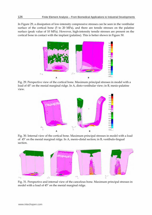
In Figure 29, a dissipation of low-intensity compressive stresses can be seen in the vestibular
surface of the cortical bone (5 to 20 MPa), and there are tensile stresses on the palatine
surface (peak value of 10 MPa). However, high-intensity tensile stresses are present on the
cortical bone in contact with the implant (palatine). This is better shown in Figure 30.
Fig. 29. Perspective view of the cortical bone. Maximum principal stresses in model with a load of 45˚ on the mesial marginal ridge. In A, disto-vestibular view; in B, mesio-palatine view.
Fig. 30. Internal view of the cortical bone. Maximum principal stresses in model with a load of 45˚ on the mesial marginal ridge. In A, mesio-distal section; in B, vestibulo-lingual section.
Fig. 31. Perspective and internal view of the cancelous bone. Maximum principal stresses in model with a load of 45˚ on the mesial marginal ridge.
www.intechopen.com

Evaluation of Stress Distribution in Implant-Supported Restoration Under Different Simulated Loads 127
In Figure 31, there are tensile stresses on the cortical bone (on the palatine surface) in contact with the implant that exceed the tensile strength value and overload the implant. According to Rangert et al. (1995), in a retrospective analysis, this overload induces bone resorption, which seems to precede and contribute to the fracture of implant components.
Also in Figure 31, there are distribution of low-intensity tensile stresses (5 to 10 MPa) and stress concentration on the palatine surface and around the implant.
The concentration of tensile stresses on the cancelous bone in contact with the implant (especially on the threads) reaches the cervical (higher intensity) and medium (lower intensity) thirds on their palatine surface. This was expected, as a result of the direction of the load application. According to Rangert et al. (1989), threads reduce the shear stress on the implant-bone interface when it is under axial load.
Tensile stresses between 50 and 100 MPa (Figure 32) on the implant platform are five times higher than the stresses found in the axial model (10 to 20 MPa). In Figure 32, it can also be observed that there is a concentration of tensile stresses on the medium and cervical third of the implant, as a consequence of load application, in addition to the torsion effect. Moreover, the implant is being bent, with a fulcrum in the region close to the cortical bone, where there is dissipation of decreasing tensile stresses on the palatine surface. Tensile stresses are also seen in the medium and cervical third of the implant, on the distal and lingual surface, a region corresponding to the fulcrum in the cortical bone and to the screw thread (between 50 and 150 MPa). Tensile stresses are found in the region in contact with the apical third of the screw, medium third of the implant. Although the tensile stress value at the end of the screw thread is lower than the mechanical strength of the material, it might contribute to the loss of stability in the fixation screw.
Fig. 32. Perspective view of the implant. Maximum principal stresses in model with a load of 45˚ on the mesial marginal ridge.
In a disto-vestibular view, Figure 33 shows compressive stresses between approximately 5 and 20 MPa, concentrated on the coronal third of the screw, in the region without spindle. Tensile stresses can also be seen in the apex (between 50 and 150 MPa) and in the screw thread (5 to 10 MPa), in a mesio-lingual view, suggesting the possibility of screw loosening in this region. In Figure 33 (sections A and B), there is a prevalence of tensile stresses between 50 and 150 MPa, but concentrated on the medium-coronal third of the screw, a region without thread, and not exceeding the tensile strength of the material.
www.intechopen.com

Finite Element Analysis – From Biomedical Applications to Industrial Developments 128
Fig. 33. Perspective view of the screw. Maximum principal stresses in model with a load of 45˚ on the mesial marginal ridge.
In Figure 34, the prevalence of tensile stresses can be seen on the abutment external surface
(it shows only a narrow strip of low-intensity compressive stresses, of up to 5 MPa, on the
vestibular surface). This prevalence of tensile stresses on the abutment external surface is
important to explain complications such as the loss and/or loosening of screws, since these
stresses are directly related to the abutment-implant interface, as a result of the creation of
micro-movements between the two surfaces when a non-axial load is applied to them.
Fig. 34. Perspective and internal view of the abutment. Maximum principal stresses in model with a load of 45˚ on the mesial marginal ridge.
The result of von Mises stresses revealed tensile stresses values in the abutment collar in
contact with the implant (peak value of 600 MPa) that are higher than those found in the
proximal lever model (peak value of 300 MPa) and close to those found in the model that
produces a vestibular lever effect (peak value of 650 MPa), and considerably higher than
those found in the model under longitudinal load (peak value of 80 MPa).
4. Conclusions
Taking into account that the results produced in this study, for all models, revealed a higher
concentration of forces on the cervical region and higher stress values in the models under
www.intechopen.com

Evaluation of Stress Distribution in Implant-Supported Restoration Under Different Simulated Loads 129
load with a lever effect, no load was able to fracture the components of the implant system
simulated here. However, they may suggest loosening of the screw, micro-cracks in the
ceramic, and bone micro-fractures (resorptions), except for the model under axial load,
which proved to be the least harmful to the stability of the rehabilitating system under
consideration. It can be stated that a careful observation of the criteria for rehabilitation
using implant-supported restorations, as regards the direction of occlusal loads, is crucially
important to achieve success in this therapy.
5. Acknowledgements
This study was partially based on a thesis submitted to The Fluminense Federal
University, in fulfillment of the requirements for the degree of Master of Science. The
authors are grateful to the State of Rio de Janeiro Research Foundation (FAPERJ), the
Conexão Sistemas de Prótese Ltda and to the Finite Element Laboratory in Dentistry
(LEFO), Fluminense Federal University, for their support.
6. References
Adell, R; Lekholm, U; Rockler, B & Brånemark PI. (1981). A 15-year study of
osseointegrated implants in the treatment of edentulous jaw. Int J Oral Surg, Vol.
10, pp. 387-416.
Bathe, KJ. (1996). Finite Elements Procedures (1st ed). Prentice Hall Inc, New Jersey.
Beer, FP; Johnston Jr, ER. (1995). Resistência dos Materiais. Makron Books. São Paulo.
Berkovitz, BKB; Holland, CR & Moxham, BJ. (2004). Anatomia, embriologia e histologia buccal
(3rd ed.). Artmed Editora S.A., Porto Alegre.
Binon, PP. (1994). The role of screws in implant systems. Int J Oral Maxillofac Implants, Vol.9,
pp. 48-63.
Binon, PP. (2000). Implants and components: entering the new millenium. Int J Oral
Maxillofac Implants, Vol. 15, No. 1, pp. 76-94.
Bozkaya, D; Muftu, S & Muftu A. (2004). Evaluation of load transfer characteristics of five
different implants in compact bone at different load levels by finite elements
analysis. J Prosthet Dent, Vol. 92, No. 6, pp. 523-30.
Burr, DB; Martin, RB; Shaffler, B & Radin, E. (1985). Bone remodeling in response to in vivo
fatigue microdamage. J Biomech, Vol. 18, pp. 189-200.
Caputo, AA; Standlee, JP. (1987). Force transmission during function, In: Biomechanics in
Clinical Dentistry, Quintessence, pp. 1-29, Chicago.
Cohen, BI; Pagnillo, M; Condos, S & Deutsch, AS. (1995). Comparison of torsional forces
at failure for seven endodontic post systems. J Prosthet Dent, Vol. 74, No. 4, pp.
350-57.
Çiftçi, Y; Canay, Ş. (2000). The effects of veneering materials on stress distribution in
implant-supported fixed prosthetic restoration. Int J Oral Maxillofac Implants, Vol.
15, No. 4, pp. 5715-82.
Dinato, JC; Polido, WD. (2000). Adaptação passiva: ficção ou realidade? In: Implantes
osseointegrados: cirurgia e prótese, Artes Médicas, pp. 1-283, São Paulo.
www.intechopen.com
Finite Element Analysis – From Biomedical Applications to Industrial Developments 130
De Tolla, DH; Andreana, S; Patra, A; Buhite, R & Comella B. (2000). The role of the finite
element model in dental implants. J Oral Implant, Vol. 24, No. 2, pp. 77-81.
Ferrario, VF; Sforza, C; Serrao, G; Dellavia, C & Tartaglia, GM. (2004). Single tooth bite
forces in healthy young adults. J Oral Rehabil, Vol. 31, No. 1, pp.
Faulkner, G; Wolfaardt, J & Valle, V. (1998).Console abutment loading in craniofacial
osseointegration. Int. J. Oral Maxillofac Implants, Vol. 13, No. 2, pp. 245-52.
Geng, JP; Tan, KB & Liu GR. (2001). Application of finite element analysis in implant
dentistry; A review of the literature. J Prosthet Dent, Vol. 85, No. 6, pp. 585-98.
Gross, MD; Nissan, Samuel R. (2001). Stress distribution around maxillary implants in
anatomic photoelastic models of varying geometry. Part II. J Prosthetic Dent, Vol. 85,
No. 5, pp. 450-454.
Hansson, S. (1999). The implant neck: smooth or provided with retention elements. A
biomechanical approach. Clin Oral Impl Res, Vol. 10, No. 5, pp. 394-405.
Holmgren, EP; Seckinger, RJ; Kilgren, LM & Mante F. (1988). Evaluating parameters of
osseointegrated dental implants using finite element analysis – A two-dimensional
comparative study examining the effects of implant diameter, implant shape, and
load direction. J Oral Implantol, Vol. 24, No. 2, pp. 80-88.
Iplikçioğlu, H; Akça, K. (2002). Comparative evaluation of the effect of diameter, length and
number of implant supporting three-unit fixed partial prostheses on stress
distribution in the bone. J Dent, Vol. 30, No. 1, pp. 41-6.
Isidor F. (2006). Influence of forces on peri-implant bone. Clin Oral Impl Res, Vol. 17, No. 2,
pp. 8-18.
Jemt, T; Lekholm, U & Adell, R. (1989). Osseointegrated implants in the treatment of
partially edentulous patients: a preliminary study on 876 consecutively placed
fixtures. Int J Oral Maxillofac Implants, Vol. 4, pp. 211-217.
Ko, CC; Chu, CS; Chung,,KH & Lee, MC. (1992). Effects of posts on dentin stress distribution
in the bone in pulpless teeth. J Prosthet Dent, Vol. 68, No. 2, pp. 421-27.
Kumagai, H; Suzuki, T; Hamada, T; Sondang, P; Fugitani, M & Nikawa H. (1999). Occlusal
force distribution on the dental arch during various levels of clenching. J Oral
Rehabil, Vol. 26, No. 12, pp. 932-35.
Lehmann, RB; Elias, CN. (2008). Tensões em implantes cônicos com hexágono externo e com
hexágono interno. Rev Dental Press Periodontia Implantol, Vol. 2, pp.
Naert, IE; Duyck, JA; Hosny, MM; Quirynen, M & Van Steenbherg, D. (2001a). Freestanding
in tooth-implants connected prostheses in the treatment of partially edentulous
patients: Part I: an up to 15-years radiographic evaluation. Clin Oral Impl Res, Vol.
12, pp. 237-244.
Naert, IE; Duyck, JA; Hosny, MM; Quirynen, M & Van Steenbherg, D. (2001b). Freestanding
in tooth-implants connected prostheses in the treatment of partially edentulous
patients: Part II: an up to 15-years radiographic evaluation. Clin Oral Impl Res, Vol.
12, pp. 245-251.
O’ Brien, WJ. (April 1996). Biomaterials Properties Database, In: University of Michigan, 25
december 2006. Available from:
http://www.lib.umich.edu/dentlib/Dental_tables/toc.html
www.intechopen.com

Evaluation of Stress Distribution in Implant-Supported Restoration Under Different Simulated Loads 131
Papavasiliou, G; Kamposiora, P; Bayne, SC & Felton, DA. (1996). Three-dimensional finite
element analysis of stress-distribution around single tooth implants as a function of
bony support, prosthesis type, and loading during function. J Prostet Dent, Vol. 76,
No. 6, pp. 633-40.
Peyton, FA; Craig, RG. (1963). Current evaluation of plastics in crow and bridge prostesis. J
Prosthet Dent, Vol. 13, pp. 743-53.
Poiate IAVP. (2005). Análise da distribuição de tensões em modelos tridimensionais de um
incisivo central superior, gerados a partir de tomografia computadorizada, sob
diferentes magnitudes de carga: método dos elementos finitos, In: Universidde
federal Fluminense. Master’s dissertation, Niterói.
Poiate IAVP. (2007). Análise biomecânica de dentes restaurados com retentor intra-radicular
fundido, com e sem ferula, In: Universidade de São Paulo. Doctoral Thesis, São
Paulo.
Poiate, IAVP; Vasconcellos, AB; Andueza, A; Pola, IRV & Poiate Jr, E. (2008). Three
dimensional finite element analyses of oral structures by computerized
tomograghy. J Biosc Bioeng, Vol. 106, No. 6, pp. 906-9.
Poiate, IAVP; Vasconcellos, AB; Santana, RB &, Poiate Jr, E. (2009a). Three-Dimensional
Stress Distribution in the Human Periodontal Ligament in Masticatory,
Parafunctional, and Trauma Loads: Finite Element Analysis. J Periodontology, Vol.
80, pp. 1859-1867.
Poiate, IAVP; Vasconcellos, AB; Poiate Jr, E & Dias KRC. (2009b). Stress distribution in the
cervical region in a 3D FE. Brazilian Oral Research, Vol. 23, pp. 161-168.
Poiate, IAVP; Vasconcellos, AB; Mori, M &, Poiate Jr, E. (2011). 2D and 3D finite element
analysis of central incisor generated by computerized tomography. Comput Methods
Programs Biomed, Vol 104, No. 2, pp. 292-9.
Rangert B, Jemt, T, Jörneus L. Forces and moments on Brånemark Implants. Int J Oral
Maxillofac Implants, 4(3):241-47, 1989.
Reilly, DT; Burstein, AH. (1975). The elastic and ultimate properties of compact bone tissue.
J Biomech, Vol. 8, pp. 393-405.
Silva MG. (2005). Influência da esplintagem de restaurações protéticas fixas e do número de
implantes na distribuição de tensões em mandíbula edentada posterior – análise
em elementos finitos. In: Universidade de São Paulo. Master´s dissertation, São
Paulo.
Tanaka, M; Naito, T & Yokota M. (2003). Finte element analysis of the possible
mechanism of cervical lesion formation by occlusal forces. J Oral Rehabil, Vol. 30,
pp. 60-67.
Van Oostewyck, H; Duyck, J; Vander Sloten, J; Van Der Perri, G & Naert, I. (2002). Peri-
implant bone tissue strains in cases of dehiscence: a finite element study. Clin Oral
Impl Res, Vol. 13, No. 3, pp. 327-33.
Vasconcellos, AB; Mori, M; Andueza, A; Silva EM (1999). Tensões internas em prótese
parcial fixa com dois sistemas de retenção corono-radicular: método dos elementos
finitos. Rev Bras Odontol, Vol. 59, pp. 206-10.
www.intechopen.com

Finite Element Analysis – From Biomedical Applications to Industrial Developments 132
Zarb, GA; Schmitt, A. (1990). The longitudinal clinical effectiveness of osseointegrated
dental implants: Toronto study. Part III: Problems and complications encountered. J
Posthet Dent, Vol. 64, No. 2, pp. 185-94.
www.intechopen.com

Finite Element Analysis - From Biomedical Applications toIndustrial DevelopmentsEdited by Dr. David Moratal
ISBN 978-953-51-0474-2Hard cover, 496 pagesPublisher InTechPublished online 30, March, 2012Published in print edition March, 2012
InTech EuropeUniversity Campus STeP Ri Slavka Krautzeka 83/A 51000 Rijeka, Croatia Phone: +385 (51) 770 447 Fax: +385 (51) 686 166www.intechopen.com
InTech ChinaUnit 405, Office Block, Hotel Equatorial Shanghai No.65, Yan An Road (West), Shanghai, 200040, China
Phone: +86-21-62489820 Fax: +86-21-62489821
Finite Element Analysis represents a numerical technique for finding approximate solutions to partialdifferential equations as well as integral equations, permitting the numerical analysis of complex structuresbased on their material properties. This book presents 20 different chapters in the application of FiniteElements, ranging from Biomedical Engineering to Manufacturing Industry and Industrial Developments. It hasbeen written at a level suitable for use in a graduate course on applications of finite element modelling andanalysis (mechanical, civil and biomedical engineering studies, for instance), without excluding its use byresearchers or professional engineers interested in the field, seeking to gain a deeper understandingconcerning Finite Element Analysis.
How to referenceIn order to correctly reference this scholarly work, feel free to copy and paste the following:
Paulo Roberto R. Ventura, Isis Andréa V. P. Poiate, Edgard Poiate Junior and Adalberto Bastos deVasconcellos (2012). Evaluation of Stress Distribution in Implant-Supported Restoration Under DifferentSimulated Loads, Finite Element Analysis - From Biomedical Applications to Industrial Developments, Dr.David Moratal (Ed.), ISBN: 978-953-51-0474-2, InTech, Available from:http://www.intechopen.com/books/finite-element-analysis-from-biomedical-applications-to-industrial-developments/stress-distribution-in-implant-supported-restorations-under-different-simulated-loads

© 2012 The Author(s). Licensee IntechOpen. This is an open access articledistributed under the terms of the Creative Commons Attribution 3.0License, which permits unrestricted use, distribution, and reproduction inany medium, provided the original work is properly cited.