Embed Size (px)
Citation preview
Evaluation of RAVEN Surgical Telerobot during the NASA Extreme Environment Mission Operations (NEEMO) 12 Mission
Blake HannafordDiana FriedmanHawkeye King
Mitch LumJacob Rosen
Ganesh Sankaranarayananblake<<AT>>ee.washington.edu
Dept of EE, University of WashingtonSeattle WA, 981952500
UWEE Technical Report Number UWWEETR200900026Feb2009
Department of Electrical Engineering University of Washington Box 352500 Seattle, Washington 981952500 PHN: (206) 5432150 FAX: (206) 5433842 URL: http://www.ee.washington.edu
Original Filing Date: December 14, 2007
Overview
The University of Washington’s BioRobotics Laboratory, under the direction of Dr Blake Hannaford, supported the University of Cincinnati’s telesurgery effort during the NEEMO 12 mission conducted May 718, 2007. The UW RAVEN telerobotic system was deployed to the Aquarius Habitat to conduct a variety of research tasks.
The goals of this mission were to advance and demonstrate technologies related to remote healthcare for astronauts on extended space missions. In particular, the capability of surgical intervention by remotely operated surgical robotics. Two surgical robots were deployed into the Aquarius habitat, the UW RAVENand the SRI, International M7 robot. Control of the robots was provided over an Internet link from UW (Seattle, WA) and SRI (Palo Alto, CA), respectively. The last 10 mile connection to the remote site was provided by a microwave link from shore to buoy and a 20m cable down to the habitat. Organization for the remote surgery component of the NEEEMO12 mission is included expertise from Dr. Hannaford, Dr. Jacob Rosen, Mr. Mitch Lum, and Ms Diane Friedman.
Mission PreparationPrior to the mission, UC surgeon Dr. Timothy Broderick, NASA flight surgeon Dr, Joseph
Schmid, and geologist Mary Sue Bell came to the University of Washington for two days of training. They learned and practiced procedures for operation, assembly and disassembly of RAVEN.
In preparation for integration of the RAVEN into the habitat, NASA requirements necessitated creation of extensive operational documentation for the RAVEN’s startup, shutdown, and Estop recovery procedures. RAVEN was shipped to the NURC operational facility on 23April2007. Two UW graduate students, Mitch Lum and Diana Friedman then traveled to NURC and set up RAVEN and verified operation. The RAVEN was then dismantled, packaged and potted down to the Aquarius by U.S. Navy divers. Mr. Lum made a dive down to the habitat to repair some damage to the RAVEN sustained by water pressure applied through the walls of the dive bag.
Drs. Broderick and Schmid reassembled the RAVEN in Aquarius for the teleoperation experiments. (Figure 1) The RAVEN was controlled from three separate locations. Master consoles were set up in Seattle, at the shore base in Key Largo FL, and at Cincinnati Museum Center in Cincinnati, OH. Operators at these locations tested other, nonsurgical performances of the robot including simulated manipulation of moon rocks in a sterile environment. All locations used the Sensable Phantom Omnis as the input devices. (Figure 2). Surgeons performed experimental benchmark tests drawn from the Society of American Gastrointestinal Endoscopic Surgeons (SAGES) Fundamentals of Laparoscopic Surgery (FLS) test protocol (Figure 3).
For surgery tasks in Seattle, two different video systems were used (HaiVision to VLC and iChat V.2.1.3 on Apple Macintosh), as explained below. The HaiVision 1060 (HaiVision Systems
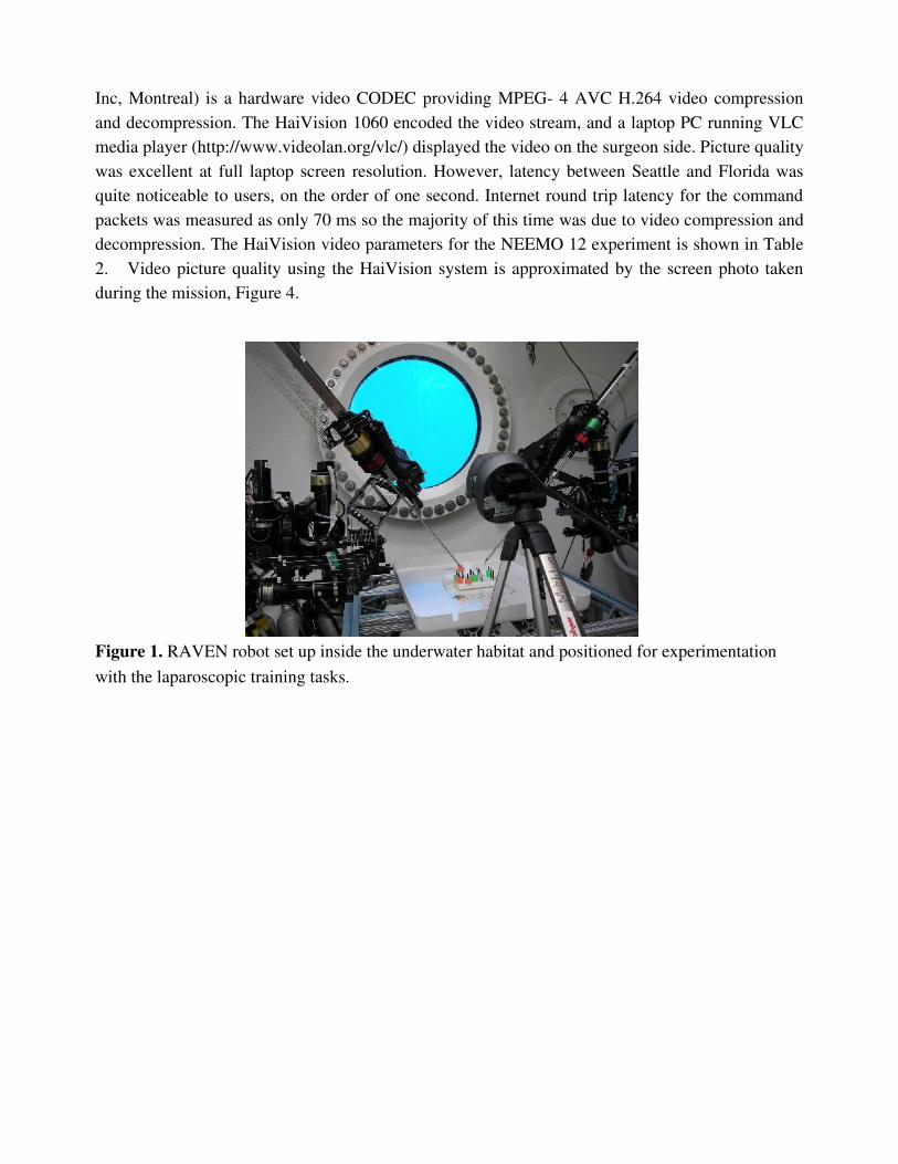
Inc, Montreal) is a hardware video CODEC providing MPEG 4 AVC H.264 video compression and decompression. The HaiVision 1060 encoded the video stream, and a laptop PC running VLC media player (http://www.videolan.org/vlc/) displayed the video on the surgeon side. Picture quality was excellent at full laptop screen resolution. However, latency between Seattle and Florida was quite noticeable to users, on the order of one second. Internet round trip latency for the command packets was measured as only 70 ms so the majority of this time was due to video compression and decompression. The HaiVision video parameters for the NEEMO 12 experiment is shown in Table 2. Video picture quality using the HaiVision system is approximated by the screen photo taken during the mission, Figure 4.
Figure 1. RAVEN robot set up inside the underwater habitat and positioned for experimentation with the laparoscopic training tasks.
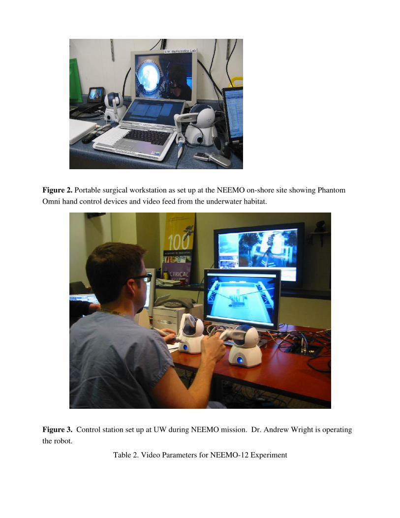
Figure 2. Portable surgical workstation as set up at the NEEMO onshore site showing Phantom Omni hand control devices and video feed from the underwater habitat.
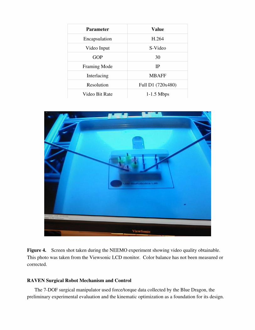
Figure 3. Control station set up at UW during NEEMO mission. Dr. Andrew Wright is operating the robot.
Table 2. Video Parameters for NEEMO12 Experiment
Parameter Value
Encapsulation H.264
Video Input SVideo
GOP 30
Framing Mode IP
Interlacing MBAFF
Resolution Full D1 (720x480)
Video Bit Rate 11.5 Mbps
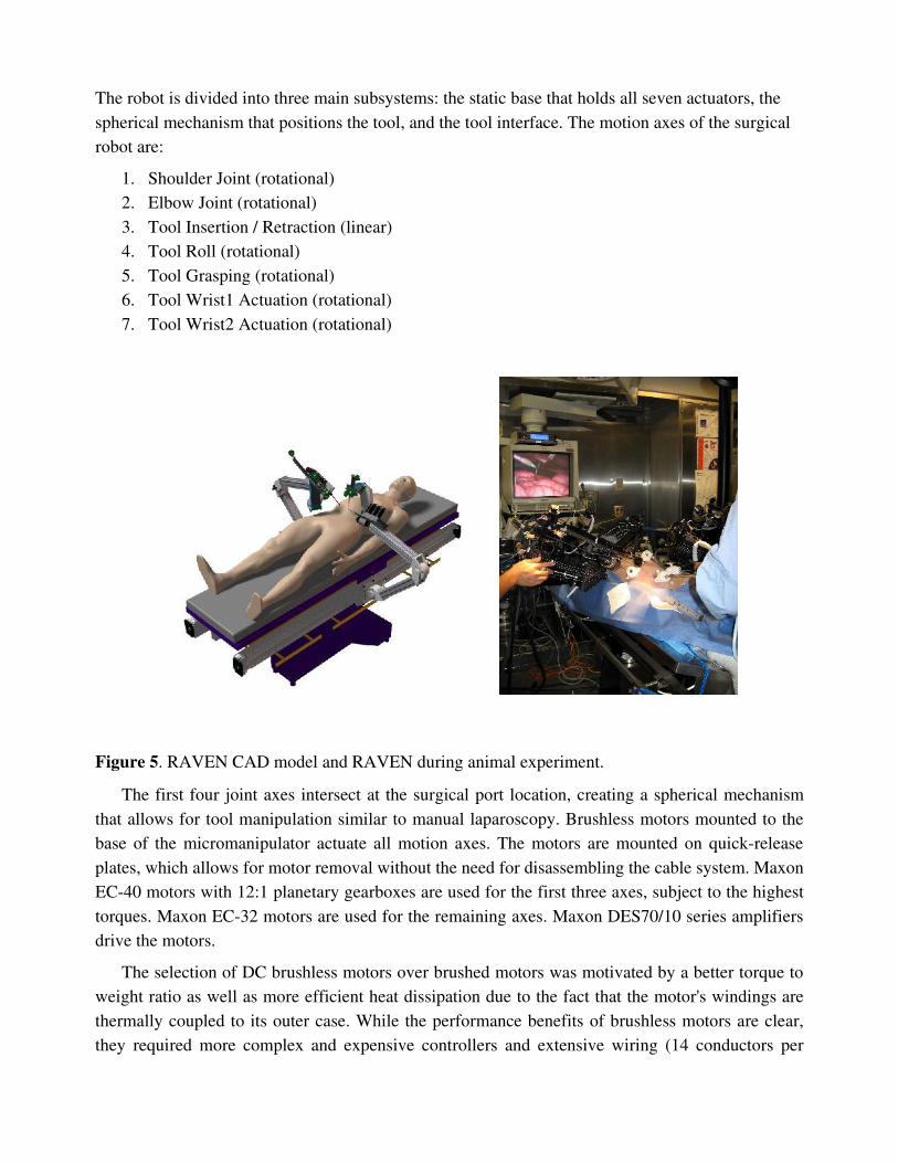
Figure 4. Screen shot taken during the NEEMO experiment showing video quality obtainable. This photo was taken from the Viewsonic LCD monitor. Color balance has not been measured or corrected.
RAVEN Surgical Robot Mechanism and ControlThe 7DOF surgical manipulator used force/torque data collected by the Blue Dragon, the
preliminary experimental evaluation and the kinematic optimization as a foundation for its design.
The robot is divided into three main subsystems: the static base that holds all seven actuators, the spherical mechanism that positions the tool, and the tool interface. The motion axes of the surgical robot are:
1. Shoulder Joint (rotational)2. Elbow Joint (rotational)3. Tool Insertion / Retraction (linear)4. Tool Roll (rotational)5. Tool Grasping (rotational)6. Tool Wrist1 Actuation (rotational)7. Tool Wrist2 Actuation (rotational)
Figure 5. RAVEN CAD model and RAVEN during animal experiment.
The first four joint axes intersect at the surgical port location, creating a spherical mechanism that allows for tool manipulation similar to manual laparoscopy. Brushless motors mounted to the base of the micromanipulator actuate all motion axes. The motors are mounted on quickrelease plates, which allows for motor removal without the need for disassembling the cable system. Maxon EC40 motors with 12:1 planetary gearboxes are used for the first three axes, subject to the highest torques. Maxon EC32 motors are used for the remaining axes. Maxon DES70/10 series amplifiers drive the motors.
The selection of DC brushless motors over brushed motors was motivated by a better torque to weight ratio as well as more efficient heat dissipation due to the fact that the motor's windings are thermally coupled to its outer case. While the performance benefits of brushless motors are clear, they required more complex and expensive controllers and extensive wiring (14 conductors per
motor). The motors of the first three axes have poweroff brakes to prevent tool motion in the event of a power failure.
The cable system is comprised of a capstan on each motor, a pretension adjustment pulley, a pulley array to redirect the cables through the links, and attachment to each motion axis. The shoulder axis is terminated on a single partial pulley. The elbow axis has a dualcapstan reduction stage terminating on a partial pulley; the tool insertion / retraction axis has direct terminations of the cables on the tool holder. The tool rotation, grasping and wrist cables are terminated on capstans on the tool interface box.
Each axis is controlled by two cables, one for motion in each direction, and these two cables are pretensioned against each other. The cables are each terminated at both ends, to prevent any possibility of slipping. The cable system maintains constant pretension on the cables through the entire range of motion; however, there are force and motion couplings between the axes, which must be accommodated for in the control system.
The mechanism's links are machined from aluminum, and are generally Isection shapes with structural covers. These removable covers allow for access to the cable system, while improving torsional stiffness of the links when they are in place. The links are also offset from the joint axis planes, allowing for a tighter minimum closing angle of the elbow joint. Laser pointers attached the shoulder and elbow joints allow for visual alignment of the manipulator relative to the surgical port. When the two dots projected on the skin of the patient converge, the manipulator is positioned such that the center of rotation of the surgical manipulator is aligned with the pivot point on the abdominal wall.
Each surgical manipulator has a mass of approximately 15 kg, which includes the motors, gear heads and brakes.
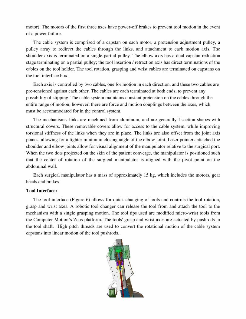
Tool Interface:The tool interface (Figure 6) allows for quick changing of tools and controls the tool rotation,
grasp and wrist axes. A robotic tool changer can release the tool from and attach the tool to the mechanism with a single grasping motion. The tool tips used are modified microwrist tools from the Computer Motion’s Zeus platform. The tools' grasp and wrist axes are actuated by pushrods in the tool shaft. High pitch threads are used to convert the rotational motion of the cable system capstans into linear motion of the tool pushrods.
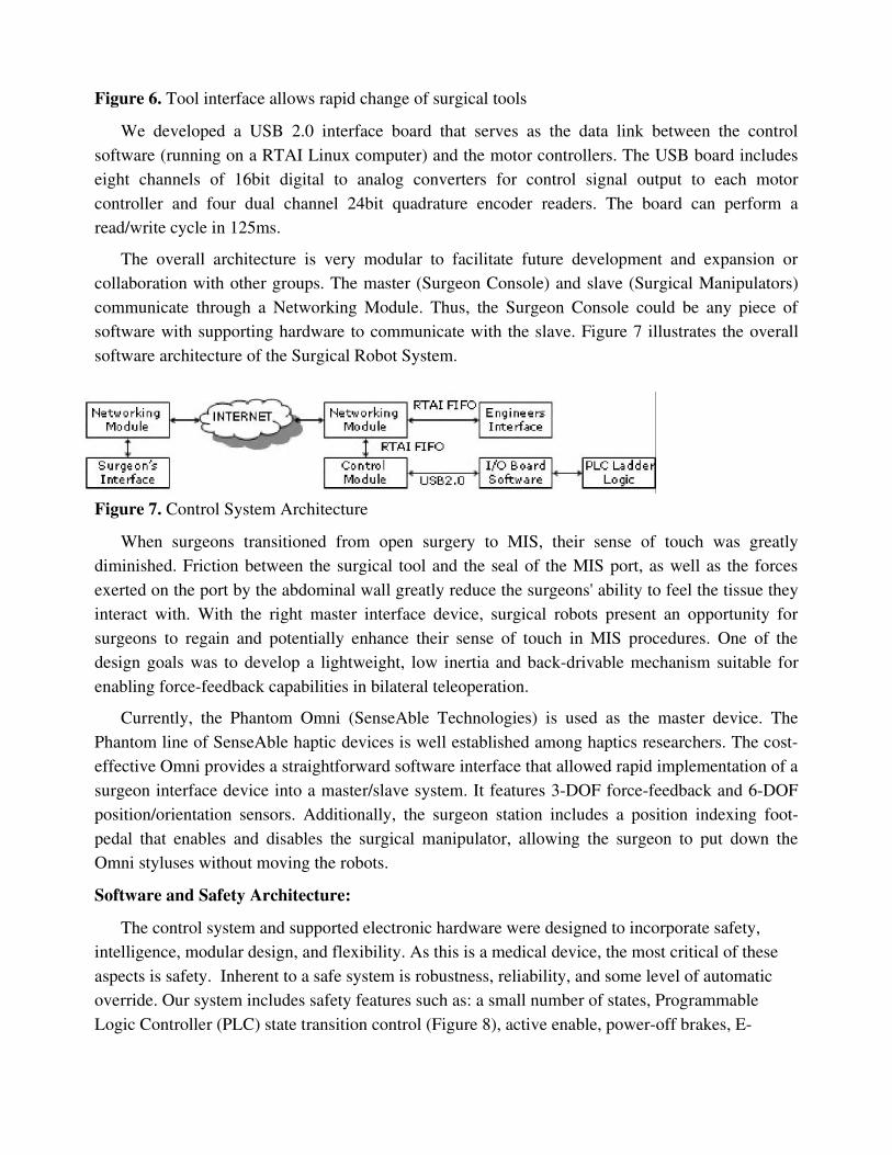
Figure 6. Tool interface allows rapid change of surgical tools
We developed a USB 2.0 interface board that serves as the data link between the control software (running on a RTAI Linux computer) and the motor controllers. The USB board includes eight channels of 16bit digital to analog converters for control signal output to each motor controller and four dual channel 24bit quadrature encoder readers. The board can perform a read/write cycle in 125ms.
The overall architecture is very modular to facilitate future development and expansion or collaboration with other groups. The master (Surgeon Console) and slave (Surgical Manipulators) communicate through a Networking Module. Thus, the Surgeon Console could be any piece of software with supporting hardware to communicate with the slave. Figure 7 illustrates the overall software architecture of the Surgical Robot System.
Figure 7. Control System Architecture
When surgeons transitioned from open surgery to MIS, their sense of touch was greatly diminished. Friction between the surgical tool and the seal of the MIS port, as well as the forces exerted on the port by the abdominal wall greatly reduce the surgeons' ability to feel the tissue they interact with. With the right master interface device, surgical robots present an opportunity for surgeons to regain and potentially enhance their sense of touch in MIS procedures. One of the design goals was to develop a lightweight, low inertia and backdrivable mechanism suitable for enabling forcefeedback capabilities in bilateral teleoperation.
Currently, the Phantom Omni (SenseAble Technologies) is used as the master device. The Phantom line of SenseAble haptic devices is well established among haptics researchers. The costeffective Omni provides a straightforward software interface that allowed rapid implementation of a surgeon interface device into a master/slave system. It features 3DOF forcefeedback and 6DOF position/orientation sensors. Additionally, the surgeon station includes a position indexing footpedal that enables and disables the surgical manipulator, allowing the surgeon to put down the Omni styluses without moving the robots.
Software and Safety Architecture:The control system and supported electronic hardware were designed to incorporate safety,
intelligence, modular design, and flexibility. As this is a medical device, the most critical of these aspects is safety. Inherent to a safe system is robustness, reliability, and some level of automatic override. Our system includes safety features such as: a small number of states, Programmable Logic Controller (PLC) state transition control (Figure 8), active enable, poweroff brakes, E
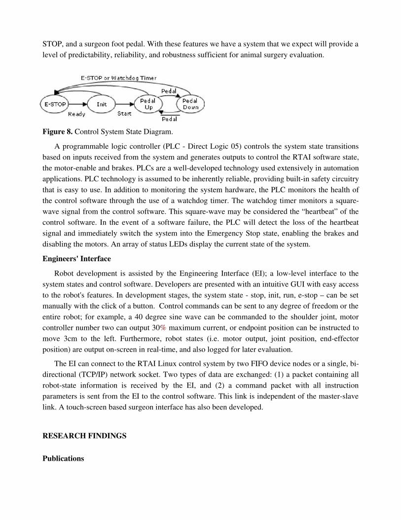
STOP, and a surgeon foot pedal. With these features we have a system that we expect will provide a level of predictability, reliability, and robustness sufficient for animal surgery evaluation.
Figure 8. Control System State Diagram.
A programmable logic controller (PLC Direct Logic 05) controls the system state transitions based on inputs received from the system and generates outputs to control the RTAI software state, the motorenable and brakes. PLCs are a welldeveloped technology used extensively in automation applications. PLC technology is assumed to be inherently reliable, providing builtin safety circuitry that is easy to use. In addition to monitoring the system hardware, the PLC monitors the health of the control software through the use of a watchdog timer. The watchdog timer monitors a squarewave signal from the control software. This squarewave may be considered the “heartbeat” of the control software. In the event of a software failure, the PLC will detect the loss of the heartbeat signal and immediately switch the system into the Emergency Stop state, enabling the brakes and disabling the motors. An array of status LEDs display the current state of the system.
Engineers' InterfaceRobot development is assisted by the Engineering Interface (EI); a lowlevel interface to the
system states and control software. Developers are presented with an intuitive GUI with easy access to the robot's features. In development stages, the system state stop, init, run, estop – can be set manually with the click of a button. Control commands can be sent to any degree of freedom or the entire robot; for example, a 40 degree sine wave can be commanded to the shoulder joint, motor controller number two can output 30% maximum current, or endpoint position can be instructed to move 3cm to the left. Furthermore, robot states (i.e. motor output, joint position, endeffector position) are output onscreen in realtime, and also logged for later evaluation.
The EI can connect to the RTAI Linux control system by two FIFO device nodes or a single, bidirectional (TCP/IP) network socket. Two types of data are exchanged: (1) a packet containing all robotstate information is received by the EI, and (2) a command packet with all instruction parameters is sent from the EI to the control software. This link is independent of the masterslave link. A touchscreen based surgeon interface has also been developed.
RESEARCH FINDINGS
Publications
The following publications describing some of our NEEMO results have been published or will soon appear:
1. Mitchell J.H. Lum, Diana C.W. Friedman, Hawkeye King, Ganesh Sankaranarayanan, Jacob Rosen, Timothy J. Broderick, Mika N. Sinanan, Blake Hannaford, "Raven – A Surgical Robot for Teleoperation", Submitted, American Telemedicine Association Conference, Seattle, April 2006.
2. M. Lum, et al., “Objective Assessment of TeleSurgical Robot Systems: Telerobotic FLS,” InPress, proceedings of MMVR 2008, Long Beach, CA, January 2008.
3. G. Sankaranarayanan, L. Potter, B. Hannaford, 'Measurement and Simulation of Time Varying Packet Delay with Applications to Networked Haptic Virtual Environments,' Proceedings of Robocom 2007, Athens, Greece, October 2007.
4. G. Sankaranarayanan, H. King, S.Y. Ko, M.J.H. Lum, D. Friedman, J. Rosen, B. Hannaford, 'Portable Surgery Master Station for Mobile Robotic Telesurgery', Proceedings of Robocom 2007, Athens, Greece, October 2007.
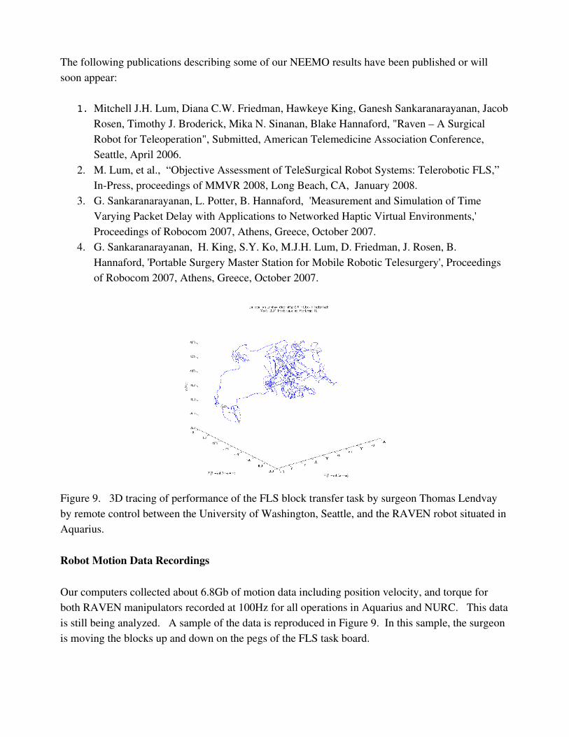
Figure 9. 3D tracing of performance of the FLS block transfer task by surgeon Thomas Lendvay by remote control between the University of Washington, Seattle, and the RAVEN robot situated in Aquarius.
Robot Motion Data Recordings
Our computers collected about 6.8Gb of motion data including position velocity, and torque for both RAVEN manipulators recorded at 100Hz for all operations in Aquarius and NURC. This data is still being analyzed. A sample of the data is reproduced in Figure 9. In this sample, the surgeon is moving the blocks up and down on the pegs of the FLS task board.
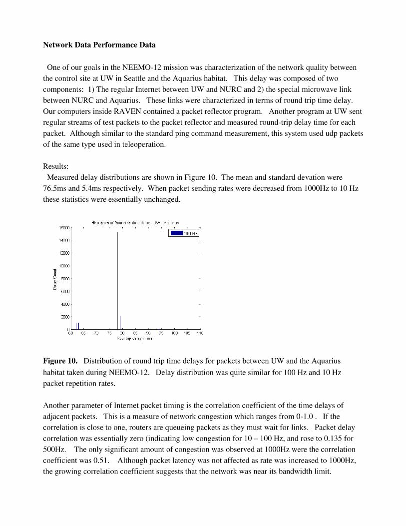
Network Data Performance Data
One of our goals in the NEEMO12 mission was characterization of the network quality between the control site at UW in Seattle and the Aquarius habitat. This delay was composed of two components: 1) The regular Internet between UW and NURC and 2) the special microwave link between NURC and Aquarius. These links were characterized in terms of round trip time delay. Our computers inside RAVEN contained a packet reflector program. Another program at UW sent regular streams of test packets to the packet reflector and measured roundtrip delay time for each packet. Although similar to the standard ping command measurement, this system used udp packets of the same type used in teleoperation.
Results: Measured delay distributions are shown in Figure 10. The mean and standard devation were 76.5ms and 5.4ms respectively. When packet sending rates were decreased from 1000Hz to 10 Hz these statistics were essentially unchanged.
Figure 10. Distribution of round trip time delays for packets between UW and the Aquarius habitat taken during NEEMO12. Delay distribution was quite similar for 100 Hz and 10 Hz packet repetition rates.
Another parameter of Internet packet timing is the correlation coefficient of the time delays of adjacent packets. This is a measure of network congestion which ranges from 01.0 . If the correlation is close to one, routers are queueing packets as they must wait for links. Packet delay correlation was essentially zero (indicating low congestion for 10 – 100 Hz, and rose to 0.135 for 500Hz. The only significant amount of congestion was observed at 1000Hz were the correlation coefficient was 0.51. Although packet latency was not affected as rate was increased to 1000Hz, the growing correlation coefficient suggests that the network was near its bandwidth limit.
Tests from UW to the NURC alone (i.e. not using the microwave link for the last 5 miles) gave a mean delay of 75.2ms and standard deviation of 6.3ms. Thus the microwave link to the Aquarius was highly efficient and not a network bottleneck.
ConclusionThe RAVEN was successfully deployed and demonstrated in the habitat. Surgeons and
researchers were able to operate the robotic arms using the controllers linked across several thousand miles. This included the ATA exhibit in Nashville and the CMC in.


![Kinematic Analysis of the Raven-IITM Research Surgical ... · Kinematic Analysis of the Raven-IITM Research Surgical Robot Platform [REV: 25-Aug-2016] Hawkeye King, Sina Nia Kosari,](https://img.pdfslide.us/doc/110x75/5f0d05ff7e708231d4384c01/kinematic-analysis-of-the-raven-iitm-research-surgical-kinematic-analysis-of.jpg)