Embed Size (px)
Citation preview
Evaluation of Qtronic for Model-Based Testing
M A G N U S A N D E R M O
Master of Science Thesis Stockholm, Sweden 2010
Evaluation of Qtronic for Model-Based Testing
M A G N U S A N D E R M O
Master’s Thesis in Computer Science (30 ECTS credits) at the School of Computer Science and Engineering Royal Institute of Technology year 2010 Supervisor at CSC was Karl Meinke Examiner was Stefan Arnborg TRITA-CSC-E 2010:058 ISRN-KTH/CSC/E--10/058--SE ISSN-1653-5715 Royal Institute of Technology School of Computer Science and Communication KTH CSC SE-100 44 Stockholm, Sweden URL: www.kth.se/csc
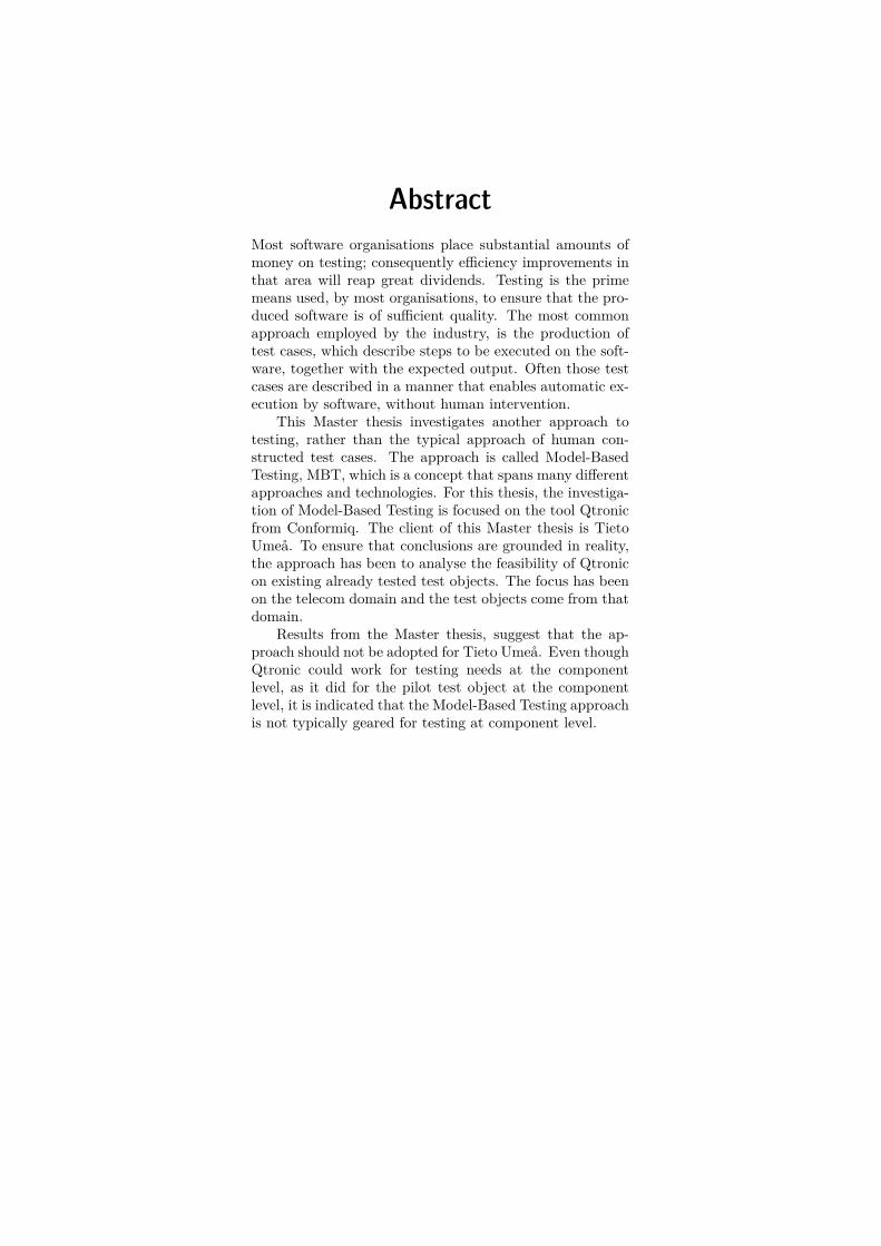
AbstractMost software organisations place substantial amounts ofmoney on testing; consequently efficiency improvements inthat area will reap great dividends. Testing is the primemeans used, by most organisations, to ensure that the pro-duced software is of sufficient quality. The most commonapproach employed by the industry, is the production oftest cases, which describe steps to be executed on the soft-ware, together with the expected output. Often those testcases are described in a manner that enables automatic ex-ecution by software, without human intervention.
This Master thesis investigates another approach totesting, rather than the typical approach of human con-structed test cases. The approach is called Model-BasedTesting, MBT, which is a concept that spans many differentapproaches and technologies. For this thesis, the investiga-tion of Model-Based Testing is focused on the tool Qtronicfrom Conformiq. The client of this Master thesis is TietoUmeå. To ensure that conclusions are grounded in reality,the approach has been to analyse the feasibility of Qtronicon existing already tested test objects. The focus has beenon the telecom domain and the test objects come from thatdomain.
Results from the Master thesis, suggest that the ap-proach should not be adopted for Tieto Umeå. Even thoughQtronic could work for testing needs at the componentlevel, as it did for the pilot test object at the componentlevel, it is indicated that the Model-Based Testing approachis not typically geared for testing at component level.
ReferatUtvärdering av Qtronic för modellbaserad
testning
De flesta mjukvaruprojekt spenderar mycket tid och peng-ar på testning. Förbättringar inom detta område är därförav stort värde. Testning är den mest använda metoden attsäkerställa kvaliteten på programvara. Den vanligaste test-moden inom industrin är att utveckla testfall, som beskriverhur mjukvaran ska exekveras och de förväntade resultaten.Ofta skrivs dessa testfall så att de kan exekveras automa-tiskt.
Detta examensarbete undersöker ett annat tillvägagångs-sätt, i stället för den klassiska metoden att manuellt ut-veckla testfall. Detta tillvägagångssätt kallas Modellbase-rad Testning, MBT, som innefattar många olika angrepps-sätt och teknologier. För detta arbete har undersökning-en begränsats till Modellbaserad Testning med verktygetQtronic från Conformiq. Uppdragsgivaren för detta exa-mensarbete har varit Tieto Umeå. För att slutsatserna skagälla i verkligheten, har denna utredning analyserat hur välQtronic lämpar sig på testobjekt, som redan är testade ochsom är tagna från verksamheten. Fokus är på telekommu-nikationssystem med testobjekt från detta område.
Slutsatsen från detta arbete, indikerar att Modellbase-rad Testning inte borde anammas. Även om Qtronic kanfungera för test på komponentnivå, som det gjorde för mittpilotprojekt, verkar det som att Modellbaserad Testninginte passar för testning på komponentnivå i allmänhet.
PrefaceThis Master Thesis was done at the Umeå office of Tieto. I would like to thank mysupervisor, Per Engman, and my technical supervisor Åke Andersson, both fromTieto. My thanks also go to Staffan Öhman, Lennart Burman and Mikael Strömbergfrom Tieto and Athanasios Karapantelakis and Michael Lidén from Conformiq. Iwould also like to thank my supervisor at KTH, Karl Meinke.
Contents
1 Introduction 31.1 Summary . . . . . . . . . . . . . . . . . . . . . . . . . . . . . . . . . 31.2 Problem . . . . . . . . . . . . . . . . . . . . . . . . . . . . . . . . . . 31.3 Purpose . . . . . . . . . . . . . . . . . . . . . . . . . . . . . . . . . . 4
2 Background about testing methods 52.1 Traditional Testing . . . . . . . . . . . . . . . . . . . . . . . . . . . . 52.2 Testing at Tieto Umeå . . . . . . . . . . . . . . . . . . . . . . . . . . 5
2.2.1 Radio Base Station Integration and Verifiction, RBS I&V . . 62.2.2 Soft I&V . . . . . . . . . . . . . . . . . . . . . . . . . . . . . 62.2.3 Basic test . . . . . . . . . . . . . . . . . . . . . . . . . . . . . 6
2.3 Model-Based Testing . . . . . . . . . . . . . . . . . . . . . . . . . . . 72.3.1 Literature study . . . . . . . . . . . . . . . . . . . . . . . . . 72.3.2 Qtronic . . . . . . . . . . . . . . . . . . . . . . . . . . . . . . 92.3.3 Qtronic MBT example . . . . . . . . . . . . . . . . . . . . . . 102.3.4 The Goat Backend . . . . . . . . . . . . . . . . . . . . . . . . 15
3 Analysis, method description and pilot studies 173.1 Approaches . . . . . . . . . . . . . . . . . . . . . . . . . . . . . . . . 17
3.1.1 The approach chosen . . . . . . . . . . . . . . . . . . . . . . . 173.1.2 Alternative approaches . . . . . . . . . . . . . . . . . . . . . . 17
3.2 Test objects . . . . . . . . . . . . . . . . . . . . . . . . . . . . . . . . 183.2.1 Basic test, AuditController . . . . . . . . . . . . . . . . . . . 183.2.2 Soft I&V . . . . . . . . . . . . . . . . . . . . . . . . . . . . . 25
4 Conclusion 31
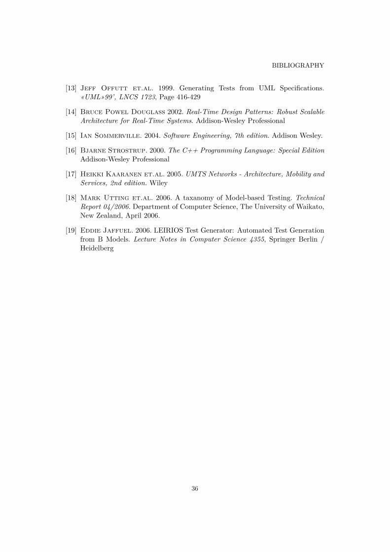
Bibliography 35
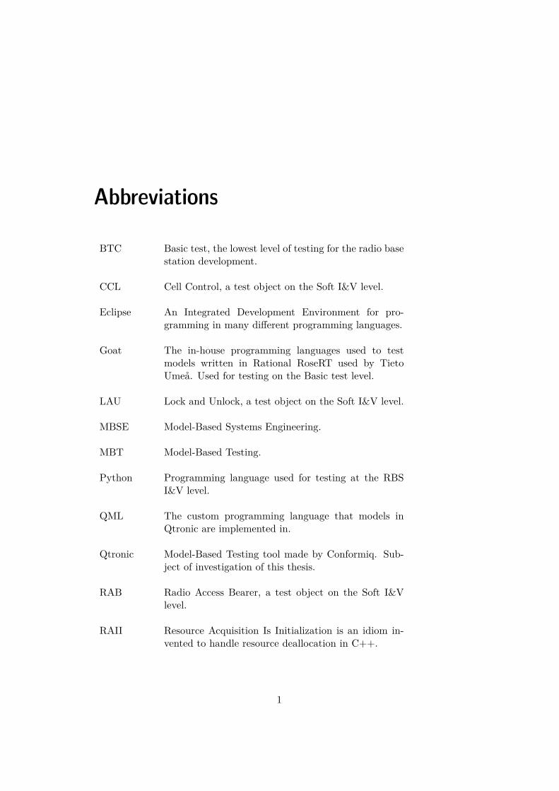
Abbreviations
BTC Basic test, the lowest level of testing for the radio basestation development.
CCL Cell Control, a test object on the Soft I&V level.
Eclipse An Integrated Development Environment for pro-gramming in many different programming languages.
Goat The in-house programming languages used to testmodels written in Rational RoseRT used by TietoUmeå. Used for testing on the Basic test level.
LAU Lock and Unlock, a test object on the Soft I&V level.
MBSE Model-Based Systems Engineering.
MBT Model-Based Testing.
Python Programming language used for testing at the RBSI&V level.
QML The custom programming language that models inQtronic are implemented in.
Qtronic Model-Based Testing tool made by Conformiq. Sub-ject of investigation of this thesis.
RAB Radio Access Bearer, a test object on the Soft I&Vlevel.
RAII Resource Acquisition Is Initialization is an idiom in-vented to handle resource deallocation in C++.
1
ABBREVIATIONS
RationalRoseRT
Rational Rose RealTime is an Integrated Develop-ment Environment. Rational RoseRT supports differ-ent programming languages, apart from its facilitiesfor implementation of state machines in a graphicalnotation. Tieto Umeå uses C++ for the programmingin RoseRT. Before an executable is generated fromthe implementation in RoseRT, RoseRT converts thegraphical constructs and state machines into code ofthe programming language used (in this case C++).
RBS Radio Base Station. The physical entity that handlesthe communication with mobile phones.
RBS I&V Radio Base Station Integration and Verification, refersto testing done of base stations with their full hard-ware.
RNC Radio Network Controller is an entity in a mobile net-work, which multiple base stations are connected to.
Soft I&V Refers to testing done of base stations without theirfull hardware.
Stub A subsystem that is not part of the tested subsystemin the test environment that is replaced with test codeto be able to test the subsystem under test.
SUT System under test.
Test object Same as SUT, system under test.
UML Unified Modeling Language, a standardized modellinglanguage, which can be used to describe the architec-ture and design of software systems.
2
Chapter 1
Introduction
1.1 Summary
The purpose of this Master thesis is to investigate if Tieto Umeå should adoptModel-Based Testing, MBT, for testing of their software. Currently traditional testmethods are used, where test cases are written that exercise a test object fromthe perspective of the users of the test object. Instead, in MBT, a model of thetest object or its environment is designed. Subsequently, test automation software,generates test cases out of the model. For the purpose of this thesis, the programused for this step was Qtronic from Conformiq. Qtronic supports models writtenin their custom language, QML. QML models can consist of textual code as well asa graphical UML Statechart part (optionally). The textual code is in Java inspiredsyntax.
It can be hard to predict upfront if Qtronic is applicable to the intended testingpurposes. My experiences, from making this Master thesis, suggest that it is unwiseto initially invest much in the transition from traditional testing to testing usingQtronic, if it is not known a priori that Qtronic will work for the intended testingpurposes. If it is applicable to take a model-based approach, it could still fail ifthe models, of the test objects, are too complex for Qtronic to be analysed in areasonable time. In the words of Qtronic’s creator ”It follows immediately thatthere exist models that are too difficult for Conformiq Qtronic to handle. Oursolution to this problem is that we do not try to solve it, because to provide thetool’s raison d’être, it is sufficient that there exist enough contexts where ConformiqQtronic can create substantial value.” [10].
1.2 Problem
The software produced at Tieto Umeå, is mainly tested using traditional methodsthrough imperative test scripts. For some of the products, testing is done at multipleabstraction levels. Testing consumes a significant amount of time, in nearly allsoftware projects [12]. The testing is structured as test cases, which collectively
3
CHAPTER 1. INTRODUCTION
exercise some part of the system. The system or a subset of the system that istested is known as the test object. It takes substantial time to create the initial setof test cases. When the system changes and is maintained, the test cases have tobe updated, if they are to provide future value for the organisation. This requiresa lot of resources, since it is during the maintenance phase most resources arespent during the lifetime of a system. Tieto Umeå uses Model-Based SystemsEngineering, MBSE, to model the system and specify requirements. When updatingan existing test object with a new feature, the corresponding test code also needs tobe updated. Often this means that a small set of changes has to be made repeatedlyat many different places in the test code, ranging over many test cases. Keepingthe consistency of the external model, the implementation and the test code isthus troublesome. Therefore testing where the test code is better mapped to therequirements, is sought after.
1.3 PurposeThe intention of this Master thesis is to identify the benefits and discuss the conse-quences if Tieto Umeå decides to switch to Model-Based Testing using Qtronic. Ifsignificant benefits are found that justify the introduction of MBT for testing, thena business plan for the introduction should be made.
4
Chapter 2
Background about testing methods
Testing of a system is made to see if it behaves as expected and to find faults.Testing can be done at multiple levels of abstraction. It is possible to test non-functional requirements, such as performance and usability. However, this reportwill only be concerned with functional requirements.
2.1 Traditional TestingIn traditional test methods, test cases are usually written that exercise a test objectfrom the perspective of the users of the test object.. Testing can be made at multipleabstraction levels.
In component testing the component can be built of other subcomponents. Thetesting is done to find defects (defect testing) and not to verify the correctnessof the component [15]. The component could be a caller of requests, but also becalled by other components as a callee. If the component is the caller (client) ofservices offered by other subsystems and these are not part of the component we aredoing testing on, then we could ”emulate” those subsystems. These subsystems arereplaced by something called a stub. A stub has the same interface as the subsystemit is replacing. However, the logic is simpler and the tester could be required to tellwhat it should respond, depending on the design [2]. The reason to use a stub couldbe that the subsystem is not finished yet or because the subsystem is not trustedyet or because it is easier to exercise the component under test more thoroughly,when the subsystem is replaced with a stub.
2.2 Testing at Tieto UmeåIt was decided that the evaluation should be focused on the base station developmentof Tieto Umeå, because that is their main focus. When looking for test objects, wewere looking for test objects that were good samples from their domain and werenot too big to be hard to model in a limited time frame. Testing of the base stationsis done at multiple abstraction levels; at component level (done by the developers),
5
CHAPTER 2. BACKGROUND ABOUT TESTING METHODS
testing of the complete base station software but without all hardware, and testingof a whole base station with the real hardware. The names of the levels are Basictest, Soft I&V and RBS I&V respectively, see below.
2.2.1 Radio Base Station Integration and Verifiction, RBS I&VRadio Base Station Integration and Verifiction, RBS I&V, is the name of the testing,which is performed with the real hardware. The scripting language used is Python.The testing framework used in the testing, talks with the hardware by sendingelectric signals on the hardware interface. When the base station believes it receivesan electric signal from the antenna, the signal in reality comes from the testingenvironment.
2.2.2 Soft I&VTesting without the hardware is called Soft I&V test. Soft I&V is tested usingthe Erlang programming language and the system is talking with stubs instead ofthe hardware. It is possible from Erlang to control the response from the stubsand verify the messages sent to the hardware. In Soft I&V the system is tested byobserving its hardware interaction and through the outside interface of the SystemUnder Test, SUT, as seen from its real world clients. There is no verification ofinteraction between sub systems inside of the base station, when testing is done atthe Soft I&V level.
2.2.3 Basic testThe developer or the group of developers who developed the SUT does/do compo-nent testing at Tieto Umeå for the Radio Base Station development. Testing atthis level is referred to as Basic test. Testing at the component level is done usingan in-house language called Goat. The implementation of the base station is donein Rational RoseRT with C++.
Former and current ways that Basic test was done
At Tieto Umeå, testing of sub-systems or state machines has been done in differentways in different periods. Initially it was done by selecting a test case that exerciseda component or some components, and then replacing the state machines theycommunicated with with stubs, and then literally implementing the test case inthose stubs in Rational RoseRT. Those stubs are forcing the SUT through the teststeps, where the transitions in the stubs correspond to the test steps in the test cases.Thus, a stub was made up of one sequence of states connected by single transitions.Coding the test cases in that way was quite time-consuming and cumbersome. Apartfrom that, after each change of a test case, the system had to be recompiled (thepart that was affected by the change) and linked. The time for that could be 30minutes and that was considered unacceptable.
6

2.3. MODEL-BASED TESTING
Another approach Tieto Umeå utilized was using a testing tool from Rational(at that time the tool was from Object Time). That tool enabled modelling of testcases as UML Sequence diagrams. Coding the test cases in that format had thesame problems as the previous approach concerning running-, recompilation- andlinking time.
To enable simpler regression testing, the sequence diagrams and the textualoutput that it produced, was parsed and converted into scripts of the scripting lan-guage Goat. This language was invented for that purpose, and then Tieto Umeåimplemented an interpreter for Goat. New testing was done entirely in Goat afterthe conversion and not just for regression purposes. To enable testing using Goat,stubs of the capsules (i.e. state machines that constitute the simulation environ-ment) have to be implemented in Rational RoseRT. Goat has loops, conditionalexpression and arrays. However, real functions with parameters are not part ofthe language. Instead of functions, script files are used, which use global data. Ascript file can be called from another script file. The global data that is read couldbe considered as parameters and the script could be considered as a function. InGoat there exist primitives for sending and receiving messages. For received or sentmessages, the name of the message has to be specified. Values of message can alsobe written directly in the script. It is also possible to declare that some values areirrelevant. When the message is received, Goat will verify the received data againstwhat is written in the script.
2.3 Model-Based Testing
2.3.1 Literature study
Introduction
An objective of this section is to provide a general view of MBT and how it can beused. Another objective is to express the rationale for using MBT and state draw-backs and limitations of MBT, and provide examples of its successful applicationand provide recommendations and best practices about how to use it.
Method
The articles have been found mainly from searching for Model-Based Testing onGoogle and on the search service of the library of the Royal Institute of Technology,KTH, which in turn searches different online article collections such as SpringerLink.I have received some articles from other people working with MBT. Some articleshave been found by perusing the reference section of articles found through theprevious methods.
I have also used a couple of books to find information about software develop-ment and testing.
7
CHAPTER 2. BACKGROUND ABOUT TESTING METHODS
Study
One general definition of MBT is ”... the automatable derivation of concrete testcases from abstract formal models, and their execution” [18]. Commonly the modelis a model of the System Under Test, SUT.
A model in MBT can serve different purposes depending on what MBT techniqueis used. According to Utting et. al. [18], a model in MBT can serve two purposes;”Firstly, it acts as an oracle for the SUT as it encodes the intended behavior.Secondly, its structure can be exploited for the generation of test cases. The modelof the environment is used to restrict the possible inputs to the model.”
A model such as the one used in [8], cannot be used as an oracle and an externaloracle has to be created. However, the model can be used in the generation of testcases. While Qtronic models the SUT and not its environment, it is still possible toinsert assumptions about the environment as assertions. In Qtronic assertions aremodelled using the Qtronic keyword require. In the test object I tested on the unitlevel (see section 3.2.1), it was necessary to put in restrictions on the usage, to limitthe state space explosion and thus the test case generation time. Apart from that acorrect implementation does not need to reject incorrect usage. However, a modelthat accepts incorrect usage is still a correct oracle. Therefore, generated test casescan be examples of wrong usages. If the SUT does not accept those unspecifiedincorrect usages, then the test case will fail. This implies that some aspects of amodel sometimes have to be more complex than the SUT.
[7] claims that the experience of using MBT is still limited and 78 articles aboutMBT are surveyed and among those articles only 8% evaluate MBT experimentally.The application of MBT to real-time systems has not reached maturity and is thetopic of intense research [11].
Further more, doing research on testing is not non-problematic. Testing notdone by the developers is done on a higher level and not typically on the unit level.However, the research that has been done has typically been done on the unit level[13]. Both MBT and traditional testing done by non-developers (dedicated testers),have mostly been done at higher integration levels. Of the 78 articles surveyed in[7], 66% was applied to system testing and just 10% was applied to the unit level.On Qtronic’s homepage, www.conformiq.com, not much is found about the mostappropriate level for testing using Qtronic. However, in an article, [10], written byone of Qtronic’s creators, it is indicated that Qtronic also fits best on higher-levelaspects; ”we have found that successful deployments of model-based testing usuallyfocus on the ’higher level’ issues.”
There are some examples of successful application of MBT. [8] presents two ex-periments where they use the MBT tool GOTCHA-TCBeans to test both a partof the POSIX standard and to test the ”type map generator component” of a Javavirtual machine. The type map generator component is a component that is used tocompute a data structure that can be used to determine if values on the Java stackare references or primitive values. This information is used during garbage collec-tion. The problem is complicated due to Java’s support for exceptions. Therefore,
8
2.3. MODEL-BASED TESTING
they modelled Java’s exception functionality. During the Model-Based Testing ofthe component, they did not use the oracle facilities of GOTCHA-TCBeans. In-stead, they instrumented the Java virtual machine to perform verification that itstype maps were correct. In essence, they modelled the environment instead of theSUT and they modelled the exception functionality rather than the type map gen-erator component, which is the subject of the testing. Some more examples ofsuccessful application are given in a report from IBM Research [9], where they havedeveloped a MBT tool and approach. The projects they have tested it on, includesan Internet telephony application, an Internet API, features of a POSIX compliantfile system and a Call Center API. They also include a non-successful deploymentto another Internet API. However, they attribute that failure to a lack of resources,where the single tester responsible for the deployment had to divide his focus withother projects as well. The article has a high-level focus and it is hard to get a moreconcrete understanding about both the examples and the details of the method-ology and the tool. The drawbacks they identify are only related to the initialcosts of changing the testing method and the drawbacks are not directly related tothe method in itself. According to [19] ”major smart card manufacturers such asGemalto and Giesecke & Devrient, are regularly deploying model-based testing intheir validation processes”.
2.3.2 QtronicModels are implemented in Qtronic, by making statecharts in a program includedwith Qtronic and/or with code written in a tool specific language, QML, similarto Java. The model implemented in Qtronic should be a model of the system thatshould be tested. The modelling language facilitates message passing for modellingthe communication with the outside world. For normal testing, one sends messagesor makes function calls and the SUT receives them. In Qtronic and most MBTapproaches in general, messages that can be received by the SUT will be modelledas something that the model can receive. Similarly, for output, things that the SUTcan send will be something that the model also can send.
What does Qtronic do with the model
From a QML model, Qtronic can generate a set of test cases. A test case will bemade up of a sequence of messages (both outgoing and incoming). ”A valid testcase is a series of inputs and outputs that could be produced by simulating themodel ... ” [6].
Backend
You can define records in QML and messages sent and received in a QML modelare always records. Each QML model defines the ports where the records can bereceived or sent and specifies for each port the records that are allowed. Records aremuch like structs in C++, possibly type parameterized (like C++ templates). A
9
CHAPTER 2. BACKGROUND ABOUT TESTING METHODS
record can hold other records, strings or other fundamental data types (int, double...).
Obviously, a sequence of incoming and outgoing messages in Qtronic must betranslated into a format that the test environment can understand. It is the respon-sibility of the Backend to do this. The Backend takes the test cases and convertsthem into test scripts. Since different clients of Qtronic have different needs and usedifferent scripting languages, Conformiq has provided the possibility for the clientsto implement their own Backends.
2.3.3 Qtronic MBT example
The example test object
To illustrate how Qtronic works, I have made a small example test object. The testobject can receive binary bits. Each time it receives a bit, it tells if it has receivedan odd or even number of bits with the value one so far.
The test object for this example is implemented in Rational RoseRT, as all testobjects on the Basic test level, see section 2.2.3.
Assume the data structure describing a bit is a C++ struct called Bit:
struct Bit {bool b;
};
In Rational RoseRT, messages are referred to as signals. They are sent on portsand each signal has a name. Each signal can have data attached to it. The exampleprogram receives the bits from the signal called inBit on the port called inPort.The C++ struct, named Bit, is carrying the bit information and is attached to thesignal inBit. Notifications, if it has received an odd or even number of bits withthe value one, are sent as the signal oddOrEven on the port called outPort and theC++ struct Bit is attached to the signal and carries the information if it is odd oreven. The value true in the Bit struct in the signal oddOrEven, denotes that anodd number of bits with the value one has been received so far and false denotesthat an even number of bits with the value one has been received so far.
Traditional testing of the test object
Goat is used to test at the Basic test level. The typical way the testing is structuredfor the Basic test level, is to put scripts for the communication in one folder calledsig and put the test cases in a folder called BTC. BTC is an acronym for Basic test,see section 2.2.3. In our case, we create two files in the sig folder, one for the inBitsignal and one for oddOrEven. The implementation looks like the following.
# The inBit.gti file# Set the variable $nextBit before you call this filesend inPort inBit {Bit {b $nextBit}}
10
2.3. MODEL-BASED TESTING
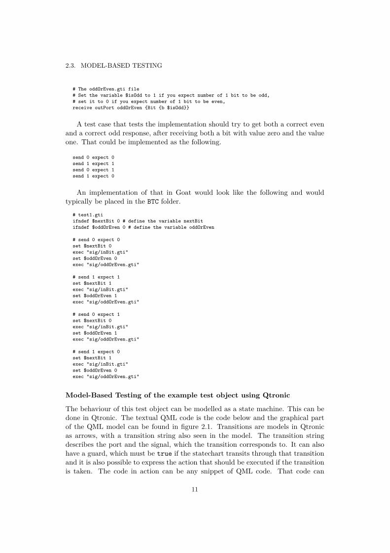
# The oddOrEven.gti file# Set the variable $isOdd to 1 if you expect number of 1 bit to be odd,# set it to 0 if you expect number of 1 bit to be even,receive outPort oddOrEven {Bit {b $isOdd}}
A test case that tests the implementation should try to get both a correct evenand a correct odd response, after receiving both a bit with value zero and the valueone. That could be implemented as the following.
send 0 expect 0send 1 expect 1send 0 expect 1send 1 expect 0
An implementation of that in Goat would look like the following and wouldtypically be placed in the BTC folder.
# test1.gtiifndef $nextBit 0 # define the variable nextBitifndef $oddOrEven 0 # define the variable oddOrEven
# send 0 expect 0set $nextBit 0exec "sig/inBit.gti"set $oddOrEven 0exec "sig/oddOrEven.gti"
# send 1 expect 1set $nextBit 1exec "sig/inBit.gti"set $oddOrEven 1exec "sig/oddOrEven.gti"
# send 0 expect 1set $nextBit 0exec "sig/inBit.gti"set $oddOrEven 1exec "sig/oddOrEven.gti"
# send 1 expect 0set $nextBit 1exec "sig/inBit.gti"set $oddOrEven 0exec "sig/oddOrEven.gti"
Model-Based Testing of the example test object using Qtronic
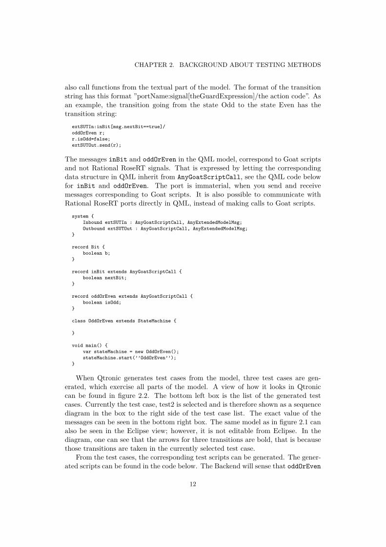
The behaviour of this test object can be modelled as a state machine. This can bedone in Qtronic. The textual QML code is the code below and the graphical partof the QML model can be found in figure 2.1. Transitions are models in Qtronicas arrows, with a transition string also seen in the model. The transition stringdescribes the port and the signal, which the transition corresponds to. It can alsohave a guard, which must be true if the statechart transits through that transitionand it is also possible to express the action that should be executed if the transitionis taken. The code in action can be any snippet of QML code. That code can
11
CHAPTER 2. BACKGROUND ABOUT TESTING METHODS
also call functions from the textual part of the model. The format of the transitionstring has this format ”portName:signal[theGuardExpression]/the action code”. Asan example, the transition going from the state Odd to the state Even has thetransition string:
extSUTIn:inBit[msg.nextBit==true]/oddOrEven r;r.isOdd=false;extSUTOut.send(r);
The messages inBit and oddOrEven in the QML model, correspond to Goat scriptsand not Rational RoseRT signals. That is expressed by letting the correspondingdata structure in QML inherit from AnyGoatScriptCall, see the QML code belowfor inBit and oddOrEven. The port is immaterial, when you send and receivemessages corresponding to Goat scripts. It is also possible to communicate withRational RoseRT ports directly in QML, instead of making calls to Goat scripts.
system {Inbound extSUTIn : AnyGoatScriptCall, AnyExtendedModelMsg;Outbound extSUTOut : AnyGoatScriptCall, AnyExtendedModelMsg;
}
record Bit {boolean b;
}
record inBit extends AnyGoatScriptCall {boolean nextBit;
}
record oddOrEven extends AnyGoatScriptCall {boolean isOdd;
}
class OddOrEven extends StateMachine {
}
void main() {var stateMachine = new OddOrEven();stateMachine.start(’’OddOrEven’’);
}
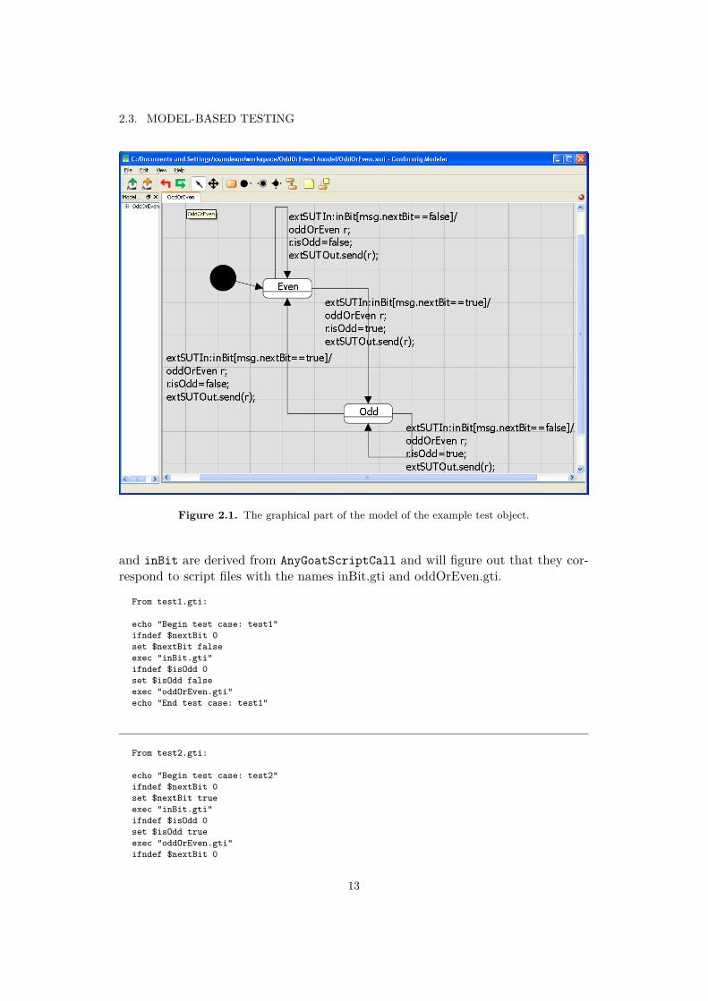
When Qtronic generates test cases from the model, three test cases are gen-erated, which exercise all parts of the model. A view of how it looks in Qtroniccan be found in figure 2.2. The bottom left box is the list of the generated testcases. Currently the test case, test2 is selected and is therefore shown as a sequencediagram in the box to the right side of the test case list. The exact value of themessages can be seen in the bottom right box. The same model as in figure 2.1 canalso be seen in the Eclipse view; however, it is not editable from Eclipse. In thediagram, one can see that the arrows for three transitions are bold, that is becausethose transitions are taken in the currently selected test case.
From the test cases, the corresponding test scripts can be generated. The gener-ated scripts can be found in the code below. The Backend will sense that oddOrEven
12
2.3. MODEL-BASED TESTING
Figure 2.1. The graphical part of the model of the example test object.
and inBit are derived from AnyGoatScriptCall and will figure out that they cor-respond to script files with the names inBit.gti and oddOrEven.gti.
From test1.gti:
echo "Begin test case: test1"ifndef $nextBit 0set $nextBit falseexec "inBit.gti"ifndef $isOdd 0set $isOdd falseexec "oddOrEven.gti"echo "End test case: test1"
From test2.gti:
echo "Begin test case: test2"ifndef $nextBit 0set $nextBit trueexec "inBit.gti"ifndef $isOdd 0set $isOdd trueexec "oddOrEven.gti"ifndef $nextBit 0
13
CHAPTER 2. BACKGROUND ABOUT TESTING METHODS
Figure 2.2. How the model is seen in Eclipse.
set $nextBit falseexec "inBit.gti"ifndef $isOdd 0set $isOdd trueexec "oddOrEven.gti"echo "End test case: test2"
From test3.gti:
echo "Begin test case: test3"ifndef $nextBit 0set $nextBit trueexec "inBit.gti"ifndef $isOdd 0set $isOdd trueexec "oddOrEven.gti"ifndef $nextBit 0
14
2.3. MODEL-BASED TESTING
set $nextBit trueexec "inBit.gti"ifndef $isOdd 0set $isOdd falseexec "oddOrEven.gti"echo "End test case: test3"
2.3.4 The Goat BackendOne requirement of the test objects is that they should be deterministic. Thismeans that given the input it should be possible to predict the exact output. Somenon-deterministic aspects of an implementation can be transformed to a determin-istic model. For example, sometimes when a SUT receives a request it will respondand include some number in the response that will vary from time to time andconsequently it is not deterministic. However, the test system can store the re-ceived value, which can be used later in other messages to be sent to the SUT. Inthis way, it works like a deterministic system. In Goat it is possible to save thevalue from something you received by writing ?$ in front of the variable name, forexample receive port sig {SomeStruct {aField ?$whereToSaveIt}}. I haveimplemented a Backend and QML library that can be used to model those things inQtronic for the Basic Test environment, in the following way. When there is a fieldin a message, that one sometimes does not know the value of, one can declare as aplaceholder in QML. Thus even if the value of the field is not known, the placeholderin the model will be deterministic. The details of that are described in the nextparagraph.
A field in QML of type PlaceHoldableValue<T> can act as a symbol for afield of type T in the SUT. When sending a message in the model and the exactvalue is unknown, then the value can be given a symbolic name. This is doneby assigning the field the result of placeholder<T>("?theSymbolicName"). Ifvalue that the SUT sends is irrelevant, then the field can be can assigned the re-sult of goatNull<T>(). When a message is received and a field of that messageshould be equal to the symbol, then it should be ensured that the field is equal toplaceholder<T>("theSymbolicName"). If the value is known, then the result ofwrapInPlaceHolder<T>(theExactValue) can be used instead.
15

Chapter 3
Analysis, method description and pilotstudies
3.1 ApproachesThe objective of this Master thesis is to research the applicability of Model-BasedTesting using Qtronic for testing at Tieto Umeå. Different approaches for theevaluation are possible.
3.1.1 The approach chosen
We limited the investigation to testing already done for the Radio Base Station.Testing is done at multiple abstraction levels; therefore, it could be worth switchingto Qtronic for testing one level and not the other, due to the differences in goals andmethods of testing for the different abstraction levels. For this reason, the approachchosen is to evaluate Qtronic, on test objects that have already been tested withconventional methods, and then compare them.
3.1.2 Alternative approaches
An alternative approach could be to construct a test object, whose only purposeis to serve as a test object for the comparison. The problem with that approachis that even if Qtronic works well for that test object, there could be some minordifferences that make Qtronic non-suitable for the real test objects. That approachis not uncommon for evaluating other Model-Based Testing methods. [7] surveysdifferent Model-Based Testing articles and from them it is concluded ”Most of theidentified MBT approaches had not been evaluated experimentally”.
How the approach guided our decisions
The evaluation of RBS I&V was turned down; because it is more complex and webelieved it had more prospects for problems with configuration and setup of the
17
CHAPTER 3. ANALYSIS, METHOD DESCRIPTION AND PILOT STUDIES
testing environment.The analysis of Model-Based Testing began with the Basic Test environment.
It is at a lower abstraction level than Soft I&V, going from the concrete to theabstract and this was seen as a good idea. We chose to analyse a test object thatwas already tested, called the AuditController, as it is of adequate complexity andit had one responsibility. A well designed system has cohesive components withideally one responsibility each that are loosely coupled to each other [3].
3.2 Test objects
3.2.1 Basic test, AuditController
Explanation of the test object
The test object is composed of two state machines and is part of a radio basestation, RBS. The names of the state machines are AuditController and Capacity-CreditHandler. A radio base station is connected to a number of cell phones. Anumber of radio base stations are connected to one entity called the Radio NetworkController, RNC [17].
The RNC needs to know the hardware resources that are free to be used forsetting up new calls and other information that is vital. The RNC can query theRBS for that information, such a query is called an audit request and the responseis called the audit response. Such a query will be forwarded to the AuditController.The AuditController asks different subsystems on lower levels for information oftheir capacities.
One of the subsystems is not queried directly because of performance and ar-chitectural reasons; the part that mediates between them is the CapacityCred-itHandler. To get an idea of the rationale behind the CapacityCreditHandler fur-ther insight into the base station hardware is required. A local cell represents akind of physical resource at the base station that the RNC cannot use yet. What acell actually is, is not important for the scope of this thesis and will therefore not beexplained in further detail. A local cell is assigned an id, called localCellId, chosenby the base station. To use a local cell the RNC sets up a cell that corresponds tothat local cell. Thus the cell knows the localCellId for the local cell that it corre-sponds to. It also has an id, assigned by the RNC, called cellId. The RNC cannothave two base stations that have the same cell id for some cells. Obviously for abase station there are at least as many local cells as cells. A base station can consistof different hardware components. Due to physical reasons, a local cell could corre-spond to a hardware resource at one hardware component, while another local cellcould correspond to a hardware resource at some other hardware component. Thisconcept is known as base band pools, or localCellGroups. Cells on the same hard-ware component thus lie on the same base band pool. It is possible to observe thisby checking the localCells’ localCellGroupId. The CapacityCreditHandler listensfor changes in the base band pools and saves them. If there is no audit currently
18
3.2. TEST OBJECTS
performed, the changes will also be sent to the RNC by the CapacityCreditHandler.The AuditController asks the CapacityCreditHandler for the information about thebase bands, when an audit is performed. Information about the base bands withlocal cells on them should be contained in the audit response.
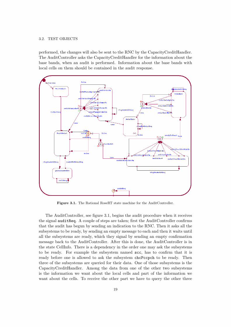
Figure 3.1. The Rational RoseRT state machine for the AuditController.
The AuditController, see figure 3.1, begins the audit procedure when it receivesthe signal auditReq. A couple of steps are taken; first the AuditController confirmsthat the audit has begun by sending an indication to the RNC. Then it asks all thesubsystems to be ready, by sending an empty message to each and then it waits untilall the subsystems are ready, which they signal by sending an empty confirmationmessage back to the AuditController. After this is done, the AuditController is inthe state CellInfo. There is a dependency in the order one may ask the subsystemsto be ready. For example the subsystem named scc, has to confirm that it isready before one is allowed to ask the subsystem chcPccpch to be ready. Thenthree of the subsystems are queried for their data. One of those subsystems is theCapacityCreditHandler. Among the data from one of the other two subsystemsis the information we want about the local cells and part of the information wewant about the cells. To receive the other part we have to query the other three
19
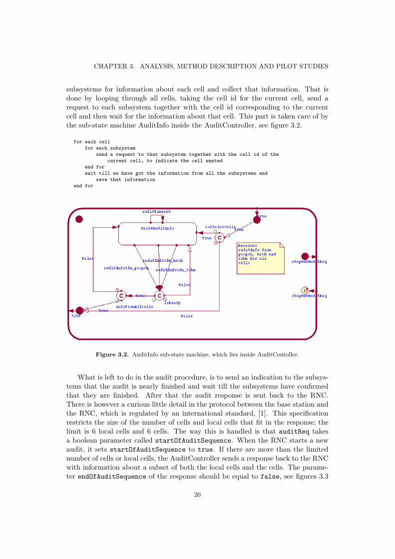
CHAPTER 3. ANALYSIS, METHOD DESCRIPTION AND PILOT STUDIES
subsystems for information about each cell and collect that information. That isdone by looping through all cells, taking the cell id for the current cell, send arequest to each subsystem together with the cell id corresponding to the currentcell and then wait for the information about that cell. This part is taken care of bythe sub-state machine AuditInfo inside the AuditController, see figure 3.2.
for each cellfor each subsystem
send a request to that subsystem together with the cell id of thecurrent cell, to indicate the cell wanted
end forwait till we have got the information from all the subsystems and
save that informationend for
Figure 3.2. AuditInfo sub-state machine, which lies inside AuditContoller.
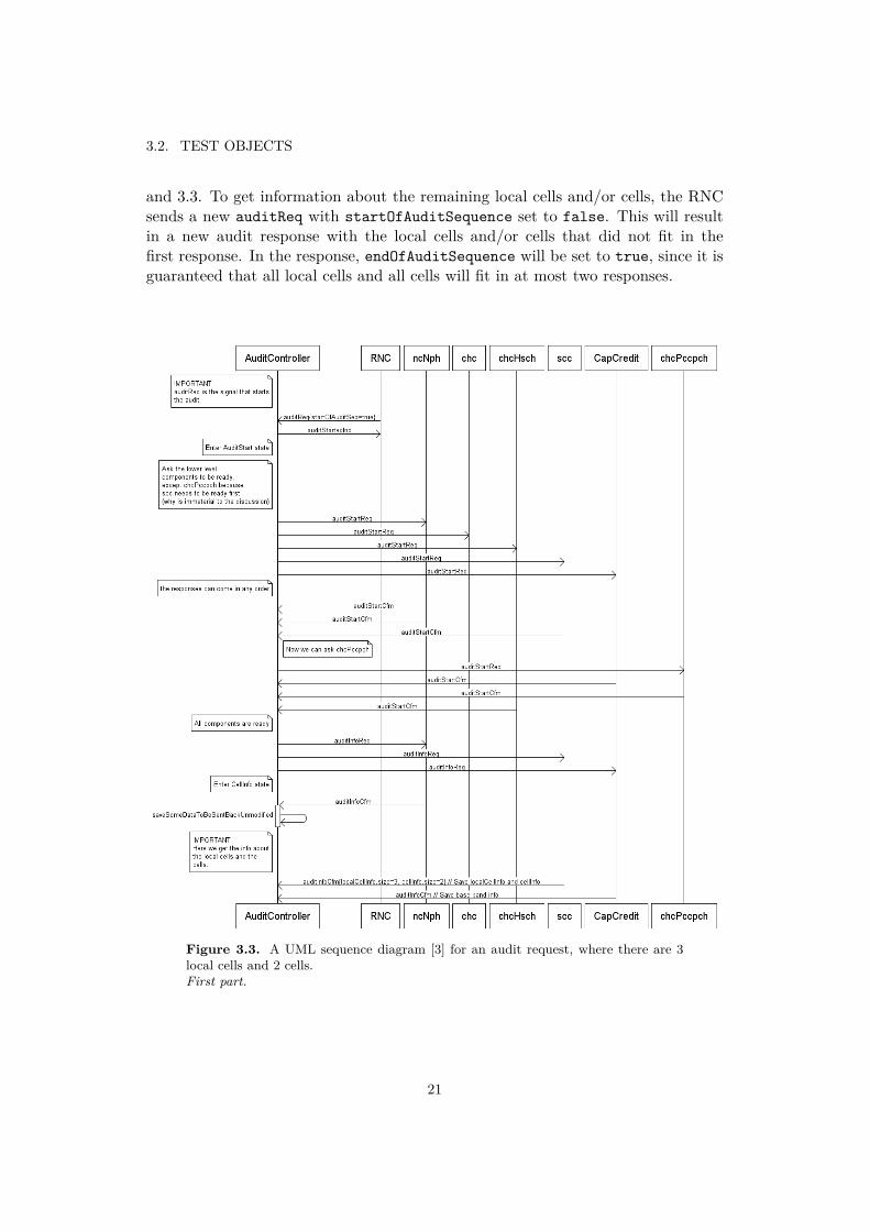
What is left to do in the audit procedure, is to send an indication to the subsys-tems that the audit is nearly finished and wait till the subsystems have confirmedthat they are finished. After that the audit response is sent back to the RNC.There is however a curious little detail in the protocol between the base station andthe RNC, which is regulated by an international standard, [1]. This specificationrestricts the size of the number of cells and local cells that fit in the response; thelimit is 6 local cells and 6 cells. The way this is handled is that auditReq takesa boolean parameter called startOfAuditSequence. When the RNC starts a newaudit, it sets startOfAuditSequence to true. If there are more than the limitednumber of cells or local cells, the AuditController sends a response back to the RNCwith information about a subset of both the local cells and the cells. The parame-ter endOfAuditSequence of the response should be equal to false, see figures 3.3
20
3.2. TEST OBJECTS
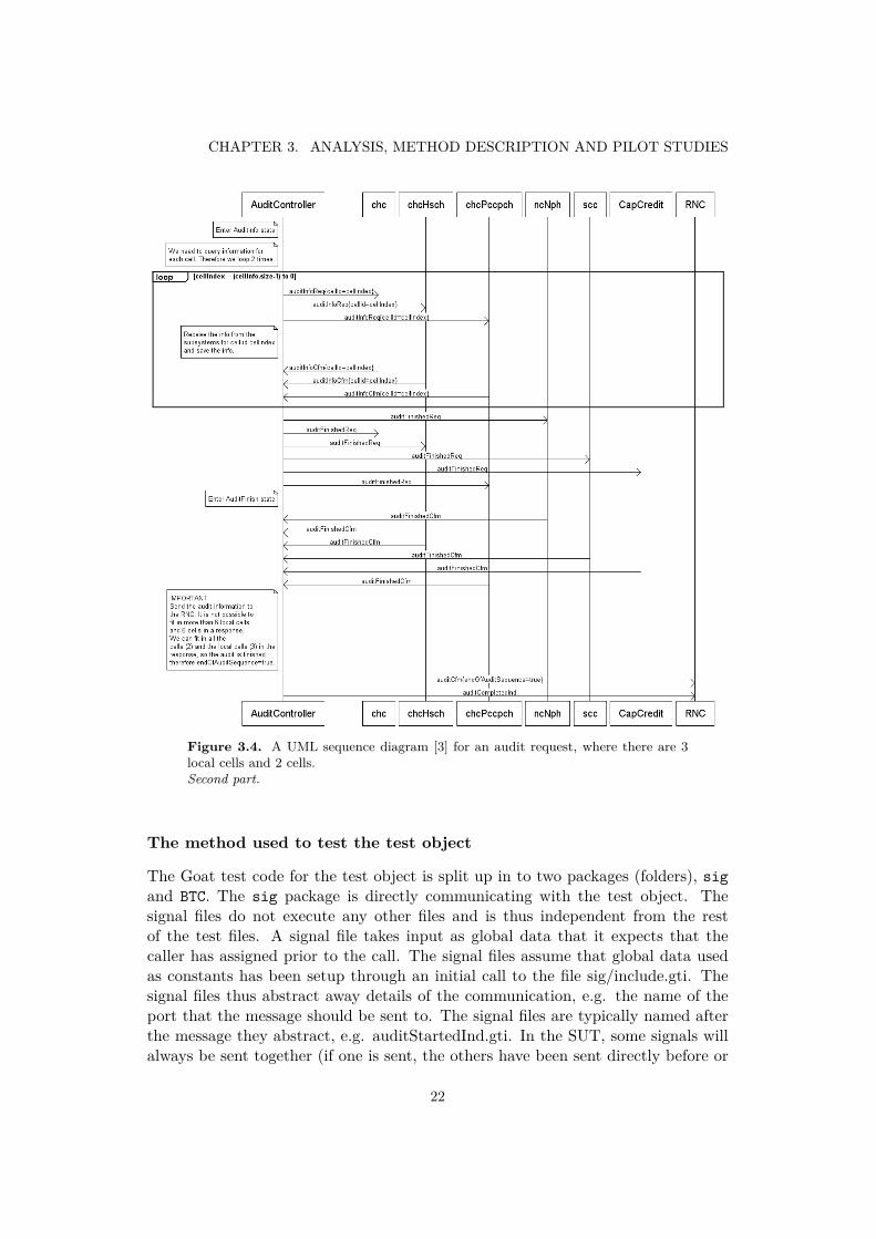
and 3.3. To get information about the remaining local cells and/or cells, the RNCsends a new auditReq with startOfAuditSequence set to false. This will resultin a new audit response with the local cells and/or cells that did not fit in thefirst response. In the response, endOfAuditSequence will be set to true, since it isguaranteed that all local cells and all cells will fit in at most two responses.
Figure 3.3. A UML sequence diagram [3] for an audit request, where there are 3local cells and 2 cells.First part.
21
CHAPTER 3. ANALYSIS, METHOD DESCRIPTION AND PILOT STUDIES
Figure 3.4. A UML sequence diagram [3] for an audit request, where there are 3local cells and 2 cells.Second part.
The method used to test the test object
The Goat test code for the test object is split up in to two packages (folders), sigand BTC. The sig package is directly communicating with the test object. Thesignal files do not execute any other files and is thus independent from the restof the test files. A signal file takes input as global data that it expects that thecaller has assigned prior to the call. The signal files assume that global data usedas constants has been setup through an initial call to the file sig/include.gti. Thesignal files thus abstract away details of the communication, e.g. the name of theport that the message should be sent to. The signal files are typically named afterthe message they abstract, e.g. auditStartedInd.gti. In the SUT, some signals willalways be sent together (if one is sent, the others have been sent directly before or
22
3.2. TEST OBJECTS
will be sent directly afterwards) and some signals are expected together. If the SUTis waiting for one of them, it is also waiting for the other. Such an example is at theend of an audit, when the SUT is waiting for all subsystems to confirm that theyhave finished, which they indicate by sending the message auditFinishedCfm. Inother words, sig/auditFinishedCfm.gti sends the message auditFinishedCfm to theAuditController, to all the ports that correspond to the ports of the AuditControllerssubsystems, except CapacityCreditHandler as it is not replaced with a stub. Somescript files contain logic that is more elaborate and can contain control structures,but the conditions of the control structures depend only on the parameters of thescript. The control structures are just used for abstraction purpose to make theinterface easier to use.
Modelling at the same abstraction level as the SUT
Most of the statechart constructs used from Rational RoseRT, have equivalents inQtronic. Thus, it is possible to make a Qtronic model that is essentially a one-to-one mapping of the Rational RoseRT implementation it is testing. At Tieto Umeå,there is no external documentation (external from the code) specifying behaviourat the abstraction level where Goat is used for testing. However, it is possible toreverse engineer the specification from the implementation, but with the risk thatsome error will be transmitted to the specification, if for example the implementa-tion somewhere erroneously sends a signal it should not send. Other errors in theimplementation may not be reflected in the reverse engineered specification i.e. an”off by one” error in the implementation [2].
From the specification, it is possible to create a reference implementation inQtronic. Obviously the Qtronic implementation is a test oracle,
A similar approach is used in fault tolerant systems, where two different groupsindependently implement a system from a specification. The input to the systemis sent into both systems and it is verified that both implementations give thesame answer. If the answer is not the same, the control system could go into someemergency state and fail safely. In the case of a control program for i.e. a subwaytrain, an appropriate action could be to stop [14].
However, using two independently implemented systems do not remove the needfor testing; it is just a safety measure if some error escaped into the shipped product.The use of reference implementations is not fool proof; an example comes from aspace rocket crash [4].
The development approach using Qtronic could be to make reference implemen-tations in Qtronic and use Qtronic to ”check” that the SUT and the reference areequivalent, without having to construct the test cases manually. This approach wasnot feasible for the AuditController, because of state space explosion during thegeneration of the test cases.
23
CHAPTER 3. ANALYSIS, METHOD DESCRIPTION AND PILOT STUDIES
Modelling at the same abstraction level as the BTC script files
Since sig does not depend on BTC, it is possible to replace BTC with new test scriptsand still use sig. The Goat language provides means to send messages and assertthat you get the correct answer, when you receive messages. Most of the files inthe sig folder, either send or receive input. A file that sends data together with amessage to the SUT, takes that data as parameters. When one expects a messageor a consecutive sequence of messages, a sig file is used to receive those messagesfrom the SUT. In most cases when a sig file receives a message from the SUT andthat message contains data, the received data is compared with the input data ofthe sig file’s parameters.
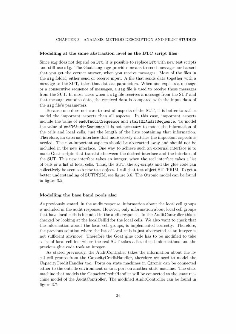
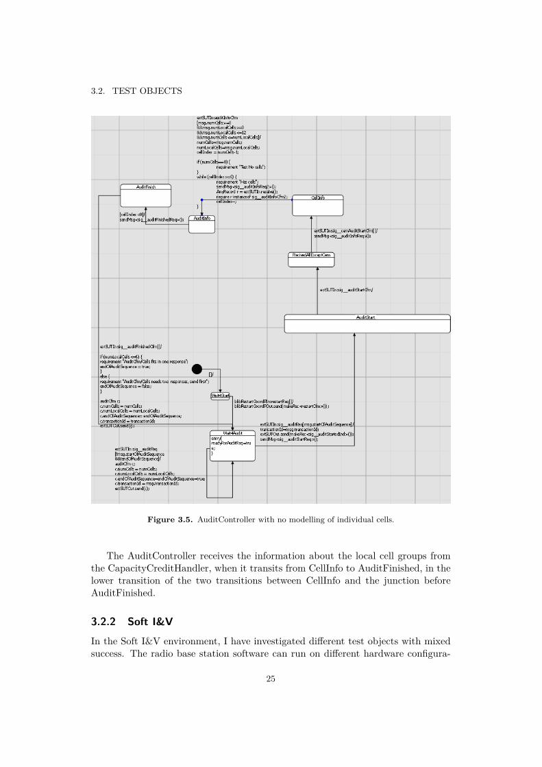
Because one does not care to test all aspects of the SUT, it is better to rathermodel the important aspects than all aspects. In this case, important aspectsinclude the value of endOfAuditSequence and startOfAuditSequence. To modelthe value of endOfAuditSequence it is not necessary to model the information ofthe cells and local cells, just the length of the lists containing that information.Therefore, an external interface that more closely matches the important aspects isneeded. The non-important aspects should be abstracted away and should not beincluded in the new interface. One way to achieve such an external interface is tomake Goat scripts that translate between the desired interface and the interface ofthe SUT. This new interface takes an integer, when the real interface takes a listof cells or a list of local cells. Thus, the SUT, the sig-scripts and the glue code cancollectively be seen as a new test object. I call that test object SUTPRIM. To get abetter understanding of SUTPRIM, see figure 3.6. The Qtronic model can be foundin figure 3.5.
Modelling the base band pools also
As previously stated, in the audit response, information about the local cell groupsis included in the audit response. However, only information about local cell groupsthat have local cells is included in the audit response. In the AuditController this ischecked by looking at the localCellId for the local cells. We also want to check thatthe information about the local cell groups, is implemented correctly. Therefore,the previous solution where the list of local cells is just abstracted as an integer isnot sufficient anymore. Therefore the Goat glue code has to be modified to takea list of local cell ids, where the real SUT takes a list of cell informations and theprevious glue code took an integer.
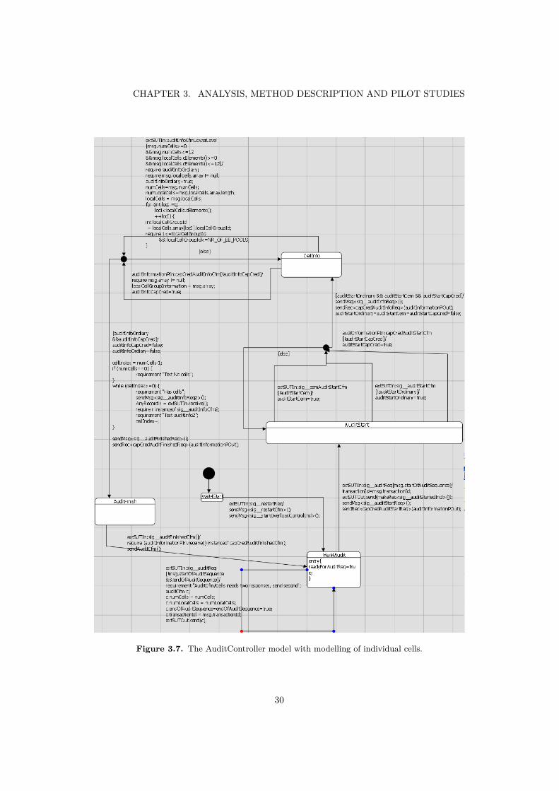
As stated previously, the AuditController takes the information about the lo-cal cell groups from the CapacityCreditHandler, therefore we need to model theCapacityCreditHandler too. Ports on state machines in Qtronic can be connectedeither to the outside environment or to a port on another state machine. The statemachine that models the CapacityCreditHandler will be connected to the state ma-chine model of the AuditController. The modified AuditController can be found infigure 3.7.
24
3.2. TEST OBJECTS
Figure 3.5. AuditController with no modelling of individual cells.
The AuditController receives the information about the local cell groups fromthe CapacityCreditHandler, when it transits from CellInfo to AuditFinished, in thelower transition of the two transitions between CellInfo and the junction beforeAuditFinished.
3.2.2 Soft I&V
In the Soft I&V environment, I have investigated different test objects with mixedsuccess. The radio base station software can run on different hardware configura-
25
CHAPTER 3. ANALYSIS, METHOD DESCRIPTION AND PILOT STUDIES
Figure 3.6. A diagram of SUTPRIM.
tions. The same test scripts can be executed on different configurations. The SoftI&V scripts are also used for regression purposes, to verify no errors are introducedat a later stage. Different configurations could have different hardware setup.
LAU - Lock and Unlock
The test object LAU is tested using Erlang, as all test objects on the Soft I&Vlevel. The name derives from the fact that it tests that the Locking and Unlockingcapability is working. LAU is testing if it is possible to lock hardware cards on thecurrent configuration. This is done by traversing through all cards on a configurationand locking them, and then unlocking them. The signals to the stub replacing thehardware are intercepted to ensure that the correct signals are sent to the hardware,following a lock or unlock operation. Signals include a command to turn on a LED(Light Emitting Diode). The dynamic structure of the components varies fromconfiguration to configuration. This could mathematically be regarded as a non-deterministic aspect of the SUT. To test LAU using Qtronic, the non-deterministicaspect of not knowing the dynamic relation of the components of the configurationwould still have to be handled in Erlang code. By implementing the enumerationof the components in the traditional way using Erlang and the testing of the actuallocking of a single component appears to be something that is plausible to implementin Qtronic. However, the messages sent to the hardware from the software, dependon the type of the component, which is also something that is non-deterministic.While it would be possible to make a model of a sole component and let it checksome constants defined in QML, which denotes the type of the modelled componentand then let the model code check the value of those constants to decide how tobehave. Qtronic could then be run with different values for those constants. Whenthe test code in Erlang is about to test a component that it has found during thetraversal, it could check the type of the component and then decide to run the
26
3.2. TEST OBJECTS
corresponding test cases generated from Qtronic. I find using Qtronic for testingthis test object is grossly verbose compared to the current way of testing this testobject. The documents explaining LAU contain use cases of LAU and they alsocontain sequence diagrams. Since the documents do not try to describe the internalsof the LAU software, the use cases and sequence diagrams naturally take the view ofthe collaborators and users of LAU. Therefore modelling how a hardware componentlike this behaves is as complicated as taking the view of the collaborators of thecomponent, which is the way it is done in traditional testing.
RAB - Radio Access Bearer
The acronym RAB stands for Radio Access Bearer. An RAB represents a connectionvia radio, between a cell phone and the RBS. There are different RABs that havedifferent properties and characteristics, depending on what the connection shouldbe used for. An RAB supporting video streaming needs more bandwidth than anRAB for a phone call.
There are tests that verify that it is possible to setup RABs of different RABtypes and to reconfigure an existing RAB to a new RAB type. An RAB type in themodel was supposed to be modelled as a state in Qtronic, with a reconfigurationmodelled as a transition between two states representing two different RAB types.Modelling N different RAB types with all possible transitions, would require mod-elling N*(N-1) different transitions, which is not feasible. Consequently, Qtronicwas turned down as a way to test configuration and reconfiguration of the RABs.
CCL - Cell Control
The Cell Control, CCL, is the test area that is responsible for management ofcell resources on a Radio Base Station. Its responsibility also includes handlinghardware failures. It is also possible for the operator to explicitly lock resources.When a hardware resource fails or gets locked, the resources that depend on it willstop working. During all these cases, the RNC has to be notified of the changes inavailable resources. Each Radio Base Station is connected to an RNC, but the RNCcan be connected to multiple Radio Base Stations. Depending on what the resourceswere capable of, different things happen when a resource becomes disabled. Thepart I have focused my analysis on, is testing when cells are affected by failuresor lock operations, specifically two use cases. Both those use cases were not verydifferent in structure. For both of those use cases to be usable, the base stationconfiguration has to have two transmission cards. How many transmission cardsthere are, cannot be controlled from the test case, as it is part of the configurationand is therefore out of the control for the test code. Therefore, the number oftransmission cards is something that is a non-deterministic aspect of the SUT, asfar as the test code is concerned. In the code for both of the test cases, someresources are first acquired. After those resources are acquired, it is possible tocheck the number of transmission cards. If the number is different from two, then
27
CHAPTER 3. ANALYSIS, METHOD DESCRIPTION AND PILOT STUDIES
we just release the resources back to the SUT and exit the test case. The pseudocode for both of the current test cases, looks roughly like this:
setup resources (step A)if there are two transmission cards, then
acquire more resources (step B)test the behaviour that should be testedrelease resources from step B
elseprint info that we skipped the test case
end ifrelease resources from step A
It would not be that hard in Qtronic to handle the problem that the numberof transmission cards is non-deterministic. In my opinion, the best way to modelthis is to provide a way to assert that things are equal in QML. In this case, wewant to assert that the number of transmission cards is equal to two. This can bedone by adding a QML record that signals that two expressions should be equal.Let us call that record AssertEqualsMessage and let it have two fields (left andright) in it. Then you can make a QML function called AssertEquals, taking twoarguments that in turn sends the AssertEqualsMessage on some special port. Thenthe ScriptingBackend should be responsible for handling the AssertEqualsMessageaccordingly, not as a normal message. The problem of releasing the appropriateresources in all cases is non-trivial. To assist and make it as automatic as possible,I suggest borrowing a programming paradigm commonly used in C++; called Re-source Acquisition Is Initialization (RAII) [16]. My suggestion is that the libraryshould provide a type parameterized QML record called RAIIMessage with twofields. When a message is received that corresponds to an allocation of somethingthat should be released later, then RAIIMessage should be used. The first fieldshould be the message that corresponds to the allocation and it should be executedwhen the RAIIMessage is received. The second field is the message that should besent later to the SUT to deallocate the resource that corresponds to the allocationrepresented by the first field of the RAIIMessage. To execute the second messagein the correct place, you can use the following special handling of RAIIMessage andAssertEqualsMessage in the Scripting Backend.
# assume we have a stack of lists of messages, called deallocationStack
push an empty list to deallocationStack
for each message, msgif no more messages, then
# time to end the nested if statements and execute the deallocationsfor ever
for each message, m in deallocationStack.topadd the code to execute m
end fordeallocationStack.pop()if deallocationStack is empty then
break forend if
28
3.2. TEST OBJECTS
# the end if will match an else added in the end of the end of the# AssertEqualsMessage branchadd the code ’’end if’’
end forelse if message is of type RAIIMessage, then
handle the first field of RAIIMessage as a regular messageadd the second field to the top list of deallocationStack
else if message is of type AssertEqualsMessagepush an empty list to deallocationStackadd the code ’’if msg.left != msg.right then’’add the code ’’print ’this test case is not vaild because ’’’ +
’’+ msg.left + ’ is not equal to ’ + msg.right’’add the code ’’else’’
elsehandle as message as a normal message
end ifend for
29
CHAPTER 3. ANALYSIS, METHOD DESCRIPTION AND PILOT STUDIES
Figure 3.7. The AuditController model with modelling of individual cells.
30
Chapter 4
Conclusion
I do not recommend adoption of Model-Based Testing, MBT, using Qtronic, forTieto Umeå on any of the test areas I have studied. Below I will point out positiveand negative aspects of using Qtronic.
The main reason is that Basic test level is on a too low level to be suitable forMBT and therefore nearly the whole test object has to be modelled. The test objectsI analysed in Soft I&V are non-deterministic and had other different properties thatmade testing using Qtronic impossible or unfeasible.
Traditional test cases are on a more concrete level and more tangible than theimplementation of the SUT, whereas a model used for Model-Based Testing is ona higher level of abstraction, and possibly on the same level or higher than theimplementation of the SUT. When testing is done, it is desirable if errors that arelikely to be made during implementation are not very likely also to be made inthe test code, to avoid errors escaping discovery during testing. For testing oncomponent level or integration level, a QML model is typically more similar to theimplementation than the test cases. After all a QML model is modelling the SUTand is essentially a reference implementation, while test cases can be thought ofas clients of the SUT. Therefore, I believe it is more likely that the same errorsthat exist in the SUT are introduced in a model, than in test cases, at least forcomponent- and integration level testing. The fact that component level testingis commonly done by the same developer who did the implementation, makes thisparagraph even more true in my opinion.
In Tieto Umeå and in many organisations there is little or no detailed externaldocumentation on the component level. It can be tempting to blame the organi-sations for this fact, if one does not know very much about software development.However, having detailed external documents has its own problems and costs andthe cost can be much higher than the benefit. The lack of external documentationmakes the risk even higher, of introducing the same errors and bugs in the modelthat existed in the SUT.
My aversion of MBT for component testing and integration testing at a lowabstraction level, is a position to some extents held by the academic community. In
31

CHAPTER 4. CONCLUSION
[11] Dr. Bruno Legeard who is a recognized expert in the academic MBT communityand the CTO of Smartesting which is a competitor of Conformiq, says: ”Regardingthe testing level, the current mainstream focus of MBT practice is system testingand acceptance testing, rather than unit or module testing. Integration testing isconsidered at the level of integration of subsystems.”
Soft I&V, which is a more appropriate level for MBT than Basic test, had otherissues and problems that hindered the application of MBT using Qtronic. Refer tosection 3.2.2 and its subsections for details.
There exist plans at Tieto Umeå to migrate from Goat to the Ruby programminglanguage, for testing at the Basic test level. If that project is brought to realisation,then a custom tool will be implemented that can translate Goat code to Ruby code.Existing QML models for Basic test should work without any changes, as long as aQtronic Backend for Ruby is constructed that can understand the special messagesin the QML Goat library. Therefore the migration from Goat to Ruby, should notaffect the decision if Qtronic should be adopted for Basic test. A migration fromGoat to Ruby will most likely prove to improve the structure of the future test code,since Goat is a quite limited language.
If Qtronic is introduced, it is desirable that the organisation is not locked intoQtronic with very high exit barriers. Qtronic generates scripts, generated scriptscan be used for regression testing, therefore no Qtronic license is needed to executealready generated scripts.
If existing scripts have to be extended, understanding the existing script is quitefeasible. Among other things, when a requirement stated in the model is coveredin a generated test case, the requirement will be added to the script as a comment.However, no control structures or loops will be generated. Therefore, if a large arrayshould be populated in a script, that is done without a loop. This could possiblesometimes make the scripts less manageable for humans.
In the AuditController in section 2.2.3, there is a signal (auditStartedInd)that is sent from the SUT every time the SUT receives the signal auditReq withthe parameter startOfAuditSequence set to true. Nearly all test cases will sendan auditReq with startOfAuditSequence set to true, at least once. The code forthat behaviour resides in one place in the SUT. Assuming the AuditController isnot supposed to send auditStartedInd any more, the developer needs to remove onlya single line of code in the SUT. The corresponding change for the QML model,see section 3.2.1, is also the removal of a single line of QML code. However, usingtraditional testing, nearly all scripts would be affected by the change, which is aconsiderably higher effort than the corresponding change when using Qtronic.
Comprehending the traditional test code can be problematic if one is new tothe test object, since there can be thousands of scripts per test object. When usingQtronic, it is likely that one makes errors either in the model or in the implemen-tation, which will probably appear when a generated test case fails. Then oneprobably wants to find the execution path through the model up to the place whereit failed. The way this is done is by looking into the place in the Goat code whereit failed, and find the corresponding test step in the test case in Qtronic. When
32
looking at the message type of the failing message and the adjacent messages, it isnot that hard to find the corresponding place in the test case in Qtronic. Whenthis is done you can observe in Qtronic what transitions have been covered for thattest case (see figure 2.2) and where in the model the message was received or sentthat induced the failure.
During software development, it is quite common that multiple versions of thesame code exist. This can happen when several developers work in the same placein a code base or when multiple versions are maintained. It is common that twoversions of source files have to be merged. When the code is textual, this is quiteconveniently done with the assistance of tools, which find the difference between theversions. The graphical part of a QML model is saved as an XML file on disc. It isplausible that two versions of a QML model have to be merged. Merging them willnot be impossible since humans can understand XML; however it will be a little bitof a hassle, without some dedicated tool.
33

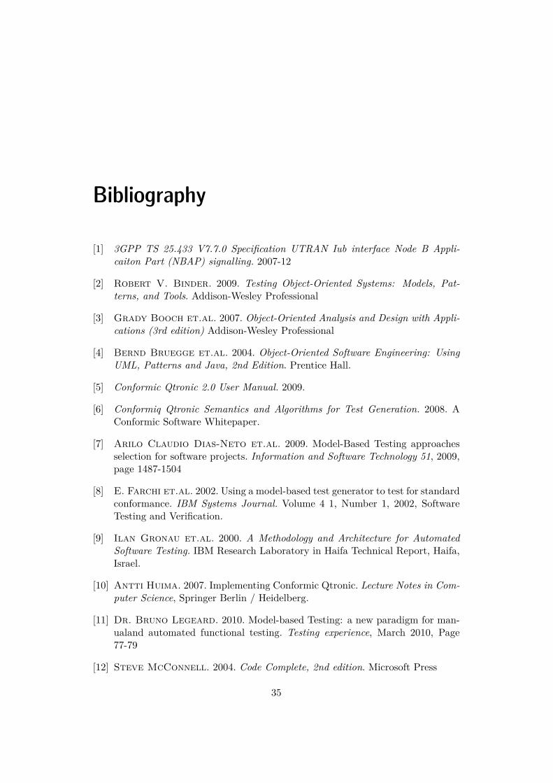
Bibliography
[1] 3GPP TS 25.433 V7.7.0 Specification UTRAN Iub interface Node B Appli-caiton Part (NBAP) signalling. 2007-12
[2] Robert V. Binder. 2009. Testing Object-Oriented Systems: Models, Pat-terns, and Tools. Addison-Wesley Professional
[3] Grady Booch et.al. 2007. Object-Oriented Analysis and Design with Appli-cations (3rd edition) Addison-Wesley Professional
[4] Bernd Bruegge et.al. 2004. Object-Oriented Software Engineering: UsingUML, Patterns and Java, 2nd Edition. Prentice Hall.
[5] Conformic Qtronic 2.0 User Manual. 2009.
[6] Conformiq Qtronic Semantics and Algorithms for Test Generation. 2008. AConformic Software Whitepaper.
[7] Arilo Claudio Dias-Neto et.al. 2009. Model-Based Testing approachesselection for software projects. Information and Software Technology 51, 2009,page 1487-1504
[8] E. Farchi et.al. 2002. Using a model-based test generator to test for standardconformance. IBM Systems Journal. Volume 4 1, Number 1, 2002, SoftwareTesting and Verification.
[9] Ilan Gronau et.al. 2000. A Methodology and Architecture for AutomatedSoftware Testing. IBM Research Laboratory in Haifa Technical Report, Haifa,Israel.
[10] Antti Huima. 2007. Implementing Conformic Qtronic. Lecture Notes in Com-puter Science, Springer Berlin / Heidelberg.
[11] Dr. Bruno Legeard. 2010. Model-based Testing: a new paradigm for man-ualand automated functional testing. Testing experience, March 2010, Page77-79
[12] Steve McConnell. 2004. Code Complete, 2nd edition. Microsoft Press
35
BIBLIOGRAPHY
[13] Jeff Offutt et.al. 1999. Generating Tests from UML Specifications.«UML»99’, LNCS 1723, Page 416-429
[14] Bruce Powel Douglass 2002. Real-Time Design Patterns: Robust ScalableArchitecture for Real-Time Systems. Addison-Wesley Professional
[15] Ian Sommerville. 2004. Software Engineering, 7th edition. Addison Wesley.
[16] Bjarne Strostrup. 2000. The C++ Programming Language: Special EditionAddison-Wesley Professional
[17] Heikki Kaaranen et.al. 2005. UMTS Networks - Architecture, Mobility andServices, 2nd edition. Wiley
[18] Mark Utting et.al. 2006. A taxanomy of Model-based Testing. TechnicalReport 04/2006. Department of Computer Science, The University of Waikato,New Zealand, April 2006.
[19] Eddie Jaffuel. 2006. LEIRIOS Test Generator: Automated Test Generationfrom B Models. Lecture Notes in Computer Science 4355, Springer Berlin /Heidelberg
36

TRITA-CSC-E 2010:058 ISRN-KTH/CSC/E--10/058--SE
ISSN-1653-5715
www.kth.se