Embed Size (px)
Citation preview
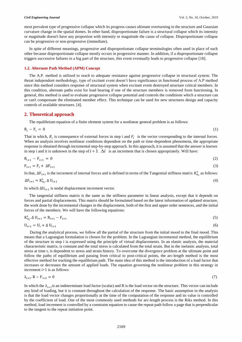
Available online at www.CivileJournal.org
Civil Engineering Journal
Vol. 5, No. 10, October, 2019
2167
Evaluation of Progressive Collapse Performance in Double layer
Diamatic Domes
Javid Rezania a*, Peyman Torkzadeh b a M.Sc. of Structural Engineering, Department of Civil Engineering, Faculty of Engineering, Shahid Bahonar University of Kerman,
Kerman, Iran.
b Associate Prof., Department of Civil Engineering, Faculty of Engineering, Shahid Bahonar University of Kerman, Kerman, Iran.
Received 19 February 2019; Accepted 02 August 2019
Abstract
Double-layer spatial domes are one of the most common spatial structures, the stability and progressive collapse of which
are of great importance in design, construction and maintenance of such special structures. In this paper considering three
loading cases and two types of support conditions, the collapse behaviour of double layer Diamatic dome has been
investigated utilizing non-linear static analysis and alternate path method usage. In order to modelling compressive member
behaviour, effective buckling modes have been obtained by eigenvalue buckling analysis for all of the members. Behaviour
of compressive members has been obtained via definition of initial imperfection and non-linear static analysis. Riks arc-
length method has been utilized for non-linear static analysis. The numerical results have indicated that reducing the
number of the supports and focusing of load in a local area of the dome extremely impact on its vulnerability to failure,
as in similar loading condition, decreasing the number of the supports reduces the capacity of damage resistance in spatial
domes up to 50 percent. Investigating some models has shown that removing the critical members of the top layer has little
effect on load-bearing capacity of the dome and it causes a slight failure in the structure. In this condition, structural
redundancy can be considered equal to static indeterminacy. Load bearing capacity of the structure decreased up to 39
percent when compressive members of the web and bottom layers were removed. In this condition, the structure failure is
considered moderate.
Keywords: Progressive Collapse; Alternate Path Method; Nonlinear Static Analysis; Double Layer Spatial Dome.
1. Introduction
One of the oldest impressive structural systems, domes which are formed from single or multi-layer bar elements,
have geometrical curvature in longitudinal direction and ordinate. This structures are utilized to cover the large span like
exhibitions, worships, stadiums and large halls. These specific structures create an unobstructed inner space and are so
economical in material usage [1]. Being lighter compared to more conventional structural forms, high degree of
redundancy, suitable and adequate stiff and consistent performance in load bearing made spatial domes particular and
strategic structures that present very ideal utility in essential situations like destructive earthquakes or when it is needed
to find a vast and safe shelter in urgent conditions. Research on progressive collapse began in 1968 after Ronan Point
apartment destruction but incident of world trade towers in 2001 actuated researchers to evaluate of important buildings
performance to abnormal loads and progressive collapse. These magnificent structures have always attracted engineers
and designers because of their low weight, appropriate stiffness, ideal seismic performance, amazing beauty, covering
* Corresponding author: [email protected]
http://dx.doi.org/10.28991/cej-2019-03091402
© 2019 by the authors. Licensee C.E.J, Tehran, Iran. This article is an open access article distributed under the terms and conditions of the Creative Commons Attribution (CC-BY) license (http://creativecommons.org/licenses/by/4.0/).

Civil Engineering Journal Vol. 5, No. 10, October, 2019
2168
of vast spaces without utilizing interior supports and etc. In recent years, many researchers have studied the collapse of
spatial structures specially reticulated domes. It was believed that multilayer spatial structures do not cause concern
about progressive collapse due to multiplicity of members and the high degree of redundancy .as a result, most researches
have been conducted on single-layer domes. Comparing presented methods by GSA and UCF, the alternate path method
is a more capable and more realistic method among researchers. This method evaluates the resistance and stability of
the structure against progressive collapse by removing a member which informs the designer about resistance potential
of structure against collapse. The alternate path method has been formed redundancy of structure. Availability of the
alternate load-bearing elements and also alternate paths for load transition from applied position to a resistance point,
describe concept of redundancy. Numerous studies about progressive collapse of building structures against the absence
of enough research about spatial structures in spite of their vast functions is obvious. Researchers call large spatial
structures symbolic buildings carrying high social and economic importance which offer various grounds to research
and studying encounter by abnormal loads [2].
Sun and et al. in 2012 evaluated structure progressive collapse process with static and dynamic behaviour modelling
involving fire condition in steel structures [3]. Feng in 2009 presented his studying on a 20 story building by applying
both material and geometric nonlinear behaviours [4]. Low and et al. in 2013 did numerical modelling to predict collapse
process in tall reinforced concrete buildings in strong earthquakes based on FEM*. Using IDA† and with concentrate on
their near-collapse behaviour [5]. Shen and et al. (2015) [6] applied collapse seismic analysis in ordinary buildings that
their lateral loading system had been elected non-ductile concentric braced frame‡. With progressive collapse dynamic
modelling, Iriban and et al. (2011) [7] evaluated impact of both material and time of column elimination parameters in
progressive collapse of a multi-storey reinforced concrete frame. Pertained to bridges, Jen and et al. (2013) [8], Kiyaminf
and et al. (2015) [9], and Miyachi and et al. (2009) [10] studied progressive collapse in a stone arcing bridge, multi span
bridge in Jozho city of China and two truss bridge with the span length of 200 meters; respectively.
In distinct types of buildings and bridges, progressive collapse issue has been evaluated widely with various methods
and appliances by considering widespread and effective parameters in structure performance. But studying this topic in
spatial structures which deals with increasing development in these structures has become more serious and significant
recently. First serious investigation in this way and consequently presenting the most prevalent use of progressive
collapse potential evaluation method namely Load Alternate Path Method§, was conducted by Smith in 1988 for first
time in evaluation of double layer grids. While this method has been utilized for framed structures already [11]. Diverse
studies and researches in progressive collapse of spatial structures have been performed by various researchers
afterward. [12-16].
Recently in 2019, Li-min Tian et al. [17] tested a commonly used reinforcing technology on four substructures that
were abstracted from a single layer spatial grid structure. They proposed a modified optimization method for two typical
failure mechanisms. Before it, Rezania and Torkzadeh (2015) [18] have been described usage of collapse constraints in
the context of progressive failure. Li-Min Tian et al. (2018) [19] evaluated an experimental study on the anti-collapse
mechanisms of long-span single-layer spatial grid structures. Their experimental results, including the load–
displacement responses, sequences and modes of failure, and strain measurements were analysed, and the anti-collapse
mechanism was examined. In addition, they conducted a numerical simulation for a single member derived from the test
specimens. Four substructure experiments were conducted for a single layer spatial grid structure to investigate the
typical failure mechanisms [20]. Based on their experimental results, a numerical simulation using multi-scale
technology was calibrated. In order to prevent typical failures, they proposed a novel method including kinked steel pipe
reinforcement and extra member reinforcement. It validated by a numerical simulation. Vitaliy et al. (2017) [21]
calibrated three finite element deletion strategies for use in modeling fracture and material separation in spatial steel
structures. They compared these methods for their capability to predict the location of fracture initiation and the direction
of fracture propagation. Each strategy is based on micromechanical fracture behavior of the material and is independent
of the overall structure type. Ye and Qi (2017) [22] simulate the complicated mechanical behaviour that occur in the
collapse process of structures, extended DEM to study the continuum structures. Their proposed method is applied to
the collapse simulation process of single-layer reticulated dome models. Compared with the shaking table test, it is
observed that the simulation results including the collapse process and the fracture location of joints, agree well with the
experimental phenomenon.
1.1. Progressive Collapse Concept
Collapse, an ultimate limit state when structure is subjected to abnormal loads which one of the most famous of them
is progressive collapse. "Disproportionate" phrase is next to "progressive" term. In general, progressive collapse means
diffusion of a wide and chain collapse that is caused by damage to fairly small part of structure. Domino collapse, the
* Finite element method † Incremental dynamic analysis ‡ C.B.F. §A.P.M.
Civil Engineering Journal Vol. 5, No. 10, October, 2019
2169
most prevalent type of progressive collapse which its progress causes ultimate overturning in the structure and Gaussian
curvature change in the spatial domes. In other hand, disproportionate failure is a structural collapse which its intensity
or magnitude doesn't have any proportion with intensity or magnitude the cause of collapse. Disproportionate collapse
can be progressive or non-progressive (immediate).
In spite of different meanings, progressive and disproportionate collapse terminologies often used in place of each
other because disproportionate collapse mostly occurs in progressive manner. In addition, if a disproportionate collapse
triggers successive failures in a big part of the structure, this event eventually leads to progressive collapse [18].
1.2. Alternate Path Method (APM) Concept
The A.P. method is utilized to reach to adequate resistance against progressive collapse in structural system. The
threat independent methodology, type of excitant event doesn’t have significance in functional process of A.P method
since this method considers response of structural system when excitant event destroyed structure critical members. In
this condition, alternate paths exist for load bearing if one of the structure members is removed from functioning. In
general, this method is used to evaluate progressive collapse potential and controls the conditions which a structure can
or can't compensate the eliminated member effect. This technique can be used for new structures design and capacity
controls of available structures. [4].
2. Theoretical approach
The equilibrium equation of a finite element system for a nonlinear general problem is as follows:
Ri − Fi = 0 (1)
That in which, 𝑅𝑖 is consequence of external forces in step i and 𝐹𝑖 is the vector corresponding to the internal forces.
When an analysis involves nonlinear conditions dependent on the path or time-dependent phenomena, the appropriate
response is obtained through incremental step-by-step approach. In this approach, it is assumed that the answer is known
in step i and it is unknown in the step of 1i . i is an increment that is chosen appropriately. Will have:
Ri+1 − Fi+1 = 0 (2)
Fi+1 = Fi + ∆Fi+1 (3)
In that, ∆Fi+1 is the increment of internal forces and is defined in terms of the Tangential stiffness matrix 𝐾𝑢𝑖𝑡 as follows:
∆Fi+1 = Kuit . ∆ Ui+1 (4)
In which ∆Ui+1 is nodal displacement increment vector.
The tangential stiffness matrix is the same as the stiffness parameter in linear analysis, except that it depends on
forces and partial displacements. This matrix should be formulated based on the latest information of updated structure,
the work done by the incremental changes in the displacement, both of the first and upper order sentences, and the initial
forces of the members. We will have the following equations:
Kuit . ∆ Ui+1 = Ri+1 − Fi+1 (5)
Ui+1 = Ui + ∆ Ui+1 (6)
During the analytical process, we follow all the partial of the structure from the initial mood to the final mood. This
means that a Lagrangian formulation is chosen for the problem. In the Lagrangian incremental method, the equilibrium
of the structure in step i is expressed using the principle of virtual displacements. In an elastic analysis, the material
characteristic matrix, is constant and the total stress is calculated from the total strain. But in the inelastic analysis, total
stress at time t, is dependent to stress and strain history. To overcome the divergence problem at the ultimate point and
follow the paths of equilibrium and passing from critical to post-critical points, the arc-length method is the most
effective method for tracking the equilibrium path. The main idea of this method is the introduction of a load factor that
increases or decreases the amount of applied loads. The equation governing the nonlinear problem in this strategy in
increment i+1 is as follows:
λi+1. R − F+1i = 0 (7)
In which the λi+1is an indeterminate load factor (scalar) and R is the load vector on the structure. This vector can include
any kind of loading, but it is constant throughout the calculation of the response. The basic assumption in the analysis
is that the load vector changes proportionally at the time of the computation of the response and its value is controlled
by the coefficient of load. One of the most commonly used methods for arc-length process is the Riks method. In this
method, load increment is controlled by a constraint equation to cause the repeat path follow a page that is perpendicular
to the tangent to the repeat initiation point.

Civil Engineering Journal Vol. 5, No. 10, October, 2019
2170
3. Collapse Modeling and Analysis
Double layer spatial domes have more rigidity compared to single layer domes. This issue has caused the assumption
that double layer structures are resistant to applied damages and don't need special investigation. This is while that this
spatial structures are at risk of progressive collapse due to production and design errors, over loading, extreme local
loads, inappropriate maintenance, length of thin members, unfit connections and etc. In this paper, collapse behavior
studying of double layer spatial domes in special load and support conditions have been conducted based on similar
idea. In dome structures to discover snap-throw event conditions, researchers have presented diverse types of loadings
[23] which among them three critical loading cases that can simulate real conditions for progressive collapse occurrence
have been selected in evaluation of structure collapse performance. Design of structure has been performed for these
loads and two perimeteral and meridional support conditions. Static analysis of collapse has been done utilizing alternate
path (AP) method and with considering both material and geometrical nonlinear behaviour for a double layer Diamatic
dome using finite element software ABAQUS. For nonlinear equilibrium equations solving, Arc-length Riks method
has been utilized. For collapse analysis, the process of below has been done by ABAQUS software in a step by step
manner:
For each member effective modes of buckling have been obtained from Eigenvalues buckling analysis. Initial
imperfection modeling equal to 0.001 times the length of the member has been extracted from linear combination
of these modes.
After applying the imperfection and by considering large deformations, behavior of compressive members has
been taken from nonlinear analysis and so ideal stress-strain diagram of the members has been traced. Full Elastic-
Plastic bilinear behavior of steel has been used for tensile members behavior modeling (Figure 4).
Critical members of the structure have been specified by linear static analysis and based on maximum compressive
force in each model. Three critical members have been determined for each model (Figure 8).
Geometrical and material nonlinear static analysis have been conducted on every six intact models .The
undamaged model is the structure without critical member elimination.
By elimination of each critical member, nonlinear static analysis with AP method has been performed in every
model (Figures 9 to 14).
To overcome divergence problem in limited point in nonlinear static analysis, the Riks Arc-Length method has been
used to follow the equilibrium paths and pass critical points to post-critical points. In this method a constraint equation
controls the load increments.
4. Experimental Study
A double layer Diamatic spatial dome with external span of 20 m and height of 5 m has been studied (Figure 1) and
its configuration has been conducted using FORMIAN software (Figure 2).
Figure 1. Section of the dome

Civil Engineering Journal Vol. 5, No. 10, October, 2019
2171
This structure has been evaluated in both perimeter and meridional support conditions which each of them is under
three critical-load conditions (Figure 3). Diverse models properties of the structure has been presented in Table 1. To
equate the conditions, one type of hollow tubular section in five different lengths adaptable with British Standard (B.S)
has been utilized in every six models according to Table 2. Supports have been located, in perimeter support conditions
at every nodes of last ring of bottom layer of the dome and in meridional support conditions, at two nodes of last ring of
bottom layer in two sides of top layer meridian lines. In meridional support conditions compared to perimeter support
conditions 10 supports are eliminated. The models with perimeter or peripheral supports and the models with meridional
supports are identified by DP* and DM† phrases respectively.
Figure 2. Configuration of the dome: a-Assembled dome; b-Bot layer; c- Web layer; d- Top layer
Three critical-load conditions that have used which consist of:
A vertical concentrated load on crown node that applied to structure increasingly (sum of the dead and snow loads).
Constant concentrated loads on all the nodes of dome (dead load "D") and increasing concentrated load on the
crown node (snow load "S").
Constant concentrated loads on all the nodes of dome (dead load) and increasing concentrated load on the middle
node of a sector of the top layer of the dome (snow load).
All the loads are applied to structure at the same time.
Table 1. Analysis models properties
Title of the model The support conditions The Loading conditions
DPC Perimeter D*&S** at crown node
DMC Meridional D&S at crown node
DPUC Perimeter D at whole nodes & S at crown node
DMUC Meridional D at whole nodes & S at crown node
DPUN Perimeter D at whole nodes & S at mid node
DMUN Meridional D at whole nodes & S at mid node
D*: Dead load; S**: Snow load
* Dome with Perimeter Supports † Dome with Meridional Supports
(a)
(b)
(d)
(c)

Civil Engineering Journal Vol. 5, No. 10, October, 2019
2172
Section sufficiency control for all cases have been conducted in SAP 2000 software according to limited design
LRFD criteria of AISC-360-10 code while considering the reduce resistance factor φ=0.9 for both compressive and
tension modes.
(a) (b)
(c) (d)
(f)

Civil Engineering Journal Vol. 5, No. 10, October, 2019
2173
Figure 3. Support and Loading conditions of the dome: (a) Bot layer plan in DP mode; (b) The dome plan in DP mode; (c)
Bot layer plan in DM mode; (d) The dome plan in DM mode; (e) Concentrated loading at the crown node; (f) Uniform dead
load at whole & dead and live concentrated load at the crown node; (g) Uniform dead load at whole & dead and live
concentrated load at the mid node.
The gravity load combinations of ASCE-07 code are used for load cases. Gravity acceleration is equal to 9.81 m/𝑠2
and St-37 with presented properties in Table 3 is used for material.
Dead and snow loads are equal to 50 kgr/m2 and 200 kgr/m2 respectively and gravity load combinations are: (1.4D,
1.2 D + 1.6 S)
Table 2. Properties of the structure members
Type Profile (mm) The dome layer Section area (mm2) Slender factor (L/r)
I CHHF 273 × 16 Top
12918.23 32.95
II CHHF 273 × 16 12918.23 38.45
III CHHF 273 × 16
Web
12918.23 21.97
IV CHHF 273 × 16 12918.23 16.48
V CHHF 273 × 16 12918.23 27.46
III CHHF 273 × 16 Bot
12918.23 21.97
IV CHHF 273 × 16 12918.23 16.48
Table 3. Steel material properties
Young’s modulus
E
(Kgr/m2)
Mass density
ρ
(Kgr/m3)
Yield stress
Fy
(Kgr/m2)
Ultimate stress
Fu
(Kgr/m2)
2.1×10¹⁰ 7850 2.4×10⁷ 3.6×10⁷
5. Collapse nonlinear static analysis
The Stress-strain behavior of the members presented in Figure 4.
Figure 4. Stress-strain behaviour modelling of the structure members
(e) (g)

Civil Engineering Journal Vol. 5, No. 10, October, 2019
2174
A linear analysis has been conducted in each load condition and a critical member has been chosen in every layer of
the dome based on maximum compressive stress. The results presented in Figures 5 to 8.
a b c
d e f
Figure 5. Linear static analysis for bot layer under different loading in Table 1: a. DPC- b. DPUC- c. DPUS- d. DSC- e.
DSUC- f. DSUS
a b c
d e f
Figure 6. Linear static analysis for web layer under different loading in Table 1: a. DPC- b. DPUC- c. DPUS- d. DSC- e.
DSUC- f. DSUS

Civil Engineering Journal Vol. 5, No. 10, October, 2019
2175
a b c
d e f
Figure 7. Linear static analysis for top layer under different loading in Table 1: a. DPC- b. DPUC- c. DPUS- d. DSC- e.
DSUC- f. DSUS
Figure 8. The critical members of each model: a-Bot layer; b-Web layer; c-Top layer
(a)
(b)
(c)
Civil Engineering Journal Vol. 5, No. 10, October, 2019
2176
0
200000
400000
600000
800000
1000000
1200000
1400000
0 0.02 0.04 0.06 0.08
No
da
l lo
ad
(k
gr)
Displacement of crown node (m)
Intact
Damaged-Top
Damaged-Web
Damaged-Bot
0
5000
10000
15000
20000
25000
30000
35000
0 0.005 0.01 0.015 0.02 0.025
No
da
l lo
ad
(k
gr)
Displacement of crown node (m)
Intact
Damaged-Top
Damaged-Web
Damaged-Bot
0
10000
20000
30000
40000
50000
60000
0 0.01 0.02 0.03 0.04
No
da
l lo
ad
(k
gr)
Displacement of crown node (m)
Intact
Damaged-Top
Damaged-Web
Damaged-Bot
0
5000
10000
15000
20000
25000
30000
0 0.005 0.01 0.015 0.02 0.025
No
da
l lo
ad
(k
gr)
Displacement of crown node (m)
Intact
Damaged-Top
Damaged-Web
Damaged-Bot
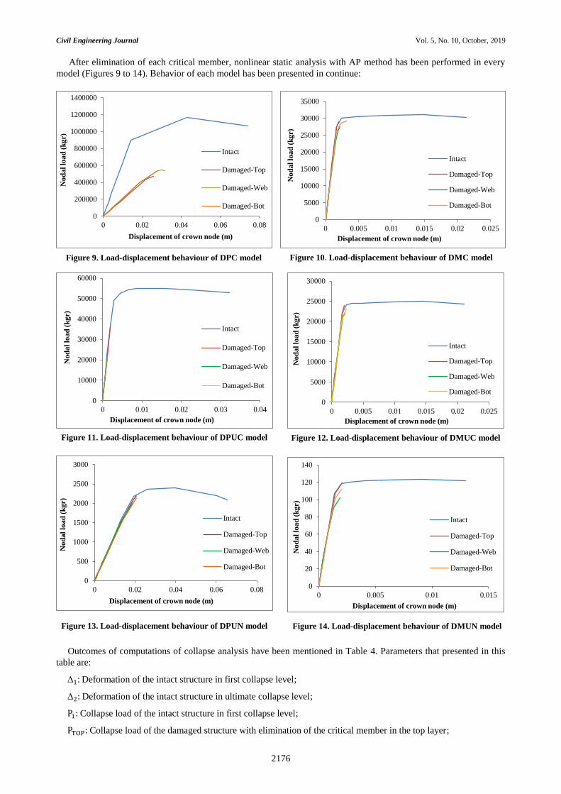
After elimination of each critical member, nonlinear static analysis with AP method has been performed in every
model (Figures 9 to 14). Behavior of each model has been presented in continue:
Outcomes of computations of collapse analysis have been mentioned in Table 4. Parameters that presented in this
table are:
Δ1: Deformation of the intact structure in first collapse level;
Δ2: Deformation of the intact structure in ultimate collapse level;
P1: Collapse load of the intact structure in first collapse level;
PTOP: Collapse load of the damaged structure with elimination of the critical member in the top layer;
0
500
1000
1500
2000
2500
3000
0 0.02 0.04 0.06 0.08
No
da
l lo
ad
(k
gr)
Displacement of crown node (m)
Intact
Damaged-Top
Damaged-Web
Damaged-Bot
0
20
40
60
80
100
120
140
0 0.005 0.01 0.015
No
da
l lo
ad
(k
gr)
Displacement of crown node (m)
Intact
Damaged-Top
Damaged-Web
Damaged-Bot
Figure 9. Load-displacement behaviour of DPC model Figure 10. Load-displacement behaviour of DMC model
Figure 11. Load-displacement behaviour of DPUC model Figure 12. Load-displacement behaviour of DMUC model
Figure 13. Load-displacement behaviour of DPUN model Figure 14. Load-displacement behaviour of DMUN model
Civil Engineering Journal Vol. 5, No. 10, October, 2019
2177
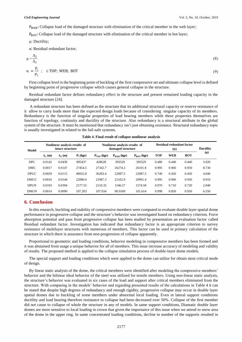
PWEB: Collapse load of the damaged structure with elimination of the critical member in the web layer;
PBOT: Collapse load of the damaged structure with elimination of the critical member in bot layer;
µ: Ductility;
α: Residual redundant factor;
µ =Δ2
Δ1
(8)
α =p
i
p1
; i: TOP; WEB; BOT (9)
First collapse level is the beginning point of buckling of the first compressive set and ultimate collapse level is defined
by beginning point of progressive collapse which causes general collapse in the structure.
Residual redundant factor defines redundancy effect in the structure and present remained loading capacity in the
damaged structure [24].
A redundant structure has been defined as the structure that its additional structural capacity or reserve resistance of
it allow to carry loads more than the expected design loads because of considering singular capacity of its members.
Redundancy is the function of singular properties of load bearing members while these properties themselves are
function of topology, continuity and ductility of the structure. Also redundancy is a structural attribute in the global
system of the structure. It must be mentioned that redundancy isn’t just obtaining resistance. Structural redundancy topic
is usually investigated in related to the fail-safe systems.
Table 4. Final result of collapse nonlinear analysis
Model
Nonlinear analysis results of
intact structure
Nonlinear analysis results of
damaged structure
Residual redundant factor
(𝛂) Ductility
(µ) Δ𝟏 (m) Δ𝟐 (m) P1 (kgr) 𝐏𝐓𝐎𝐏 (kgr) 𝐏𝐖𝐄𝐁 (kgr) 𝐏𝐁𝐎𝐓 (kgr) TOP WEB BOT
DPC 0.0142 0.0430 895437 428628 393529 393529 0.480 0.440 0.440 3.020
DMC 0.0017 0.0147 27454.5 27342.7 26274.3 26101.8 0.995 0.960 0.950 8.730
DPUC 0.0029 0.0115 48932.8 36283.4 22087.5 22087.5 0.740 0.450 0.450 4.040
DMUC 0.0016 0.0144 22080.6 21987.3 21102.9 20991.4 0.995 0.960 0.950 8.910
DPUN 0.0193 0.0394 2177.55 2110.35 1546.57 1574.58 0.970 0.710 0.720 2.040
DMUN 0.0014 0.0090 107.203 107.034 90.9189 101.614 0.998 0.850 0.950 6.550
6. Conclusion
In this research, buckling and stability of compressive members were computed to evaluate double layer spatial dome
performance in progressive collapse and the structure’s behavior was investigated based on redundancy criterion. Force
absorption potential and pass from progressive collapse has been studied by presentation an evaluation factor called
Residual redundant factor. Investigation has indicated that redundancy factor is an appropriate criterion to survey
resistance of multilayer structures with numerous of members. This factor can be used in primary calculation of the
structure in which there is assurance from non-progression of collapse apparently.
Proportional to geometric and loading conditions, behavior modeling in compressive members has been formed and
it was abstained from usage a unique behavior for all of members. This issue increase accuracy of modeling and validity
of results. The proposed method is applied to the collapse simulation process of double-layer dome models.
The special support and loading conditions which were applied to the dome can utilize for obtain most critical mode
of design.
By linear static analysis of the dome, the critical members were identified after modeling the compressive members’
behavior and the bilinear ideal behavior of the steel was utilized for tensile members. Using non-linear static analysis,
the structure’s behavior was evaluated in six cases of the load and support after critical members eliminated from the
structure. With comparing in the models’ behavior and regarding presented results of the calculations in Table 4 it can
be stated that despite high degrees of redundancy and enough rigidity, progressive collapse may occur in double layer
spatial domes due to buckling of some members under abnormal local loading. Even in lateral support conditions
ductility and load bearing therefore resistance to collapse had been decreased over 50%. Collapse of the first member
did not cause to collapse of whole the structure in any of models. In same support conditions, Diamatic double layer
domes are more sensitive to local loading in crown that given the importance of this issue when we attend to snow area
of the dome in the upper ring. In same concentrated loading conditions, decline in number of the supports resulted in

Civil Engineering Journal Vol. 5, No. 10, October, 2019
2178
decrease ductility and damage bearing capacity in spatial dome so massively that amount of this reduce may be quadrant.
Although in same support conditions, applying a uniform load at all of the top layer nodes of the dome do not have any
effect on the dome collapse parameters. Comparing the ductility and residual redundant factor, it can be observed that
the layers of double layer spatial dome are more vulnerable in perimeter support conditions in comparing to meridian
support conditions. Investigating the collapse paths in Diamatic domes, it has been specified that beginning of collapse
is at the applied load position in perimeter support conditions and damage spread through meridian lines in whole the
structure. So in constant with loading conditions, decrease number of supports caused the collapse of the path begins
from remained supports and moves to upward and crown node.
This study is the way for further refining investigation of the collapse process and entire-process design of the collapse
of the dome and also for providing a new numerical analysis process.
7. Conflicts of Interest
The authors declare no conflict of interest.
8. References
[1] Kameshki, E.S., and M.P. Saka. “Optimum Geometry Design of Nonlinear Braced Domes Using Genetic Algorithm.” Computers
& Structures 85, no. 1–2 (January 2007): 71–79. doi:10.1016/j.compstruc.2006.09.002.
[2] Fan, Feng, Duozhi Wang, Xudong Zhi, and Shizhao Shen. “Failure Modes of Reticulated Domes Subjected to Impact and the
Judgment.” Thin-Walled Structures 48, no. 2 (February 2010): 143–149. doi:10.1016/j.tws.2009.08.005.
[3] Sun, Ruirui, Zhaohui Huang, and Ian W Burgess. “Progressive Collapse Analysis of Steel Structures under Fire Conditions.”
Engineering Structures 34 (January 2012): 400–413. doi:10.1016/j.engstruct.2011.10.009.
[4] Fu, Feng. “Progressive Collapse Analysis of High-Rise Building with 3-D Finite Element Modeling Method.” Journal of
Constructional Steel Research 65, no. 6 (June 2009): 1269–1278. doi:10.1016/j.jcsr.2009.02.001.
[5] Lu, Xiao, Xinzheng Lu, Hong Guan, and Lieping Ye. “Collapse Simulation of Reinforced Concrete High-Rise Building Induced
by Extreme Earthquakes.” Earthquake Engineering & Structural Dynamics 42, no. 5 (August 24, 2012): 705–723.
doi:10.1002/eqe.2240.
[6] Shen, Jay, Wen Rou, Bulent Akbas, Onur Seker, and Eren Uckan. “Near-Collapse Behavior of Steel Buildings with Non-Ductile
Concentrically Braced Frames.” Journal of Constructional Steel Research 113 (October 2015): 101–114.
doi:10.1016/j.jcsr.2015.06.002.
[7] Santafé Iribarren, B., P. Berke, Ph. Bouillard, J. Vantomme, and T.J. Massart. “Investigation of the Influence of Design and
Material Parameters in the Progressive Collapse Analysis of RC Structures.” Engineering Structures 33, no. 10 (October 2011):
2805–2820. doi:10.1016/j.engstruct.2011.06.005.
[8] Xu, Zhen, Xinzheng Lu, Hong Guan, Xiao Lu, and Aizhu Ren. “Progressive-Collapse Simulation and Critical Region Identification of a
Stone Arch Bridge.” Journal of Performance of Constructed Facilities 27, no. 1 (February 2013): 43–52. doi:10.1061/(asce)cf.1943-
5509.0000329.
[9] Bi, Kaiming, Wei-Xin Ren, Pi-Fu Cheng, and Hong Hao. “Domino-Type Progressive Collapse Analysis of a Multi-Span Simply-
Supported Bridge: A Case Study.” Engineering Structures 90 (May 2015): 172–182. doi:10.1016/j.engstruct.2015.02.023.
[10] Miyachi, Kazuhiro, Shunichi Nakamura, and Akihiro Manda. “Progressive Collapse Analysis of Steel Truss Bridges and
Evaluation of Ductility.” Journal of Constructional Steel Research 78 (November 2012): 192–200.
doi:10.1016/j.jcsr.2012.06.015.
[11] Murtha-Smith, Erling. "Alternate Path Analysis of Space Trusses for Progressive Collapse." Journal of Structural Engineering
114, No. 9 (1988): 1978-99. doi:10.1061/(asce)0733-9445(1988)114:9(1978).
[12] Wang, Duozhi, Xudong Zhi, Feng Fan, and Shizhao Shen. “Failure Process and Energy Transmission for Single-Layer
Reticulated Domes under Impact Loads.” Transactions of Tianjin University 14, no. S1 (October 2008): 551–557.
doi:10.1007/s12209-008-0095-6.
[13] Caglayan, O., and E. Yuksel. “Experimental and Finite Element Investigations on the Collapse of a Mero Space Truss Roof
Structure – A Case Study.” Engineering Failure Analysis 15, no. 5 (July 2008): 458–470. doi:10.1016/j.engfailanal.2007.05.005.
[14] K. Abedi, M.R. Sheidaii. "Investigation of Double-Layer Grid Space Structure Resistance to Progressive Collapse." Journal of
Esteghlal 26(1) (2007), (In Persian).
[15] Morris, Nicholas F. "Effect of Member Snap on Space Truss Collapse." Journal of engineering mechanics 119, No. 4 (1993):
870-86. doi:10.1061/(asce)0733-9399(1993)119:4(870).

Civil Engineering Journal Vol. 5, No. 10, October, 2019
2179
[16] Ishikawa, Koichiro, Shoji Okubo, Yujiro Hiyama, and Shiro Kato. “Evaluation Method for Predicting Dynamic Collapse of
Double Layer Latticed Space Truss Structures Due to Earthquake Motion.” International Journal of Space Structures 15, no. 3
(December 2000): 249–257. doi:10.1260/0266351001495099.
[17] Tian, Li-min, Jian-peng Wei, and Ji-ping Hao. “Optimisation of Long-Span Single-Layer Spatial Grid Structures to Resist
Progressive Collapse.” Engineering Structures 188 (June 2019): 394–405. doi:10.1016/j.engstruct.2019.03.025.
[18] Rezania, Javid, Torkzadeh, Peyman. "Evaluation of Progressive collapse in double layer spatial domes". Theses of structural
M.Sc. Shahid Bahonar university of Kerman. Nov. 2015, (In Persian).
[19] Tian, Limin, Jianpeng Wei, and Jiping Hao. “Anti-Progressive Collapse Mechanism of Long-Span Single-Layer Spatial Grid
Structures.” Journal of Constructional Steel Research 144 (May 2018): 270–282. doi:10.1016/j.jcsr.2018.02.004.
[20] Wei, Jian-peng, Li-min Tian, and Ji-ping Hao. “Improving the Progressive Collapse Resistance of Long-Span Single-Layer
Spatial Grid Structures.” Construction and Building Materials 171 (May 2018): 96–108.
doi:10.1016/j.conbuildmat.2018.03.126.
[21] Saykin, Vitaliy V., Tam H. Nguyen, Jerome F. Hajjar, Derya Deniz, and Junho Song. “Material Characterization Using Finite
Element Deletion Strategies for Collapse Modeling of Steel Structures.” Engineering Structures 147 (September 2017): 125–
133. doi:10.1016/j.engstruct.2017.05.059.
[22] Jihong, Ye, and Qi Nian. “Progressive Collapse Simulation Based on DEM for Single-Layer Reticulated Domes.” Journal of
Constructional Steel Research 128 (January 2017): 721–731. doi:10.1016/j.jcsr.2016.09.025.
[23] Jihong, Ye, and Qi Nian. "Progressive collapse simulation based on DEM for single-layer reticulated domes." Journal of
Constructional Steel Research 128 (2017): 721-731.
[24] Frangopol, Dan M, and James P Curley. "Effects of Damage and Redundancy on Structural Reliability" Journal of Structural
Engineering 113, No. 7 (1987): 1533-49. https://doi.org/10.1061/(asce)0733-9445(1987)113:7(1533).