Embed Size (px)
Citation preview

Scientia Iranica B (2017) 24(1), 293{301
Sharif University of TechnologyScientia Iranica
Transactions B: Mechanical Engineeringwww.scientiairanica.com
Evaluation of planing craft maneuverability usingmathematical modeling under the action of the rudder
S. Hajizadeh, M.S. Seif� and H. Mehdigholi
School of Mechanical Engineering, Sharif University of Technology, Center of Excellence in Hydrodynamics and Dynamics of MarineVehicles, Tehran, Iran.
Received 28 August 2015; received in revised form 10 November 2015; accepted 25 April 2016
KEYWORDSManeuvering;Modeling;Planing craft;Rudder.
Abstract. In the recent years, di�erent mathematical models have been suggested formaneuvering of displacement vessels, which are capable to estimate maneuvering of thevessel with acceptable precision. But, simulation of planing craft maneuverability througha mathematical model has not been developed yet. In this paper, a mathematical model isdeveloped for maneuvering of the planing craft by including the rudder forces and moments.Di�erent maneuvers, such as straight-line stability, course keeping, and turning circle,are executed through the mathematical model. Simulation results are validated with thepublished experimental results and it is shown that they are in good agreement. Finally,the in uence of rudder angle on maneuverability of planing craft is studied and, also, thee�ect of aspect ratio has been investigated. The mathematical model and hydrodynamiccoe�cients presented in this paper can be applied for the optimization of planing craftmaneuvering and the course control purposes.© 2017 Sharif University of Technology. All rights reserved.
1. Introduction
The hydrodynamic phenomenon involved in the ma-neuver of a planing craft causes di�culties in thesimulation of its maneuver using the mathematicalmodels. Several parameters a�ecting the maneuveringof the planing crafts are yet to be known and cannotbe mathematically modeled. In high speeds, couplingof the motions of the vessels in horizontal, vertical, andtransverse planes is signi�cant and cannot be ignored.
The �rst maneuver modeling goes back to David-sons [1]. He derived the maneuver equations andshowed the complicated relation between the turningability and path keeping in maneuver. Two main theo-ries have been proposed for maneuver modeling, which
*. Corresponding author. Tel.: +98 21 66165549;Fax: +98 21 66165563E-mail addresses: [email protected] (S.Hajizadeh); [email protected] (M.S. Seif); [email protected](H. Mehdigholi)
are still applicable and popular, namely, Abkowitzand MMG (Maneuvering Models Group, Japan) [2].Abkowitz theory includes prediction of forces exertedon the vessel as a function of vessel's characteristicmotion and integration of motion equation to �nd thereal path of a maneuvering vessel.
With the advances in digital computing, simula-tions became a great substitution of model testing andsigni�cant changes in application of control theories tomaneuvering occurred [3].
In the recent years, as new high-speed vesselsentered the market, there have been numerous numer-ical and experimental studies regarding maneuveringof the vessel. The �rst experiment was performedon a self-propelled semi-displacement vessel [4]. Inthat research, roll stability in high speed was themain concern, and two models were tested with severalspray rails. It was shown that loss of roll stability inhigh speed might result in directional instabilities orbroaching.
Experimental techniques have been studied in

294 S. Hajizadeh et al./Scientia Iranica, Transactions B: Mechanical Engineering 24 (2017) 293{301
vessel maneuvering tests. Several parameters a�ect theperformances of a high-speed vessel, including deadriseangle, longitudinal center of gravity, vertical centerof gravity, and trim control �ns, which have beeninvestigated in [5].
In order to study the behavior of planing vessel incalm water, restrained hydrodynamic model tests wereperformed on two models of planing catamarans [6].These tests included three measuring indices of forcesand moments as a function of pitch, heave, roll, drift,and model speed. Furthermore, added mass anddamping force of a planing vessel, rudder, and propellerforces were measured in model tests.
In order to have a better understanding of forcesand moments acting on a planing vessel while maneu-vering in the horizontal plane, the oscillating motion ofthe high-speed vessel has been investigated in [7]. Inthis study, the model has been completely restrainedand is just under maneuvering forces (pure sway, pureyaw, and yaw with drift). The vessel draft, trimangle, model forward speed, sway speed, and yaw speedchange systematically, and forces and moments aremeasured along each degree of freedom.
In the planing craft maneuver, the running atti-tude changes, which usually consists of draft, trim, andheel angles [8]. Therefore, prediction of maneuver forthe planing craft is more complicated than for othervessels and to accurately simulate maneuverability ofthese crafts, the motion characteristics (trim angle, heelangle, etc.) are needed [8].
The in uences of three longitudinal con�gurationsof demi-hulls on maneuverability of a trimaran havebeen reported in [9]. In this research, in order tosimulate the maneuverability of trimaran vessel, theNUMELS software has been used and it is shown thatlongitudinal positions of the body sides have a signi�-cant in uence on the maneuverability of trimarans [10].
Hydrodynamic coe�cients of maneuvering havebeen derived in [11] using the system identi�cationmethod based on the experimental, analytical tests,and computational uid dynamic data. They inves-tigated the accuracy of each method in the calculationof the maneuver hydrodynamic coe�cients.
In [12], maneuverability of the vessel has been in-vestigated by computational uid dynamic, before thedesign phase, and studding maneuvering parameters,such as turning radius and zigzag tests.
In the present paper, a comprehensive model ofthe planing craft is developed to study the in uencesof the rudder on the maneuverability of these crafts.Then, straight-line stability, course keeping, and turn-ing circle maneuvers of the planing craft are simulated.To check the accuracy of the method, results of thepresent numerical method are compared with thoseof the experiments performed with the model of theplaning craft in [7]. It is shown that there is close
agreement between the results. Finally, the e�ects ofaspect ratio and the angle of the rudder have beeninvestigated on the maneuverability of planing crafts.As a novel result, it is proven that by using a low-costand simple method, maneuverability of a planing craftcan be predicted accurately and thoroughly.
2. Planing craft maneuvering equations
In the analysis of maneuvering and seakeeping ofdisplacement vessels, it is assumed that the wettedsurface is constant. However, in planing craft, thewetted surface, draft, and trim angle change rapidlyas the forward speed increases [13]. Therefore:
1. All the hydrodynamic coe�cients are strongly de-pendent on the speed;
2. Longitudinal and lateral motions are coupled.
Equations for analyzing the motions of a high-speedvessel are derived according to [13]:
X = m( _u+ wq � vr);Y = m( _v + ur � wp);Z = m( _w + vp� uq);K =
ddt
(Ixx!x � Ixy!y � Ixz!z)� r(Iyy!y � Iyz!z � Ixy!x)
+ q(Izz!z � Ixz!x � Iyz!y);
M =ddt
(Iyy!y � Iyz!z � Ixy!x)
� p(Izz!z � Ixz!x � Iyz!y)
+ r(Ixx!x � Ixy!y � Ixz!z);N =
ddt
(Izz!z � Ixz!x � Iyz!y)
� q(Ixx!x � Ixy!y � Ixz!z)+ p(Iyy!y � Iyz!z � Ixy!x); (1)
where, ! is the angular velocity of the vessel withrespect to the axis and = (p; q; r) is the angularvelocity of the axes.
The force along, the sway direction, and momentsin roll and yaw motions are shown in Eq. (2):
Y = Y _v _v + Yvv + Y����+ Y _�
_�+ Y��+ Y � � + Y _
_ ;
K=K _v _v+Kvv+K����+K _�
_�+K��+K � � +K _
_ ;
N=N _v _v+Nvv+N����+N _�
_�+N��+N � � +N _
_ : (2)
S. Hajizadeh et al./Scientia Iranica, Transactions B: Mechanical Engineering 24 (2017) 293{301 295
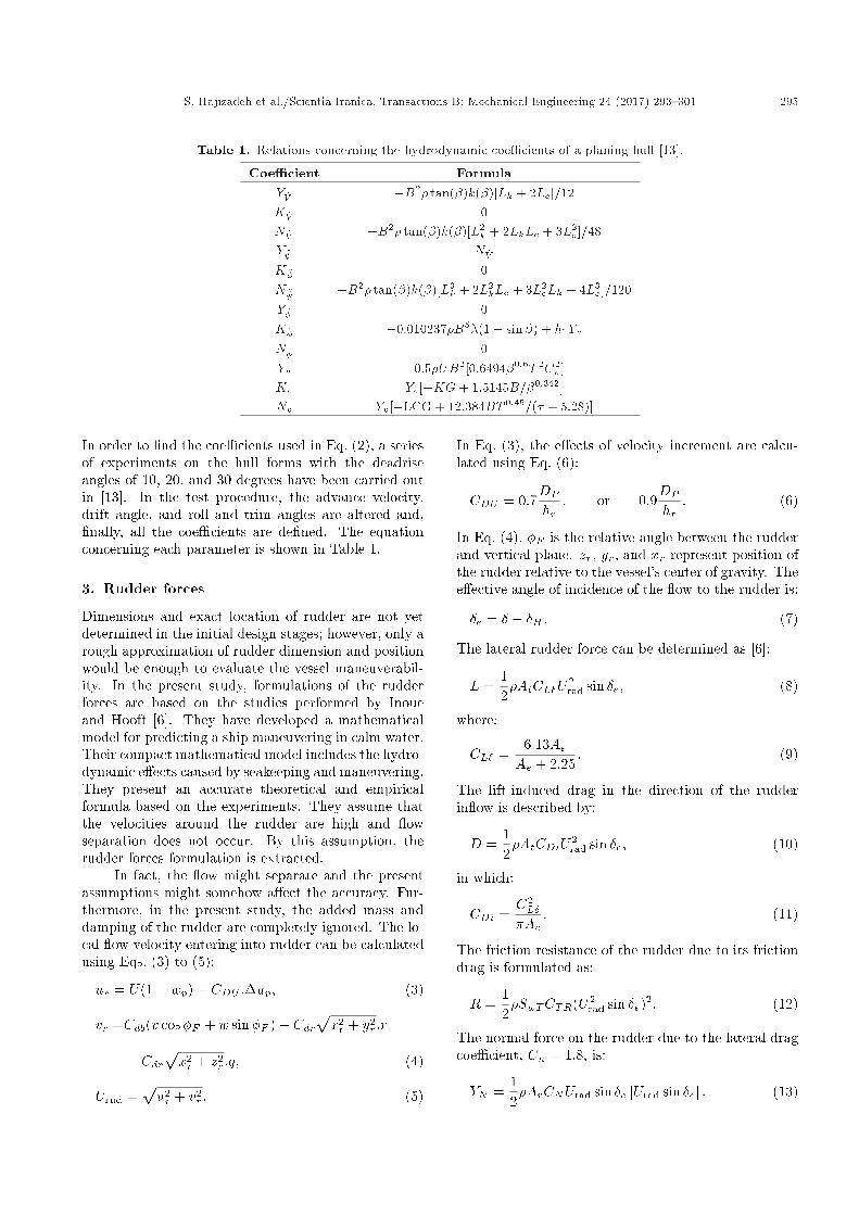
Table 1. Relations concerning the hydrodynamic coe�cients of a planing hull [13].
Coe�cient FormulaY _V �B2� tan(�)k(�)[Lk + 2Lc]=12K _V 0N _V �B2� tan(�)k(�)[L2
k + 2LkLc + 3L2c ]=48
Y � N _V
K � 0N � �B2� tan(�)k(�)[L3
k + 2L2kLc + 3L2
cLk + 4L3c ]=120
Y�� 0K�� �0:010237�B5�(1� sin�) + h1Y _v
N�� 0Yv �0:5�UB2[0:6494�0:6T 2C2
v ]Kv Yv[�KG+ 1:5145B=�0:342]Nv Yv[�LCG + 12:384BT 0:45=(� + 5:28)]
In order to �nd the coe�cients used in Eq. (2), a seriesof experiments on the hull forms with the deadriseangles of 10, 20, and 30 degrees have been carried outin [13]. In the test procedure, the advance velocity,drift angle, and roll and trim angles are altered and,�nally, all the coe�cients are de�ned. The equationconcerning each parameter is shown in Table 1.
3. Rudder forces
Dimensions and exact location of rudder are not yetdetermined in the initial design stages; however, only arough approximation of rudder dimension and positionwould be enough to evaluate the vessel maneuverabil-ity. In the present study, formulations of the rudderforces are based on the studies performed by Inoueand Hooft [6]. They have developed a mathematicalmodel for predicting a ship maneuvering in calm water.Their compact mathematical model includes the hydro-dynamic e�ects caused by seakeeping and maneuvering.They present an accurate theoretical and empiricalformula based on the experiments. They assume thatthe velocities around the rudder are high and owseparation does not occur. By this assumption, therudder forces formulation is extracted.
In fact, the ow might separate and the presentassumptions might somehow a�ect the accuracy. Fur-thermore, in the present study, the added mass anddamping of the rudder are completely ignored. The lo-cal ow velocity entering into rudder can be calculatedusing Eqs. (3) to (5):
ur = U(1� wp) + CDU :�up; (3)
vr =Cdb(v cos�F + w sin�F )� Cdrpx2r + y2
r :r
+ Cdrpx2r + z2
r :q; (4)
Urud =pu2r + v2
r : (5)
In Eq. (3), the e�ects of velocity increment are calcu-lated using Eq. (6):
CDU = 0:7DP
hr; or 0:9
DP
hr: (6)
In Eq. (4), �F is the relative angle between the rudderand vertical plane. zr, yr, and xr represent position ofthe rudder relative to the vessel's center of gravity. Thee�ective angle of incidence of the ow to the rudder is:
�e = � � �H : (7)
The lateral rudder force can be determined as [6]:
L =12�AtCL�U2
rad sin �e; (8)
where:
CL� =6:13AeAe + 2:25
: (9)
The lift-induced drag in the direction of the rudderin ow is described by:
D =12�AtCDiU2
rad sin �e; (10)
in which:
CDi =C2L�
�Ae: (11)
The friction resistance of the rudder due to its frictiondrag is formulated as:
R =12�SwTCTR(U2
rad sin �e)2: (12)
The normal force on the rudder due to the lateral dragcoe�cient, Cn = 1:8, is:
YN =12�ArCNUrad sin �e jUrad sin �ej : (13)
296 S. Hajizadeh et al./Scientia Iranica, Transactions B: Mechanical Engineering 24 (2017) 293{301
Therefore, following equations will de�ne the forces andmoments exerted on the rudder:Xrud = �R cos � �D cos �H � YN sin � � L sin �H ;
Yrud = (�R sin � �D sin �H + YN cos �
+ (1 + ah)L cos �H) cos�F ;
Zrud = (�R sin � �D sin �H + YN cos �
+ (1 + ah)L cos �H) sin�F ;
Mrud = Xrud:zr + Zrud:xr;
Nrud =�Xrud:yr+((YN cos ��R sin ��D sin �H):xr
+ (xr + ah:xh)L cos �H) cos�F : (14)
4. Model Speci�cations
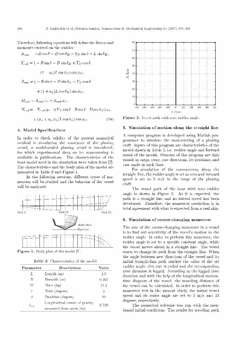
In order to check validity of the present numericalmethod in simulating the maneuver of the planingvessel, a model-scaled planing vessel is considered,for which experimental data on its maneuvering isavailable in publications. The characteristics of theboat model used in the simulation were taken from [7].The characteristics and the body plan of the model arepresented in Table 2 and Figure 1.
In the following sections, di�erent types of ma-neuvers will be studied and the behavior of the vesselwill be analyzed.
Figure 1. Body plan of the model [7].
Table 2. Characteristics of the model.
Parameter Description Value
L Length (m) 1.5B Breadth (m) 0.367M Mass (kg) 11.5� Trim (degree) 5� Deadrise (degree) 10
LcgLongitudinal center of gravitymeasured from stern (m)
0.726
Figure 2. Vessel path with zero rudder angle.
5. Simulation of motion along the straight line
A computer program is developed using Matlab pro-grammer to simulate the maneuvering of a planingcraft. Inputs of this program are characteristics of themodel shown in Table 2, i.e. rudder angle and forwardspeed of the model. Outputs of the program are shipspeeds in surge, sway, yaw directions, its positions, andyaw angle in each time.
For simulation of the maneuvering along thestraight line, the rudder angle is set to zero and forwardspeed is set to 5 m/s in the range of the planingcraft.
The vessel path of the boat with zero rudderangle is shown in Figure 2. As it is expected, thepath is a straight line and no lateral speed has beendeveloped. Therefore, the numerical prediction is intotal agreement with what is expected from a real ship.
6. Simulation of course-changing maneuver
The aim of the course-changing maneuver in a vesselis to �nd out sensitivity of the vessel's motion to therudder angle. In order to perform this maneuver, therudder angle is set to a speci�c constant angle, whilethe vessel moves ahead in a straight line. The vesselstarts to change its path from the straight line. Whenthe angle between new directions of the vessel and itsinitial straight-line path reaches the value of the setrudder angle, this test is ended and the correspondingtime duration is logged. According to the logged timeduration and with the help of the longitudinal motion-time diagram of the vessel, the traveling distance ofthe vessel can be calculated. In order to perform thismaneuver test in the present study, the initial vesselspeed and its ruder angle are set to 5 m/s and 15degrees, respectively.
The numerical software was run with the men-tioned initial conditions. The results for traveling path

S. Hajizadeh et al./Scientia Iranica, Transactions B: Mechanical Engineering 24 (2017) 293{301 297
of the vessel, vessel yaw diagram versus time, and thelongitudinal path traveled by the vessel versus timeare shown in Figures 3 to 5, respectively. In the yawdiagram of the vessel, the corresponding time thatthe yaw angle of the vessel took to reach 15 degreeswas logged. Then, using the longitudinal displacementdiagram of the vessel along the surge motion, itstraveled distance was determined. This procedure wasrepeated for the negative angle of the rudder, whichhad the same result.
As seen in Figure 4, when the rudder angle is setto 15 degrees, it takes 2.7 seconds for yaw angle of thevessel to reach 15 degrees. In this time duration, thevessel travels about 15 times its own length accordingto Figure 5. The displacement along the surge directionlooks linear, but it is not true linear. Its rate incrementdecreases as the vessel approaches 90 degrees. Thistraveled path can be compared to those of the designguidelines, if any exists.
Figure 3. Vessel traveling path corresponding to therudder angle of 15 degrees.
Figure 4. Vessel yaw angle corresponding to the rudderangle of 15 degrees.
7. Simulation of the turning circle maneuver
In some situations (like collision avoidance), it isnecessary for a vessel to turn while keeping stability inthe maneuvering. According to Figure 6, in the turningcircle maneuver, at �rst, the vessel travels in a straightline with a constant speed and, then, the rudder angleis set to its maximum and kept �xed until the vesseltravels a whole circle (at least 540 degrees). This testshould be performed for both portside and starboardsides of the vessel.
For simulation of the turning test, it was consid-
Figure 5. Vessel displacement along the surge motionwith the rudder angle of 15 degrees.
Figure 6. De�nitions used in turning test [14].
298 S. Hajizadeh et al./Scientia Iranica, Transactions B: Mechanical Engineering 24 (2017) 293{301
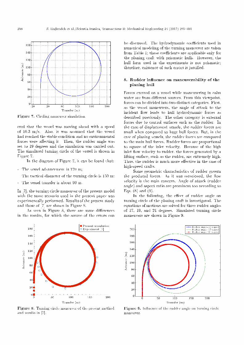
Figure 7. Circling maneuver simulation.
ered that the vessel was moving ahead with a speedof 10.3 m/s. Also, it was assumed that the vesselhad reached the stable condition and no environmentalforces were a�ecting it. Then, the rudder angle wasset to 19 degrees and the simulation was carried out.The simulated turning circle of the vessel is shown inFigure 7.
In the diagram of Figure 7, it can be found that:
- The vessel advancement is 170 m;
- The tactical diameter of the turning circle is 150 m;
- The vessel transfer is about 90 m.
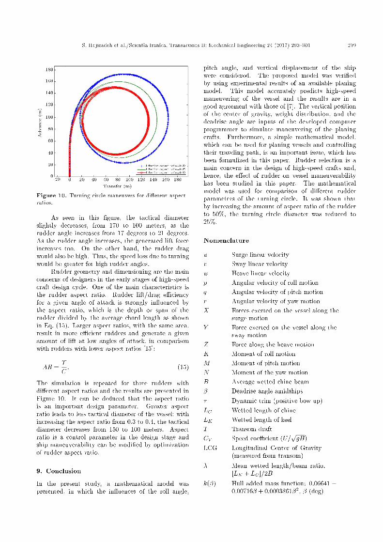
In [7], the turning circle maneuver of the present modelwith the same scenario used in the present paper wasexperimentally performed. Results of the present studyand those of [7] are shown in Figure 8.
As seen in Figure 8, there are some di�erencesin the results, for which the source of the errors can
Figure 8. Turning circle maneuver of the present methodand results in [7].
be discussed. The hydrodynamic coe�cients used innumerical modeling of the turning maneuver are takenfrom Table 1; these coe�cients are applicable only forthe planing craft with prismatic hulls. However, thehull form used in the experiments is not prismatic;therefore, existence of such errors is justi�ed.
8. Rudder in uence on maneuverability of theplaning hull
Forces exerted on a vessel while maneuvering in calmwater are from di�erent sources. From this viewpoint,forces can be divided into two distinct categories. First,as the vessel maneuvers, the angle of attack to theincident ow leads to hull hydrodynamic forces asdescribed previously. The other category is externalforces due to control surfaces such as the rudder. Inthe case of displacement vessels, the rudder forces aresmall when compared to huge hull forces. But, in thecase of planing vessels, the rudder forces are comparedto the main hull forces. Rudder forces are proportionalto square of the inlet velocity. Because of the highinlet ow velocity to rudder, the forces generated by alifting surface, such as the rudder, are extremely high.Thus, the rudder is much more e�ective in the case ofhigh-speed crafts.
Some geometric characteristics of rudder governthe produced forces. As it was mentioned, the owvelocity is the main concern. Angle of attack (rudderangle) and aspect ratio are prominent too according toEqs. (8) and (9).
In the following, the e�ect of rudder angle onturning circle of the planing craft is investigated. Theequations of motions are solved for three rudder anglesof 17, 19, and 21 degrees. Simulated turning circlemaneuvers are shown in Figure 9.
Figure 9. In uence of the rudder angle on turning circlemaneuver.
S. Hajizadeh et al./Scientia Iranica, Transactions B: Mechanical Engineering 24 (2017) 293{301 299
Figure 10. Turning circle maneuvers for di�erent aspectratios.
As seen in this �gure, the tactical diameterslightly decreases, from 170 to 100 meters, as therudder angle increases from 17 degrees to 21 degrees.As the rudder angle increases, the generated lift forceincreases too. On the other hand, the rudder dragwould also be high. Thus, the speed loss due to turningwould be greater for high rudder angles.
Rudder geometry and dimensioning are the mainconcerns of designers in the early stages of high-speedcraft design cycle. One of the main characteristics isthe rudder aspect ratio. Rudder lift/drag e�ciencyfor a given angle of attack is strongly in uenced bythe aspect ratio, which is the depth or span of therudder divided by the average chord length as shownin Eq. (15). Larger aspect ratios, with the same area,result in more e�cient rudders and generate a givenamount of lift at low angles of attack, in comparisonwith rudders with lower aspect ratios [15]:
AR =TC: (15)
The simulation is repeated for three rudders withdi�erent aspect ratios and the results are presented inFigure 10. It can be deduced that the aspect ratiois an important design parameter. Greater aspectratio leads to less tactical diameter of the vessel; withincreasing the aspect ratio from 0.3 to 0.4, the tacticaldiameter decreases from 150 to 100 meters. Aspectratio is a control parameter in the design stage andship maneuverability can be modi�ed by optimizationof rudder aspect ratio.
9. Conclusion
In the present study, a mathematical model waspresented, in which the in uences of the roll angle,
pitch angle, and vertical displacement of the shipwere considered. The proposed model was veri�edby using experimental results of an available planingmodel. This model accurately predicts high-speedmaneuvering of the vessel and the results are in agood agreement with those of [7]. The vertical positionof the center of gravity, weight distribution, and thedeadrise angle are inputs of the developed computerprogrammer to simulate maneuvering of the planingcrafts. Furthermore, a simple mathematical model,which can be used for planing vessels and controllingtheir traveling path, is an important issue, which hasbeen formulized in this paper. Rudder selection is amain concern in the design of high-speed crafts and,hence, the e�ect of rudder on vessel maneuverabilityhas been studied in this paper. The mathematicalmodel was used for comparison of di�erent rudderparameters of the turning circle. It was shown thatby increasing the amount of aspect ratio of the rudderto 50%, the turning circle diameter was reduced to25%.
Nomenclature
u Surge linear velocityv Sway linear velocityw Heave linear velocityp Angular velocity of roll motionq Angular velocity of pitch motionr Angular velocity of yaw motionX Forces exerted on the vessel along the
surge motionY Force exerted on the vessel along the
sway motionZ Force along the heave motionK Moment of roll motionM Moment of pitch motionN Moment of the yaw motionB Average wetted chine beam� Deadrise angle amidships� Dynamic trim (positive bow up)LC Wetted length of chineLK Wetted length of keelT Transom draftCV Speed coe�cient (U=
pgB)
LCG Longitudinal Center of Gravity(measured from transom)
� Mean wetted length/beam ratio,[LK + LC ]=2B
k(�) Hull added mass function: 0:06641 +0:00716� + 0:0003861�2, � (deg)

300 S. Hajizadeh et al./Scientia Iranica, Transactions B: Mechanical Engineering 24 (2017) 293{301
KG Height of the CG from the keelI Moment inertiam Ship mass�e E�ective angle of incidence of the ow
to the rudder� Rudder angleL Lateral rudder forceshr Rudder heightcr Rudder cord lengthAr Rudder lateral surfaceAe E�ective aspect ratio of rudder
References
1. Ye. Li, \The simulation of ship maneuvering &course keeping with escort tus", M.S. Thesis, Depart-ment of mechanical engineering, University of BritishColumbia, pp. 13-60 (2004).
2. ITTC Recommended Procedures & Guidelines, Testingand Extrapolation Methods Manoeuvrability Free Run-ning Model Tests, pp. 1-10 (2005).
3. Fossen, T.I. \A nonlinear uni�ed state-space model forship maneuvering & control in a seaway", Journal ofBifurcation and Chaos, pp. 1-28 (2005).
4. Suhrbier, K.R. \An experimental investigation on theroll stability of a semi-displacement craft at forwardspeed", Symposium on Small Fast Warship and Secu-rity Vessels, The Royal Institution of Naval Architects,Paper No. 9, pp. 133-142 (1978).
5. Deakin, B. \Model tests to assess the manoeuvring ofplaning craft", The International HISWA Symposiumon Yacht Design and Yacht Construction, pp. 21-32(2005).
6. Toxopeus, S.L. Keuning, J.A. and Hooft, J.P. \Dy-namic stability of planing ships", International Sym-posium and Seminar on the Safety of High Speed Craft,London, UK, pp. 1-16 (1997).
7. Plante, M., Toxopeus, S., Blok, J. and Keuning,A. \Hydrodynamic maneuvering aspects of planingcraft", International Symposium and Workshop onForces Acting on a Manoeuvring Vessel, Val de Reuil,FranceV, pp. 1-9 (1998).
8. Katayama, T., Taniguchi, T., Fujii, H. and Ikeda, Y.\Development of maneuvering simulation method forhigh speed craft using hydrodynamic forces obtainedfrom model tests", 10th International Conference onFast Sea Transportation FAST 2009, Athens, Greece,pp. 477-489 (2009).
9. Javanmardi, M.R., Seif, M.S., Jahanbakhsh, E.and Sayyaadi, H. \Trimaran maneuvering simulation,based on a three-dimensional viscous free surface owsolver", Proceeding of 6th International Conference
on High-Performance Marine Vehicles (HIPER'08),Naples, pp. 249-256 (2008).
10. Jahanbakhsh, E., Panahi, R. and Seif, M.S. \Cata-maran motion simulation based on moving grid tech-nique", Journal of Marine Science and Technology,17(2), pp. 128-136 (2009).
11. Araki, M., Sadat-Hosseini, H., Sanda, Y., Tanimoto,K. and Umeda, N. \Estimating maneuvering coe�-cients using system identi�cation methods with ex-perimental", System-Based, and CFD Free-runningTrial Data, Ocean Engineering Journal, 51, pp. 63-84(2012).
12. Simonsen, C.D., Otzen, J.F., Klimt, C. and Larsen,N.L. \Maneuvering predictions in the early designphase using CFD generated PMM data", 29th Sympo-sium on Naval Hydrodynamics, Gothenburg, Sweden,pp. 26-31 (2012).
13. Lewandowski, E.M. \The dynamics of marine craft:maneuvering and seakeeping", Advanced Series onOcean Engineering, 22, Copyright 2004 by WorldScienti�c Publishing Co. Pte. Ltd, pp. 50-120 (2004).
14. Bertram, V., Practical Ship Hydrodynamics, BritishLibrary Cataloguing in Publication Data, First pub-lished, pp. 150-200 (2000)
15. Patton, M.R. \Evaluation of dynamic lift coe�cientsof high aspect ratio rudders and control surfaces",United States Naval Academy Annapolis, Maryland,U.S.N.A. Trident Scholar project report; pp. 1-134(2004).
Biographies
Sajad Hajizadeh received the BSc degree in NavalArchitecture from Persian Gulf University, Busher,Iran, in 2007 and the MSc degree in Marine Engi-neering from Sharif University of Technology, Tehran,Iran, in 2010. He is currently PhD student in theSchool of Mechanical Engineering at Sharif Universityof Technology, Tehran, Iran. His main areas ofinterest are hydrodynamic and maneuvering of marinevehicles. He has published several papers in this�eld.
Mohammad Saeed Seif received the BSc degree inMechanical Engineering from Amirkabir University ofTechnology, Tehran, Iran, in 1989; the MSc degreein Naval Architecture from Technical University ofGdansk, Gdansk, Poland, in 1992; and PhD degreein Mechanical Engineering from Yokohama NationalUniversity, Yokohama, Japan, in 1995. He is cur-rently Professor in the Department of MechanicalEngineering, Sharif University of Technology, Tehran,Iran. His area of expertise is dynamics and hydrody-namics of marine vehicles, ship structure design, ad-vanced marine vehicles, and advanced uid dynamics.

S. Hajizadeh et al./Scientia Iranica, Transactions B: Mechanical Engineering 24 (2017) 293{301 301
He has published several papers in the maneuvering�eld.
Hamid Mehdigholi received the BSc degree in Me-chanical Engineering from Sharif University of Tech-nology, Tehran, Iran, in 1977 and the MS and PhD
degrees in Applied Mechanics from Imperial College,London, in 1986 and 1991, respectively. He has beena Faculty Member at Sharif University of Technologysince 1991. His research interests include dynamics ofrotating machines, vibration isolation, acoustics, andexperimental modal analysis.


![Effect of Engine Output on Maneuverability of a VLCC in ...tioned the engine output effect on the ship maneuverability in adverse weather conditions. Takahashi and Asai [8] investigated](https://img.pdfslide.us/doc/110x75/5e9756f1e2744c16fc4955fb/effect-of-engine-output-on-maneuverability-of-a-vlcc-in-tioned-the-engine-output.jpg)