Embed Size (px)
Citation preview
International Journal of Applied Engineering Research ISSN 0973-4562 Volume 13, Number 10 (2018) pp. 7348-7359
© Research India Publications. http://www.ripublication.com
7348
Evaluation of Noise Insulation Performance for Void Deck Slab System
which Combines Deck Plates with a Voided Slab System
In-Kwan Paik 1, and Seunguk Na 2*
1Department of architectural engineering, School of Architecture, Dankook University, South Korea.
2Department of architectural engineering, School of Architecture, Dankook University, South Korea.
(*Correspondence Author)
Abstract
A voided slab system is one of the newly developed methods
used to improve the load resistance by effectively utilising the
moment of inertia in a concrete slab. It has several advantages
such as economic efficiency, usability, and environmental
friendliness. In this study, the authors developed a new voided
slab system, called a void deck slab (VDS) system, which is
combined with voided slab systems and deck plates. The
purpose of this study is to investigate the sound insulation
performance of VDS. To determine its effectiveness, a mock
up test was carried out to evaluate its insulation performance
against floor impact noise and its applicability to a voided slab
system. The test results show that the light impact sound
insulation performance reached grade 1, and the heavy impact
sound insulation performance reached grade 3. These results
satisfy the required impact sound insulation performance of
apartment housing. Based on these results, it is expected that
the application of VDS can be useful in preventing interlayer
noise issues in apartment housing in South Korea. In addition,
it is thought that a reduction of in the quantity of concrete
required will not only improve the workability in construction
sites, it will also reduce the emissions of carbon dioxide. Thus,
VDS will be a useful alternative method to improving the
habitability for occupants and the workability for workers at
construction sites.
Keywords: voided slab; deck plate; noise insulation
performance; interlayer noise issue; apartment housing; light
impact noise
INTRODUCTION
A voided slab system is one of the newly developed methods
used to improve the load resistance by effectively utilising the
moment of inertia in a concrete slab. It has several advantages
such as economic efficiency, usability, and environmental
friendliness. In contrast, it also has certain disadvantages in that
construction difficulties on site are higher than with normal
reinforced concrete slabs despite the decrease in the quantity of
concrete and reinforcing bars. In addition, the economic
efficiency is worse in that extra construction costs are incurred
when the voided part is not properly constructed. To overcome
such difficulties of a voided slab, a number of new methods
have been developed.
Voided slab systems have been actively applied to buildings
and are being continuously used in many countries including
those in Europe, Asia, North America, the Middle East, and
Oceania. In particular, it has been proven that a voided slab
system is beneficial in lowering the noise propagation and noise
complaints between floors in apartment housing in Japan. In
South Korea, voided slab systems with steel pipes have been
applied to the Grand Hyatt hotel and several different
warehouses. The system has since been gradually applied to
large buildings and long-span structures such as underground
parking structures, office buildings, factories, cinemas, and
religious facilities. In addition, it is being investigated whether
the utilisation of a voided slab system can solve social issues
such as noise complaints and floor impact noises caused by
footsteps in apartment housing, which occupies the majority of
domestic dwelling types.
Noise insulation from indoor and outdoor-generated noises in
apartments is a significant factor in improving the quality of
life and comfort of residents. One of the most frequently
generated noise issues amongst occupants in apartment housing
in South Korea is noise complaints that occur between upstairs
and downstairs neighbours (i.e., interlayer noise problems).
Because such noise complaints have become a serious social
issue, a number of efforts and technologies have been proposed
to resolve the problem. Interlayer noise is a type of floor impact
noise, and is the most important aspect of residents of
apartment dwellings in evaluating the comfort and indoor noise
level. To reduce the interlayer noise problem, it is necessary to
assess the level of impact of sound insulation from slabs
applied in a building structure. It has been reported that the
former materials used in voided slabs have an outstanding
performance in terms of sound insulation against floor impact
sounds. In this study, the authors developed a new voided slab
system, called a void deck slab (VDS) system, which is
combined with voided slab systems and deck plates. The
purpose of this study is to investigate the sound insulation
performance of VDS. To determine its effectiveness, a mock
up test was carried out to evaluate its insulation performance
against floor impact noise and its applicability to a voided slab
system.
International Journal of Applied Engineering Research ISSN 0973-4562 Volume 13, Number 10 (2018) pp. 7348-7359
© Research India Publications. http://www.ripublication.com
7349
LITERATURE REVIEW
Voided slab or hollow core slab systems have been used for
many years in the field of civil engineering in South Korea,
where long span structures such as bridges and dams are
frequently constructed. However, the application of voided slab
systems in the architectural, engineering, and construction
(AEC) industry occurred later in South Korea than in Europe
or Japan. Although it is late compared to other countries, the
design and construction of voided slab systems are now being
carried out in the construction of various long-span buildings
and large facilities in the AEC industry.
Research into voided slab systems in South Korea has focused
on the development of anchoring methods and the shape of the
void former materials. Various studies have proposed the use
of new materials to anchor the void former materials into
concrete slabs. The majority of studies regarding anchoring
materials have focused on the use of reinforcing bars, which fix
the anchoring materials to the lower reinforcement of the slab.
The reasons for using anchoring materials have been to prevent
buoyancy, which occurs during the placement and curing of
concrete, as well as the movement of void former materials by
workers during reinforcement tasks. Another research theme
regarding voided slabs has been the development of new shapes
of void former materials. The most significant factors in
researching the shapes of void former materials has been
attaining an optimal hollowness ratio that is able to distribute
stress and demonstrating the best structural performance of
voided slabs. Research on voided slabs in South Korea is
summarised in Table 1.
A considerable amount of research into voided slabs has been
studied and accumulated in Europe and Japan since the 1900s.
In particular, a voided slab system has been proven to
significantly reduce the interlayer and impact noises occurring
in apartment dwellings, and has therefore been widely used in
apartment houses in Japan. The main research trends toward the
use of voided slabs in foreign countries have been similar to the
topics in South Korea, which are the development of anchoring
materials, and finding the optimal hollowness ratio. Such
research trends can be confirmed through the number of patent
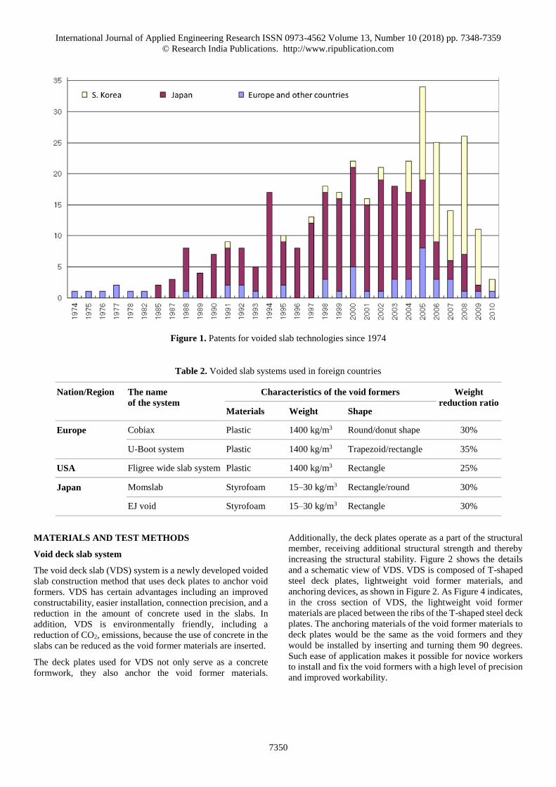
applications and registrations (see Figure 1). As shown in
Figure 1, the development of voided slabs has been progressing
in Europe since 1974, and patent applications and registrations
were continuously submitted between the mid-1980s to the
mid- 2000s in Japan. In the case of South Korea, the
development of voided slab systems has rapidly increased since
the mid-2000s. BubbleDeck Technology in Denmark and
Cobiax Technologies AG in Switzerland have developed a
voided slab system that lowers the amount of concrete required
and therefore the weight of the slab by using spherical or
elliptical plastic balls as lightweight void former materials for
application in one- and two-way slabs. The main feature of
Cobiax Technologies AG is to develop cages for fixing
spherical or elliptical lightweight void formers to reinforcing
bars to slabs. As a Japanese study, while Sekisui Plastics Co.,
Ltd., focused on the development of voided slabs using half
precast concrete in the 1980s, in recent years the company has
been researching new technologies to prevent the detachment
or separation of void formers from slabs. Moreover, various
other companies in Japan such as Kurimoto, Penta Ocean, and
Shimizu are trying to develop new materials to fix or anchor
void former materials to a slab to secure their reliability and
durability. Table 2 summarises recently proposed technologies
and materials used in voided slabs in foreign countries and
regions.
Table 1. Research on voided slabs in South Korea
Authors Year Title
Chung et al. 2009 An analytical study of hollow slabs with optimal hollow spherical shapes
Kim et al. 2009 Structural performance tests of two-way void slabs
Joo et al. 2011 Structural performance test on installation method of void former for void slab using deck plate
Lee et al. 2011 Experimental evaluation on punching shear of two-way void slab-to-column connection with
TVS lightweight ball
Chung et al. 2013 Experimental study on the bond characteristics of deformed bar embedded in donut type biaxial
hollow slab
International Journal of Applied Engineering Research ISSN 0973-4562 Volume 13, Number 10 (2018) pp. 7348-7359
© Research India Publications. http://www.ripublication.com
7350
Figure 1. Patents for voided slab technologies since 1974
Table 2. Voided slab systems used in foreign countries
Nation/Region The name
of the system
Characteristics of the void formers Weight
reduction ratio Materials Weight Shape
Europe Cobiax Plastic 1400 kg/m3 Round/donut shape 30%
U-Boot system Plastic 1400 kg/m3 Trapezoid/rectangle 35%
USA Fligree wide slab system Plastic 1400 kg/m3 Rectangle 25%
Japan Momslab Styrofoam 15–30 kg/m3 Rectangle/round 30%
EJ void Styrofoam 15–30 kg/m3 Rectangle 30%
MATERIALS AND TEST METHODS
Void deck slab system
The void deck slab (VDS) system is a newly developed voided
slab construction method that uses deck plates to anchor void
formers. VDS has certain advantages including an improved
constructability, easier installation, connection precision, and a
reduction in the amount of concrete used in the slabs. In
addition, VDS is environmentally friendly, including a
reduction of CO2, emissions, because the use of concrete in the
slabs can be reduced as the void former materials are inserted.
The deck plates used for VDS not only serve as a concrete
formwork, they also anchor the void former materials.
Additionally, the deck plates operate as a part of the structural
member, receiving additional structural strength and thereby
increasing the structural stability. Figure 2 shows the details
and a schematic view of VDS. VDS is composed of T-shaped
steel deck plates, lightweight void former materials, and
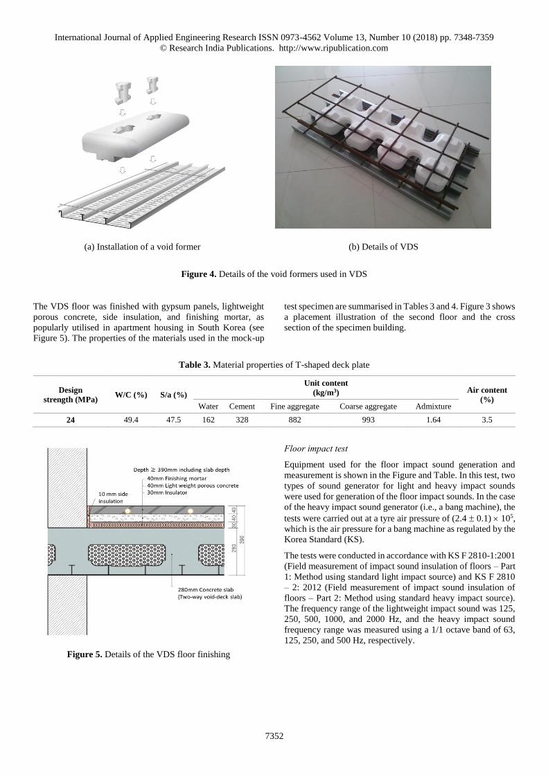
anchoring devices, as shown in Figure 2. As Figure 4 indicates,
in the cross section of VDS, the lightweight void former
materials are placed between the ribs of the T-shaped steel deck
plates. The anchoring materials of the void former materials to
deck plates would be the same as the void formers and they
would be installed by inserting and turning them 90 degrees.
Such ease of application makes it possible for novice workers
to install and fix the void formers with a high level of precision
and improved workability.
International Journal of Applied Engineering Research ISSN 0973-4562 Volume 13, Number 10 (2018) pp. 7348-7359
© Research India Publications. http://www.ripublication.com
7351
(a) Schematic view of VDS (b) Details of VDS
Figure 2. Conceptual diagram and details of void deck slab (VDS) system
Test overview
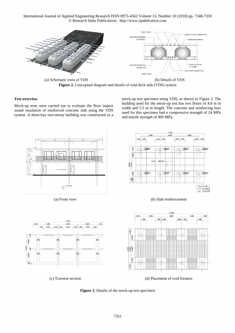
Mock-up tests were carried out to evaluate the floor impact
sound insulation of reinforced concrete slab using the VDS
system. A three-bay two-storey building was constructed as a
mock-up test specimen using VDS, as shown in Figure 3. The
building used for the mock-up test has two floors of 4.8 m in
width and 5.5 m in length. The concrete and reinforcing bars
used for this specimen had a compressive strength of 24 MPa
and tensile strength of 400 MPa.
(a) Front view (b) Slab reinforcement
(c) Traverse section (d) Placement of void formers
Figure 3. Details of the mock-up test specimen
International Journal of Applied Engineering Research ISSN 0973-4562 Volume 13, Number 10 (2018) pp. 7348-7359
© Research India Publications. http://www.ripublication.com
7352
(a) Installation of a void former (b) Details of VDS
Figure 4. Details of the void formers used in VDS
The VDS floor was finished with gypsum panels, lightweight
porous concrete, side insulation, and finishing mortar, as
popularly utilised in apartment housing in South Korea (see
Figure 5). The properties of the materials used in the mock-up
test specimen are summarised in Tables 3 and 4. Figure 3 shows
a placement illustration of the second floor and the cross
section of the specimen building.
Table 3. Material properties of T-shaped deck plate
Design
strength (MPa) W/C (%) S/a (%)
Unit content
(kg/m3) Air content
(%) Water Cement Fine aggregate Coarse aggregate Admixture
24 49.4 47.5 162 328 882 993 1.64 3.5
Figure 5. Details of the VDS floor finishing
Floor impact test
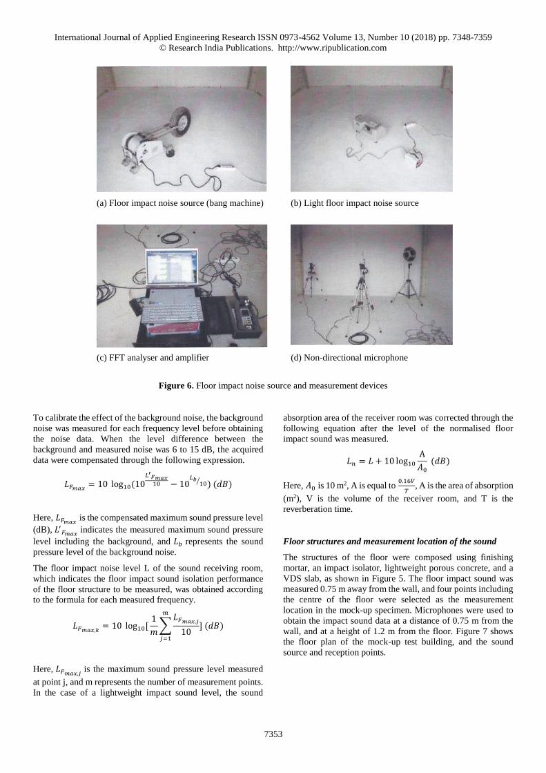
Equipment used for the floor impact sound generation and
measurement is shown in the Figure and Table. In this test, two
types of sound generator for light and heavy impact sounds
were used for generation of the floor impact sounds. In the case
of the heavy impact sound generator (i.e., a bang machine), the
tests were carried out at a tyre air pressure of (2.4 0.1) 105,
which is the air pressure for a bang machine as regulated by the
Korea Standard (KS).
The tests were conducted in accordance with KS F 2810-1:2001
(Field measurement of impact sound insulation of floors – Part
1: Method using standard light impact source) and KS F 2810
– 2: 2012 (Field measurement of impact sound insulation of
floors – Part 2: Method using standard heavy impact source).
The frequency range of the lightweight impact sound was 125,
250, 500, 1000, and 2000 Hz, and the heavy impact sound
frequency range was measured using a 1/1 octave band of 63,
125, 250, and 500 Hz, respectively.
International Journal of Applied Engineering Research ISSN 0973-4562 Volume 13, Number 10 (2018) pp. 7348-7359
© Research India Publications. http://www.ripublication.com
7353
(a) Floor impact noise source (bang machine) (b) Light floor impact noise source
(c) FFT analyser and amplifier (d) Non-directional microphone
Figure 6. Floor impact noise source and measurement devices
To calibrate the effect of the background noise, the background
noise was measured for each frequency level before obtaining
the noise data. When the level difference between the
background and measured noise was 6 to 15 dB, the acquired
data were compensated through the following expression.
𝐿𝐹𝑚𝑎𝑥= 10 log10(10
𝐿′𝐹𝑚𝑎𝑥10 − 10
𝐿𝑏10⁄ ) (𝑑𝐵)
Here, 𝐿𝐹𝑚𝑎𝑥 is the compensated maximum sound pressure level
(dB), 𝐿′𝐹𝑚𝑎𝑥
indicates the measured maximum sound pressure
level including the background, and 𝐿𝑏 represents the sound
pressure level of the background noise.
The floor impact noise level L of the sound receiving room,
which indicates the floor impact sound isolation performance
of the floor structure to be measured, was obtained according
to the formula for each measured frequency.
𝐿𝐹𝑚𝑎𝑥,𝑘= 10 log10[
1
𝑚∑
𝐿𝐹𝑚𝑎𝑥,𝑗
10
𝑚
𝑗=1
] (𝑑𝐵)
Here, 𝐿𝐹𝑚𝑎𝑥,𝑗 is the maximum sound pressure level measured
at point j, and m represents the number of measurement points.
In the case of a lightweight impact sound level, the sound
absorption area of the receiver room was corrected through the
following equation after the level of the normalised floor
impact sound was measured.
𝐿𝑛 = 𝐿 + 10 log10
A
𝐴0
(𝑑𝐵)
Here, 𝐴0 is 10 m2, A is equal to 0.16𝑉
𝑇, A is the area of absorption
(m2), V is the volume of the receiver room, and T is the
reverberation time.
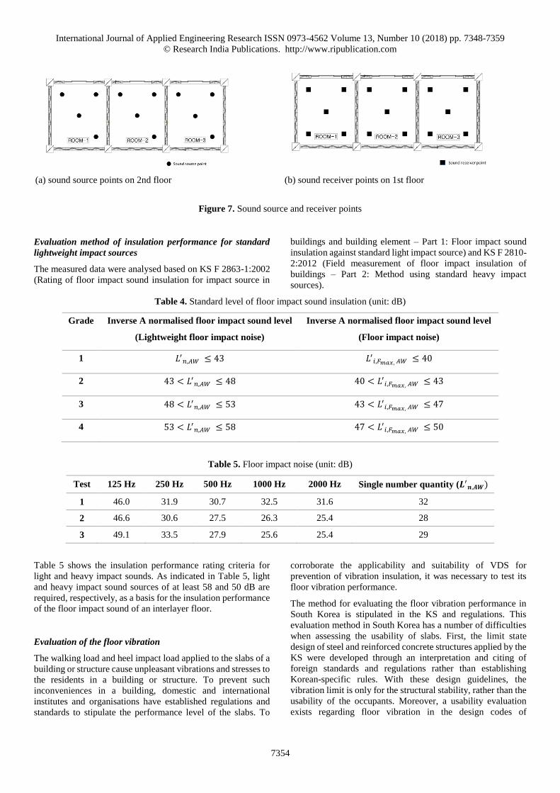
Floor structures and measurement location of the sound
The structures of the floor were composed using finishing
mortar, an impact isolator, lightweight porous concrete, and a
VDS slab, as shown in Figure 5. The floor impact sound was
measured 0.75 m away from the wall, and four points including
the centre of the floor were selected as the measurement
location in the mock-up specimen. Microphones were used to
obtain the impact sound data at a distance of 0.75 m from the
wall, and at a height of 1.2 m from the floor. Figure 7 shows
the floor plan of the mock-up test building, and the sound
source and reception points.
International Journal of Applied Engineering Research ISSN 0973-4562 Volume 13, Number 10 (2018) pp. 7348-7359
© Research India Publications. http://www.ripublication.com
7354
(a) sound source points on 2nd floor (b) sound receiver points on 1st floor
Figure 7. Sound source and receiver points
Evaluation method of insulation performance for standard
lightweight impact sources
The measured data were analysed based on KS F 2863-1:2002
(Rating of floor impact sound insulation for impact source in
buildings and building element – Part 1: Floor impact sound
insulation against standard light impact source) and KS F 2810-
2:2012 (Field measurement of floor impact insulation of
buildings – Part 2: Method using standard heavy impact
sources).
Table 4. Standard level of floor impact sound insulation (unit: dB)
Grade Inverse A normalised floor impact sound level
(Lightweight floor impact noise)
Inverse A normalised floor impact sound level
(Floor impact noise)
1 𝐿′𝑛,𝐴𝑊 ≤ 43 𝐿′
𝑖,𝐹𝑚𝑎𝑥, 𝐴𝑊 ≤ 40
2 43 < 𝐿′𝑛,𝐴𝑊 ≤ 48 40 < 𝐿′
𝑖,𝐹𝑚𝑎𝑥, 𝐴𝑊 ≤ 43
3 48 < 𝐿′𝑛,𝐴𝑊 ≤ 53 43 < 𝐿′
𝑖,𝐹𝑚𝑎𝑥, 𝐴𝑊 ≤ 47
4 53 < 𝐿′𝑛,𝐴𝑊 ≤ 58 47 < 𝐿′
𝑖,𝐹𝑚𝑎𝑥, 𝐴𝑊 ≤ 50
Table 5. Floor impact noise (unit: dB)
Test 125 Hz 250 Hz 500 Hz 1000 Hz 2000 Hz Single number quantity (𝑳′𝒏,𝑨𝑾)
1 46.0 31.9 30.7 32.5 31.6 32
2 46.6 30.6 27.5 26.3 25.4 28
3 49.1 33.5 27.9 25.6 25.4 29
Table 5 shows the insulation performance rating criteria for
light and heavy impact sounds. As indicated in Table 5, light
and heavy impact sound sources of at least 58 and 50 dB are
required, respectively, as a basis for the insulation performance
of the floor impact sound of an interlayer floor.
Evaluation of the floor vibration
The walking load and heel impact load applied to the slabs of a
building or structure cause unpleasant vibrations and stresses to
the residents in a building or structure. To prevent such
inconveniences in a building, domestic and international
institutes and organisations have established regulations and
standards to stipulate the performance level of the slabs. To
corroborate the applicability and suitability of VDS for
prevention of vibration insulation, it was necessary to test its
floor vibration performance.
The method for evaluating the floor vibration performance in
South Korea is stipulated in the KS and regulations. This
evaluation method in South Korea has a number of difficulties
when assessing the usability of slabs. First, the limit state
design of steel and reinforced concrete structures applied by the
KS were developed through an interpretation and citing of
foreign standards and regulations rather than establishing
Korean-specific rules. With these design guidelines, the
vibration limit is only for the structural stability, rather than the
usability of the occupants. Moreover, a usability evaluation
exists regarding floor vibration in the design codes of
International Journal of Applied Engineering Research ISSN 0973-4562 Volume 13, Number 10 (2018) pp. 7348-7359
© Research India Publications. http://www.ripublication.com
7355
composite slabs with a deck plate, and in the design
specifications for cold-formed steel sections. However, the
evaluation methods in these criteria limit the minimum natural
frequency of the slabs, and thus it might be difficult to evaluate
the usability in terms of the occupants or users being able to
feel vibrations. Lastly, the Noise and Vibration Control Act in
South Korea measures the damage level of a building or
structure by defining the horizontal limits regardless of the
frequency bands rather than an evaluation of the usability of the
residents in the building.
On the other hand, the evaluation method of the vibration
performance in other countries is divided into two evaluation
criteria. The first is an evaluation method using an allowable
limit of natural frequency. This method uses the modified
Reiher-Meister curve, which applies the average value obtained
from experience and actual experiments. The other is evaluated
using the natural frequencies, damping ratios, and limit
accelerations using evaluation or empirical formulas. In
particular, ISO 2631-2 (1989), “Guidelines for evaluating
residential performance on vibration of buildings,” by the
Architectural Institute of Japan (AIJ), and DIN 4150-3 (1999)
are guidelines for evaluating the direct habitability in which the
residents will feel floor vibrations. In this study, the evaluation
method proposed by AIJ was adopted to examine the usability
and habitability of VDS.
The AIJ method for evaluating floor vibrations is based on
analysing various standards such as ISO 2631-2, Reiher-
Meister, GSA, and CSA, and a response curve in accordance
with the Japanese design criteria was proposed. To assess the
vibration using this evaluation method, the performance
evaluation curves are divided into impact vibrations and
continuous vibrations. To meet the criteria, the applied
vibration is separated into heel drop and walking loads.
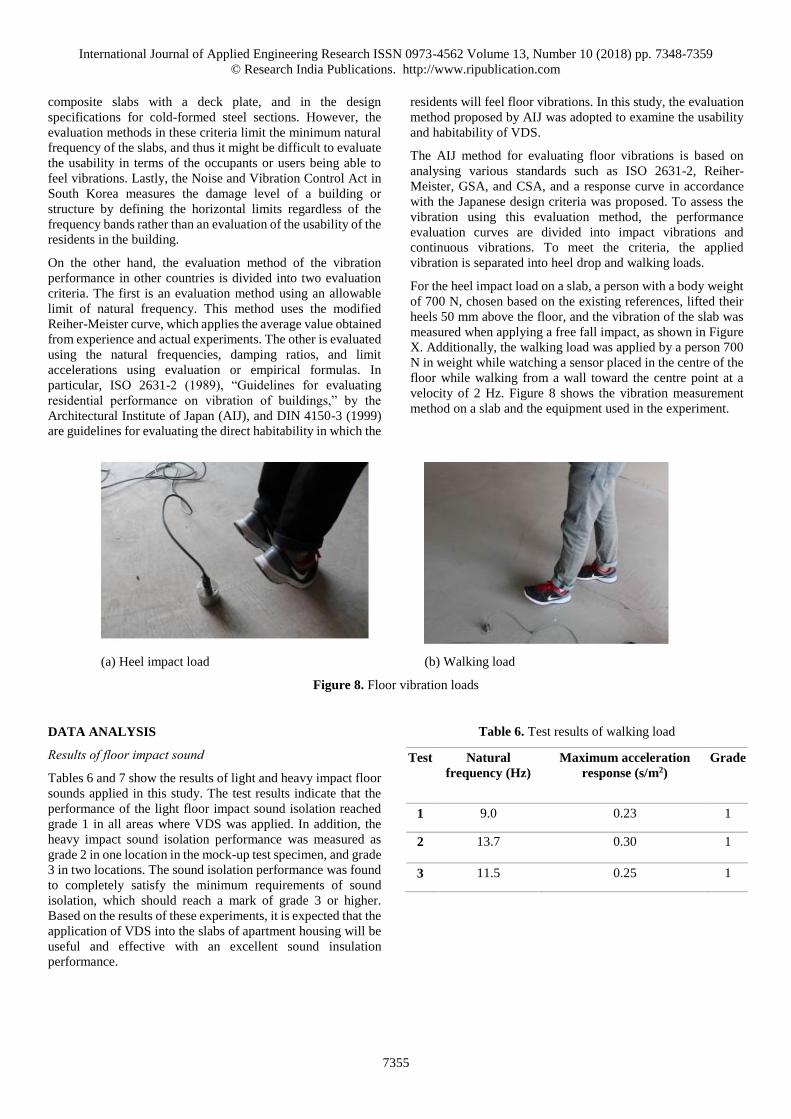
For the heel impact load on a slab, a person with a body weight
of 700 N, chosen based on the existing references, lifted their
heels 50 mm above the floor, and the vibration of the slab was
measured when applying a free fall impact, as shown in Figure
X. Additionally, the walking load was applied by a person 700
N in weight while watching a sensor placed in the centre of the
floor while walking from a wall toward the centre point at a
velocity of 2 Hz. Figure 8 shows the vibration measurement
method on a slab and the equipment used in the experiment.
(a) Heel impact load (b) Walking load
Figure 8. Floor vibration loads
DATA ANALYSIS
Results of floor impact sound
Tables 6 and 7 show the results of light and heavy impact floor
sounds applied in this study. The test results indicate that the
performance of the light floor impact sound isolation reached
grade 1 in all areas where VDS was applied. In addition, the
heavy impact sound isolation performance was measured as
grade 2 in one location in the mock-up test specimen, and grade
3 in two locations. The sound isolation performance was found
to completely satisfy the minimum requirements of sound
isolation, which should reach a mark of grade 3 or higher.
Based on the results of these experiments, it is expected that the
application of VDS into the slabs of apartment housing will be
useful and effective with an excellent sound insulation
performance.
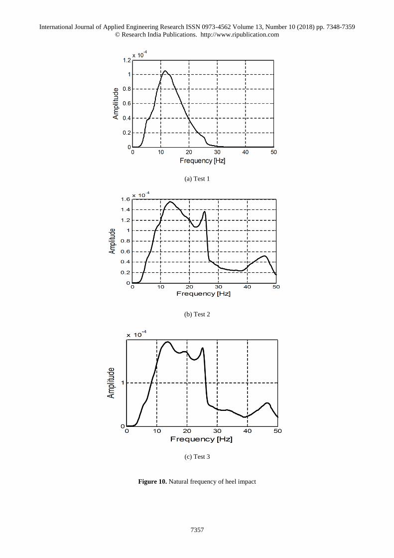
Table 6. Test results of walking load
Test Natural
frequency (Hz)
Maximum acceleration
response (s/m2)
Grade
1 9.0 0.23 1
2 13.7 0.30 1
3 11.5 0.25 1
International Journal of Applied Engineering Research ISSN 0973-4562 Volume 13, Number 10 (2018) pp. 7348-7359
© Research India Publications. http://www.ripublication.com
7356
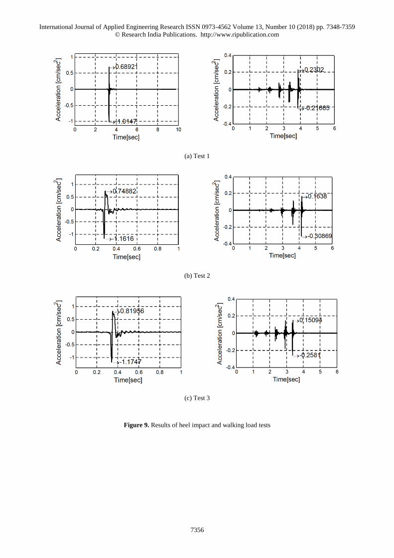
(a) Test 1
(b) Test 2
(c) Test 3
Figure 9. Results of heel impact and walking load tests
International Journal of Applied Engineering Research ISSN 0973-4562 Volume 13, Number 10 (2018) pp. 7348-7359
© Research India Publications. http://www.ripublication.com
7357
(a) Test 1
(b) Test 2
(c) Test 3
Figure 10. Natural frequency of heel impact
International Journal of Applied Engineering Research ISSN 0973-4562 Volume 13, Number 10 (2018) pp. 7348-7359
© Research India Publications. http://www.ripublication.com
7358
CONCLUSIONS
The purpose of this study was to investigate the applicability of
a voided deck slab (VDS) system that can insulate the floor
impact sounds and vibrations in apartment housing in South
Korea. The test results show that the light impact sound
insulation performance reached grade 1, and the heavy impact
sound insulation performance reached grade 3. These results
satisfy the required impact sound insulation performance of
apartment housing. Based on these results, it is expected that
the application of VDS can be useful in preventing interlayer
noise issues in apartment housing in South Korea.
In addition, the vertical vibration performance of VDS was
assessed based on the “Guidelines for evaluating residential
performance on vibration of buildings” by AIJ. The results of
the vertical vibration performance of VDS were measured as
grade 1, which applies to the living room or bedrooms of
apartment housing to insulate from annoying vibrations.
However, when the length of the slab is longer than that used
in the present research, and the size and the number of rooms
are increased, the floor impact sound is expected to be
measured as between grade 1 and grade 2. Thus, it is necessary
to conduct additional experiments to investigate the effects of
the number of rooms and the length of the span of the slabs on
the sound insulation performance of VDS.
Finally, based on the results of this study, the application of
VDS to apartment housing is considered a useful
countermeasure to reduce disputes and discomfort caused by
interlayer floor noise and vibrations in apartment housing in
South Korea. In addition, it is thought that a reduction of in the
quantity of concrete required will not only improve the
workability in construction sites, it will also reduce the
emissions of carbon dioxide. Thus, VDS will be a useful
alternative method to improving the habitability for occupants
and the workability for workers at construction sites.
REFERENCES
[1] Chung, L., et al., Investigations on Flexural Strength and Stiffness of Hollow Slabs. Advances in Structural
Engineering, 2010. 13(4): p. 591-601.
[2] Han, S.-W., et al., Evaluation of shear strength of precast-prestressed hollow slabs based on experiments. Journal of the Korea Concrete Institute,
2014. 26(5): p. 635-642.
[3] Joo, E.-H., et al., Structural Performance Test on
Installation Method of Void Former for Void Slab
using Deck Plate. Journal of the Architectural Institue
of Korea, 2011. 27(3): p. 31-38.
[4] Kang, S.-M., et al., Shear behavior investigation of biaxial hollow slabs through non-linear FE analysis. Journal of Architectural Institute of Korea Structure &
Construction, 2016. 32(12): p. 3-13.
[5] Seok, K.-Y., S.-M. Ye, and J.-W. Kang, Shear strength of one-way hollow slab according to effective cross section and reinforcement ratio. Journal of the
Korea Institute for Sturctural Maintenance and
Inspection, 2014. 18(2): p. 90-98.
[6] Yoon, S.-W., et al., Shear performance analysis of one-way hollow slab according to shear reinforcement. Journal of the Korea Institute for
Sturctural Maintenance and Inspection, 2014. 18(6):
p. 97-104.
[7] Yu, Y.-J., et al., Evaluation of flexural performance of one-way hollow slabs according to the shear reinforcement. Journal of the Korean Association for
Spatial Structures, 2014. 14(2): p. 79-86.
[8] Kang, D.H. and S.W. Han, Experiment and evaluation of the shear strength of hollow-core slab. Proceedings
of the Korea Concrete Institute, 2014. 26(2): p. 1-2.
[9] Jamal, J. and J. Jolly, A study on structural behaviour of bubble deck slab using spherical and elliptical balls. International Research Journal of Engineering
and Technology, 2017. 4(5): p. 2090-2095.
[10] Jung, M.G., H.H. Kim, and C.S. Choi, Flexural capacity of one-way void slabs with lightweight eco bean deck. Proceedings of the Korea Concrete
Institute, 2016. 29(1): p. 159-160.
[11] Hur, M.W., J.H. Yoon, and T.W. Park, Evaluation for the serviceability according to the hollow core ratio of hollow core slab. Proceedings of the Korea
Concrete Institute, 2016. 28(1).
[12] Choi, H.-M., et al., Shear performance of board-type two-way voided slab. Journal of the Korea Concrete
Institute, 2015. 27(6): p. 651-659.
[13] Ibrahim, I.S., et al., Experimental study on the shear
behaviour of precast concrete hollow core slabs with
concrete topping. Engineering Structures, 2016. 125:
p. 80-90.
[14] Aguado, J.V., et al., A 3D finite element model for
predicting the fire behavior of hollow-core slabs.
Engineering Structures, 2016. 108: p. 12-27.
[15] Bhagat, S. and K.B. Parikh, Parametric study of R.C.C voided and solid flat plate slab using SAP 2000. IOSR
Journal of Mechanical and Civil Engineering, 2014.
11(2): p. 12-16.
[16] Bhagat, S. and K.B. Parikh, Comparative study of voided flat plate slab and solid flat plate slab. International Journal of Innovative Research and
Development, 2014. 3(3): p. 22-25.
[17] Cha, S. The management system and effect of floor
noise at apartment houses. in Joint Conference by
Korean Society for Noise and Vibration Engineering.
2014.
[18] Christian, S.P., Henrik M., and P.W. Kerstin, A detailed study of low-frequency noise complaints. Journal of Low Frequency Noise, Vibration and
Active Control, 2008. 27(1): p. 1-33.
[19] Jeon, J.-Y., Subjective evaluation of floor impact noise based on the model of ACF/IACF. Journal of Sound
International Journal of Applied Engineering Research ISSN 0973-4562 Volume 13, Number 10 (2018) pp. 7348-7359
© Research India Publications. http://www.ripublication.com
7359
and Vibration, 2001. 241(1): p. 147-155.
[20] Kim, K.-W., J.-Y. Jeon, and J.-Y. Sohn, A study on the subjective evaluations of noise through floors in apartment buildings. Journal of Architectural Institute
of Korea, 1998. 18(2): p. 949-954.
[21] Lee, J.W., et al. Procedure of noise measurement
method for noise standard and improvement plan. in
Joint Conference by Korean Society for Noise and
Vibration Engineering. 2017.
[22] Chung, J., et al., An analytical study of optimal hollow sphere shapes in hollow slabs. Proceedings of
Architectural Institute of Korea, 2009. 25(1): p. 49-56.
[23] Chung, J.-H., et al., An Experimental Study for Bond
Characteristics of Deformed Bar Embedded in Donut
Type Biaxial Hollow Slab. Journal of Korea Concrete
Institute, 2013. 25(2): p. 155-163.
[24] Kim, S.-M., T.Y. Chang, and S.S. Kim, Structural performance tests of two-way void slabs. Journal of
the Architectural Institue of Korea, 2009. 25(8): p. 35-
42.
[25] Lee, Y.-E., et al., Experimental Evaluation on
Punching Shear of Two-way Void Slab-to-Column
Connection with TVS Lightweight Ball. Journal of the
Architectural Institue of Korea, 2011. 27(11): p. 71-
78.
[26] Chung, J.-H., et al., One-way shear strength of donut
type biaxial hollow slab considered hollow shapes and
materials. Journal of the Korea Concrete Institute,
2012. 24(4): p. 391-398.
[27] Lim, J., et al., Shear tests on voided slabs with board-type voiding material. Journal of Korean Society of
Hazard Mitigation, 2013. 13(6): p. 57-65.
[28] Simasathien, S. and S.-H. Chao, Shear strength of steel-fiber-reinforced deep hollow-core slabs. PCI
Journal, 2015. July-August: p. 85-101.
[29] Aldejohann, M. and M. Schnellenbach-Held,
Investigations on the shear capacity of biaxial hollow
slabs-test setup and test program. Darmstadt Concrete,
2002. 17.
[30] Schnellenbach-Held, M. and K. Pfeffer, Punching behavior of biaxial hollow slabs. Cement and
Concrete Composite, 2002. 24(6): p. 551-556.
[31] Vambersky, J.N.J.A., Hybrid structures hollow core slabs and challenging architecture. Concrete Floors
and Slabs, 2002: p. 315-326.
[32] Girhammar, U.A. and M. Pajari, Tests and analysis on
shear strength of composite slabs of hollow core units
and concrete topping. Construction and Building
Materials, 2008. 22: p. 1708-1722.
[33] Hegger, J., T. Roggerndorf, and N. Kerkeni, Shear capacity of prestressed hollow core slabs in slim floor constructions. Engineering Structures, 2009. 31(551-
559).
[34] Tina, L., Structural behaviour of BubbleDeck slabs
and their application to lightweight bridge decks, in
Department of Civil and Environmental Engineering.
2009, Massachusetts Institute of Technology.