Embed Size (px)
Citation preview
EVALUATION OF MODERN POWER SOURCE FOR GMAW WELDING EQUIPPED
WITH ADVANCED ARC CONTROL
L. Kolarik1, M. Kolarikova1, K. Kovanda1,M. Pantucek2, P. VondrouS1
1) CTU in Prague, Faculty of Mechanical EngineeringDepartment of Manufacturing Technology, Technicka 4, Prague, CR
2) Migatronic CZ, a. s., Tolstého 451, Teplice, CR
e-mail: [email protected]
Keywords Welding, GMAW, IAC, Sequence Repeat, Short Arc,
Heat Input, Arc Control
1. IntroductionAim of this research is to understand main advantage of using modern GMAW welding sources equipped with special pulse control functions. To evaluate and present to readers influence of pulse, respectively arc control during welding, the comparison of our experimental results using and non-using these modern pulse control functions was done. The main goal is to objectively compare experimental results with the information advertised by welding source manufactures about these functions.
At the present industrial welding praxis, GMAW (Gas Metal Arc Welding) is the most widely used welding technology. There are numerous advantages of GMAW as stated in tab. 1. Disadvantages are connected with the fact that the consumable electrode is melting away and this is causing voltage and current change, thus the heat input is varying in time and the process is partly unstable.
Wide range of welding current: 30-600 A (800 A)
Wide range of materials: steel, high strength, Al alloys
Easy automation
High deposition rate
Modern welding power sources are equipped with special functions of arc control. These functions measure and adjust
welding parameters during welding with minimum time delay so that the right parameters are set. At the Laboratory of welding technologies of CTU in Prague we have used modern welding source by Migatronic – Sigma Galaxy equipped with functions
Intelligent Arc Control and Sequence Repeat. According to manufacturer these functions significantly improve welding
process by stabilizing arc. This leads to lower heat input, deformation and improves weld quality. Single V butt welds
were done on S275J2 of 10 mm thickness (2 weld layers: root + capping layer) in PF and PG positions. Also we have welded
thin sheets with uneven root gap in PG position. Welding current, voltage was monitored by Welding Information System and compared with standard short arc GMAW welding. Results
have shown that these “intelligent” functions offer significant advantages for welding of steels, especially in vertical positions, for welding of thin sheets, because they stabilize arc, lower heat
input and thus improveweld metal control.
As for any manufacturing technology, industry demands from GMAW welding process increasing efficiency, economy and welding speed while keeping the weld quality high (or improved) and decreasing demands on welders’ skills and qualification. Another industrial challenging demands are e.g. welding in overhead (PD, PE) and vertical positions (PF, PG), bridging wide root opening, uneven root opening, easiness of parameters setting. Important trends of GMAW development is also to apply GMAW in domain of GTAW welding, i.e. welding of high strength steels, welding of non-ferrous materials and heterogeneous joints. This can be done by precise heat input control.
Development of modern microelectronics has enabled fast development of welding sources. By use of fast microelectronic circuits, speed of welding process control and welding parameters adjustment has increased tremendously, thus dynamic control over arc and molten metal transfer became possible. Research and development done by welding sources manufactures is basically focused upon fast control and regulation of welding parameters during welding as necessary for the welding operation. This is executed by measuring and adjusting arc current and voltage with high frequency according to program (function) already loaded into the memory of welding source. The modern welding sources are equipped with special control functions (programs) of arc and molten metal transfer focusing on 2 basic areas. First area of focus is welding of thin metal sheets (0.5- 3 mm) and the second searches high productivity thick metal sheets welding (over 5 mm).– Thin metal sheet welding – Highest priority in thin sheets welding
is to stabilize and lower heat input to reduce risk of burn-through, to reduce warping, improve melt pool control, lower spatter. This can mainly be reached by stabilizing and controlling arc. With this in mind, many welding sources manufacturers have developed pulse control functions incorporated into their welding sources, e.g. CMT (Fronius), STT (Lincoln Electric), Cold Arc (EWM), SAT (ESAB) [Kolarik 2011, Lincoln 2006, ESAB 2009].
– Thick sheet welding – Highest priority is in maximizing weld metal deposition rate when heat input and spatter is low. For sheet over 5 mm welding sources with functions as e.g. Force Arc (EWM), Power Arc (Migatronic), Aristo SuperPulse (ESAB) tandem welding, T.I.M.E. (Fronius) can be named [Fronius 2009, Fronius 2011, Migatronic 2010].
For our research Migatronic welding source Sigma 400 Galaxy equipped with function IAC (Intelligent Arc Control) and Sequence Repeat was used. Short introduction of these functions as advertised by Migatronic is being shown:
1.1 Function IAC – Intelligent Arc ControlThis function is specially focused on welding of thin sheets and root welds, bridging wide and uneven weld gaps, welding in vertical positions PF, PG. Function offers lower spatter, high arc stability, low heat input. IAC function is changing current and voltage in time compared to standard short arc, see comparison Fig. 3 (data from this research). The pulse can be described as follows: During molten metal drop separation, when short circuiting is just finished, the current pulse with low value is used to suppress significantly spatter [Migatronic 2011].
1.2 Function Sequence RepeatThis function is combining 2 molten metal transfer modes periodically, e.g. combination of short arc and pulsed transfer mode. Short arc has lower welding parameters (less heat input) and pulsed transfer mode has higher parameters (higher heat input). This is advantageous for welding in difficult positions PC, PD, PE, PF or PG. When applied to V-joint butt weld, welder can do weave movement without dwell over beveled face. Usually this dwell is needed to distribute heat as necessary. Pulsed transfer is used when torch is over beveled faces T able 1. Advantages of GMAW

EVALUATION OF MODERN POWER SOURCE FOR GMAW WELDING EQUIPPED WITH ADVANCED ARC CONTROL | July | 2012 | 322/323
(to assure side wall fusion), short arc is used when over central part of the weld, to prevent excessive reinforcement. Thus continuous weave movement is possible, making weave movement easier for welder [Havelka 2011].
2. ExperimentalExperiment was designed to evaluate use of functions IAC and Sequence Repeat by comparing the welding results using these functions and non-using them. To realize this comparison 4 different samples were welded, for reference see Tab. 2.
All welding was done at welding laboratory of CTU in Prague equipped with power source Migatronic Sigma 400 Galaxy, equipped with IAC and Sequence Repeat functions. All layers were welded in difficult vertical positions PF or PG. To observe evolution of U, I in time, monitoring unit „WIS“ (Welding Information System) was connected to welding source to record time evolution of welding parameters I, U, v, etc.
Sample A B C D
Thickness 10 mm 3 mm
Size 225x80 mm 210x80 mm
Welding passes, metal
transfer
2 layers Root – IACCap –Seq.
Rep.
2 layers Root – short
arcCap – short
arc
1 layer Root – IAC
1 layer Root – short
arc
C Mn Si P S Al
Max. 0.22% Max. 1.6% Max. 0.55% Max. 0.035% Max. 0.035% 0.01 – 0.06%
Rm = 410 ÷ 560 [MPa] Rp0,2 = 275 [MPa] A5 = 21 [%]
T able 2. Base metal composition and mechanical properties- S275J2 state according to DIN EN 10025–2 [Furbacher 2001]
Figure 1. Weld sample A, B – welding position PG
Figure 2. Sample C, D– sample preparation
2.1 Samples A, B – 10 mm thick Sample thick 10 mm needed 2 layers, root layer and capping layer. Root weld was done in vertical downward PG position for sample A and B, as at Fig. 1. Welding in PG position is considered difficult position for root welds because it usually does not offer good penetration and often has problem of insufficient root penetration. This is caused by gravity force influencing molten pool movement (dripping). Capping layer was done with weave movement and in vertical upward position PF. PF position is also considering difficult, but easier than PG. Robotic welding by Fanuc robot was used.
Structural steel S275J2 thick 10 mm was used. Composition and basic properties are at Tab. 3. Typical filler material for these steels from ESAB, OK Autrod 12.56, diameter 1 mm, was used. Base metal sheet size is 200 x 80 mm, thickness 10 mm, was used. V-joint with groove angle 70° and root opening 3,2 mm. Shielding gas is M21, mixture of 82% Ar + 18% CO2.
T able 3. Base metal composition and mechanical properties- S275J2 state according to DIN EN 10025–2 [Furbacher 2001]
2.2 Samples C, D – 3 mm thickSample thick 3 mm needed only 1 layer. Weld was done in vertical downward PG position for sample C and D. In this case we wanted to evaluate the advertised possibility of IAC functions to bridge wide and uneven root openings. To realize this, we have prepared sample with uneven root opening, narrow at the top, very wide at the bottom, as at Fig. 2. Manual welding was used for these samples, because this uneven opening can be bridged over only using adjustment during welding by skilled worker (difficult to create such program for robot).
3. Results3.1 Samples A, B – 10 mm thickWelding parameters used for samples A, B are stated in Tab. 4. Setting optimum parameters for A sample was easier, already 1st sample was successful. Creating good weld without advanced functions, with standard short arc needed 3 B test samples, because of difficult root welding.
3.1.1 Root weld – Welding parameters settingTo create sound weld it was necessary to adjust welding parameters especially for sample B. Welding parameters are welding speed 0.10 m.min–1, current 80 A, voltage 16 V, weave movement setting: frequency 2 Hz, amplitude 1.5 mm, dwell 0.4 s.
Sample A: Function IAC was used with upper stated parameters. Weld had sufficient root penetration and at both faces as well, metallography at Fig. 5. Arc was stable. Molten pool was not dripping. No spatter was found. Weld quality is high, without any defect.

Sample Weld width [mm] Weld reinforcement [mm] Root width [mm] Root reinforcement [mm] HAZ width at root [mm]
A 11 1,9 4 0,3 14
B3 12 1,8 6 -0,5 16
Sample Function,metal transfer Weld pass Current
[A]Voltage
[V]Wire feed [m.min–1]
Welding speed [mm.s–1]
Heat input[kJ.mm–1] Result
A
IAC root 80 15.5 2.5
1.7
0.59 OK Figure 5
Sequence Repeat capping 85 short arc150 pulsed
1626.4
2.66.7
0.66 (0.6 s)1.90 (0.3 s)
AVG 1.1OK Figure 6
B1 Short arc root 80 16.3 2.5 0.63 NG
B2 Short arc root 100 17 3.3 0.82 NG
B3Short arc root 130 18.5 4.9 1.16 OK Figure 7
Short arc capping 145 19.2 5.6 1.34 OK Figure 8
T able 4. Welding parameters – 10 mm thick samples A, B
Sample B: When current 80 A was set up on the welding source without using IAC function, the welding process was very unstable. Arc was unstable, heat input was insufficient, joint faces not completely fused. Only 1 joint face was melted. To stabilize process and to fuse both join faces, current was needed to be increased to 100 A and to 130 A. Only at 130 A welding process was stabilized, but the root of the weld had concave shape (welding defect: root concavity) as visible at Fig. 7. This is in concordance with known fact, that short arc in PG position is not suitable for formation of root weld. PF position would be more suitable.
Figure 3. Current, voltage time evolution for root weld – Left: Sample A- IAC function 80 A, Right: Sample B- short arc transfer 130 A
Figure 4. Current, voltage time evolution for Sequence Repeat weld
T able 5. Measured weld geometry
Figure 5. Sample A – root IAC 80 A
Figure 7. Sample B3 – root, short arc 130 A
Figure 6. Sample A – capping layer,Sequence repeat 85 A/150 A
Figure 8. Sample B3 –cap, short arc 145 A
3.1.2 Capping weld – Welding parameters settingCapping welds were done in vertical upward PF position.
Sample A: Function Sequence Repeat was used for capping layer. Function Sequence Repeat was changing metal transfer mode periodically from IAC short arc to pulse transfer, as visible at Fig. 6. Setting of function was: IAC short arc transfer 85 A for period 0.6 s, pulsed arc transfer 150 A for period 0.3 s. Result is at Fig. 7.
During phases of pulsed arc (higher heat input), torch was heating up weld faces. During IAC short arc (lower heat input), torch was in between faces.
Sample B: To melt both joint faces well, the current was needed to be increased to 145 A. Result visible at Fig. 8. Welding parameters that have been set are shown in Tab. 4.
Measured time evolution of current and voltage for root weld of sample A and sample B3 is shown at Fig. 3. At this picture the difference of standard short arc transfer and IAC function short arc transfer is easily visible.
EVALUATION OF MODERN POWER SOURCE FOR GMAW WELDING EQUIPPED WITH ADVANCED ARC CONTROL | July | 2012 | 324/325
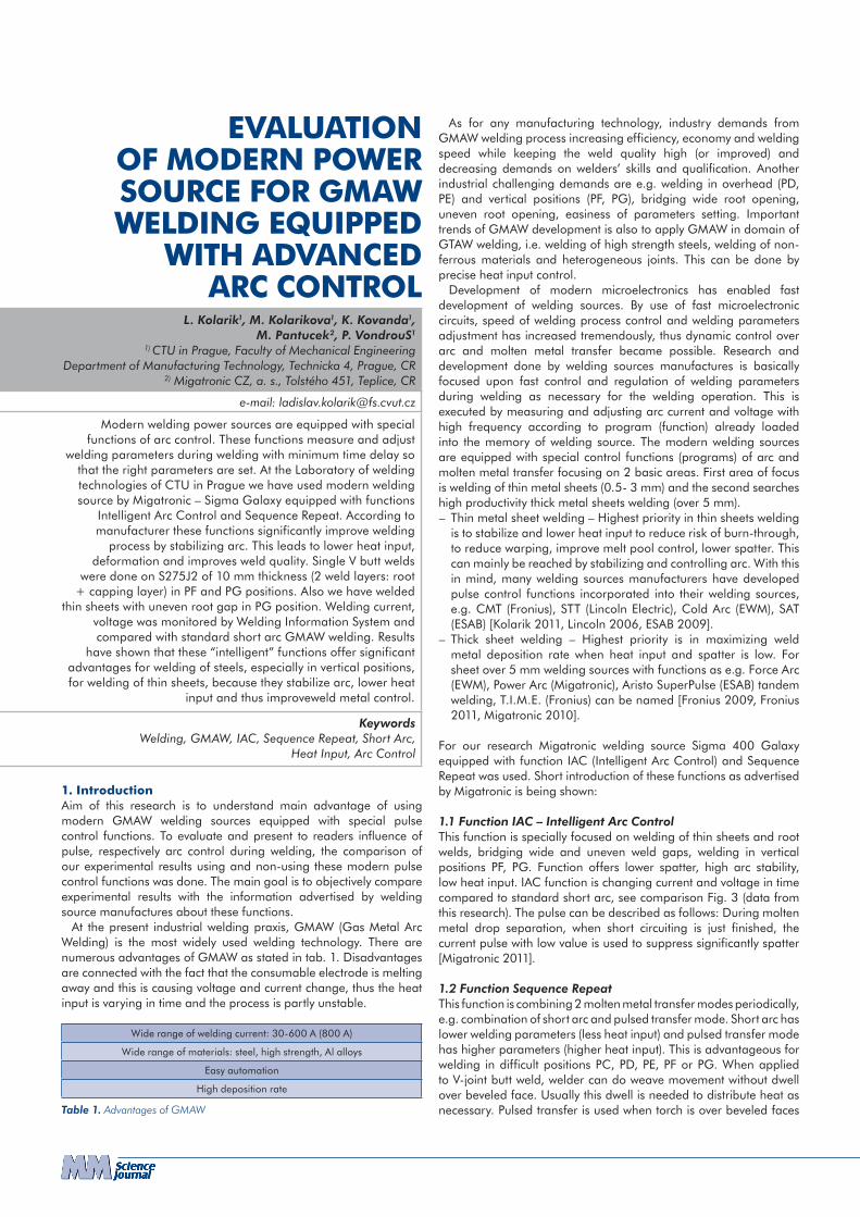
Sample Function, metal transfer Weld pass Current
[A]Voltage
[V]Wire feed [m.min–1]
Welding speed [mm.s–1]
Heat input[kJ.mm–1] Result
C IAC root 80 15.5 2.5Manual
welding1–1.5
0.59 OK, Figure 9, Figure 10
D Short arc root 105 16 3.5 1.0 Partly OK, Figure 11, Figure 12
Figure 9. Sample C – root weld,IAC 80 A, weld upper side
Figure 11. Sample D – root welded withStandard arc 105 A, weld upper side
Figure 10. Sample C – root weld,IAC 80 A, weld lower side
Figure 12. Sample D – root welded with Standard arc 105 A, weld bottom side
Short arc transfer (right side) – when metal drop touches the weld pool, current raises to maximum values, voltage drops to 0 V. During short cutting there is no arc and current is increasing to maximum value limited by the power source.
Using IAC function (left side), the voltage and current time evolution is distinctly different from standard short arc. The current is rising during the shortcut, but power source after certain time sharply decreases voltage, by which current is also decreased. This sharp energy drop slower down melt drop transfer and spatter is reduced significantly. The voltage and current are raised again to start arc again in stable manner.
Weld geometry for sample A, B are shown at Tab. 5. The lowest width of the HAZ at root was measured for sample A, welded with IAC function (80 A), 14 mm. Sample B1 for the same current (80 A) did have lack of penetration and lack of fusion and when the current was increased to 130 A, B3 sample, the HAZ size was 16 mm, higher than for A sample.
3.2 Samples C, D – 3 mm thickSamples were welded with parameters stated in Tab. 6. Because manual welding was used welding speed was not constant. Higher welding speed was at the lower gap, lower at the bottom, where the welder needed to bridge much wider gap of root opening.
3.2.1 C sample – IACThe results of sample welded with function IAC are shown at Fig. 9 (weld upper side) and at Fig. 10 (weld bottom). The welding process was very stable, even at the end, where the root opening reached 10 mm. The only defect visible was at the beginning of welding, with small root opening, there is lack of penetration (15 mm long), the material was not heated yet. The weld is of good quality for root opening in wide range 2–10 mm.
3.2.2 D sample – standard short arcThe sample welded with standard short arc metal transfer are shown at Fig. 11 (upper side), bottom side at Fig. 12 (weld bottom). By observation of the welds, defects can be noted. There is lack of penetration (15 mm + 10 mm long) at the weld beginning,
T able 6. Welding parameters – 3 mm thick samples C, D
significantly longer than when IAC used. From the 2nd third of weld length the arc was unstable and irregularly extinguished. It caused that wire partly passed through root opening without being melted. The weld had good quality for the root opening in range 3-7 mm. It should be noted that the results can be improved by training the welder respectively. The results are very much dependent on welder s skill.
4. ConclusionThe first experiment, welding of 10 mm thick plate, affirmed advantages of IAC function welding compared to standard short arc for root layer welding in difficult downward PG position. We noticed good root penetration at sample A (IAC), while not good at sample B (standard short arc).
Also for the thin 3 mm sheet with uneven root opening the IAC function proved to give more stable results, because of arc control. IAC arc gave good results in range 2–10 mm of root opening, while standard short arc served well at range 3 – 7 mm. It needs to be stated that usually to weld thin sheet, the root opening is 2 – 4 mm (10 mm is thus not necessary).
It was proved by measurement that IAC function controls voltage and current so that heat input into the weld can be much lowered. The special shape of pulse is helping to maintain the arc stable even at lower parameters. We have measured decrease in heat input by IAC for root layer by almost 50 %. Compared to standard arc, IAC can be considered to be “colder welding”.
Function Sequence Repeat is advantageous for filling, capping passes because lowering total heat input by controlling voltage and current evolution. Overall heat input is lower using this function compared to standard short arc. Good weld was gained in PF position and heat affected zone size was reduced compared to standard short arc.
The development of electronics and programming has enabled creation of special functions that can improve behavior of arc and melt transfer, making the welding stable even with lower parameters. These functions certainly improve some aspects of welding process and they also make welding easier for welders, by facilitate parameters setting, welding in difficult positions etc.

AcknowledgementThis research was supported by the grant SGS OHK 2-038/10.
References[ESAB 2009] ESAB. Swift Arc Transfer [online]. 2009 [cit. 2012-03–29]. Available on: http://products.esab.com/ESABImages/Swift_Art_Transfer_final.pdf [Fronius 2011] Fronius. TIME and TimeTwin welding [online]. 2011 [cit. 2012-05–29]. Available on: http://www.fronius.com/cps/rde/xchg/fronius_international/hs.xsl/ 79_9163_ENG_HTML.htm [Fronius 2009] Fronius. Increase Your Knowledge (in Czech) [online]. 2009 [cit. 2004-9- 13]. Available on: http://www.fronius.com/cps/rde/xchg/SID-77958394–23586247/ fronius_ceska_repub lika/hs.xsl/29_104.htm[Furbacher 2001] Furbacher, I.; MACEK, K.; SEIDL, J. – et al: Lexicon of Technical Materials, volume 1 (in Czech)., Praha: Verlag Dashöfer, 2001[Havelka 2011] Havelka, P.: Evolution of Cold Arc Welding (in Czech). World of welding, 2011, vol. 15, No. 1, page 12. ISSN 1214-4983.[Kolarik 2011] Kolarik, L. – et al: GMA Welding of Steels by Force Arc
(in Czech). TechMat 2011, Pardubice: Univerzita Pardubice, 2011, ISBN 978-80-7395-431-4[Lincoln 2006] Lincoln Electric. Surface Tension Transfer [online]. 2006 [cit. 2012-03–29]. Available on: http://www.lincolnelectric.com/assets/en_US/Products/literature/ NX220.pdf [Migatronic 2011] Department of Research and Development, Migatronic. Intelligent Arc Control – process to reduce spatter and heat input, during the short arc (in Czech). World of welding, 2011, vol. 15, No. 3, page 12–14. ISSN 1214-4983.[Migatronic 2010] Migatronic. Improved quality and higher productivity from energy-dense PowerArc technology for thick-plate welding [online]. 2010 [cit. 2012-03–29]. Available at: http://www.migatronic.com/default.aspx?m=4&i=115&pi=1&pr=0
ContactsIng. Ladislav Kolarik, IWEDepartment of Manufacturing TechnologyFaculty of Mechanical Engineering CTU in PragueTechnicka 4, 166 07 Prague, Czech Republictel.: +420 224 352 630, e-mail: [email protected]