Embed Size (px)
Citation preview
Evaluation of Mechanically Stabilized Earth (MSE)Walls for Bridge Ends in Kentucky; What Next?
Research ReportKTC -13-11/SPR443-12-1F
KentuckyTransportation
Center
Our MissionWe provide services to the transportation community through research,
technology transfer and education. We create and participate in partnerships to promote safe and effective transportation systems.
Kentucky Transportation Center176 Oliver H. Raymond Building
Lexington, KY 40506-0281(859) 257-4513
fax (859) 257-1815
www.ktc.uky.edu
© 2013 University of Kentucky, Kentucky Transportation CenterInformation may not be used, reproduced, or republished without our written consent.
Research Report KTC-13-11/SPR443-12-1F
EVALUATION OF MECHANICALLY
STABILIZED EARTH (MSE) WALLS FOR BRIDGE ENDS IN KENTUCKY; WHAT NEXT?
by Charlie Sun Clark Graves Research Engineer Program Manger
Kentucky Transportation Center College of Engineering University of Kentucky
in cooperation with the Kentucky Transportation Cabinet The Commonwealth of Kentucky
and Federal Highway Administration
The contents of this report reflect the views of the authors, who are responsible for the facts and accuracy of the data herein. The contents do not necessarily reflect the official views or policies of the University of Kentucky, Kentucky Transportation Cabinet, nor the Federal Highway Administration. This report does not constitute a standard, specification, or regulation.
July 2013
Abstract ii
1. Report No.
KTC-13-11/SPR443-12-1F 2. Government Accession No.
3. Recipient’s Catalog No.
4. Title and Subtitle Evaluation of Mechanically Stabilized Earth Walls for Bridge Ends in Kentucky; What Next?
5. Report Date July 2013
6. Performing Organization Code 8. Performing Organization Report No.
KTC-13-11/SPR443-12-1F
7. Authors Charlie Sun and Clark Graves
10. Work Unit No. (TRIAS)
9. Performing Organization Name and Address University of Kentucky College of Engineering Kentucky Transportation Center 176 Oliver Raymond Building Lexington, KY 40506-0281
11. Contract or Grant No. KYSPR-12-443
12. Sponsoring Agency Name and Address Kentucky Transportation Cabinet 200 Mero Street Frankfort, KY 40622
13. Type of Report and Period Covered Final
14.Sponsoring Agency Code
15. Supplementary Notes Prepared in cooperation with the Federal Highway Administration, US Department of Transportation
16. Abstract This report summarizes the nationwide survey results on MSE wall abutment status. Many of handy features in MSE Wall Abutment Inspection/Rating In KY web application are highlighted, and various graphical user interfaces of the web application are illustrated and described. The inspection/rating results for fifty-six (56) existing MSE wall abutments are presented and discussed. 17. Key Words
Mechanically Stabilized Earth Wall, MSE Wall, Abutment, Bridge End, Rating
18. Distribution Statement Unlimited, with approval of the Kentucky Transportation Cabinet
19. Security Classification (of this report) None
20. Security Classification (of this page) None
21. No. of Pages 60
22. Price
Form DOT 1700.7 (8-72)Reproduction of completed page authorized
Table of Contents iii
TABLE OF CONTENTS
LIST OF FIGURES ............................................................................................................................. vi LIST OF TABLES ............................................................................................................................... ix ACKNOWLEDGEMENTS ................................................................................................................... x EXECUTIVE SUMMARY .................................................................................................................. xi 1. INTRODUCTION .......................................................................................................................... 1
1.1 Background ...................................................................................................................... 1 1.2 Problem Statement ......................................................................................................... 1 1.3 Objectives ....................................................................................................................... 1
2. PRIMARY REFERENCE SOURCE FOR MSE WALLS ............................................................. 3
3. NATIONWIDE MSE WALL STATUS SURVEY ......................................................................... 4
3.1 General Information ....................................................................................................... 11 3.2 Materials Used for MSE Wall Abutment .................................................................... 11 3.3 Maximum Height for MSE Wall Abutment ............................................................. 12 3.4 Foundation for MSE Wall Abutment .......................................................................... 12
3.5 What Are Bridge Beams/Girders Allowed on ............................................................... 12 3.6 MSE Wall Abutment Failure and Failure Type .......................................................... 12 3.7 Rating System, Guidelines, and Handbook Availability .......................................... 12 3.8 Comments from Respondents ...................................................................................... 12
4. MSE WALL ABUTMENT CONDITION RATING WEB APPLICATION ............................... 15
4.1 Overall Web Page Setting ............................................................................................. 16 4.2 Register ......................................................................................................................... 18 4.3 Login ............................................................................................................................ 21 4.4 MSE Wall Abutment Inspection/Rating In KY Web Application Home ................. 21
Table of Contents iv
4.5 Search MSE Walls and “go” ....................................................................................... 22 4.6 MSE Wall Abutment List ............................................................................................ 23 4.7 Click Here To See Them on Map ................................................................................. 24 4.8 All on Map ................................................................................................................... 26 4.9 FAQ .............................................................................................................................. 27 4.10 Contact Us ................................................................................................................... 28 4.11 Input New MSE Wall ................................................................................................ 29 4.12 Upload Files ............................................................................................................... 30 4.13 MSE Wall Detail Information ..................................................................................... 32
4.13.1 MSE Wall Info. .......................................................................................... 32
4.13.2 Inspection/Rating ....................................................................................... 33
4.13.3 Pictures/Attachments ................................................................................. 34
4.13.4 Comments ................................................................................................... 35
4.13.5 My Comment .............................................................................................. 36 4.14 Inspection/Rating Detail Information ......................................................................... 37
4.14.1 Inspection/Rating ....................................................................................... 37
4.14.2 Pictures/Attachments ................................................................................. 38
4.14.3 Comments ................................................................................................... 39
4.14.4 My Comment .............................................................................................. 40 4.15 My Account ............................................................................................................... 41 4.16 User Administrator ..................................................................................................... 42
4.16.1 Pending Agency/PI .................................................................................... 42
4.16.2 All Existing Users ...................................................................................... 45
4.16.3 Corresponding Administrator .................................................................... 47
Table of Contents v
4.16.4 Add New User ............................................................................................ 48
4.17 Logout ........................................................................................................................ 49
5. VISITED MSE WALL ABUTMENTS IN KENTUCKY ............................................................ 50
5.1 General Information ...................................................................................................... 50 5.2 Backfill Material ........................................................................................................... 53 5.3 Reinforcement for Wall................................................................................................ 53 5.4 Visual Rating after Inspection .................................................................................... 53
6. DESIGN GUIDANCE, CONSTRUCTION AND MAINTENANCE INSPECTOR’S HANDBOOK ....................................................................................................... 55
6.1 Design Guidance ............................................................................................................ 55 6.2 Construction and Maintenance Inspector’s Handbook ............................................. 55
7. CONCLUSIONS AND RECOMMENDATIONS ....................................................................... 56 REFERENCES .................................................................................................................................... 58
List of Figures vi
LIST OF FIGURES Figure 1. How Many States/Provinces Use MSE Wall as Abutment .............................................. 4 Figure 2. How Many States/Provinces Use MSE Wall as Abutment before .................................. 4 Figure 3. Who Will Use MSE Wall Abutments ................................................................................ 5 Figure 4. Types of Reinforcements Were Used in the MSE Wall Abutments ................................ 5 Figure 5. Types of Backfill Materials Were Used in the MSE Wall ............................................... 6 Figure 6. The Maximum Height for the MSE Wall Abutments ....................................................... 6 Figure 7. MSE Wall Footing Is Allowed to Build on ...................................................................... 7 Figure 8. Bridge Beams/Girders Are Bearing on ............................................................................. 7 Figure 9. MSE Wall Abutment Failures in States ............................................................................ 8 Figure 10. MSE Wall Failure Frequency Distribution ...................................................................... 8 Figure 11. MSE Wall Abutment Failures Type Distribution ............................................................ 9 Figure 12. Formalized Maintenance Rating System in States ....................................................... 10 Figure 13. Guidelines for Building MSE Wall Abutments ............................................................. 10 Figure 14. Maintenance Inspector’s Handbook for MSE Wall Abutments .................................. 11 Figure 15. Overall Web Page Setting 1 – Before Login ................................................................ 17 Figure 16. Overall Web Page Setting 2 – After Login ................................................................... 17 Figure 17. Registration Screen .......................................................................................................... 18 Figure 18. Information after Register Button Is Clicked . .............................................................. 19 Figure 19. Email Provides a Link to Activate User’s Account ...................................................... 19 Figure 20. Screen after Activating User’s Account ......................................................................... 20 Figure 21a. Select User Category from Dropdown List ................................................................ 21 Figure 21b. Login Screen ................................................................................................................. 21 Figure 22. Handy Function – Search MSE Walls and “go” .......................................................... 22
List of Figures vii
Figure 23. Search Result by Using Search MSE Walls with String “seatonville” ........................ 22 Figure 24. Functions for Administrator Only .................................................................................. 23 Figure 25. Click Here To See Them on Map Shows Searched MSE Wall Abutment Sites,
Which Have Lat/Long Coordinates, on a Map ............................................................ 24 Figure 26. A Map Showing Searched Sites Is Presented after the Link, Click Here To
See Them on Map, Is Clicked ........................................................................................ 25 Figure 27. ALL ON MAP Shows All the Sites, Which Have Lat/Long Coordinates, on a
Map .................................................................................................................................. 26 Figure 28. FAQ Page with Two Convenient Links ........................................................................ 27 Figure 29. Contact Us Screen .......................................................................................................... 28 Figure 30. Screen for Inputting New Site ....................................................................................... 29 Figure 31. Screen for Uploading Files When Submitting New Site ............................................. 30 Figure 32. Screen for Uploading Files When Registered User Re-visits Her/His Own
Site .................................................................................................................................. 31 Figure 33. MSE Wall Detail Information ....................................................................................... 32 Figure 34. Inspection/Rating Tab Shows All the Ratings for Current Site ................................... 33 Figure 35. Pictures/Attachments Lists All the Uploaded Attachments for this MSE Wall
Abutment; New Attachments Will Be Uploaded from Here as Well ........................ 34 Figure 36. Comments by Other Registered Users and Responses by Principal
Investigator for Current MSE Wall Abutment Site ..................................................... 35 Figure 37. Register User Enters Comments Here for Current MSE Wall Abutment Site
and Selected Visit Number ........................................................................................... 36 Figure 38. Inspection/Rating Tab Shows Detail Information for Selected Visit .......................... 37 Figure 39. Uploaded Pictures/Attachments for Selected Visit are Listed under
Pictures/Attachments Tab; New Attachments for This Selected Visit Will Be Uploaded from Here as Well .......................................................................... 38
Figure 40. Comments by Other Registered Users And Responses by the Principal
Investigator for Current Site .......................................................................................... 39
List of Figures viii
Figure 41. Register User Enters Comments Here for Selected Visit ............................................. 40 Figure 42. Update User’s Account from My Account Link .......................................................... 41 Figure 43. User Administration Page with Agency and PI in Pending ......................................... 42 Figure 44. The Box under Agency Requests Is Clicked, a Dropdown List with a
Pending Agency Appears ............................................................................................... 43 Figure 45. When the Box Under Principal Investigator Requests Unverified Is Clicked,
a Dropdown List with a Pending Vendor Appears ...................................................... 43 Figure 46. There Is No Approval Pending ....................................................................................... 44 Figure 47. All the Existing Users Are Listed When the Box under All Existing Users Is
Clicked ............................................................................................................................ 45 Figure 48. User’s Detail Information Appears When a User Is Selected, and Button
User Information Is Clicked .......................................................................................... 46 Figure 49. Set up Corresponding Administrator ............................................................................ 47 Figure 50. Create a New User’s Account ........................................................................................ 48 Figure 51. Logout Link Is Shown at The Top Rightmost Corner on Every Web Page for
Convenience ................................................................................................................... 49 Figure 52. Visited MSE Wall Abutment in Kentucky ................................................................... 50 Figure 53. Twenty-seven (27) MSE Wall Abutments in Jefferson County ................................... 51 Figure 54. MSE Wall Abutment Distribution by County .............................................................. 51 Figure 55. Twenty-seven (27) MSE Wall Abutment Distribution by Route ................................ 52 Figure 56. MSE Wall Abutment Distribution by Height ............................................................... 52 Figure 57. Backfill Materials for MSE Wall Abutments ............................................................... 53

List of Tables ix
LIST OF TABLES
Table 1. Comments from Respondents .........................................................................................13

Acknowledgements
x
ACKNOWLEDGEMENTS The authors wish to thank and acknowledge the members of the Study Advisory Committee. Their guidance and advice during the course of this study was most helpful. In particular, the authors would like to thank Ms. Boday Borres, Manager of Quality Assurance Branch (QAB) of Project Development and Chairman of the Study Advisory Committee, for her leadership.
Executive Summary
xi
EXECUTIVE SUMMARY
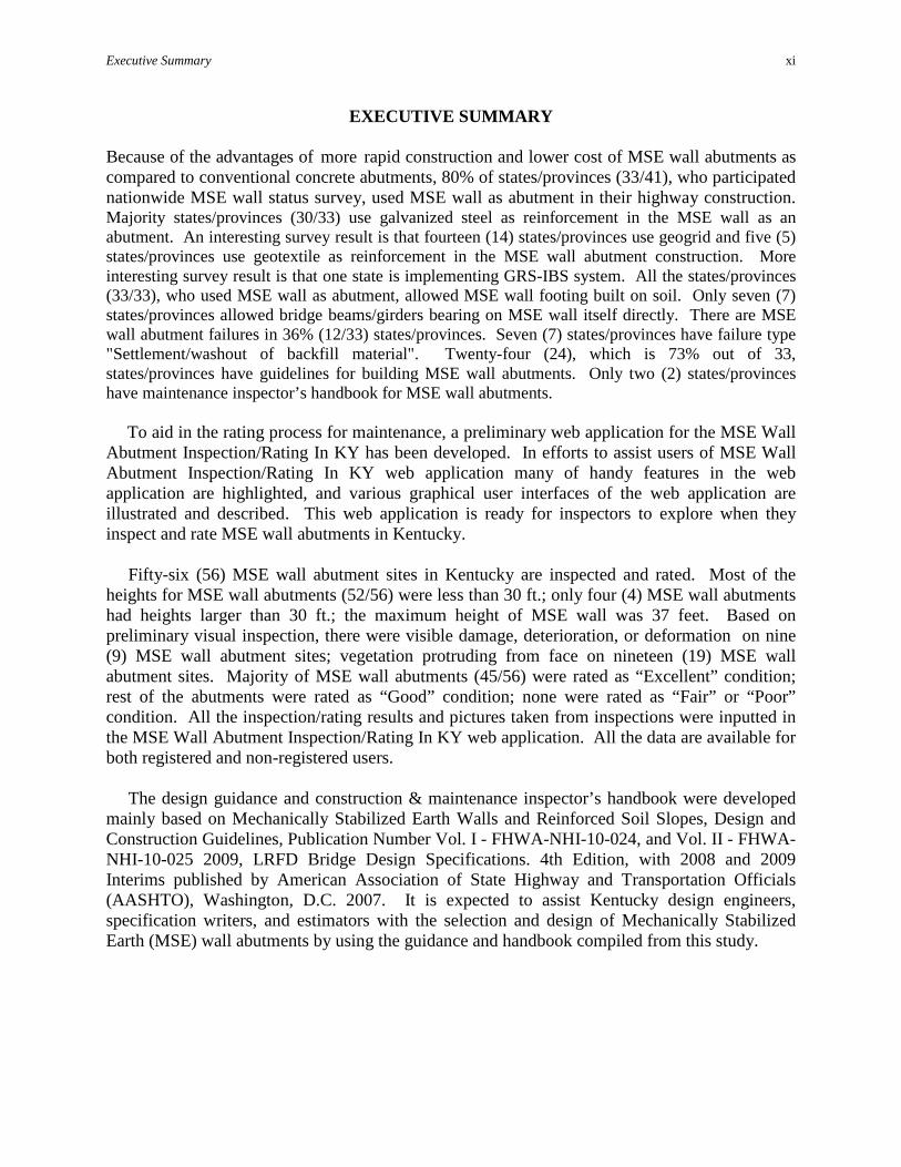
Because of the advantages of more rapid construction and lower cost of MSE wall abutments as compared to conventional concrete abutments, 80% of states/provinces (33/41), who participated nationwide MSE wall status survey, used MSE wall as abutment in their highway construction. Majority states/provinces (30/33) use galvanized steel as reinforcement in the MSE wall as an abutment. An interesting survey result is that fourteen (14) states/provinces use geogrid and five (5) states/provinces use geotextile as reinforcement in the MSE wall abutment construction. More interesting survey result is that one state is implementing GRS-IBS system. All the states/provinces (33/33), who used MSE wall as abutment, allowed MSE wall footing built on soil. Only seven (7) states/provinces allowed bridge beams/girders bearing on MSE wall itself directly. There are MSE wall abutment failures in 36% (12/33) states/provinces. Seven (7) states/provinces have failure type "Settlement/washout of backfill material". Twenty-four (24), which is 73% out of 33, states/provinces have guidelines for building MSE wall abutments. Only two (2) states/provinces have maintenance inspector’s handbook for MSE wall abutments. To aid in the rating process for maintenance, a preliminary web application for the MSE Wall Abutment Inspection/Rating In KY has been developed. In efforts to assist users of MSE Wall Abutment Inspection/Rating In KY web application many of handy features in the web application are highlighted, and various graphical user interfaces of the web application are illustrated and described. This web application is ready for inspectors to explore when they inspect and rate MSE wall abutments in Kentucky. Fifty-six (56) MSE wall abutment sites in Kentucky are inspected and rated. Most of the heights for MSE wall abutments (52/56) were less than 30 ft.; only four (4) MSE wall abutments had heights larger than 30 ft.; the maximum height of MSE wall was 37 feet. Based on preliminary visual inspection, there were visible damage, deterioration, or deformation on nine (9) MSE wall abutment sites; vegetation protruding from face on nineteen (19) MSE wall abutment sites. Majority of MSE wall abutments (45/56) were rated as “Excellent” condition; rest of the abutments were rated as “Good” condition; none were rated as “Fair” or “Poor” condition. All the inspection/rating results and pictures taken from inspections were inputted in the MSE Wall Abutment Inspection/Rating In KY web application. All the data are available for both registered and non-registered users. The design guidance and construction & maintenance inspector’s handbook were developed mainly based on Mechanically Stabilized Earth Walls and Reinforced Soil Slopes, Design and Construction Guidelines, Publication Number Vol. I - FHWA-NHI-10-024, and Vol. II - FHWA-NHI-10-025 2009, LRFD Bridge Design Specifications. 4th Edition, with 2008 and 2009 Interims published by American Association of State Highway and Transportation Officials (AASHTO), Washington, D.C. 2007. It is expected to assist Kentucky design engineers, specification writers, and estimators with the selection and design of Mechanically Stabilized Earth (MSE) wall abutments by using the guidance and handbook compiled from this study.
1. INTRODUCTION 1.1 Background
Retaining structures are essential elements of every highway design. For many years, retaining structures were almost exclusively made of reinforced concrete and were designed as gravity or cantilever walls which cannot accommodate significant differential settlements unless founded on deep foundations. When the height of retaining structures increases and poor subsoil conditions exist, the cost of reinforced concrete retaining walls increases rapidly. MSE walls offer significant technical and cost advantages over conventional reinforced concrete retaining structures at sites with poor foundation conditions. The first reinforced earth bridge abutments were constructed in France in 1969 and in the United States in 1974. These MSE structures were "true" abutments where the bridge beams rested on a spread footing beam seat bearing directly on the reinforced backfill. Mixed abutments, with piles supporting the beam seat, were developed later. One of the first true abutments in France carried a remarkable 76 m span; spans up to 72 m have been constructed in the U.S. After a long period of building only a few dozen MSE abutments per year, usage has increased rapidly since the late 1990s, as owners and engineers have become more familiar with and have developed greater confidence in this technology. Approximately 600 MSE abutments (300 bridges) are now constructed annually in the U.S., with 25% being true abutments supported directly on the reinforced soil (Anderson, et al., 2005). The main reasons for this growing usage are more rapid construction and lower cost of MSE abutments as compared to conventional concrete abutments. 1.2 Problem Statement
Mechanically Stabilized Earth (MSE) walls are widely used in bridge ends nationwide. By placing tensile reinforcing elements (inclusions) in the soil, the strength of the soil can be improved significantly such that the vertical face of the soil/reinforcement system is essentially self supporting. The use of a facing system to prevent soil raveling between the reinforcing elements allows very steep slopes and vertical walls to be constructed safely. Currently, KYTC has no design guidelines for using MSE walls. There are limited applications of MSE walls in Kentucky and KYTC does not practice the design of these structures. Several issues surrounding MSE walls in Kentucky remain unclear -- including, cost savings, the site conditions where they should or should not be utilized, what are the maximum heights permitted, the overall stability with long-term performance, newer, more robust materials, and various methods of constructing these walls. 1.3 Objectives
This investigation will develop a better understanding the practice of using MSE walls in Kentucky. It will provide guidelines to assist design engineers, specification writers,

Evaluation of MSE Walls for Bridge Ends in Kentucky; What Next?
2
construction inspectors and maintenance personnel with the selection, design, construction and maintenance of MSE walls at bridge ends, and the monitoring of their long-term performance. Also, the guidelines will provide valuable information for decision making within KYTC when they are recommended as a design alternative.
Evaluation of MSE Walls for Bridge Ends in Kentucky; What Next?
3
2. PRIMARY REFERENCE SOURCE FOR MSE WALLS A mechanically stabilized earth (MSE) wall behaves as a flexible coherent block able to sustain significant loading and deformation due to the interaction between the backfill material and the reinforcement elements. The Federal Highway Administration (FHWA) has adopted Mechanically Stabilized Earth Walls and Reinforced Slopes, Design and Construction Guidelines, by Elias et al. as their current guidelines for MSE wall design and construction. These guidelines are the reference text used for the FHWA NHI courses No. 132042 and 132043 on Mechanically Stabilized Earth Walls and Reinforced Soil Slopes and reflects current practice for the design, construction and monitoring of these structures. These guidelines are prepared to enable the engineer to identify and evaluate potential applications of MSE walls and Reinforced Soil Slopes (RSS) as an alternative to other construction methods and as a means to solve construction problems. The scope is sufficiently broad to be of value for specifications specialists, construction and contracting personnel responsible for construction inspection, development of material specifications and contracting methods. With the aid of these guidelines, the engineer should be able to properly select, design, specify, monitor and contract for the construction of MSE walls and RSS embankments.
These MSE walls and RSS Design and Construction Guidelines which are update of the current FHWA NHI-00-043, have evolved from the following AASHTO and FHWA references:
• AASHTO LRFD Bridge Design Specifications, 4th Edition, 2007, with 2008 and 2009 Interim Revisions.
• Earth Retaining Structures, by B.F. Tanyu, P.J. Sabatini, and R.R. Berg, FHWA-NHI-07- 071 (2008).
• AASHTO LRFD Bridge Construction Specifications, 2nd Edition, 2004, with 2006 • Interim Revisions. • Geosynthetic Design and Construction Guidelines, by R.D. Holtz, B.R. Christopher, and • R.R. Berg, FHWA HI-07-092 (2008). • Guidelines for Design, Specification, and Contracting of Geosynthetic Mechanically
Stabilized Earth Slopes on Firm Foundations, by R.R. Berg, FHWA-SA-93-025, January 1993.
• Reinforced Soil Structures - Volume I, Design and Construction Guidelines - Volume II, Summary of Research and Systems Information, by B.R. Christopher, S.A. Gill, J.P. Giroud, J.K. Mitchell, F. Schlosser, and J. Dunnicliff, FHWA RD 89-043 (1990).
• Design and Construction Monitoring of Mechanically Stabilized Earth Structures, by J.A. DiMaggio, FHWA, (1994).
• AASHTO Bridge T-15 Technical Committee unpublished working drafts for the update of Section 11.0 of the AASHTO LRFD Bridge Design Specifications.
Evaluation of MSE Walls for Bridge Ends in Kentucky; What Next?
4
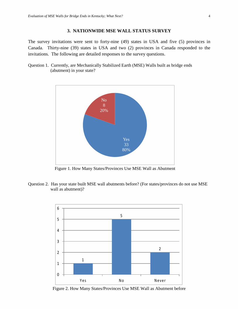
3. NATIONWIDE MSE WALL STATUS SURVEY The survey invitations were sent to forty-nine (49) states in USA and five (5) provinces in Canada. Thirty-nine (39) states in USA and two (2) provinces in Canada responded to the invitations. The following are detailed responses to the survey questions. Question 1. Currently, are Mechanically Stabilized Earth (MSE) Walls built as bridge ends
(abutment) in your state?
Question 2. Has your state built MSE wall abutments before? (For states/provinces do not use MSE
wall as abutment)?
Figure 1. How Many States/Provinces Use MSE Wall as Abutment
Yes33
80%
No8
20%
Figure 2. How Many States/Provinces Use MSE Wall as Abutment before
1
5
2
0
1
2
3
4
5
6
Y e s N o N e ve r
Evaluation of MSE Walls for Bridge Ends in Kentucky; What Next?
5
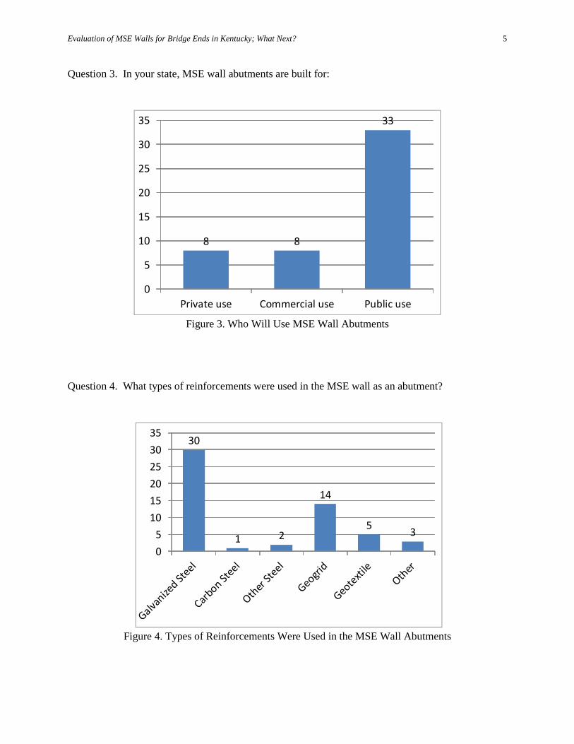
Question 3. In your state, MSE wall abutments are built for:
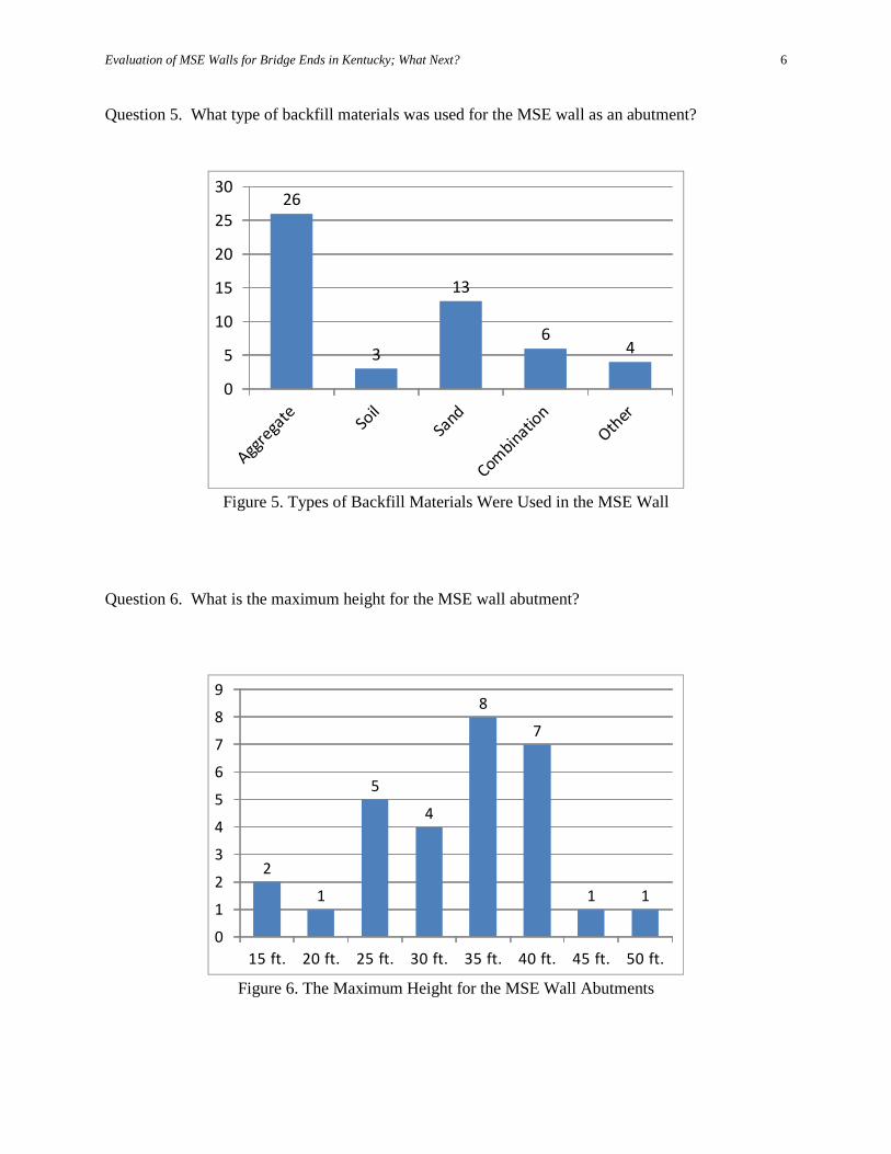
Question 4. What types of reinforcements were used in the MSE wall as an abutment?
Figure 3. Who Will Use MSE Wall Abutments
8 8
33
0
5
10
15
20
25
30
35
Private use Commercial use Public use
Figure 4. Types of Reinforcements Were Used in the MSE Wall Abutments
30
1 2
14
5 3
05
101520253035
Evaluation of MSE Walls for Bridge Ends in Kentucky; What Next?
6
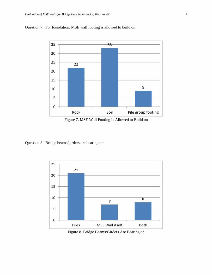
Question 5. What type of backfill materials was used for the MSE wall as an abutment?
Question 6. What is the maximum height for the MSE wall abutment?
Figure 5. Types of Backfill Materials Were Used in the MSE Wall
26
3
13
64
0
5
10
15
20
25
30
Figure 6. The Maximum Height for the MSE Wall Abutments
2
1
5
4
8
7
1 1
0
1
2
3
4
5
6
7
8
9
15 ft. 20 ft. 25 ft. 30 ft. 35 ft. 40 ft. 45 ft. 50 ft.
Evaluation of MSE Walls for Bridge Ends in Kentucky; What Next?
7
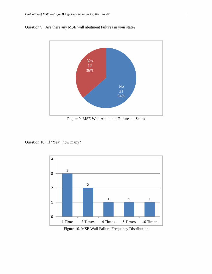
Question 7. For foundation, MSE wall footing is allowed to build on:
Question 8. Bridge beams/girders are bearing on:
Figure 7. MSE Wall Footing Is Allowed to Build on
22
33
9
0
5
10
15
20
25
30
35
Rock Soil Pile group footing
Figure 8. Bridge Beams/Girders Are Bearing on
21
7 8
0
5
10
15
20
25
Piles MSE Wall itself Both
Evaluation of MSE Walls for Bridge Ends in Kentucky; What Next?
8
Question 9. Are there any MSE wall abutment failures in your state?
Question 10. If "Yes", how many?
Figure 9. MSE Wall Abutment Failures in States
No21
64%
Yes12
36%
Figure 10. MSE Wall Failure Frequency Distribution
3
2
1 1 1
0
1
2
3
4
1 Time 2 Times 4 Times 5 Times 10 Times
Evaluation of MSE Walls for Bridge Ends in Kentucky; What Next?
9
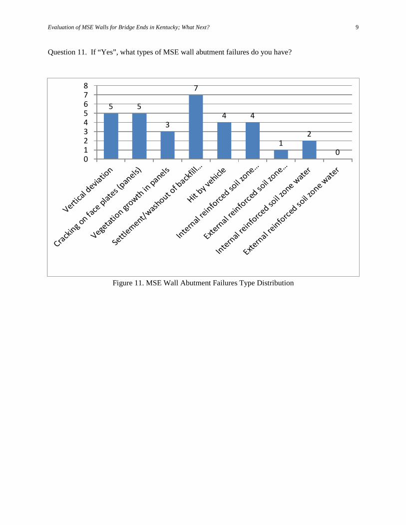
Question 11. If “Yes”, what types of MSE wall abutment failures do you have?
Figure 11. MSE Wall Abutment Failures Type Distribution
5 5
3
7
4 4
12
0012345678
Evaluation of MSE Walls for Bridge Ends in Kentucky; What Next?
10
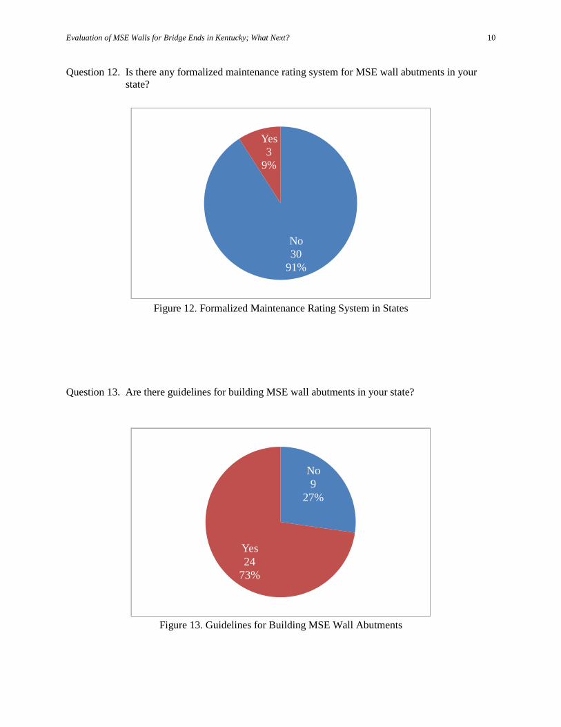
Question 12. Is there any formalized maintenance rating system for MSE wall abutments in your state?
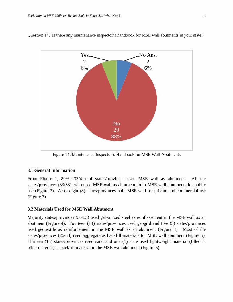
Question 13. Are there guidelines for building MSE wall abutments in your state?
Figure 12. Formalized Maintenance Rating System in States
No30
91%
Yes3
9%
Figure 13. Guidelines for Building MSE Wall Abutments
No9
27%
Yes24
73%
Evaluation of MSE Walls for Bridge Ends in Kentucky; What Next?
11
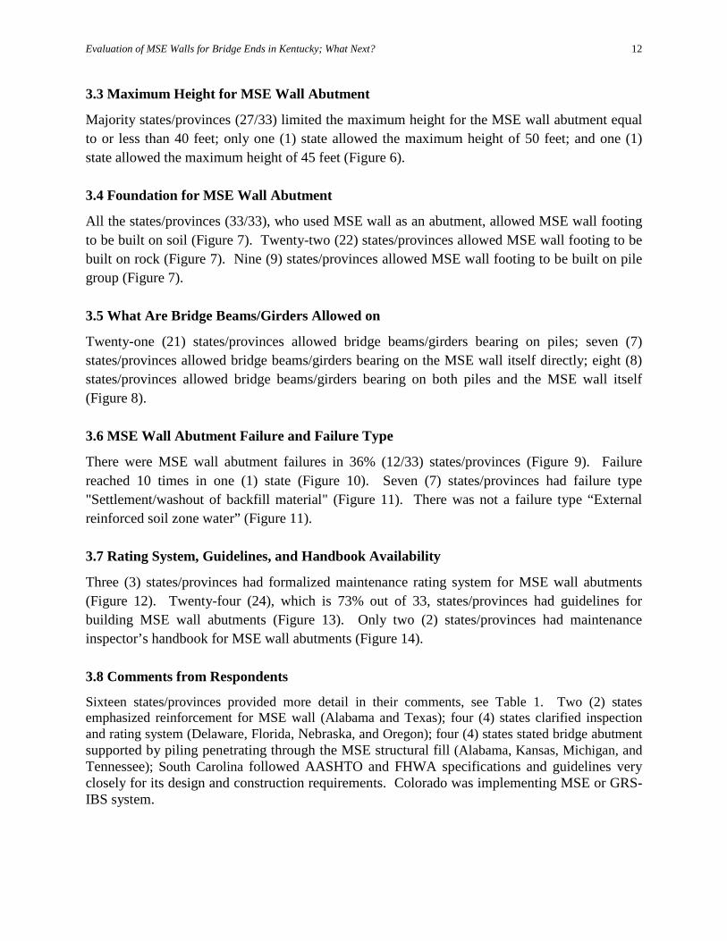
Question 14. Is there any maintenance inspector’s handbook for MSE wall abutments in your state?
3.1 General Information
From Figure 1, 80% (33/41) of states/provinces used MSE wall as abutment. All the states/provinces (33/33), who used MSE wall as abutment, built MSE wall abutments for public use (Figure 3). Also, eight (8) states/provinces built MSE wall for private and commercial use (Figure 3). 3.2 Materials Used for MSE Wall Abutment
Majority states/provinces (30/33) used galvanized steel as reinforcement in the MSE wall as an abutment (Figure 4). Fourteen (14) states/provinces used geogrid and five (5) states/provinces used geotextile as reinforcement in the MSE wall as an abutment (Figure 4). Most of the states/provinces (26/33) used aggregate as backfill materials for MSE wall abutment (Figure 5). Thirteen (13) states/provinces used sand and one (1) state used lightweight material (filled in other material) as backfill material in the MSE wall abutment (Figure 5).
Figure 14. Maintenance Inspector’s Handbook for MSE Wall Abutments
No Ans.2
6%
No29
88%
Yes2
6%
Evaluation of MSE Walls for Bridge Ends in Kentucky; What Next?
12
3.3 Maximum Height for MSE Wall Abutment
Majority states/provinces (27/33) limited the maximum height for the MSE wall abutment equal to or less than 40 feet; only one (1) state allowed the maximum height of 50 feet; and one (1) state allowed the maximum height of 45 feet (Figure 6). 3.4 Foundation for MSE Wall Abutment
All the states/provinces (33/33), who used MSE wall as an abutment, allowed MSE wall footing to be built on soil (Figure 7). Twenty-two (22) states/provinces allowed MSE wall footing to be built on rock (Figure 7). Nine (9) states/provinces allowed MSE wall footing to be built on pile group (Figure 7). 3.5 What Are Bridge Beams/Girders Allowed on
Twenty-one (21) states/provinces allowed bridge beams/girders bearing on piles; seven (7) states/provinces allowed bridge beams/girders bearing on the MSE wall itself directly; eight (8) states/provinces allowed bridge beams/girders bearing on both piles and the MSE wall itself (Figure 8). 3.6 MSE Wall Abutment Failure and Failure Type
There were MSE wall abutment failures in 36% (12/33) states/provinces (Figure 9). Failure reached 10 times in one (1) state (Figure 10). Seven (7) states/provinces had failure type "Settlement/washout of backfill material" (Figure 11). There was not a failure type “External reinforced soil zone water” (Figure 11). 3.7 Rating System, Guidelines, and Handbook Availability
Three (3) states/provinces had formalized maintenance rating system for MSE wall abutments (Figure 12). Twenty-four (24), which is 73% out of 33, states/provinces had guidelines for building MSE wall abutments (Figure 13). Only two (2) states/provinces had maintenance inspector’s handbook for MSE wall abutments (Figure 14). 3.8 Comments from Respondents
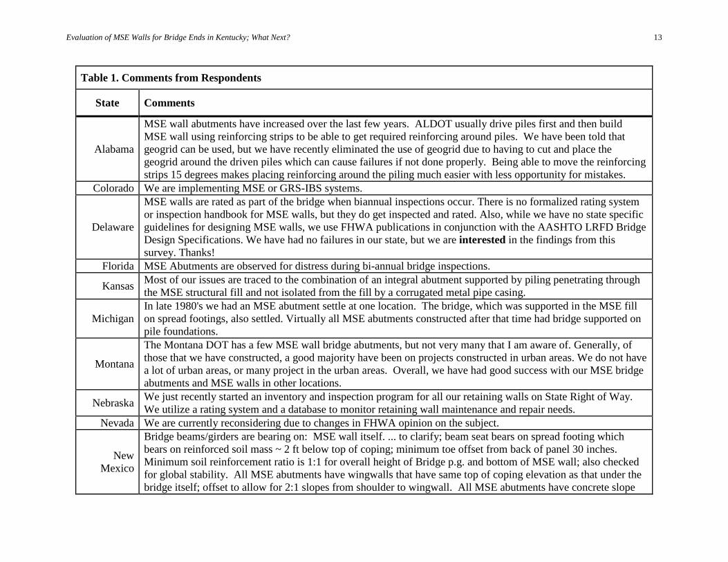
Sixteen states/provinces provided more detail in their comments, see Table 1. Two (2) states emphasized reinforcement for MSE wall (Alabama and Texas); four (4) states clarified inspection and rating system (Delaware, Florida, Nebraska, and Oregon); four (4) states stated bridge abutment supported by piling penetrating through the MSE structural fill (Alabama, Kansas, Michigan, and Tennessee); South Carolina followed AASHTO and FHWA specifications and guidelines very closely for its design and construction requirements. Colorado was implementing MSE or GRS-IBS system.
Evaluation of MSE Walls for Bridge Ends in Kentucky; What Next?
13
Table 1. Comments from Respondents
State Comments
Alabama
MSE wall abutments have increased over the last few years. ALDOT usually drive piles first and then build MSE wall using reinforcing strips to be able to get required reinforcing around piles. We have been told that geogrid can be used, but we have recently eliminated the use of geogrid due to having to cut and place the geogrid around the driven piles which can cause failures if not done properly. Being able to move the reinforcing strips 15 degrees makes placing reinforcing around the piling much easier with less opportunity for mistakes.
Colorado We are implementing MSE or GRS-IBS systems.
Delaware
MSE walls are rated as part of the bridge when biannual inspections occur. There is no formalized rating system or inspection handbook for MSE walls, but they do get inspected and rated. Also, while we have no state specific guidelines for designing MSE walls, we use FHWA publications in conjunction with the AASHTO LRFD Bridge Design Specifications. We have had no failures in our state, but we are interested in the findings from this survey. Thanks!
Florida MSE Abutments are observed for distress during bi-annual bridge inspections.
Kansas Most of our issues are traced to the combination of an integral abutment supported by piling penetrating through the MSE structural fill and not isolated from the fill by a corrugated metal pipe casing.
Michigan In late 1980's we had an MSE abutment settle at one location. The bridge, which was supported in the MSE fill on spread footings, also settled. Virtually all MSE abutments constructed after that time had bridge supported on pile foundations.
Montana
The Montana DOT has a few MSE wall bridge abutments, but not very many that I am aware of. Generally, of those that we have constructed, a good majority have been on projects constructed in urban areas. We do not have a lot of urban areas, or many project in the urban areas. Overall, we have had good success with our MSE bridge abutments and MSE walls in other locations.
Nebraska We just recently started an inventory and inspection program for all our retaining walls on State Right of Way. We utilize a rating system and a database to monitor retaining wall maintenance and repair needs.
Nevada We are currently reconsidering due to changes in FHWA opinion on the subject.
New Mexico
Bridge beams/girders are bearing on: MSE wall itself. ... to clarify; beam seat bears on spread footing which bears on reinforced soil mass ~ 2 ft below top of coping; minimum toe offset from back of panel 30 inches. Minimum soil reinforcement ratio is 1:1 for overall height of Bridge p.g. and bottom of MSE wall; also checked for global stability. All MSE abutments have wingwalls that have same top of coping elevation as that under the bridge itself; offset to allow for 2:1 slopes from shoulder to wingwall. All MSE abutments have concrete slope
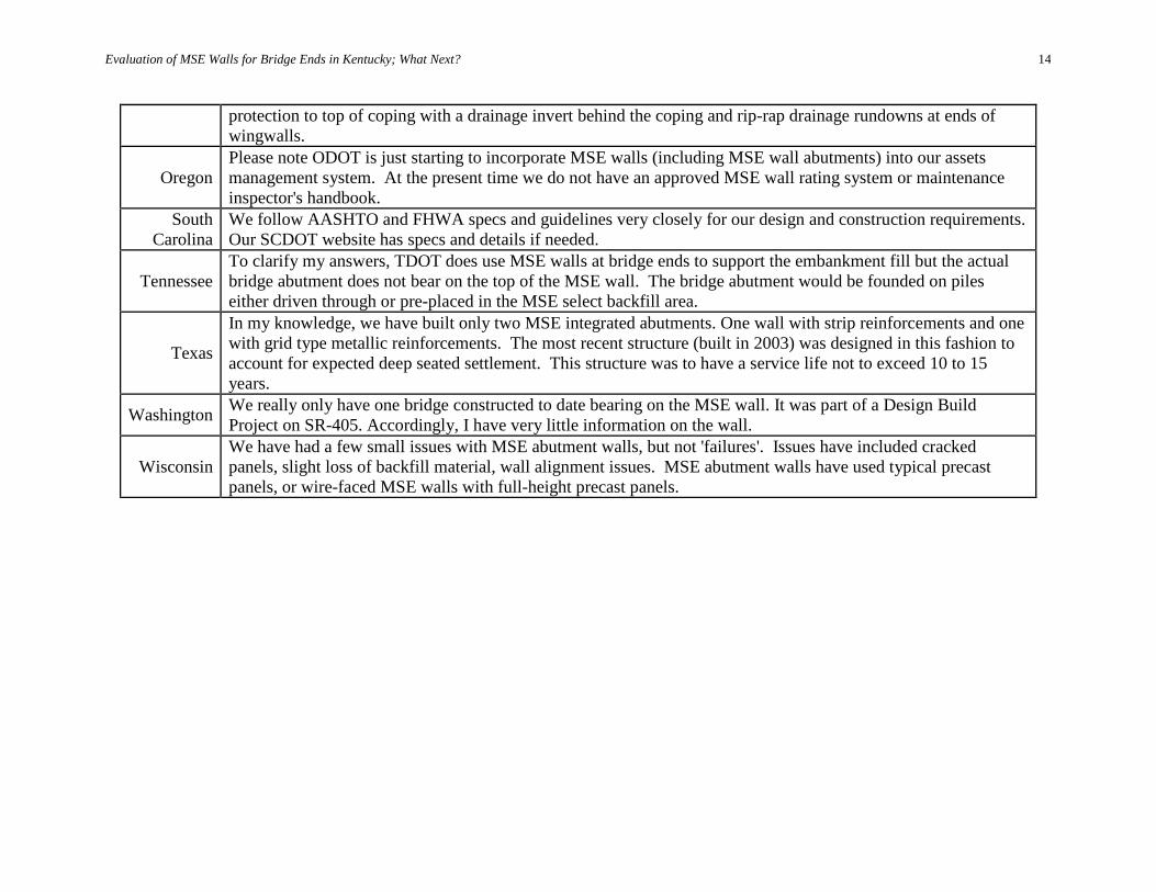
Evaluation of MSE Walls for Bridge Ends in Kentucky; What Next?
14
protection to top of coping with a drainage invert behind the coping and rip-rap drainage rundowns at ends of wingwalls.
Oregon Please note ODOT is just starting to incorporate MSE walls (including MSE wall abutments) into our assets management system. At the present time we do not have an approved MSE wall rating system or maintenance inspector's handbook.
South Carolina
We follow AASHTO and FHWA specs and guidelines very closely for our design and construction requirements. Our SCDOT website has specs and details if needed.
Tennessee To clarify my answers, TDOT does use MSE walls at bridge ends to support the embankment fill but the actual bridge abutment does not bear on the top of the MSE wall. The bridge abutment would be founded on piles either driven through or pre-placed in the MSE select backfill area.
Texas
In my knowledge, we have built only two MSE integrated abutments. One wall with strip reinforcements and one with grid type metallic reinforcements. The most recent structure (built in 2003) was designed in this fashion to account for expected deep seated settlement. This structure was to have a service life not to exceed 10 to 15 years.
Washington We really only have one bridge constructed to date bearing on the MSE wall. It was part of a Design Build Project on SR-405. Accordingly, I have very little information on the wall.
Wisconsin We have had a few small issues with MSE abutment walls, but not 'failures'. Issues have included cracked panels, slight loss of backfill material, wall alignment issues. MSE abutment walls have used typical precast panels, or wire-faced MSE walls with full-height precast panels.
Evaluation of MSE Walls for Bridge Ends in Kentucky; What Next?
15
4. MSE WALL ABUTMENT CONDITION RATING WEB APPLICATION To aid in the rating process for maintenance, a web application for the MSE Wall Abutment Inspection/Rating In KY has been developed in this study. Some handy features such as sharing pictures and files on line, and showing sites on Google map, drilling down to specific locations for details from map point were built into this application. A link from MSE wall rating web application to KYTC Geotechnical Report Database was created. It was decided that it was convenient for user to get correct geotechnical report corresponding to the current job site. Corresponding shop drawings or as-built plans were uploaded to the MSE wall rating web application as well. In this preliminary stage, only following visual rating system was adopted:
• Excellent - MSE wall abutment is in perfect condition without any visible damage/deterioration/deformation; without big vegetation protruding from face.
• Good - MSE wall abutment is in good condition with small visible damage/deterioration/deformation; or with big vegetation protruding from face.
• Fair - There are non-ignorable visible damage/deterioration/deformation on MSE wall abutment and need to pay big attention on it.
• Poor - There are significant visible damage/deterioration/deformation on MSE wall abutment and need to fix ASAP; otherwise, it will threaten public traffic.
Similar to National Bridge Inventory (NBI) rating system for bridge decks, superstructures, and substructures, the point rating system like the following can be fulfilled in this MSE wall abutment rating web application if it is needed:
• 9 - Superior to present desirable criteria • 8 - Equal to present desirable criteria • 7 - Better than present minimum criteria • 6 - Equal to present minimum criteria • 5 - Somewhat better than minimum adequacy to tolerate being left in place as is • 4 - Meets minimum tolerable limits to be left in place as is • 3 - Basically intolerable requiring high priority of corrective action • 2 - Basically intolerable requiring high priority of replacement • 1 - This value of rating code not used • 0 - Bridge closed
It is anticipated that there will be two primary users of MSE Wall Abutment Inspection/Rating In KY web application; principal investigators and project administrators. There also will be non-registered viewers. These viewers will have permission to view only the
Evaluation of MSE Walls for Bridge Ends in Kentucky; What Next?
16
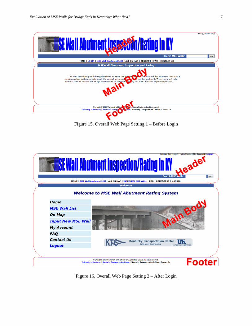
available information, not to add or edit the data. The primary users will be responsible for maintaining and updating MSE Wall Abutment Inspection/Rating In KY web application with data determined from site location, inspection results, and monitoring the history of a MSE wall abutment while viewers will only be allowed to “view” the information about MSE wall abutments. In efforts to assist users of MSE Wall Abutment Inspection/Rating In KY web application the following will highlight the web features. Various graphical user interfaces of the web application are illustrated and described below. 4.1 Overall Web Page Setting For the user’s convenience, all the functioning web pages on MSE Wall Abutment Inspection/Rating In KY web application are divided to three parts which are Header, Main Body, and Footer (Figures 15 and 16). The header portion has two different settings for before and after Login. The common contents include web title, date, Search MSE Walls and “go”. It also includes links to: Home, MSE Wall Abutment List, All on Map, FAQ, and Contact Us. Before Login, there are links to Login and Register. After Login, user’s first name will be shown on the top line; link to My Account provides page for modifying user’s own information; Logout is always shown on top right corner; Input New MSE wall leads user to the page to provide MSE wall abutment Information. If the user is an agency, Input New MSE wall link will not show up. If the user is an administrator, User Administration is a special link for her/him. User Administration provides a page to maintain all the users registered to MSE Wall Abutment Inspection/Rating In KY web application. The Main Body is the area to host different functioning pages, which will be illustrated in detail later. The Footer provides links to related web sites such as University of Kentucky, Kentucky Transportation Center, Kentucky Transportation Cabinet, and Contact Us. They are handy for all the users.
Evaluation of MSE Walls for Bridge Ends in Kentucky; What Next?
17
Figure 15. Overall Web Page Setting 1 – Before Login
Figure 16. Overall Web Page Setting 2 – After Login
Evaluation of MSE Walls for Bridge Ends in Kentucky; What Next?
18
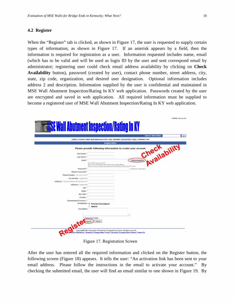
4.2 Register When the “Register” tab is clicked, as shown in Figure 17, the user is requested to supply certain types of information, as shown in Figure 17. If an asterisk appears by a field, then the information is required for registration as a user. Information requested includes name, email (which has to be valid and will be used as login ID by the user and sent correspond email by administrator; registering user could check email address availability by clicking on Check Availability button), password (created by user), contact phone number, street address, city, state, zip code, organization, and desired user designation. Optional information includes address 2 and description. Information supplied by the user is confidential and maintained in MSE Wall Abutment Inspection/Rating In KY web application. Passwords created by the user are encrypted and saved in web application. All required information must be supplied to become a registered user of MSE Wall Abutment Inspection/Rating In KY web application.
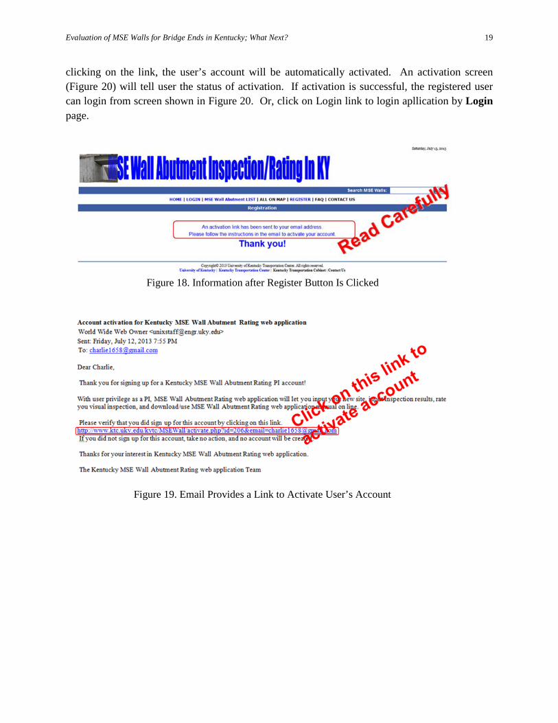
After the user has entered all the required information and clicked on the Register button, the following screen (Figure 18) appears. It tells the user: “An activation link has been sent to your email address. Please follow the instructions in the email to activate your account.” By checking the submitted email, the user will find an email similar to one shown in Figure 19. By
Figure 17. Registration Screen
Evaluation of MSE Walls for Bridge Ends in Kentucky; What Next?
19
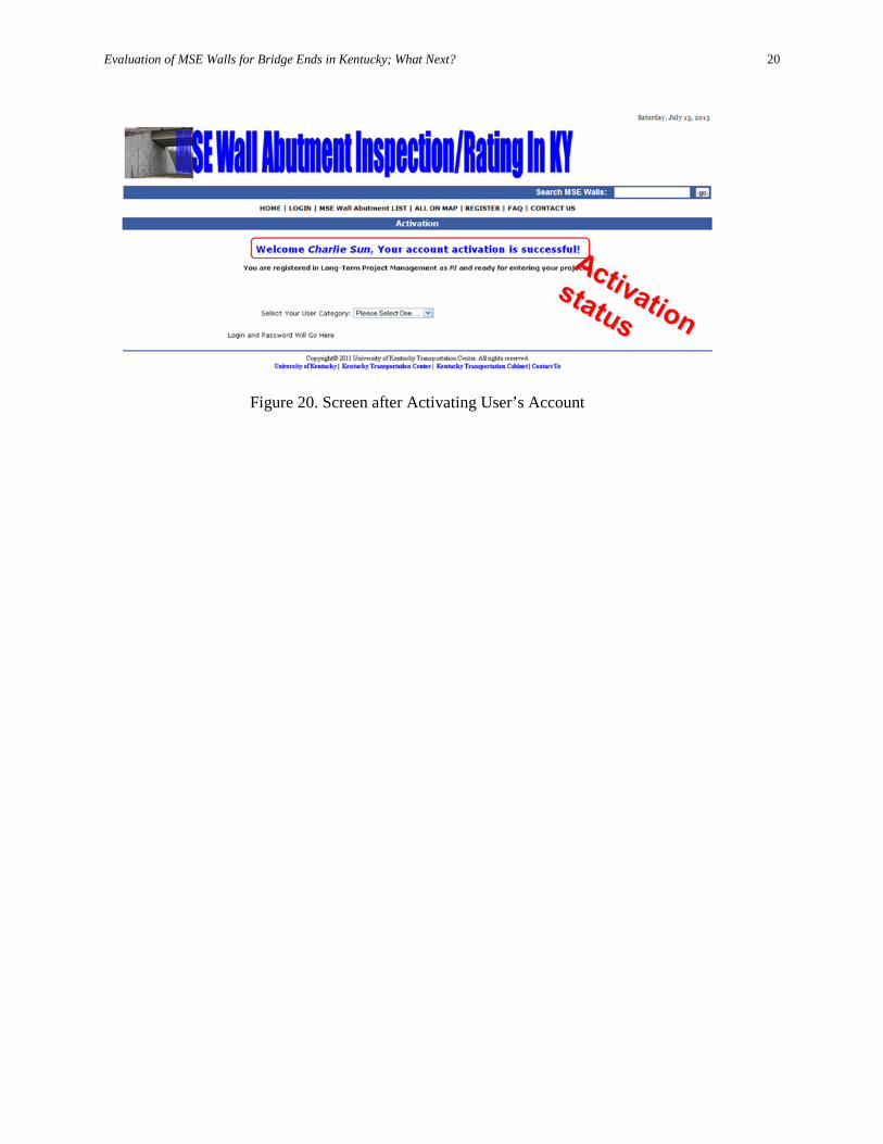
clicking on the link, the user’s account will be automatically activated. An activation screen (Figure 20) will tell user the status of activation. If activation is successful, the registered user can login from screen shown in Figure 20. Or, click on Login link to login apllication by Login page.
Figure 18. Information after Register Button Is Clicked
Figure 19. Email Provides a Link to Activate User’s Account
Evaluation of MSE Walls for Bridge Ends in Kentucky; What Next?
20
Figure 20. Screen after Activating User’s Account
Evaluation of MSE Walls for Bridge Ends in Kentucky; What Next?
21
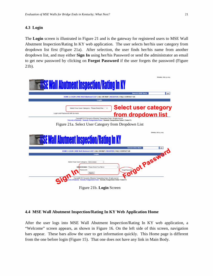
4.3 Login The Login screen is illustrated in Figure 21 and is the gateway for registered users to MSE Wall Abutment Inspection/Rating In KY web application. The user selects her/his user category from dropdown list first (Figure 21a). After selection, the user finds her/his name from another dropdown list, and may either Sign In using her/his Password or send the administrator an email to get new password by clicking on Forgot Password if the user forgets the password (Figure 21b).
4.4 MSE Wall Abutment Inspection/Rating In KY Web Application Home After the user logs into MSE Wall Abutment Inspection/Rating In KY web application, a “Welcome” screen appears, as shown in Figure 16. On the left side of this screen, navigation bars appear. These bars allow the user to get information quickly. This Home page is different from the one before login (Figure 15). That one does not have any link in Main Body.
Figure 21a. Select User Category from Dropdown List
Figure 21b. Login Screen
Evaluation of MSE Walls for Bridge Ends in Kentucky; What Next?
22
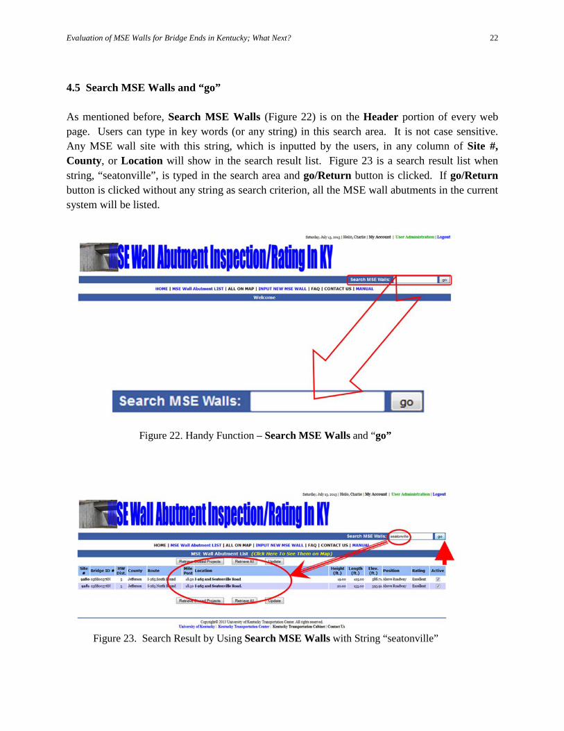
4.5 Search MSE Walls and “go” As mentioned before, Search MSE Walls (Figure 22) is on the Header portion of every web page. Users can type in key words (or any string) in this search area. It is not case sensitive. Any MSE wall site with this string, which is inputted by the users, in any column of Site #, County, or Location will show in the search result list. Figure 23 is a search result list when string, “seatonville”, is typed in the search area and go/Return button is clicked. If go/Return button is clicked without any string as search criterion, all the MSE wall abutments in the current system will be listed.
Figure 22. Handy Function – Search MSE Walls and “go”
Figure 23. Search Result by Using Search MSE Walls with String “seatonville”
Evaluation of MSE Walls for Bridge Ends in Kentucky; What Next?
23
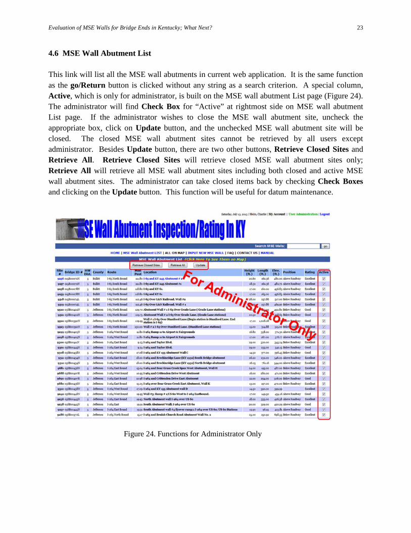
4.6 MSE Wall Abutment List This link will list all the MSE wall abutments in current web application. It is the same function as the go/Return button is clicked without any string as a search criterion. A special column, Active, which is only for administrator, is built on the MSE wall abutment List page (Figure 24). The administrator will find Check Box for “Active” at rightmost side on MSE wall abutment List page. If the administrator wishes to close the MSE wall abutment site, uncheck the appropriate box, click on Update button, and the unchecked MSE wall abutment site will be closed. The closed MSE wall abutment sites cannot be retrieved by all users except administrator. Besides Update button, there are two other buttons, Retrieve Closed Sites and Retrieve All. Retrieve Closed Sites will retrieve closed MSE wall abutment sites only; Retrieve All will retrieve all MSE wall abutment sites including both closed and active MSE wall abutment sites. The administrator can take closed items back by checking Check Boxes and clicking on the Update button. This function will be useful for datum maintenance.
Figure 24. Functions for Administrator Only
Evaluation of MSE Walls for Bridge Ends in Kentucky; What Next?
24
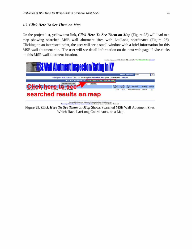
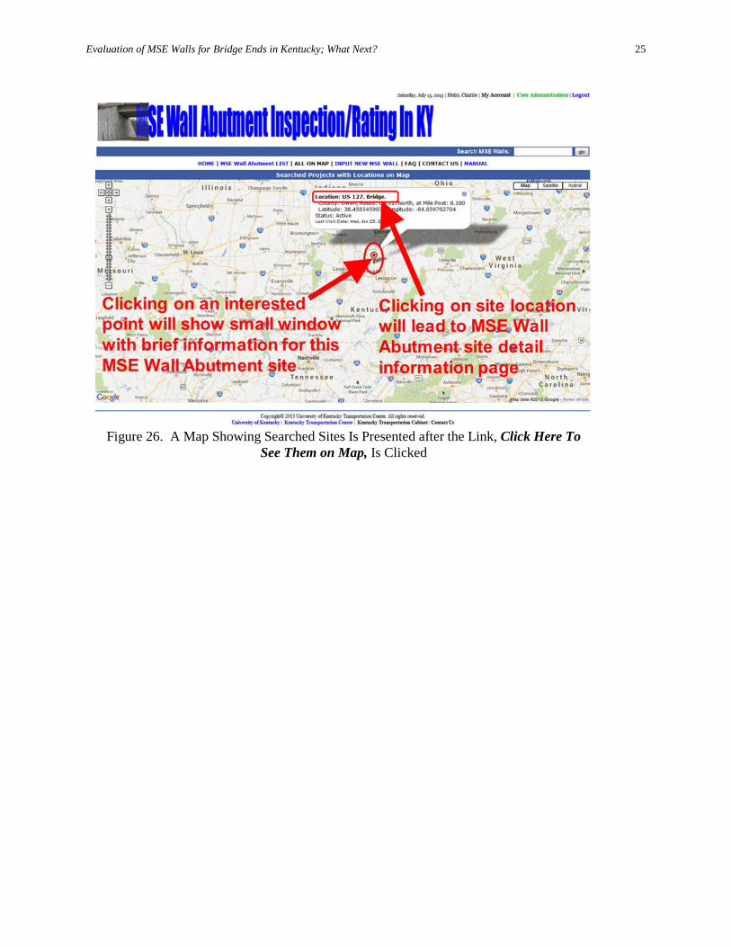
4.7 Click Here To See Them on Map On the project list, yellow text link, Click Here To See Them on Map (Figure 25) will lead to a map showing searched MSE wall abutment sites with Lat/Long coordinates (Figure 26). Clicking on an interested point, the user will see a small window with a brief information for this MSE wall abutment site. The user will see detail information on the next web page if s/he clicks on this MSE wall abutment location.
Figure 25. Click Here To See Them on Map Shows Searched MSE Wall Abutment Sites,
Which Have Lat/Long Coordinates, on a Map
Evaluation of MSE Walls for Bridge Ends in Kentucky; What Next?
25
Figure 26. A Map Showing Searched Sites Is Presented after the Link, Click Here To
See Them on Map, Is Clicked
Evaluation of MSE Walls for Bridge Ends in Kentucky; What Next?
26
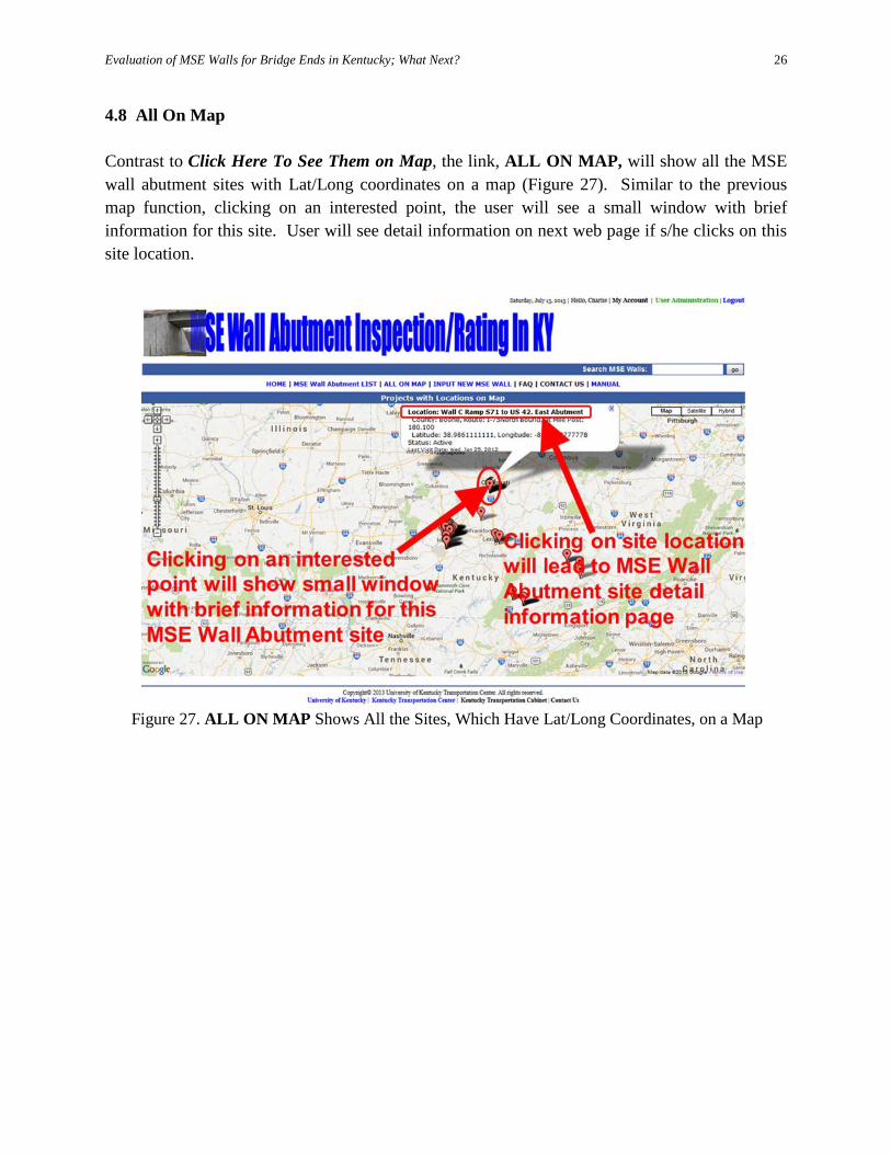
4.8 All On Map Contrast to Click Here To See Them on Map, the link, ALL ON MAP, will show all the MSE wall abutment sites with Lat/Long coordinates on a map (Figure 27). Similar to the previous map function, clicking on an interested point, the user will see a small window with brief information for this site. User will see detail information on next web page if s/he clicks on this site location.
Figure 27. ALL ON MAP Shows All the Sites, Which Have Lat/Long Coordinates, on a Map
Evaluation of MSE Walls for Bridge Ends in Kentucky; What Next?
27
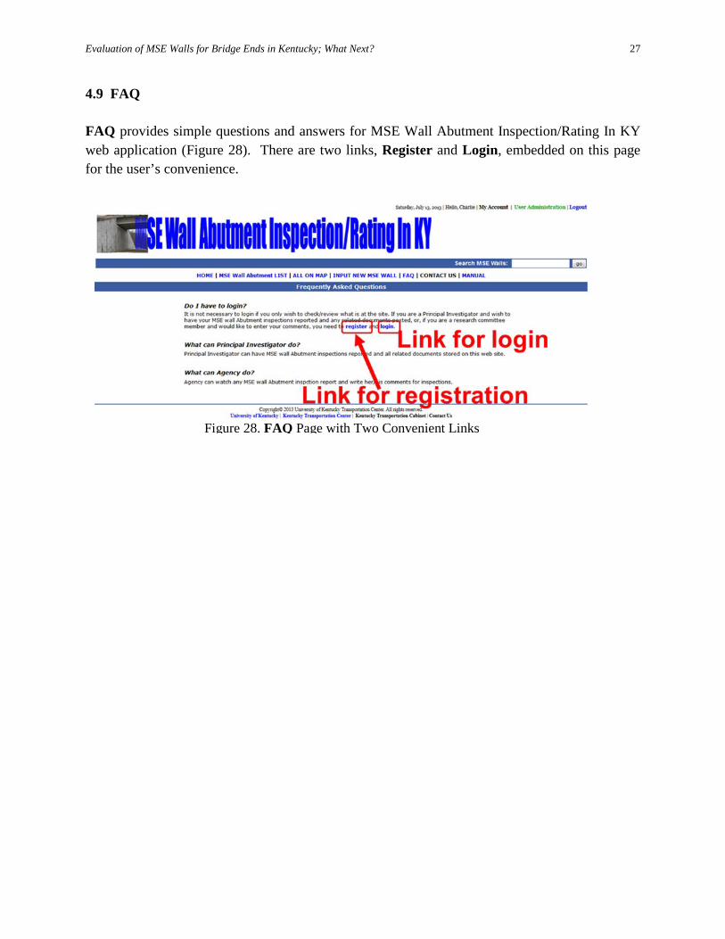
4.9 FAQ FAQ provides simple questions and answers for MSE Wall Abutment Inspection/Rating In KY web application (Figure 28). There are two links, Register and Login, embedded on this page for the user’s convenience.
Figure 28. FAQ Page with Two Convenient Links
Evaluation of MSE Walls for Bridge Ends in Kentucky; What Next?
28
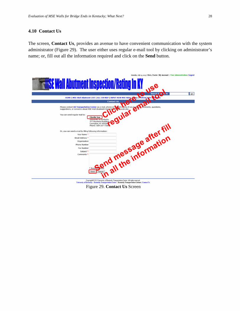
4.10 Contact Us The screen, Contact Us, provides an avenue to have convenient communication with the system administrator (Figure 29). The user either uses regular e-mail tool by clicking on administrator’s name; or, fill out all the information required and click on the Send button.
Figure 29. Contact Us Screen
Evaluation of MSE Walls for Bridge Ends in Kentucky; What Next?
29
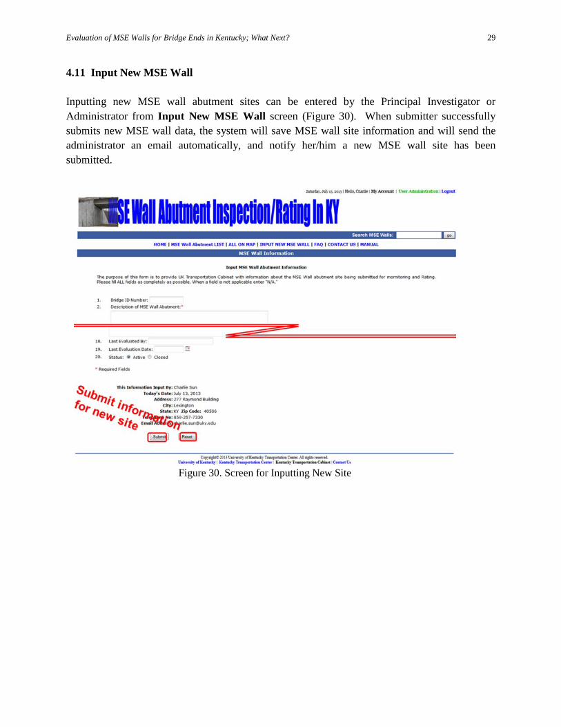
4.11 Input New MSE Wall Inputting new MSE wall abutment sites can be entered by the Principal Investigator or Administrator from Input New MSE Wall screen (Figure 30). When submitter successfully submits new MSE wall data, the system will save MSE wall site information and will send the administrator an email automatically, and notify her/him a new MSE wall site has been submitted.
Figure 30. Screen for Inputting New Site
Evaluation of MSE Walls for Bridge Ends in Kentucky; What Next?
30
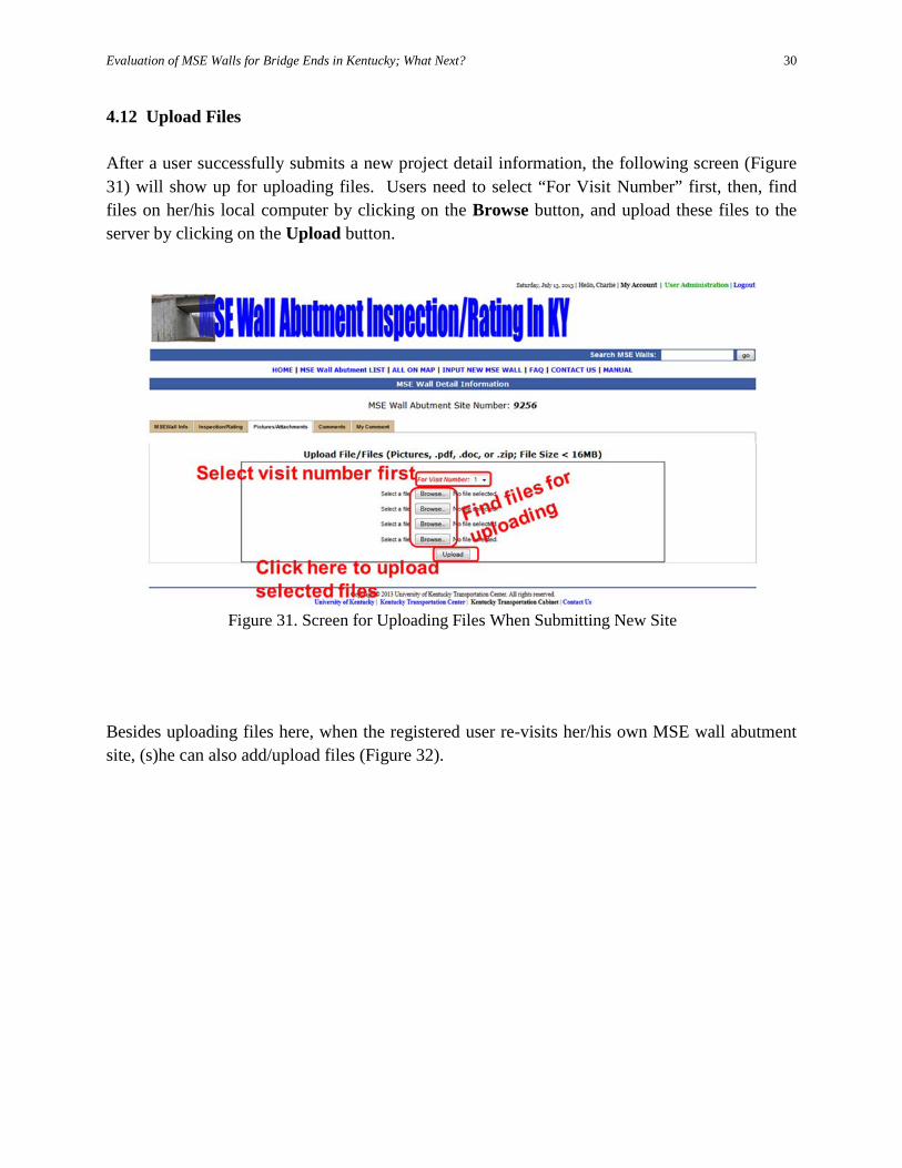
4.12 Upload Files After a user successfully submits a new project detail information, the following screen (Figure 31) will show up for uploading files. Users need to select “For Visit Number” first, then, find files on her/his local computer by clicking on the Browse button, and upload these files to the server by clicking on the Upload button.
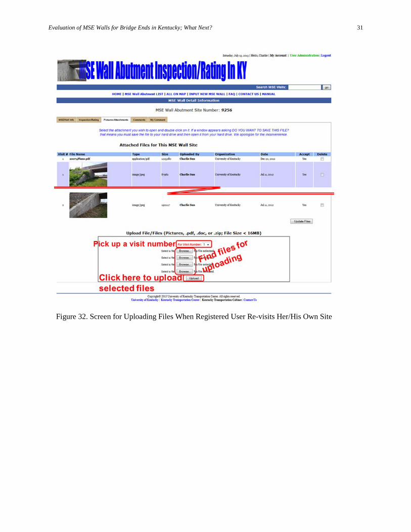
Besides uploading files here, when the registered user re-visits her/his own MSE wall abutment site, (s)he can also add/upload files (Figure 32).
Figure 31. Screen for Uploading Files When Submitting New Site
Evaluation of MSE Walls for Bridge Ends in Kentucky; What Next?
31
Figure 32. Screen for Uploading Files When Registered User Re-visits Her/His Own Site
Evaluation of MSE Walls for Bridge Ends in Kentucky; What Next?
32
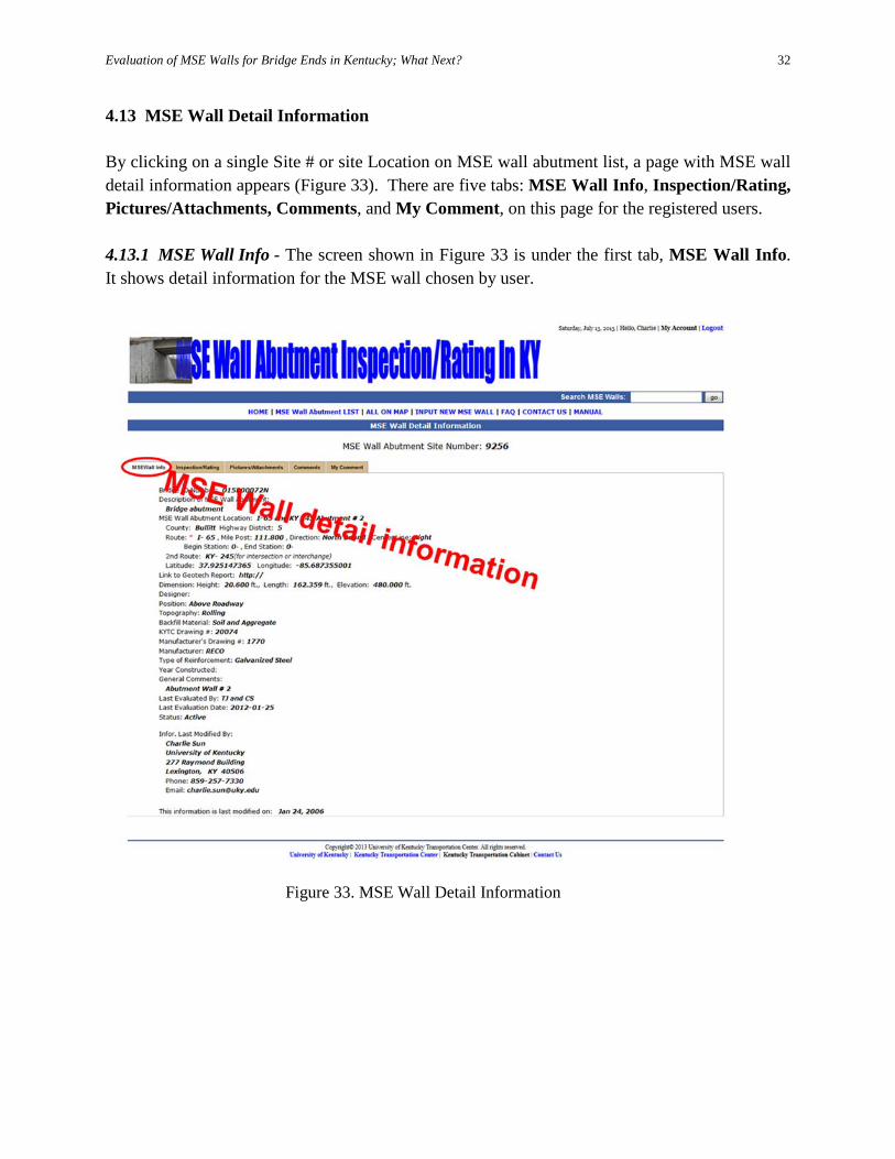
4.13 MSE Wall Detail Information By clicking on a single Site # or site Location on MSE wall abutment list, a page with MSE wall detail information appears (Figure 33). There are five tabs: MSE Wall Info, Inspection/Rating, Pictures/Attachments, Comments, and My Comment, on this page for the registered users. 4.13.1 MSE Wall Info - The screen shown in Figure 33 is under the first tab, MSE Wall Info. It shows detail information for the MSE wall chosen by user.
Figure 33. MSE Wall Detail Information
Evaluation of MSE Walls for Bridge Ends in Kentucky; What Next?
33
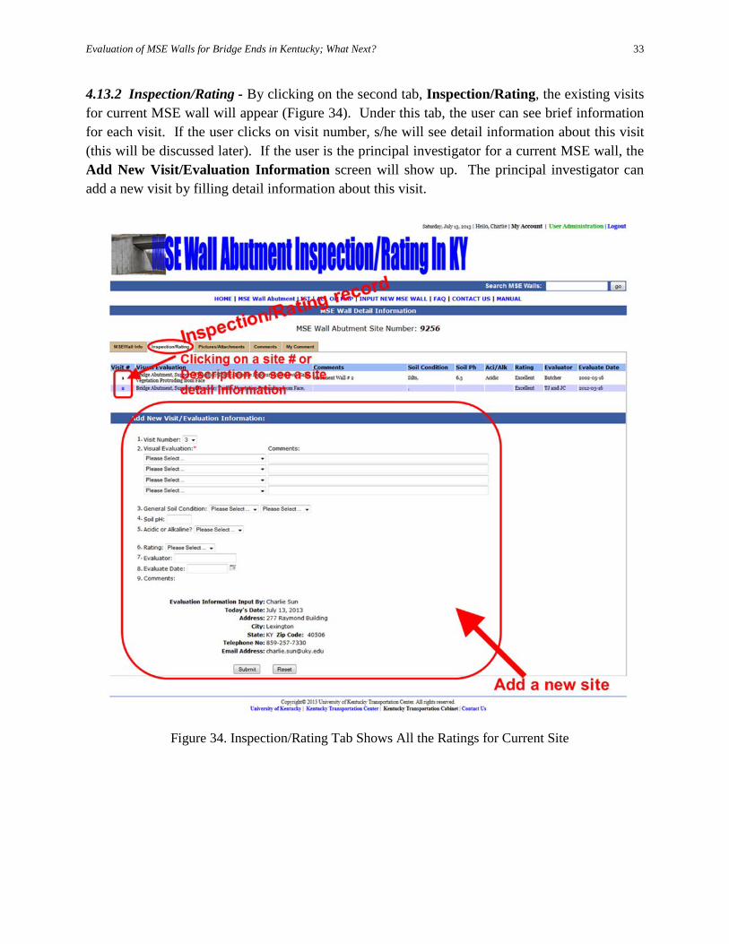
4.13.2 Inspection/Rating - By clicking on the second tab, Inspection/Rating, the existing visits for current MSE wall will appear (Figure 34). Under this tab, the user can see brief information for each visit. If the user clicks on visit number, s/he will see detail information about this visit (this will be discussed later). If the user is the principal investigator for a current MSE wall, the Add New Visit/Evaluation Information screen will show up. The principal investigator can add a new visit by filling detail information about this visit.
Figure 34. Inspection/Rating Tab Shows All the Ratings for Current Site
Evaluation of MSE Walls for Bridge Ends in Kentucky; What Next?
34
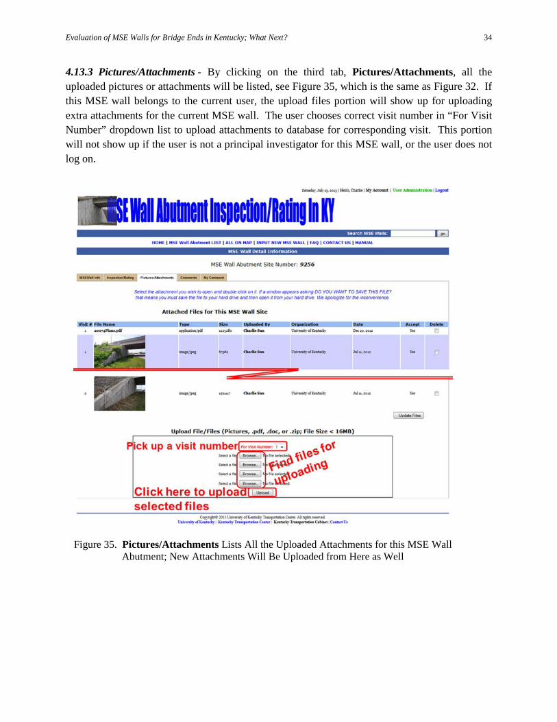
4.13.3 Pictures/Attachments - By clicking on the third tab, Pictures/Attachments, all the uploaded pictures or attachments will be listed, see Figure 35, which is the same as Figure 32. If this MSE wall belongs to the current user, the upload files portion will show up for uploading extra attachments for the current MSE wall. The user chooses correct visit number in “For Visit Number” dropdown list to upload attachments to database for corresponding visit. This portion will not show up if the user is not a principal investigator for this MSE wall, or the user does not log on.
Figure 35. Pictures/Attachments Lists All the Uploaded Attachments for this MSE Wall
Abutment; New Attachments Will Be Uploaded from Here as Well
Evaluation of MSE Walls for Bridge Ends in Kentucky; What Next?
35
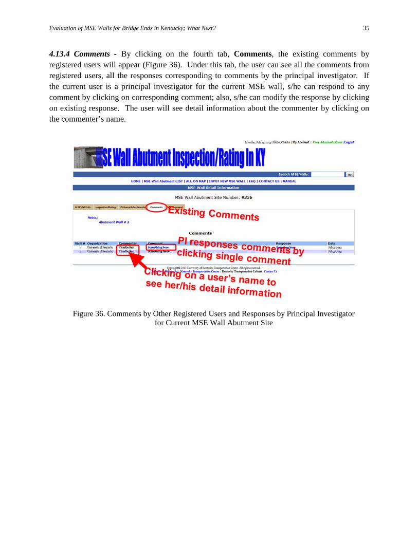
4.13.4 Comments - By clicking on the fourth tab, Comments, the existing comments by registered users will appear (Figure 36). Under this tab, the user can see all the comments from registered users, all the responses corresponding to comments by the principal investigator. If the current user is a principal investigator for the current MSE wall, s/he can respond to any comment by clicking on corresponding comment; also, s/he can modify the response by clicking on existing response. The user will see detail information about the commenter by clicking on the commenter’s name.
Figure 36. Comments by Other Registered Users and Responses by Principal Investigator
for Current MSE Wall Abutment Site
Evaluation of MSE Walls for Bridge Ends in Kentucky; What Next?
36
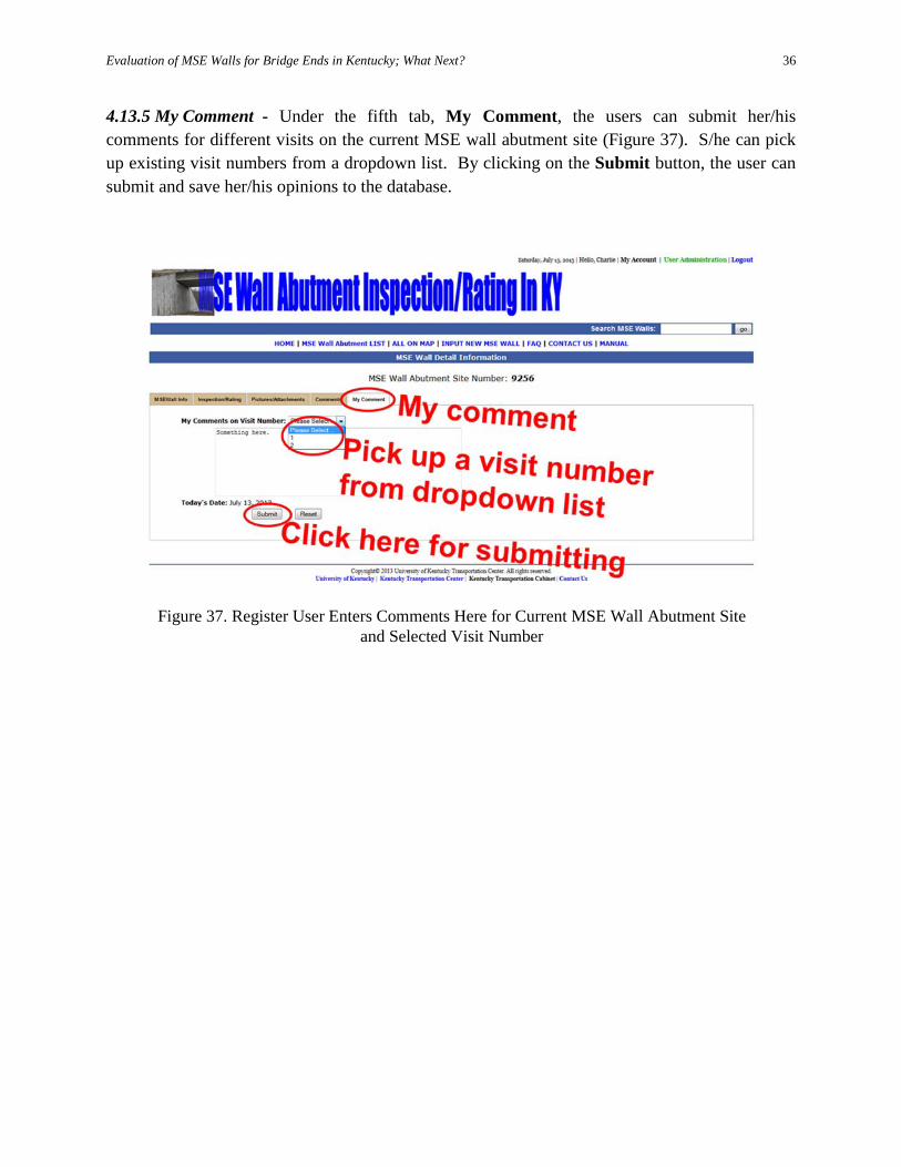
4.13.5 My Comment - Under the fifth tab, My Comment, the users can submit her/his comments for different visits on the current MSE wall abutment site (Figure 37). S/he can pick up existing visit numbers from a dropdown list. By clicking on the Submit button, the user can submit and save her/his opinions to the database.
Figure 37. Register User Enters Comments Here for Current MSE Wall Abutment Site and Selected Visit Number
Evaluation of MSE Walls for Bridge Ends in Kentucky; What Next?
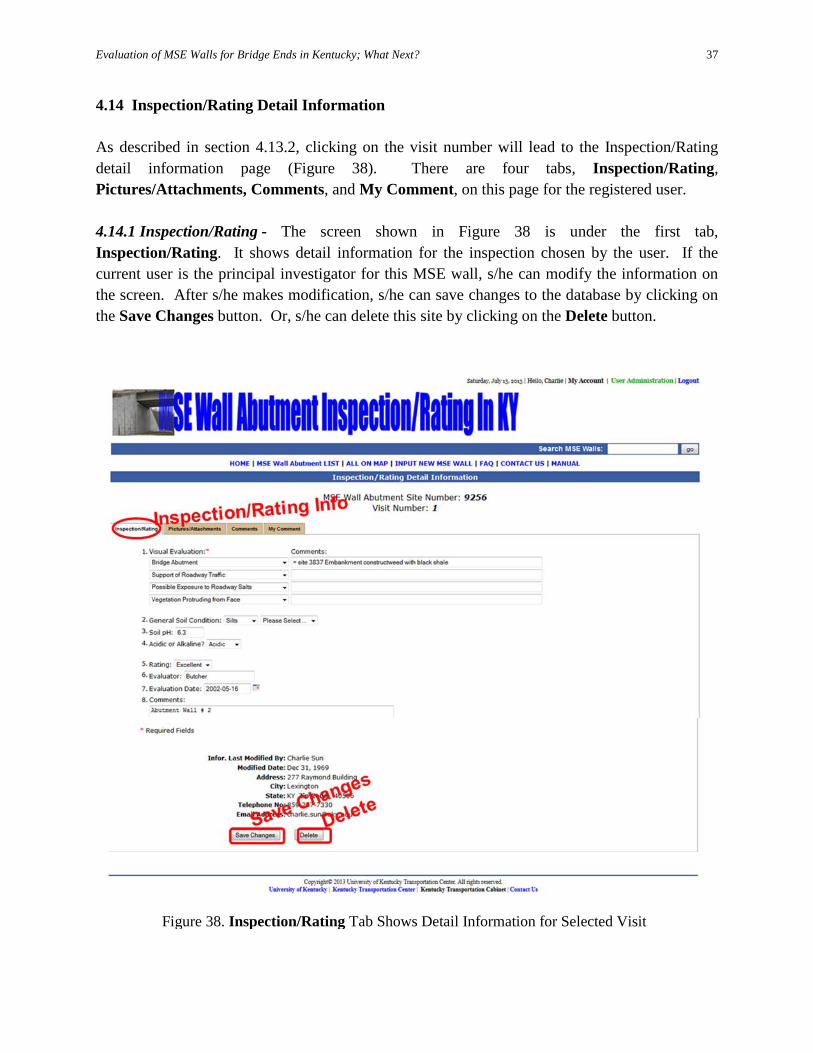
37
4.14 Inspection/Rating Detail Information As described in section 4.13.2, clicking on the visit number will lead to the Inspection/Rating detail information page (Figure 38). There are four tabs, Inspection/Rating, Pictures/Attachments, Comments, and My Comment, on this page for the registered user. 4.14.1 Inspection/Rating - The screen shown in Figure 38 is under the first tab, Inspection/Rating. It shows detail information for the inspection chosen by the user. If the current user is the principal investigator for this MSE wall, s/he can modify the information on the screen. After s/he makes modification, s/he can save changes to the database by clicking on the Save Changes button. Or, s/he can delete this site by clicking on the Delete button.
Figure 38. Inspection/Rating Tab Shows Detail Information for Selected Visit
Evaluation of MSE Walls for Bridge Ends in Kentucky; What Next?
38
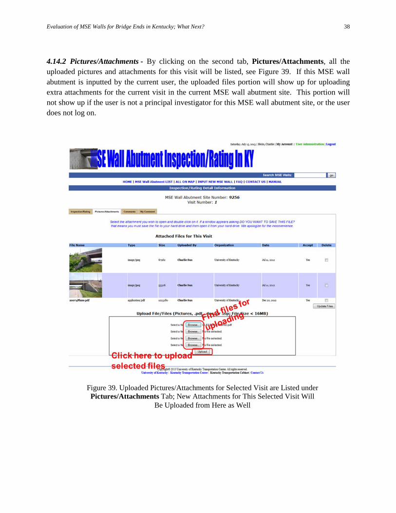
4.14.2 Pictures/Attachments - By clicking on the second tab, Pictures/Attachments, all the uploaded pictures and attachments for this visit will be listed, see Figure 39. If this MSE wall abutment is inputted by the current user, the uploaded files portion will show up for uploading extra attachments for the current visit in the current MSE wall abutment site. This portion will not show up if the user is not a principal investigator for this MSE wall abutment site, or the user does not log on.
Figure 39. Uploaded Pictures/Attachments for Selected Visit are Listed under Pictures/Attachments Tab; New Attachments for This Selected Visit Will
Be Uploaded from Here as Well
Evaluation of MSE Walls for Bridge Ends in Kentucky; What Next?
39
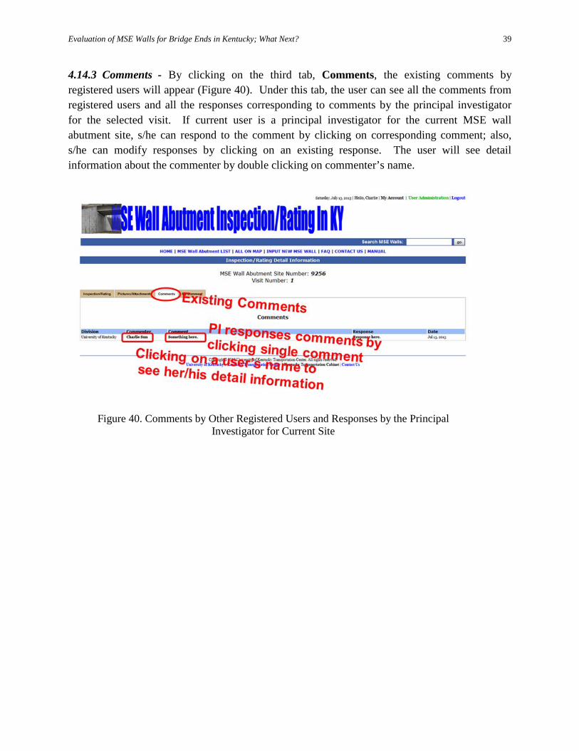
4.14.3 Comments - By clicking on the third tab, Comments, the existing comments by registered users will appear (Figure 40). Under this tab, the user can see all the comments from registered users and all the responses corresponding to comments by the principal investigator for the selected visit. If current user is a principal investigator for the current MSE wall abutment site, s/he can respond to the comment by clicking on corresponding comment; also, s/he can modify responses by clicking on an existing response. The user will see detail information about the commenter by double clicking on commenter’s name.
Figure 40. Comments by Other Registered Users and Responses by the Principal Investigator for Current Site
Evaluation of MSE Walls for Bridge Ends in Kentucky; What Next?
40
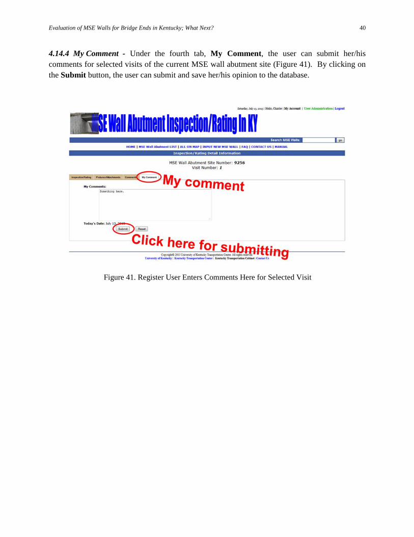
4.14.4 My Comment - Under the fourth tab, My Comment, the user can submit her/his comments for selected visits of the current MSE wall abutment site (Figure 41). By clicking on the Submit button, the user can submit and save her/his opinion to the database.
Figure 41. Register User Enters Comments Here for Selected Visit
Evaluation of MSE Walls for Bridge Ends in Kentucky; What Next?
41
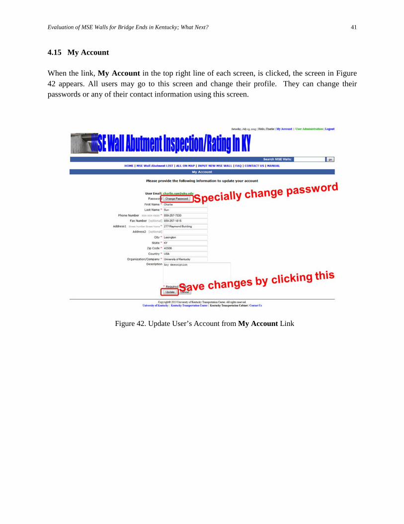
4.15 My Account When the link, My Account in the top right line of each screen, is clicked, the screen in Figure 42 appears. All users may go to this screen and change their profile. They can change their passwords or any of their contact information using this screen.
Figure 42. Update User’s Account from My Account Link
Evaluation of MSE Walls for Bridge Ends in Kentucky; What Next?
42
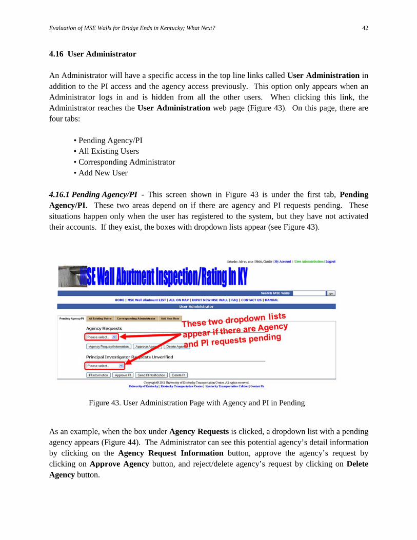
4.16 User Administrator An Administrator will have a specific access in the top line links called User Administration in addition to the PI access and the agency access previously. This option only appears when an Administrator logs in and is hidden from all the other users. When clicking this link, the Administrator reaches the User Administration web page (Figure 43). On this page, there are four tabs:
• Pending Agency/PI • All Existing Users • Corresponding Administrator • Add New User
4.16.1 Pending Agency/PI - This screen shown in Figure 43 is under the first tab, Pending Agency/PI. These two areas depend on if there are agency and PI requests pending. These situations happen only when the user has registered to the system, but they have not activated their accounts. If they exist, the boxes with dropdown lists appear (see Figure 43).
As an example, when the box under Agency Requests is clicked, a dropdown list with a pending agency appears (Figure 44). The Administrator can see this potential agency’s detail information by clicking on the Agency Request Information button, approve the agency’s request by clicking on Approve Agency button, and reject/delete agency’s request by clicking on Delete Agency button.
Figure 43. User Administration Page with Agency and PI in Pending
Evaluation of MSE Walls for Bridge Ends in Kentucky; What Next?
43
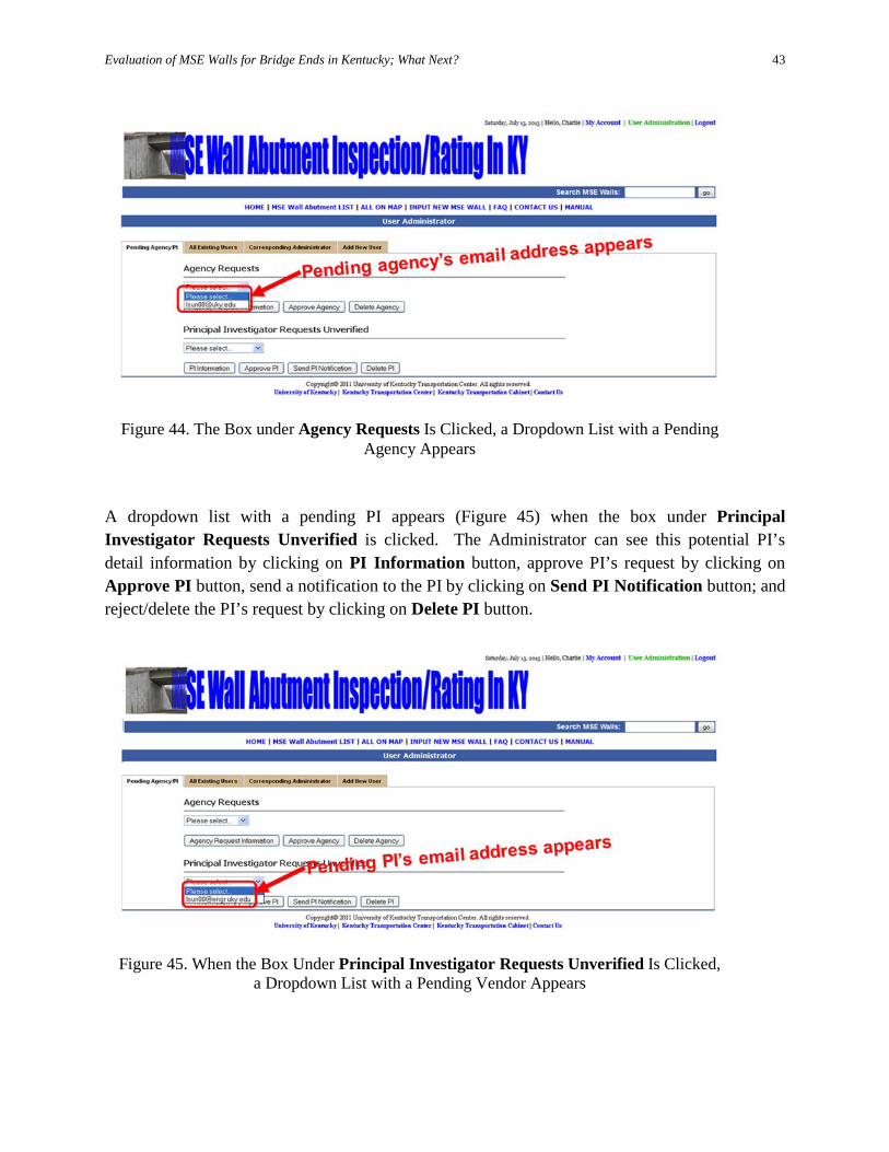
A dropdown list with a pending PI appears (Figure 45) when the box under Principal Investigator Requests Unverified is clicked. The Administrator can see this potential PI’s detail information by clicking on PI Information button, approve PI’s request by clicking on Approve PI button, send a notification to the PI by clicking on Send PI Notification button; and reject/delete the PI’s request by clicking on Delete PI button.
Figure 44. The Box under Agency Requests Is Clicked, a Dropdown List with a Pending
Agency Appears
Figure 45. When the Box Under Principal Investigator Requests Unverified Is Clicked,
a Dropdown List with a Pending Vendor Appears
Evaluation of MSE Walls for Bridge Ends in Kentucky; What Next?
44
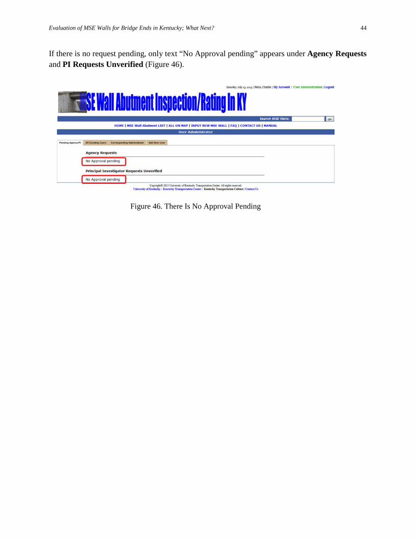
If there is no request pending, only text “No Approval pending” appears under Agency Requests and PI Requests Unverified (Figure 46).
Figure 46. There Is No Approval Pending
Evaluation of MSE Walls for Bridge Ends in Kentucky; What Next?
45
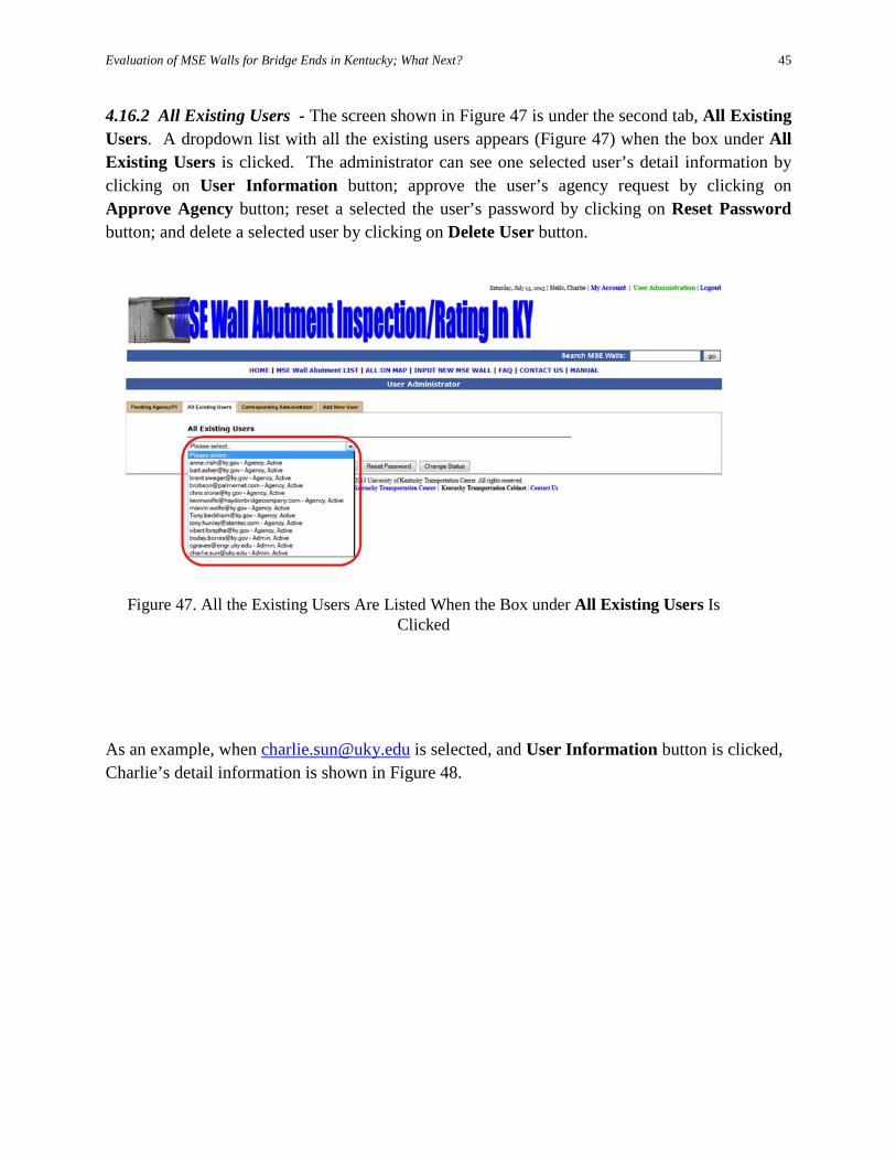
4.16.2 All Existing Users - The screen shown in Figure 47 is under the second tab, All Existing Users. A dropdown list with all the existing users appears (Figure 47) when the box under All Existing Users is clicked. The administrator can see one selected user’s detail information by clicking on User Information button; approve the user’s agency request by clicking on Approve Agency button; reset a selected the user’s password by clicking on Reset Password button; and delete a selected user by clicking on Delete User button.
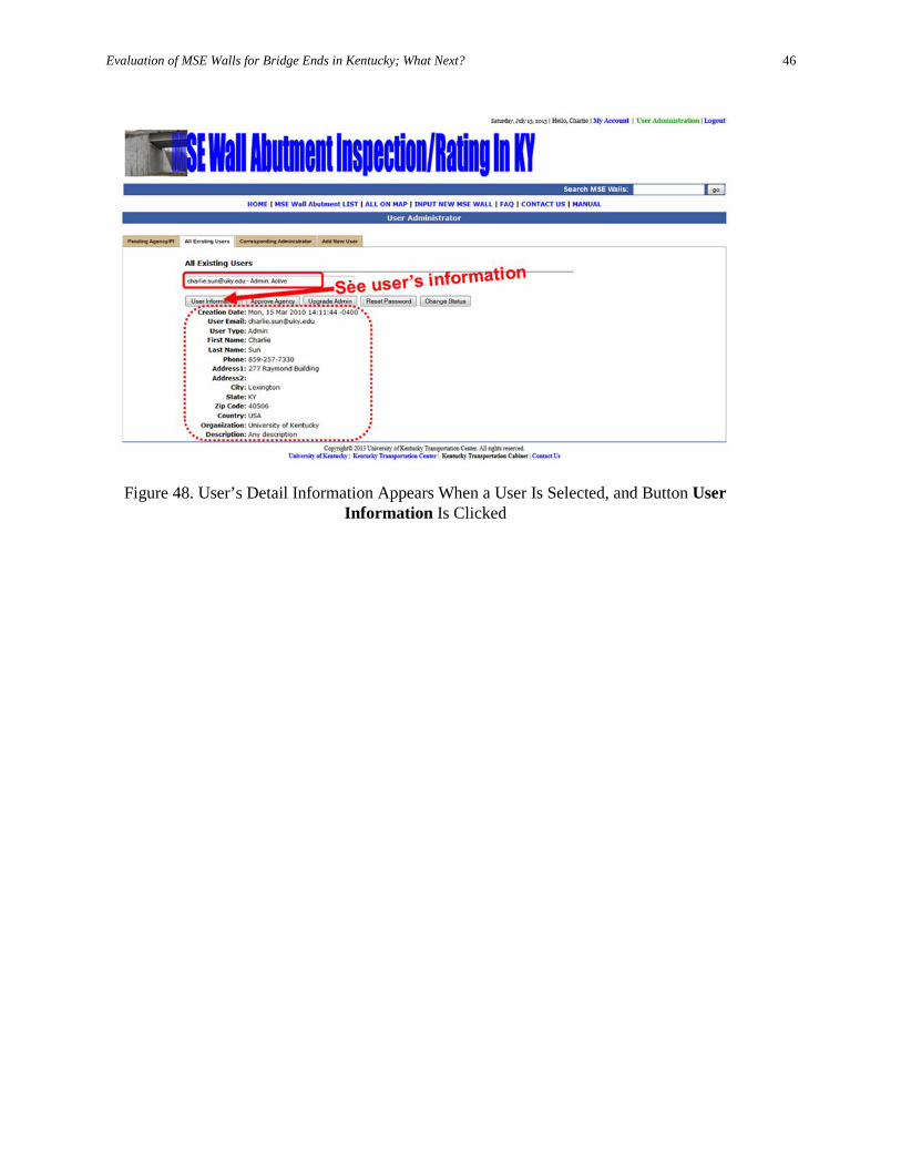
As an example, when [email protected] is selected, and User Information button is clicked, Charlie’s detail information is shown in Figure 48.
Figure 47. All the Existing Users Are Listed When the Box under All Existing Users Is
Clicked
Evaluation of MSE Walls for Bridge Ends in Kentucky; What Next?
46
Figure 48. User’s Detail Information Appears When a User Is Selected, and Button User
Information Is Clicked
Evaluation of MSE Walls for Bridge Ends in Kentucky; What Next?
47
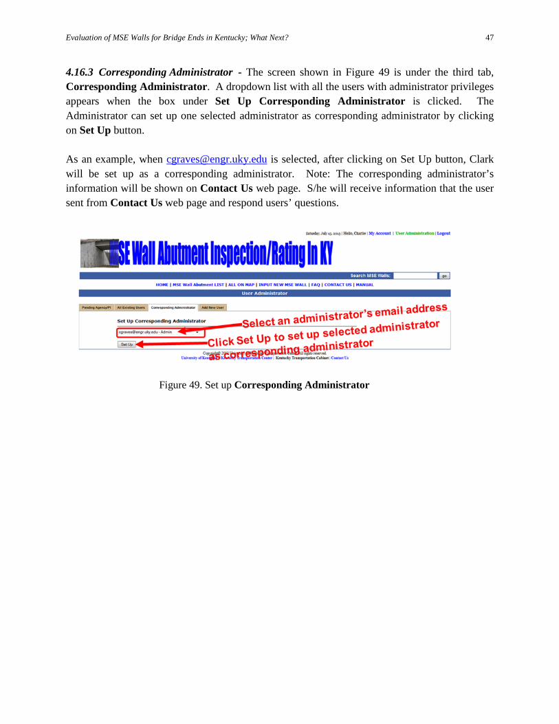
4.16.3 Corresponding Administrator - The screen shown in Figure 49 is under the third tab, Corresponding Administrator. A dropdown list with all the users with administrator privileges appears when the box under Set Up Corresponding Administrator is clicked. The Administrator can set up one selected administrator as corresponding administrator by clicking on Set Up button. As an example, when [email protected] is selected, after clicking on Set Up button, Clark will be set up as a corresponding administrator. Note: The corresponding administrator’s information will be shown on Contact Us web page. S/he will receive information that the user sent from Contact Us web page and respond users’ questions.
Figure 49. Set up Corresponding Administrator
Evaluation of MSE Walls for Bridge Ends in Kentucky; What Next?
48
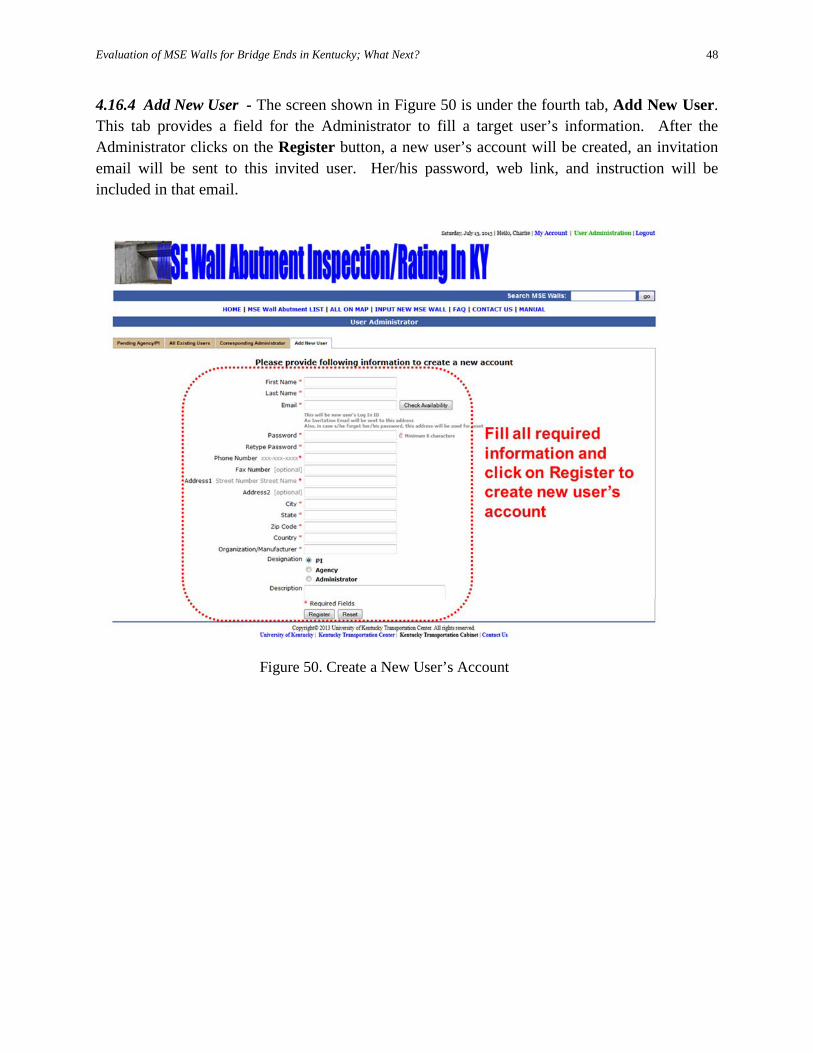
4.16.4 Add New User - The screen shown in Figure 50 is under the fourth tab, Add New User. This tab provides a field for the Administrator to fill a target user’s information. After the Administrator clicks on the Register button, a new user’s account will be created, an invitation email will be sent to this invited user. Her/his password, web link, and instruction will be included in that email.
Figure 50. Create a New User’s Account
Evaluation of MSE Walls for Bridge Ends in Kentucky; What Next?
49
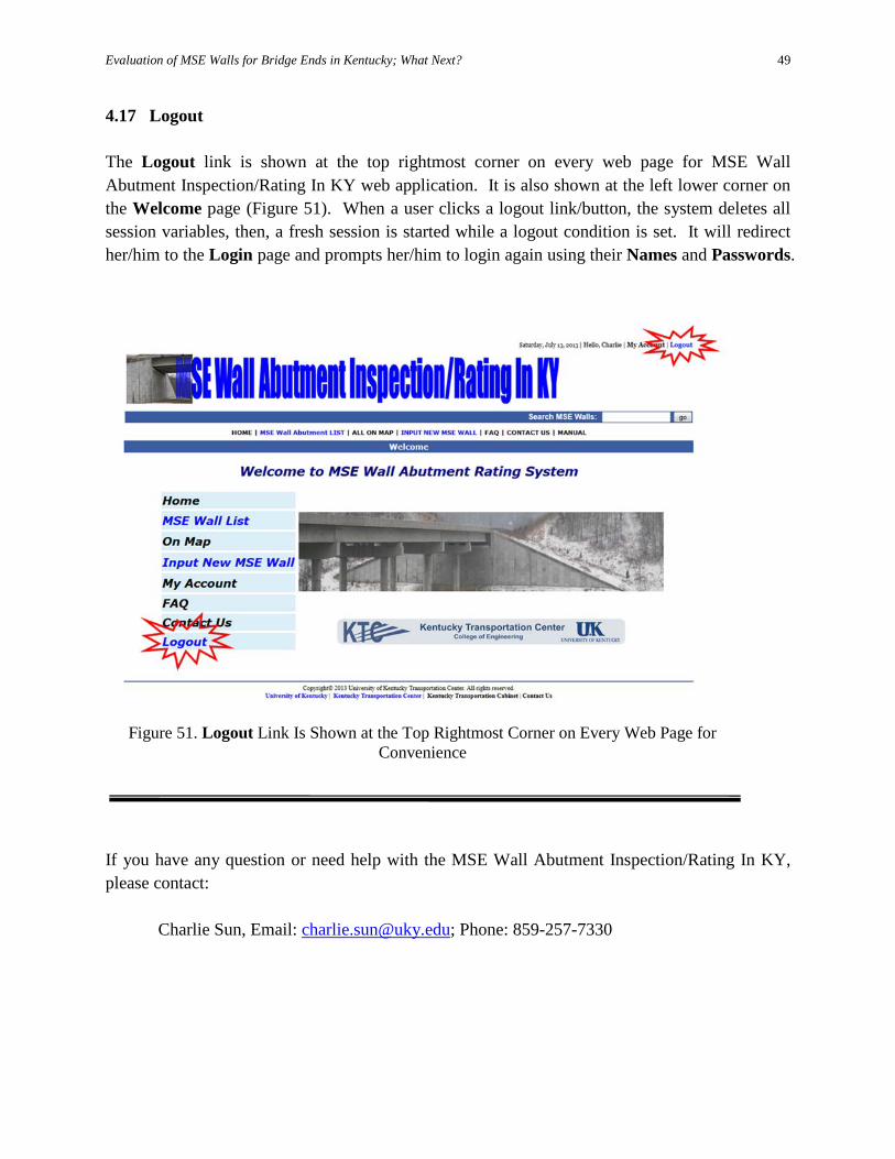
4.17 Logout The Logout link is shown at the top rightmost corner on every web page for MSE Wall Abutment Inspection/Rating In KY web application. It is also shown at the left lower corner on the Welcome page (Figure 51). When a user clicks a logout link/button, the system deletes all session variables, then, a fresh session is started while a logout condition is set. It will redirect her/him to the Login page and prompts her/him to login again using their Names and Passwords.
If you have any question or need help with the MSE Wall Abutment Inspection/Rating In KY, please contact:
Charlie Sun, Email: [email protected]; Phone: 859-257-7330
Figure 51. Logout Link Is Shown at the Top Rightmost Corner on Every Web Page for Convenience
Evaluation of MSE Walls for Bridge Ends in Kentucky; What Next?
50
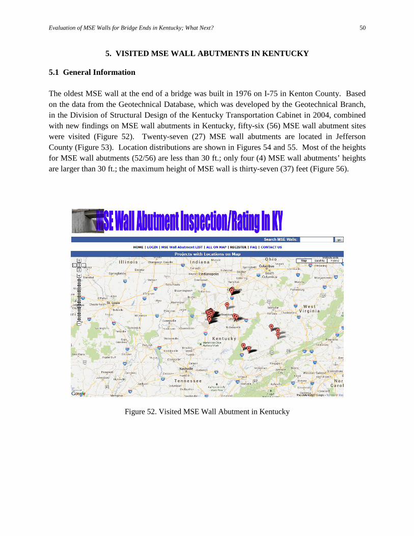
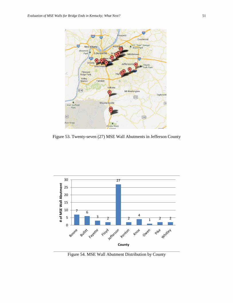
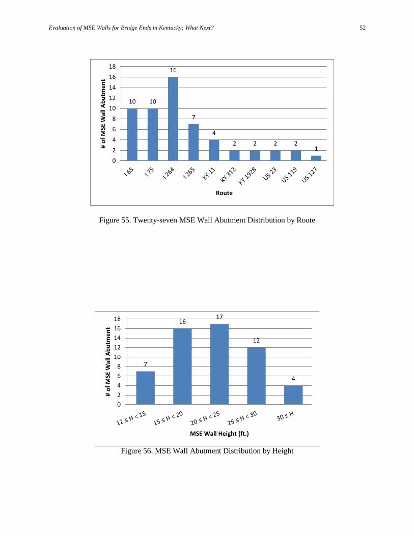
5. VISITED MSE WALL ABUTMENTS IN KENTUCKY 5.1 General Information The oldest MSE wall at the end of a bridge was built in 1976 on I-75 in Kenton County. Based on the data from the Geotechnical Database, which was developed by the Geotechnical Branch, in the Division of Structural Design of the Kentucky Transportation Cabinet in 2004, combined with new findings on MSE wall abutments in Kentucky, fifty-six (56) MSE wall abutment sites were visited (Figure 52). Twenty-seven (27) MSE wall abutments are located in Jefferson County (Figure 53). Location distributions are shown in Figures 54 and 55. Most of the heights for MSE wall abutments (52/56) are less than 30 ft.; only four (4) MSE wall abutments’ heights are larger than 30 ft.; the maximum height of MSE wall is thirty-seven (37) feet (Figure 56).
Figure 52. Visited MSE Wall Abutment in Kentucky
Evaluation of MSE Walls for Bridge Ends in Kentucky; What Next?
51
Figure 53. Twenty-seven (27) MSE Wall Abutments in Jefferson County
Figure 54. MSE Wall Abutment Distribution by County
7 6 3 2
27
2 4
1 2 2
0
5
10
15
20
25
30
# of
MSE
Wal
l Abu
tmen
t
County
Evaluation of MSE Walls for Bridge Ends in Kentucky; What Next?
52
Figure 55. Twenty-seven MSE Wall Abutment Distribution by Route
10 10
16
7
4 2 2 2 2
1
02468
1012141618
# of
MSE
Wal
l Abu
tmen
t
Route
Figure 56. MSE Wall Abutment Distribution by Height
7
16 17
12
4
02468
1012141618
# of
MSE
Wal
l Abu
tmen
t
MSE Wall Height (ft.)
Evaluation of MSE Walls for Bridge Ends in Kentucky; What Next?
53
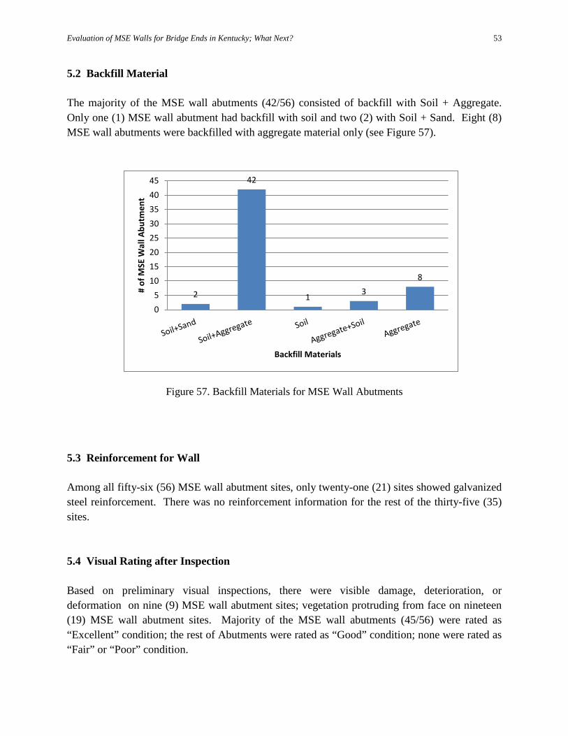
5.2 Backfill Material The majority of the MSE wall abutments (42/56) consisted of backfill with Soil + Aggregate. Only one (1) MSE wall abutment had backfill with soil and two (2) with Soil + Sand. Eight (8) MSE wall abutments were backfilled with aggregate material only (see Figure 57).
5.3 Reinforcement for Wall Among all fifty-six (56) MSE wall abutment sites, only twenty-one (21) sites showed galvanized steel reinforcement. There was no reinforcement information for the rest of the thirty-five (35) sites. 5.4 Visual Rating after Inspection Based on preliminary visual inspections, there were visible damage, deterioration, or deformation on nine (9) MSE wall abutment sites; vegetation protruding from face on nineteen (19) MSE wall abutment sites. Majority of the MSE wall abutments (45/56) were rated as “Excellent” condition; the rest of Abutments were rated as “Good” condition; none were rated as “Fair” or “Poor” condition.
Figure 57. Backfill Materials for MSE Wall Abutments
2
42
1 3 8
05
1015202530354045
# of
MSE
Wal
l Abu
tmen
t
Backfill Materials

Evaluation of MSE Walls for Bridge Ends in Kentucky; What Next?
54
All the inspection/rating results and pictures taken from the inspections were inputted in the MSE Wall Abutment Inspection/Rating In KY web Application. The data are available for both registered and non-registered users.
Evaluation of MSE Walls for Bridge Ends in Kentucky; What Next?
55
6. DESIGN GUIDANCE, CONSTRUCTION AND MAINTENANCE INSPECTOR’S HANDBOOK
6.1 Design Guidance
The design guidance was prepared to assist Kentucky design engineers, specification writers, and estimators with the selection and design of Mechanically Stabilized Earth (MSE) Wall Abutments. Its principal function is to serve as a reference source to the materials presented. It serves as a primary technical guideline on the use of these technologies on transportation facilities. The majority of the information in the design guidance was reproduced from Mechanically Stabilized Earth Walls and Reinforced Soil Slopes, Design and Construction Guidelines, Publication Number Vol. I - FHWA-NHI-10-024, and Vol. II - FHWA-NHI-10-025 2009, LRFD Bridge Design Specifications. 4th Edition, with 2008 and 2009 Interims published by American Association of State Highway and Transportation Officials, Washington, D.C. 2007, and Earth Retaining Structures, FHWA-NHI-07-071 by Tanyu, B.F., Sabatini, P.J. and Berg, R.R., U.S. Department of Transportation, Federal Highway Administration, Washington, D.C., 2008. The guidance is a separated document which will not be included in this report. 6.2 Construction and Maintenance Inspector’s Handbook
The construction and maintenance inspector’s handbook is primarily intended for use by inspectors who are charged with overseeing the construction of mechanically stabilized earth (MSE) walls. The material presented in this handbook is not intended to address design issues, but to highlight sound construction methods that will enable the MSE wall to function successfully. The handbook is also provided for post-construction inspection. The majority of information in the construction and maintenance inspector’s handbook was taken from Mechanically Stabilized Earth Walls and Reinforced Soil Slopes, Design and Construction Guidelines, Publication Number Vol. I - FHWA-NHI-10-024, and Vol. II - FHWA-NHI-10-025 2009, Mechanically Stabilized Earth Wall Inspector’s Handbook published by Florida Department of Transportation, Geotechnical Engineer Paul D. Passe, P.E., CPM, 2000, and was reproduced from Inspection Guidelines for Construction and Post-Construction of Mechanically Stabilized Earth Wall by David P. Vankavelarr, Delaware Department of Transportation, Dov Leshchinsky, Department of Civil and Environmental Engineering, College of Engineering, University of Delaware, November 2002. The handbook is distributed separately and is not shown in this report.
Evaluation of MSE Walls for Bridge Ends in Kentucky; What Next?
56
7. CONCLUSIONS AND RECOMMENDATIONS Due to the advantages of more rapid construction and lower cost of MSE wall abutments as compared to conventional concrete abutments, 80% of states/provinces (33/41), who participated in a nationwide MSE wall status survey, used MSE walls as abutments in their highway construction. The majority of states/provinces (30/33) used galvanized steel as reinforcement in the MSE wall as an abutment. An interesting survey result is that fourteen (14) states/provinces used geogrid and five (5) states/provinces used geotextile as reinforcement in the MSE wall abutment construction. A more interesting survey result is that one state is implementing GRS-IBS system. Most of the states/provinces (26/33) used aggregate as backfill materials for MSE wall abutment. Majority of states/provinces (27/33) limited the maximum height for the MSE wall abutment equal to or less than 40 feet; only one (1) state allowed the maximum height of 50 feet. All the states/provinces (33/33), who used MSE wall as an abutment, allowed MSE wall footing to be built on soil. Only seven (7) states/provinces allowed bridge beams/girders bearing on MSE wall itself directly. There were MSE wall abutment failures in 36% (12/33) states/provinces. Failure reaches 10 times in one (1) state. Seven (7) states/provinces had failure type "Settlement/washout of backfill material". Three (3) states/provinces had a formalized maintenance rating system for MSE wall abutments. Twenty-four (24), which is 73% out of 33, states/provinces had guidelines for building MSE wall abutments. Only two (2) states/provinces had maintenance inspector’s handbook for MSE wall abutments. To aid in the rating process for maintenance, a preliminary web application for the MSE Wall Abutment Inspection/Rating In KY has been developed. In efforts to assist the users of the MSE Wall Abutment Inspection/Rating In KY web application, many handy features in web application are highlighted, and various graphical user interfaces of the web application were illustrated and described. This web application is ready for inspectors to explore when they inspect and rate the MSE wall abutments in Kentucky. Fifty-six (56) MSE wall abutment sites in Kentucky were inspected and rated. Most of the heights for MSE wall abutments (52/56) were less than 30 ft.; only four (4) MSE wall abutments had heights larger than 30 ft.; the maximum height of MSE wall was 37 feet. Based on preliminary visual inspection, there were visible damage, deterioration, or deformation on nine (9) MSE wall abutment sites; vegetation protruding from face on nineteen (19) MSE wall abutment sites. Majority of MSE wall abutments (45/56) were rated as “Excellent” condition; rest of the abutments were rated as “Good” condition; none were rated as “Fair” or “Poor” condition. All the inspection/rating results and pictures taken from the inspections were inputted in the MSE Wall Abutment Inspection/Rating In KY web application. All data are available for both registered and non-registered users. More MSE wall abutments are expected to be inspected and rated, while MSE Wall Abutment Inspection/Rating In KY web application will be used to manage and share the data statewide.
Evaluation of MSE Walls for Bridge Ends in Kentucky; What Next?
57
The design guidance and construction & maintenance inspector’s handbook were developed mainly based on Mechanically Stabilized Earth Walls and Reinforced Soil Slopes, Design and Construction Guidelines, Publication Number Vol. I - FHWA-NHI-10-024, and Vol. II - FHWA-NHI-10-025 2009, LRFD Bridge Design Specifications. 4th Edition, with 2008 and 2009 Interims published by American Association of State Highway and Transportation Officials (AASHTO), Washington, D.C. 2007. It is expected to assist Kentucky design engineers, specification writers, and estimators with the selection and design of Mechanically Stabilized Earth (MSE) wall abutments by using the guidance and handbook compiled from this study.
Evaluation of MSE Walls for Bridge Ends in Kentucky; What Next?
58
REFERENCES AASHTO (2007). LRFD Bridge Design Specifications. 4th Edition, with 2008 and 2009
Interims, American Association of State Highway and Transportation Officials, Washington, D.C.
AASHTO (2006). Standard Specifications for Geotextiles - M 288, Standard Specifications for Transportation Materials and Methods of Sampling and Testing, 26th Edition, American Association of State Transportation and Highway Officials, Washington, D.C.
AASHTO (2004). LRFD Bridge Construction Specifications, 2nd Edition, 2004, with 2006, 2007, 2008, and 2009 Interim Revisions
AASHTO (2002). Standard Specifications for Highway Bridges, 17th Edition, American Association of State Highway and Transportation Officials, Washington, D.C.
AASHTO (1994). 1994 Interims to 1992 Standard Specifications for Highway Bridges, 15th Edition, American Association of State Highway and Transportation Officials, Washington, D.C.
Allen, T.M., Bathurst, R.J., Lee, W. F., Holtz, R.D. and Walters, D.L., (2004) “A New Method for Prediction of Loads in Steel Reinforced Walls”, ASCE Journal of Geotechnical and Geo-environmental Engineering, Vol. 130, No. 11, pp. 1109-1120.
Allen, T., Christopher, B.R., Elias, V.E. and DiMaggio, J. (2001) Development of the Simplified Method for Internal Stability Design of Mechanically Stabilized Earth (MSE) Walls, Washington State Department of Transportation Research Report WARD 513.1, 108 p.
Allen et al. 1993 Allen, T.M., Christopher, B.R. and Holtz, R.D., (1992), “Performance of a 12.6 m High Geotextile Wall in Seattle, Washington,” Geosynthetics Reinforced Soil Retaining Walls, J.T.H. Wu Editor, A.A. Balkema, Rotterdam, pp. 81-100.
Anderson, P.L., Brabant, K. (2005). "Increased Use of MSE Abutments," Proceedings of the 22nd Annual International Bridge Conference, Pittsburgh, PA, paper 5-10.
Bathurst, R. J., Miyata, Y., Nernheim, A., and Allen, T. M., (2008), “Refinement of Kstiffness Method for geosynthetic reinforced soil walls,” Geosynthetics International, Vol. 15, No. 4, pp. 269-295.
Bathurst, R.J., Walters, D., Vlachopoulos, N., Burgess P., and Allan, T.H., (2000). “Fullscale Testing of Geosynthetic Reinforced Walls,” Proceedings of GeoDenver, ASCE Special Publication 2000.
Berg, R.R., Christopher, B.R. and Samtani, N.C. (2009). Design and Construction of Mechanically Stabilized Earth Walls and Reinforced Soil Slopes, FHWA NHI-10-024 Volume I and NHI-10-025 Volume II, U.S. Department of Transportation, Federal Highway Administration, Washington, D.C., 306 p (Vol I) and 380p (Vol II).
Evaluation of MSE Walls for Bridge Ends in Kentucky; What Next?
59
Christopher, B. R., Gill, S. A., Giroud, J. P., Juran, I., Mitchell, J. K., Schlosser, F., and Dunnicliff, J., (1990). “Design and Construction Guidelines for Reinforced Soil Structure - Volume 1.” FHWA-RD-89-043, Federal Highway Administration, Washington, D. C.
Collin J.G. (1986). Earth Wall Design, Doctor of Philosophy Dissertation, University of Berkeley, 419 p.
Elias, V., Fishman, K.L., Christopher, B.R. and Berg, R.R. (2009). Corrosion/Degradation of Soil Reinforcements for Mechanically Stabilized Earth Walls and Reinforced Soil Slopes, U.S. Department of Transportation, Federal Highway Administration, Washington DC, FHWA-NHI-09-087, 146 p.
Elias, V., Welsh, J., Warren, J., Lukas, R.,. Collin, J.G. and Berg, R.R. (2006). Ground Improvement Methods, U.S. Department of Transportation, Federal Highway Administration, Washington, D.C., FHWA NHI-06-019 (Vol. I) and FHWA NHI-06-020 (Vol. II), 2006.
Elias, V, Christopher, B.R. and Berg, R.R. (2001). Mechanically Stabilized Earth Walls and Reinforced Soil Slopes, Design and Construction Guidelines, U.S. Department of Transportation, Federal Highway Administration, Washington DC, FHWA-NHI-00-043, 418 p.
Elias, V. and Christopher, B.R., (1997). Mechanically Stabilized Earth Walls and Reinforced Soil Slopes, Design and Construction Guidelines, Federal Highway Administration, FHWA SA-96-071, Washington, D.C., 371 p.
Meyerhof, G.G., (1951). “The Ultimate Bearing Capacity of Foundations.” Geotechnique Vol. 2 pp. 301-332.
Munfakh, G., Arman, A., Collin, J.G., Hung, J,C-J. and Brouillette, R.P. (2001). Shallow Foundations, Federal Highway Administration, FHWA-NHI-01-023, Washington, D.C., 222 p.
NCMA (2009). Design Manual for Segmental Retaining Walls, National Concrete Masonry Association, 3rd Edition, Herndon, VA.
Passe, Paul D. (2000). "Mechanically Stabilized Earth Wall Inspector’s Handbook." Florida Department of Transportation, Tallahassee, FL, September 14, 2000.
Prandtl, L. (1921). àber die eindingungsfestigkeit (hate) plasticher baustoffe und die festigkeit von schneiden, Zeitschrift fár Angewandte Mathematik und Mechanik, Vol 1, No. 1, pp. 15-20.
Samtani, N. C. and Nowatzki, E. A. (2006). “Soils and Foundations”, Reference Manual - Volume I and II, Report No. FHWA NHI-06-088 and FHWA NHI-06-089, Federal Highway Administration, U. S. Department of Transportation.
Evaluation of MSE Walls for Bridge Ends in Kentucky; What Next?
60
Schwanz, N., Meyers, M.S., and Berg, R.R. (1997). Specifying and Bidding Segmental Concrete Faced MSE Walls on Corps of Engineers Projects, Proceedings of Geosynthetics '97 Conference, Long Beach, California, pp. 789-801.
Simac, M.R., Bathhurst R.J. Berg R.R., Lothspeich S.E., (1993). Design Manual for Segmental Retaining Walls, National Concrete Masonry Association. Herndon, VA, 1993, 336 p.
Tanyu, B.F., Sabatini, P.J. and Berg, R.R. (2008). Earth Retaining Structures, U.S. Department of Transportation, Federal Highway Administration, Washington, D.C., FHWA-NHI-07-071, 2008.
Vankavelarr, David P. and Leshchinsky, Dov (2002). " Inspection Guidelines for Construction and Post-Construction of Mechanically Stabilized Earth Wall." Delaware Center for Transportation, University of Delaware, Newark, DE, November 2002.
Vesic, A.S. (1975). Bearing Capacity of Shallow Foundations, Foundation Engineering Handbook, Winterkorn, H. and H.Y. Fang, H.Y. (Eds.), Van Nostrand Reinhold Co., New York, NY, Chapter 3, pp. 121-147.
Wu, J.T.H, Lee, K., Helwany, S., and Ketchart, K. (2006). Design and Construction Guidelines for Geosynthetic-Reinforced Soil Bridge Abutments with a Flexible Facing System, NCHRP Report 556, Project 12-59, National Cooperative Highway Research Program, Transportation Research Board, National Research Council, Washington, D.C.


![GABION WALLS DESIGNgabions.net/downloads/Documents/MGS_Design_Guide.pdf · Mechanically Stabilized Earth (MSE) Gabion Wall [Reinforced Soil Wall] GABION WALLS DESIGN Gabion Gravity](https://img.pdfslide.us/doc/110x75/5a79b6847f8b9a9e0c8c102b/gabion-walls-stabilized-earth-mse-gabion-wall-reinforced-soil-wall-gabion-walls.jpg)