Embed Size (px)
Citation preview
Retrospective Theses and Dissertations Iowa State University Capstones, Theses andDissertations
1987
Evaluation of light-gauge metal diaphragm behaviorand the diaphragms interaction with post framesGary Arlen AndersonIowa State University
Follow this and additional works at: https://lib.dr.iastate.edu/rtd
Part of the Civil Engineering Commons
This Dissertation is brought to you for free and open access by the Iowa State University Capstones, Theses and Dissertations at Iowa State UniversityDigital Repository. It has been accepted for inclusion in Retrospective Theses and Dissertations by an authorized administrator of Iowa State UniversityDigital Repository. For more information, please contact [email protected].
Recommended CitationAnderson, Gary Arlen, "Evaluation of light-gauge metal diaphragm behavior and the diaphragms interaction with post frames " (1987).Retrospective Theses and Dissertations. 8507.https://lib.dr.iastate.edu/rtd/8507
INFORMATION TO USERS
While the most advanced technology has been used to photograph and reproduce this manuscript, the quality of the reproduction is heavily dependent upon the quality of the material submitted. For example:
• Manuscript pages may have indistinct print. In such cases, the best available copy has been filmed.
• Manuscripts may not always be complete. In such cases, a note will indicate that it is not possible to obtain missing pages.
• Copyrighted material may have been removed from the manuscript. In such cases, a note will indicate the deletion.
Oversize materials (e.g., maps, drawings, and charts) are photographed by sectioning the original, beginning at the upper left-hand comer and continuing from left to right in equal sections with small overlaps. Each oversize page is also filmed as one exposure and is available, for an additional charge, as a standard 35mm slide or as a 17"x 23" black and white photographic print.
Most photographs reproduce acceptably on positive microfilm or microfiche but lack the clarity on xerographic copies made from the microfilm. For an additional charge, 35mm slides of 6"x 9" black and white photographic prints are available for any photographs or illustrations that cannot be reproduced satisfactorily by xerography.
8716737
Anderson, Gary A rien
EVALUATION OF LIGHT-GUAGE METAL DIAPHRAGM BEHAVIOR AND THE DIAPHRAGMS INTERACTION WITH POST FRAMES
Iowa State University PH.D. 1987
University Microfilms
I ntBrnStiOnS! 300 N. Zeeb Road, Ann Arbor, Ml 48106

PLEASE NOTE:
In all cases this material has been filmed in the best possible way from the available copy. Problems encountered with this document have been identified here with a check mark V .
1. Glossy photographs or pages ^
2. Colored illustrations, paper or print
3. Photographs with dark background ./
4. Illustrations are poor copy
5. Pages with black marks, not original copy
6. Print shows through as there is text on both sides of page
7. Indistinct, broken or small print on several pages J 8. Print exceeds margin requirements
9. Tightly bound copy with print lost in spine
10. Computer printout pages with indistinct print
11. Page(s) lacking when material received, and not available from school or author.
12. Page(s) seem to be missing in numbering only as text follows.
13. Two pages numbered . Text follows.
14. Curling and wrinkled pages
15. Dissertation contains pages with print at a slant, filmed as received
16. Other
University Microfilms
international
Evaluation of light-gauge metal diaphragm behavior and the
diaphragms interaction with post frames
'Gary Arlen Anderson
A Dissertation Submitted to the
Graduate Faculty in Partial Fulfillment of the
Requirements for the Degree of
DOCTOR OF PHILOSOPHY
Major: Agricultural Engineering
Approved:
In Charge of Major Work
For the Major ^artment
For ^heC/Grâduate College
Iowa State University Ames, Iowa
1987
Signature was redacted for privacy.
Signature was redacted for privacy.
Signature was redacted for privacy.
il
TABLE OF CONTENTS
Page
INTRODUCTION 1
Objectives 5
REVIEW OF LITERATURE 7
Verification of the Existence of Diaphragm Action 7
Models of Diaphragm-Frame Interactions 9
Diaphragm Stiffness 14
Testing 14
Analytical Methods 15
Buckling of Sheeting 24
Diaphragms Made of Metal Sheeting on Wood Frames 25
Stiffness Variation of Diaphragms Made of Metal Sheeting on Wood Frames 28
Recommended Design Practices 28
Applications by Others 30
TEST PROCEDURE AND APPARATUS 35
Test Equipment - General 36
Test Equipment - Special 42
Diaphragm Framing 50
Diaphragm Sheeting 57
Fasteners 51
Diaphragms Tested 61
Strongpanel Tests 66
Grandrib 3 Tests 68
i i i
Loading 79
Calibration 80
Purlin Modulus of Elasticity 81
RESULTS AND DISCUSSION 85
Modulus of Elasticity of Edge Purlins 86
Diaphragm Computer Analysis 89
Strongpanel 96
Control diaphragms 1 and 15 96 Diaphragms with 33% of steel removed: 2,3,12,14 101 Diaphragms with 11% of steel missing: 4, 5, 6, 9,
10, and 13 105 Diaphragms with purlin recessed: 7, 8, and 11 111
Grandrib 3 114
Control diaphragms la, 4a, and 14a 114 Diaphragms with seams at 6 ft.: 2a, 5a, and 8a 120 Diaphragms with seams at 4 ft.: 3a, 6a, and 7a 121 Diaphragms with alternate fastener pattern: 9a,
10a, and lia 123 Diaphragms with purlins flat: 11a and 12a 125 Diaphragms that were repeat loaded: 15a and 16a 127 Purlin axial strain: Diaphragms 14a, 15a and 16a 131 Strain gauge rosettes: Diaphragms 15a and 16a 136 Brittle coat test: Diaphragm 152 145
General Comments 147
PROPOSED PREDICTIVE MODELS 153
Diaphragm-Frame Interaction 153
Diaphragm Stiffness 163
Analytical Model 167
Shear strain of sheeting 167 Profile distortion of sheeting 169 Sheet-purlin movement at sheet ends perpendicular
to corrugation 170 Rafter-purlin connector slip perpendicular to
corrugations 174 Bending deflection 174
iv
Movement due to rafter distortion 175 Sheet-purlin slip parallel to the corrugation 175 Purlin-rafter slip parallel to the corrugations 188 Shear connector-sheet slip 188 Shear connector-rafter slip 190 Purlin shear strain and bending strain 191 Twisting of purlins 191 Other considerations 193 Empirical equation 195
SUMMARY 197
RECOMMENDATIONS FOR CONTINUED RESEARCH 202
BIBLIOGRAPHY 204
ACKNOWLEDGMENTS 213
APPENDIX A: EFFECT OF TWO DIAPHRAGMS ACTING TOGETHER 214
APPENDIX B: ELIMINATION OF BENDING AND BRIDGE CONSTANT FOR PURLIN STRAIN GAUGE BRIDGE 218
APPENDIX C: DYNOMETER CALIBRATION 222
APPENDIX D: SCREW FASTENER STIFFNESS 225
APPENDIX E: RELATIONSHIP BETWEEN THE DIAPHRAGM SHEAR STIFFNESS WHEN LOADED PARALLEL AND PERPENDICULAR TO THE CORRUGATIONS 227
APPENDIX F: BENDING AND SHEAR DISPLACEMENT OF PURLINS 229
APPENDIX G: DISPLACEMENT DUE TO PURLIN TWIST 231
1
INTRODUCTION
Post-frame buildings are widely used throughout the Midwest in
agriculture. The buildings are generally used for the storage of
machinery and crops, and the housing of livestock. In recent years,
the agricultural economy has been depressed, causing post frame builders
to compete with light steel frame builders for the light commercial
building market. The post frame builders are attempting to make their
post frames more economical so that they can be more competitive with
the light steel frame builders and be economical enough for the
depressed agricultural economy. This study looks at the interaction of
the metal clad roof and the wood frame.
Typically, post framed buildings used in agriculture are gable
framed with clear span truss rafters of the Howe, Fink, or W type
spanning between 6 x 6 or 6 x 8 in. timber posts/columns which are
embedded in the ground. Light metal cladding is fastened by screws
or nails to dimension lumber wall girts or roof purlins. The clear
span of the trusses is 40 to 60 ft. with eave heights of 12 to 16 ft.
The truss and post spacing ranges from 6 to 12 ft. Often, large doors
are in the end walls and/or side walls.
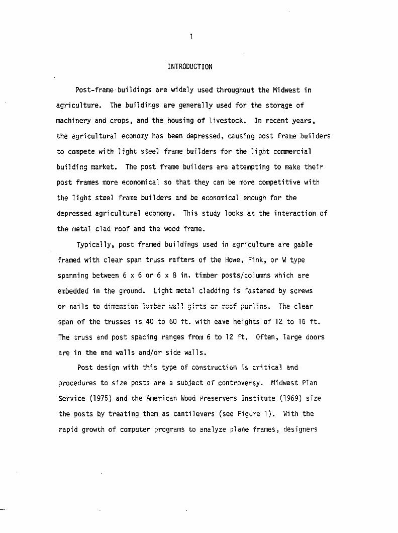
Post design with this type of construction is critical and
procedures to size posts are a subject of controversy. Midwest Plan
Service (1975) and the American Wood Preservers Institute (1969) size
the posts by treating them as cantilevers (see Figure 1). With the
rapid growth of computer programs to analyze plane frames, designers
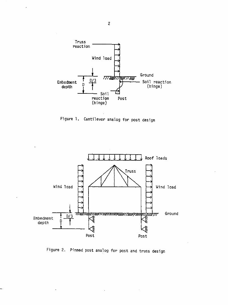
2
Truss reaction
Wind load
Embedment depth
n/q u/^//'W7U.
f . r — Soil reaction (hinge)
il—Z3
Ground
- Soil reaction (hinge)
Post
Figure 1. Cantilever analog for post desi gn
\i Jf X \"\i wJf », 1F Roof loads
Wind load
Embedment depth
Truss
Wind load
fn jrmir U rTT pi
Post Post
Ground
Figure 2. Pinned post analog for post and truss design
3
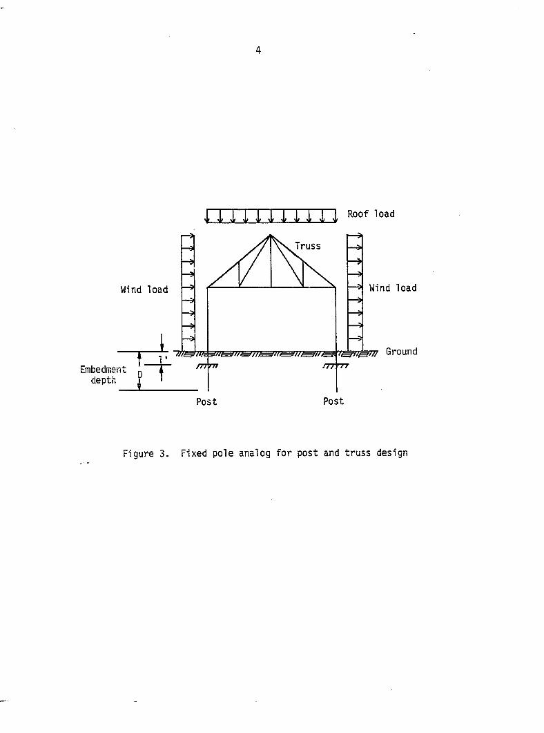
have begun to size posts with the truss (see Figures 2 and 3). Neither
of these procedures utilizes the ability of the roof cladding and
framing to transfer some of the lateral forces to shear walls, which
would decrease the lateral force that the frame would have to carry.
Ignoring the portion of the force transferred to the shear walls
by the roof framing and sheeting is not necessarily conservative. Shear
force on the cladding fasteners will be present even if the force
carried by the cladding is ignored in frame design (Stark and Toma,
1979). In long buildings, the force brought to the shear wall by
the roof may be larger than the force the end wall/shear wall is
designed to carry.
The in-plane stiffness and strength of roof and wall systems is
usually called diaphragm or stressed skin stiffness and strength, and
the transfer of lateral force by the roof framing and cladding to a
shear wall is called diaphragm or stressed skin action. Diaphragm
action may reduce post sizes and it will help in the sizing and
placement of lateral bracing.
A theoretical and empirical procedure was developed to determine
the diaphragm stiffness and strength. Thirty-one diaphragms were
constructed of typical post frame construction and tested to failure.
The tests were used to evaluate the theoretical procedure and to
assess the effect of several variables on the diaphragm's stiffness.
Analogs are also presented for analyzing post frame buildings taking
building diaphragm action into consideration.
4
Roof load
Wind load Wind load
Embedment depth
Truss
Tm.wn Tn TT rr TT in TmnMm Ground
Post Post
Figure 3. Fixed pole analog for post and truss design
5
The components of diaphragm framing and cladding stiffness which
contribute to the total diaphragm stiffness vary from investigator to
investigator. Theoretical and experimental studies include cladding
distortion and strain, movement between cladding and purlins, and
movement between adjacent cladding sheets. Some theoretical studies
have looked at cladding to shear connector stiffness. Experimental
studies often seem to exclude all of the movements between rafter and
shear connectors, rafter and purlin, and cladding and shear connectors.
The stiffness components which comprise the total diaphragm stiffness
are dependent on framing and a brief discussion is presented.
Objectives
The objectives of this study were to:
1. Evaluate the effect of openings in the sheeting in relation
to their location and size on diaphragm stiffness.
2. Determine if the steel extending beyond the edge purlin is
effective as part of the diaphragm for lengths that are common in
post frame structures.
3. Assess the effect of multiple sheet lengths in the length of
the diaphragm on the diaphragm's stiffness.
4. Determine the effect of a reduced fastener pattern on the
diaphragm's stiffness.
5. Evaluate the effect on the diaphragm's stiffness of the
purlins being placed flat.
6
6. Evaluate the strains in the edge purlins and the sheeting.
7. Assess the different definitions of diaphragm stiffness.
8. Develop an analytical method to predict diaphragm stiffness for
diaphragms commonly used in post frame structures.
9. Evaluate methods of applying diaphragm action to building
systems.
7
REVIEW OF LITERATURE
Several different types of structural diaphragms have been
investigated over the last 30 years. The research has included roof
and ceiling diaphragms, wall diaphragms (Tuomi and McCutcheon, 1978;
Thomas, 1980), and diaphragms which are continuous over supports
(Tarpy et , 1985). Diaphragms are normally classified according to
the type of material the sheeting or skin is made of and the type of
material the frame is made of. For example, diaphragms can be made of
steel sheeting on a steel frame (see Figure 4) or wood sheeting on a wood
frame. Investigation of the properties of steel sheeting on steel
frame diaphragms and wood sheeting on wood frame diaphragms was '
underway in the early to mid 1950s (Nilson, 1956; Countryman, 1952).
Research on composite types of diaphragms, such as concrete on a steel
deck and insulation sandwiched between steel sheet diaphragms, began
in the late 1970s to early 1980s (Arnold et , 1978; La Boube and
Fisher, 1982). Diaphragms composed of metal sheeting on wood frames
were investigated by Hurst and Mason (1961). However, diaphragms of
metal sheeting on wood frames were not tested and analyzed as possible
structural components until the mid 1970s (Hausmann and Esmay, 1975).
Verification of the Existence of Diaphragm Action
The effect of roof diaphragms in light structures is to stiffen
the intermediate frames against horizontal movement by carrying a
portion of the horizontal force that is on the structural frame to
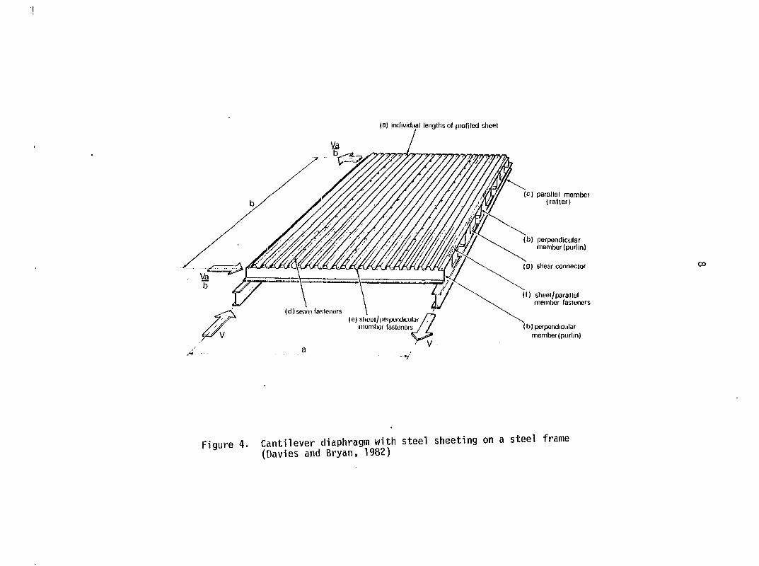
(a) Individual lengths of profiled sheet
( c ) p a r a l l e l m e m b e r (raher)
(b) perpendicular member (purlin)
(g) shear connector
I f ) s h e e t / p a r a l l e l member fasteners
(d)seani fasteners (e) sht!iîl/per|*i()dicular /
member fasteners / i ( b ) p e r p e n d i c u l a r
member (purlin)
"V
Figure 4. Cantilever diaphragm with steel sheeting on a steel frame (Davies and Bryan, 1982)
9
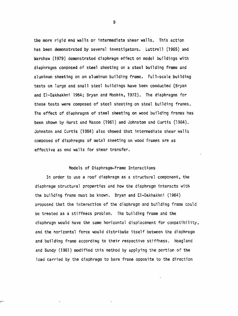
the more rigid end walls or intermediate shear walls. This action
has been demonstrated by several investigators. Luttrell (1965) and
Warshaw (1979) demonstrated diaphragm effect on model buildings with
diaphragms composed of steel sheeting on a steel building frame and
aluminum sheeting on an aluminum building frame. Full-scale building
tests on large and small steel buildings have been conducted (Bryan
and El-Dakhakhni 1964; Bryan and Moshin, 1972). The diaphragms for
these tests were composed of steel sheeting on steel building frames.
The effect of diaphragms of steel sheeting on wood building frames has
been shown by Hurst and Mason (1961) and Johnston and Curtis (1984).
Johnston and Curtis (1984) also showed that intermediate shear walls
composed of diaphragms of metal sheeting on wood frames are as
effective as end walls for shear transfer.
Models of Diaphragm-Frame Interactions
In order to use a roof diaphragm as a structural component, the
diaphragm structural properties and how the diaphragm interacts with
the building frame must be known. Bryan and El-Dakhakhni (1964)
proposed that the interaction of the diaphragm and building frame could
be treated as a stiffness problem. The building frame and the
diaphragm would have the same horizontal displacement for compatibility,
and the horizontal force would distribute itself between the diaphragm
and building frame according to their respective stiffness. Hoagland
and Bundy (1981) modified this method by applying the portion of the
load carried by the diaphragm to bare frame opposite to the direction
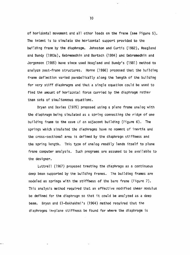
10
of horizontal movement and all other loads on the frame (see Figure 5).
The intent is to simulate the horizontal support provided to the
building frame by the diaphragm. Johnston and Curtis (1982), Hoagland
and Bundy (1983a), Gebremedhin and Bartsch (1984) and Gebremedhin and
Jorgensen (1985) have since used Hoagland and Bundy's (1981) method to
analyze post-frame structures. Home (1966) proposed that the building
frame deflection varied parabolically along the length of the building
for very stiff diaphragms and that a single equation could be used to
find the amount of horizontal force carried by the diaphragm rather
than sets of simultaneous equations.
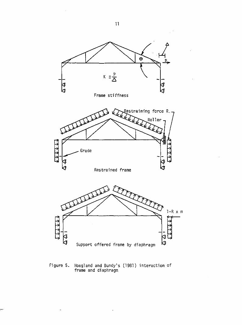
Bryan and Davies (1975) proposed using a plane frame analog with
the diaphragm being simulated as a spring connecting the ridge of one
building frame to the eave of an adjacent building (Figure 6). The
springs which simulated the diaphragms have no moment of inertia and
the cross-sectional area is defined by the diaphragm stiffness and
the spring length. This type of analog readily lends itself to plane
frame computer analysis. Such programs are assumed to be available to
the designer.
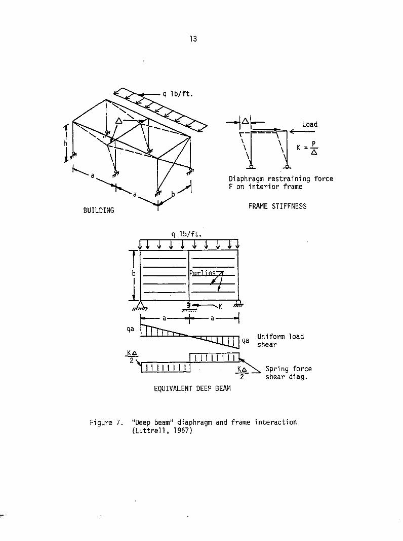
Luttrell (1967) proposed treating the diaphragm as a continuous
deep beam supported by the building frames. The building frames are
modeled as springs with the stiffness of the bare frame (Figure 7).
This analysis method required that an effective modified shear modulus
be defined for the diaphragm so that it could be analyzed as a deep
beam. Bryan and El-Dakhakhni's (1964) method required that the
diaphragms in-plane stiffness be found for where the diaphragm is
11
y \
b V
Frame stiffness
ining force R..
Grade
Restrained frame
1-R X m
Support offered frame by diaphragm
Figure 5. Hoagland and Bundy's (1981) interaction of frame and diaphragm
12
itn rm
Spread and sway
rm
Figure 6. Frame diaphragm interaction (Bryan and Davies, 1975)
13
BUILDING
H' Load
r ' \
K =
Diaphragm restraining force F on interior frame
FRAME STIFFNESS
q lb/ft.
Uniform load shear
Spring force shear diag.
EQUIVALENT DEEP BEAM
Figure 7. "Deep beam" diaphragm and frame interaction (Luttrell, 1967)
14
assumed to be attached to the building frame. Luttrel1's (1967)
method is not easily applied to frames which can be subjected to spread,
as well as sideway. The method does use a beam analogy which can be
analyzed by several structural analysis principles such as unit load
method or by direct integration (Yu, 1986; Hidgon et , 1967).
Diaphragm Stiffness
As previously mentioned, the structural properties of the
diaphragm need to be defined. The diaphragm's structural properties
can be found by testing or analytically from diaphragm geometry and
diaphragm component properties. The analytical methods can be based
on the energy method, equilibrium and compatibility, or the finite
element method.
Testing
Luttrel1 (1965) analytically derived an equation for the modified
shear modulus. The equation was dependent upon testing to define a
constant that describes the profile distortion for a given corrugation
cross-section and fastener pattern. The derivation is valid for a
diaphragm composed of one sheet which is not fastened to intermediate
purlins. Also, it is implicitly assumed that rafter/purlin
connections are not part of the diaphragm. Once the constant is known
for a given cross-section and end fastener pattern, the modified shear
modulus can be found for other diaphragm lengths. White (1978) and
Warshaw (1979) showed that Luttrel1's equation was valid for
15
diaphragms made of aluminum sheeting on wood frames provided the
length varied by no more than six feet from test conditions.
White (1978) had a misprint in his paper and it appeared that he
verified that LuttrelTs equation for the modified shear modulus was
valid for the diaphragm's shear stiffness. Hoagland (1981) used
LuttrelTs equation to adjust the diaphragm's shear stiffness from test
conditions in his design procedure. Johnston (1980) concluded from
Hoagland's procedure that for pitched roof buildings, the roof halves
should be treated as a single diaphragm with twice the length. It can
be shown that treating the roof as two independent diaphragms and
following the procedure of the American Iron and Steel Institute (1967)
will support Johnston's data (see Appendix A). The error in Hoagland's
(1981) design procedure has since been repeated in Hoagland and Bundy
(1983a), Gebremedhin and Bartsch (1984), and Gebremedhin and
Jorgensen (1985).
Analytical Methods
Nil son (1955) treated the diaphragm as a deep beam with three
components contributing to the deflection of the diaphragm. The
components of deflection are shear deflection of the sheeting, slip
of the seams, and axial extension of edge purlins. The shear
deflection of the sheeting was treated as if the sheeting was a
rectangular beam. The shape factor derived from his test data was
1.3, rather than 1,2 which can be derived from geometry (Gere and
Timoshenko, 1984), or 1*18 which can be derived from the principles of
16
elasticity (Cowper, 1966). Nil son tested panels that did not make use '
of intermediate purlins and he concluded that the profile distortion
vjould be negligible.
Bryan and Jackson (1967) presented analytical expressions for the
shear displacement of diaphragms which were derived from the energy
method. The terms included are the sheet profile distortion, shear
strain of the sheeting, and slip of the end fasteners. Test results of
full-scale diaphragms were presented and compared to predicted values
and it was concluded that the effect of sheet to purlin fasteners and
rafter to purlin connections could not be ignored. El-Dakhakhni (1967)
suggested that Bryan and Jackson's (1967) development of end fastener
slip on the assumption that a tension field developed in the sheeting
was in error. El-Dakhakhni stated that this was unlikely unless the
corrugation was flattened out. He proposed a new equation for end
fastener slip based on the sides being in pure shear. Bryan and
El-Dakhakhni (1968a) analytically developed equations for the
flexibility of the following components of a diaphragm using the energy
method:
1. Bending of sheet corrugation.
2. Shear strain of sheet.
3o Sheet to purlin fastener slip.
4. Sheet to rafter fastener slip.
5. Seam fastener slip.
6. Purlin to rafter connection slip.
7. Axial strain in purlins.
17
Adjustment factors were also developed to account for the effect of
intermediate purlins. Bryan and El-Dakhakhni (1968b) tested diaphragms
and compared the results with calculated behavior.
The profile distortion presented by Bryan and El-Dakhakhni (1968b)
assumes that the edges of the sheet remain straight, membrane and
torsion distortion is negligible when compared to bending, and the
purlins do not support the corrugation profile against out-of-plane
displacement. Falkenberg (1969) incorporated the support offered to
the sheeting from the purlins and noted that it reduces the
displacement due to bending of the corrugation by one-half. The
assumptions that the edges of the sheet remain straight and that bending
is the dominant term of profile distortion were changed by Home and
RasIan (1971a). Again, the energy method was employed, but the
deflected shape of the corrugation was assumed to be a sine wave and
the terms for bending, membrane stresses, and plate bending were
included. The results were shown to be in good agreement with a finite
difference solution (Home and Ras Ian, 1971b). Davies and Lawson (1975)
proposed to expand upon Home and Raslan's (1971a) work by assuming
that the corrugation distorted according to a Fourier series. Finite
element analysis was used to show that the Fourier series produced
more accurate results.
Bryan (1975) incorporated the effect of continuous purlins into
the diaphragm flexibility. Davies (1976a) proposed a new equation for
seam flexibility and purlin to rafter connection flexibility based on
sheet equilibrium. Davies also presented an effective shear modulus
18
for the sheeting for use in finite element modeling. He also tested a
parabolic and linear force distribution for sheet end fastener forces
perpendicular to the corrugation. Davies (1976b) gives guidelines as
to when the sheet end fastener forces should be treated linearly or
parabolically. El-Dakhakhni (1976) developed a model for use of
diaphragms which are used as wall partitions in tall buildings. In
1976, Bryan (1976) gave guidelines for diaphragm use. Bryan proposed
that the sheeting be intended for cladding primarily and that the shear
stress in the sheeting due to diaphragm action should not exceed
25% of the stress in the sheeting due to bending.
Easley (1977) developed equations for the diaphragm stiffness and
strength based on observed tear patterns in sheets and static
equilibrium of the forces and moments on the sheets similar to Davies
(1976a). Chockalingham et (1978) followed a method similar to
Easley, but concentrated on force and kept the derivations more
general. Ha et (1979) extended the work of Chockalingham et al.
for any fastener case. Neither Ha et aj[. or Chockalingham et al.
evaluated any forces or movements not associated with the sheeting.
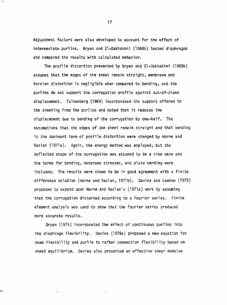
Davies and Lawson (1978) again expanded on the energy method used
to find the flexibility of the profile distortion. They assumed that
the corrugation displaced according to a Fourier series with 17 terms.
They also included six terms for in-plane shear of the corrugation
plates. The Fourier series does not follow the observed deflected
shape of the corrugation (Figure 8). Davies (1985a) proposed using a
power function to describe the displacement. Application of the
19
' I thickness
_J
< '
Figure 8. Deflected shape of corrugation
20
method is given by Davies (1986b).
In 1978, Davies (1978) proposed new types of light-weight steel
structures utilizing diaphragm action. He concluded that large savings
of material were possible when diaphragm action was used creatively.
Davies and Bryan (1979) tried to encourage diaphragm action use in
design by simplifying the design procedure. They developed design
tables for the interaction of the diaphragm and the building frame.
The design tables yield the diaphragm's allowable load and flexibility
for a given span to depth ratio, corrugation, and fastener pattern.
During the time that Bryan, Davies, Easley, and Ha were using the
energy methods and equilibrium and compatibility to determine
diaphragm stiffness and strength, Luttrell was developing the modified
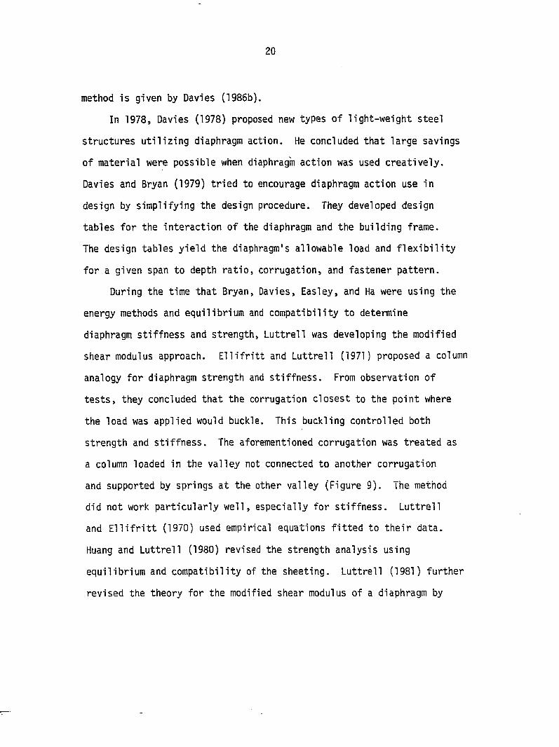
shear modulus approach. Ellifritt and Luttrell (1971) proposed a column
analogy for diaphragm strength and stiffness. From observation of
tests, they concluded that the corrugation closest to the point where
the load was applied would buckle. This buckling controlled both
strength and stiffness. The aforementioned corrugation was treated as
a column loaded in the valley not connected to another corrugation
and supported by springs at the other valley (Figure 9). The method
did not work particularly well, especially for stiffness. Luttrell
and Ellifritt (1970) used empirical equations fitted to their data.
Huang and Luttrell (1980) revised the strength analysis using
equilibrium and compatibility of the sheeting. Luttrell (1981) further
revised the theory for the modified shear modulus of a diaphragm by
21
LOAD
MODEL COLUMN
Figure 9. Column analogy of sheet corrugation (Ellifritt and Luttrell, 1971)
22
providing terms for pure shear displacement, warping displacement, slip
at interior side laps, slip at edge member, slip at end member, and
miscellaneous effects.
Luttrell's components which make up the modified shear modulus of
a diaphragm are similar to work done by others, except for the warping
displacement and the miscellaneous effects. The warping displacement
is found by applying a load to the top of the corrugation equal to,
but opposite to the membrane stresses and supporting the top flange
with an elastic foundation (Figure 10). The miscellaneous effects seem
to be a catch-all for axial extension of edge members and displacement
variation between test and theoretical values.
Computer models utilizing finite element techniques have been
used successfully to predict diaphragm strength and stiffness.
Generally, the finite element programs are considered to be too bulky
to use in design and they require that operators be able to generate
the material property matrix. Most design oriented finite element
programs generate the material properties matrix from basic mechanics
of materials for the user. Nilson and Ammar (1974) performed one of
the earlier finite element analyses. The material properties were
primarily found by testing elements. Their results for different
fastener forces provided the basis for the force distributions in
several of the previously described theoretical methods. In 1976,
Davies used finite element analysis to compare his theoretical work
(Davies, 1976a; 1976b). Ha (1979) used finite element analysis to
compare the energy method he presented to describe fastener behavior.
23
P'
Figure 10. Corrugation supported by elastic foundation (Luttrell, 1981)
24
Davies (1977) also used finite element analysis to compare to the
simplified plane truss analogy that he presented for finding diaphragm
properties. Atrek and Nil son (1980) further extended the work of
Nilson and Ammar (1974) to include nonlinear analysis which will
usually occur before failure. Their analyses indicated that the
fasteners were the major components of nonlinear behavior of the
diaphragms analyzed.
Buckling of Sheeting
Buckling of the sheeting is another possible source of nonlinear
behavior of the diaphragm and a possible failure mode. Nilson (1960a)
demonstrated that diaphragms of flat plates will buckle as thin plates.
This behavior is possible in the flat areas of corrugated diaphragms.
Easley and McFarland (1969) and Easley (1975) demonstrated that
diaphragms of corrugated sheeting could buckle in a sine wave fashion
across corrugations and developed equations to describe the buckling
using the sine wave deformation and the energy method. The equation
did not take into account that the sheeting is fastened at intermediate
purlins. Davies and Bryan (1982) state that the diaphragm can be
treated as being made up of individual plates spanning between purlins.
Rothwell (1967) and Sherman and Fisher (1971) found that in deep
beams, the webs did not have to be continuously fastened to prevent
buckling from being the failure mode.
25
Diaphragms Made of Metal Sheeting on Wood Frames
Almost all work done to date concerning diaphragms constructed of
metal sheeting on wood frames has been by testing. Turnbull and Guertin
(1975) tested single corrugated metal sheet on a wood frame and plywood
sheet on a wood frame. They attempted to correlate the diagonal
strain to the diagonal deformation of the diaphragm. Hausmann and
Esmay (1977) tested a simple beam arrangement which had 2x6 rafters
4 feet on-center and 2x4 purlins 2 feet on-center placed flat. The
sheeting was corrugated steel, 29 gauge, 30 x 96 in., and aluminum,
0.021 in. thick, 48 x 96 in. They concluded that fasteners and framing
were very important to diaphragm strength and stiffness. Warshaw (1979)
and White (1978) reported on the same tests. The diaphragm frames were
made of 2 x 8 rafters 48 in. on-center with 2x4 purlins 24 or 36 in.
on-center placed flat. The sheeting was aluminum sheets 0.015 in.
thick, 36 in. wide, with lengths of 152 or 224 in. Their conclusions
were:
1. screws at sheet ends should be in valleys,
2. adhesive at seams increased strength and stiffness,
3. seam fasteners can compensate for purlin spacing,
4. reverse loading reduces stiffness,
5. connector pattern does not affect stiffness, and
6. Luttrell's (1965) adjustment equation for stiffness is valid
for up to 6 ft. differences in length.
Johnston (1980) tested diaphragms constructed of 2 x 8 rafters
108 in. on-center and 2x4 purlins 24 in. on-center on edge. The
26
sheeting was 29 gauge steel, 36 in. wide and 144 in. long. He
concluded that screw and nail fasteners gave the same diaphragm
stiffness. Hoagland and Bundy (1983b) tested diaphragms similar to
Johnston's, as well as aluminum sheeted diaphragms and gluing. They
also used two additional framing techniques. One was similar to
Johnston's (1980) with shear connectors and the other framing had the
purlins inset. They concluded that:
1. Framing did not seem to affect ultimate strength and stiffness.
2. Steel sheeting was stiffer than aluminum sheeting.
3. Stiffness was greatest when edge of the sheeting was glued
continuously to top of 2 x 8.
Turnbull et al_. (1985) tested four roof systems that were 756 in.
long and 189 in. wide. The rafters were 48 in. and 96 in. on-center
and the purlins were flat, except for rafters 96 in. on-center and
24 in. on-center. Two of the roof systems tested had top and bottom
purlins reinforced for axial forces. They concluded that:
1. Typical roof systems without reinforced top and bottom purlins
are inadequate for wind bracing.
2o Performance was best when purlins are flat and top and bottom
purlins were reinforced.
3. Wind loads divide to the roof and to other resisting members
according to relative stiffness.
Gebremedhin and Irish (1984) tested 17 diaphragms of aluminum
0.018 in. thick and 29 gauge steel sheeting. Thirteen diaphragms were
2 4 0 i n . b y 9 5 i n . a n d f o u r w e r e 1 9 2 i n . b y 9 6 i n . T h e r a f t e r s w e r e 2 x 6
27
and purlins were 2 x 4's placed flat. Blocking was used between the
rafters and it appeared that a 2 x 4 was placed along the top and
bottom chord. Their conclusions were:
1. Diaphragms with aluminum sheeting were weaker than steel
sheeting.
2. Diaphragms with ribs parallel to rafters were weaker than
those with ribs perpendicular to rafters.
3. All panels failed by buckling.
4. Seam fasteners must be less than 18 in. on-center.
5. End fastener spacing affects strength and stiffness of
diaphragm.
5. Length to width ratio had little effect of ultimate strength,
but affected stiffness.
7. Large openings, 9% of total area, had little effect on
strength or mode of failure.
Steel companies also conducted their own tests (Granite City Steel, ca.
1981). They generally report ultimate strengths for different
fastener patterns.
Boone and Manbeck (1985) appear to be the only investigators to
attempt to use a theoretical model with diaphragms constructed of
metal sheeting and wood frames. Their work is considered to be
preliminary and not in a usable form.
28
Stiffness Variation of Diaphragms Made of Metal Sheeting on Wood Frames
The tests conducted on diaphragms constructed of metal sheeting
and wood framing appear to have substantially different results for
corrugation profiles and fastener patterns which are not that
dissimilar. This, in part, could be due to different movements being
included in the measurement of the deflection. Warshaw (1979) shows
that he mounted his deflection gauges to measure movement between
the sheet and the support at one corner and the rafter and the support
of the other, while Johnston (1980) mounted the deflection gauges to
measure movement between the rafter and the support. Hoagland (1981)
mounted the deflection gauges to measure movement between the purlin
and support at one corner and the rafter and support at the other
(Figure 11). Gebremedhin and Irish (1984) do not show where the
measurements are taken, but they do not appear to conform to the
American Iron and Steel Institute (1967) test procedures and there
appears to be no correction for support movement.
Recommended Design Practices
The research cited previously had led to the publication of
design guidelines and procedures by various technical organizations
and authors of texts. The publications, in general, can be classified
as governing the design and use of diaphragms constructed of steel
sheeting on steel frames, wood sheeting on wood frames, or metal
sheeting on wood frames. Most of the publications were written for
29
Corner B
Corner D
Diaphragm
Corner B
purli n
Rafter
Sheet
f > P
Corner D
Sheet
purlin•
(D 0—
Rafter
/
/
Figure 11. Different components of diaphragm movement: 1 = Warshaw (1979), 2 = Johnston (1980), 3 = Hoagland (1981)
30
commercial buildings, but a few are for agricultural buildings. The
publications which are concerned with diaphragms made of steel sheeting
on steel frames are American Iron and Steel Institute (1967); Luttrell
(1981), Steel Deck Institute; Bryan (1973), Constrado Monograph;
Davies and Bryan (1982); and Yu (1986), Publications concerned with
diaphragms made of wood sheeting on wood frames are the American
Plywood Association (1982; 1983), Breyer (1980), and Canada Plan
Service (1985a). The Canada Plan Service (1985b) is the only
publication that is concerned with diaphragms made of metal sheeting
on wood frames. A manual that covers a wide variety of diaphragms has
been published by the military (Army, Navy, Air Force Manual, 1966).
The military publication does not cover diaphragms made of steel
sheeting on wood frames.
The Canada Plan Service provides design guides for diaphragms
used in agriculture. Turnbull (1981) summarizes the procedure and
lists the appropriate Canada Plan Service plans.
Applications by Others
Even though there are several technical organizations that have
publications available for diaphragm design, the application still
seems in question. Liedtke and Sherman (1982) constructed and tested
32 diaphragms made of steel sheeting on steel frame. They compared
the test results with values calculated by design procedures from the
fol 1owi ng:
31
1. Steel Deck Institute (SOI), see Luttrell and Ellifrit (1970).
2. Triservice Method (TRI), see Army, Navy, Air Force Manual
(1966).
3. European Recommendations for Stressed Skin Design (EUR), see
Davies (1977) and Bryan (1976).
4. West Virginia Method (WVA), see Luttrell (1981).
The comparison showed that none of the methods could consistently
predict diaphragm behavior (Tables 1 and 2).
Little (1966) raised a question concerning safety factors. He
noted that diaphragm action has existed in light frame metal clad
buildings all along, even though its effect had not been included in
design. Little felt that diaphragm action was indirectly incorporated
into the safety factor. This would require that safety factors.be
evaluated before diaphragm action is used in design. Huang and
Luttrell (1980) set forth safety factors for the design of the
diaphragms, but they did not attempt to address the effect of treating
the diaphragm as a separate structural component on the safety factor
of the building. It is felt that the effect of treating the diaphragm
as a structural component on the building safety factor should be
analyzed. Ravindra and Galambos (1978) have proposed a method to do
this analysis, but it is not in the scope of this paper.
Table 1. Strength data, lbs/ft (N/mm) (Liedtke and Sherman, 1982)
DECK^ EXP SOI TRI WVA EUR
15/22/7/12 432 (6.30) 394 (5.75) 465 (6.79) 1589 (23.4) 1594 (23.3) 15/22/7/24 391 (5.71) 371 (5.41) 422 (6.16) 1449 (21.0) 1472 21.5) 15/20/7/12 631 (8.95) 756 (11.0) 715 (10.4) 2147 (31.3) 2124 (31.0) 15/20/7/24 566 (8.26) 706 (10.3) 663 (9.68) 1971 (28.8) 1984 (29.0)
12/22/7/12 467 (6.82) 392 (5.75) 401 (5.85) 1461 (21.3) 1513 (22.1) 12/22/7/24 378 (5.52) 360 (5.25) 347 (5.06) 1285 (18.8) 1362 (19.9) 12/20/7/12 598 (8.73) 756 (11.0) 609 (8.89) 1969 (28.7) 2015 (29.4) 12/20/7/24 573 (8.36) 681 (9.94) 544 (7.94) 1750 (25.5) 1839 (26.8)
14/22/7/12 430 (6.28) 394 (5.75) 356 (5.20) 1276 (18.6) 1342 (19.6) 14/22/7/24 404 (5.90) 348 (5.08) 294 (4.29) 1075 15.7) 1168 (17.0) 14/20/7/12 556 (8.11) 756 (11.0) 534 (7.79) 11715(25.0) 1780 (26.0) 14/20/7/24 547 (7.98) 655 (9.56) 460 (6.71) 1464 (21.4) 1576 (23.0)
16/22/7/12 384 (5.60) 394 (5.75) 322 (4.70) 1139 (16.6) 1214 (17.7) 16/22/7/24 368 (5.37) 360 (5.25) 268 (3.91) 963 (14.1) 1058 (15.4) 16/20/7/12 396 (5.78 756 (11.0) 478 (6.98) 1524 (22.2 1605 (23.4 16/20/7/24 351 (5.12) 681 (9.94) 413 (6.03) 1305 (19.0) 1421 (20.7)
15/22/4/12 329 (4.80) 394 (5.75) 349 (5.09) 1199 (17.5) 1271 (18.5) 15/22/4/24 384 (5.60) 371 (5.41) 306 (4.47) 1075 (15.7) 1134 (16.6) 15/20/4/12 377 (5.50) 535 (7.81) 530 (7.73) 1616 (23.6) 1701 (24.8) 15/20/4/24 379 (5.53) 499 (7.28) 479 (6.99) 1456 (21.3) 1533 (22.4)
12/22/4/12 267 (3.90) 394 (5.75) 307 (4.48) n i l (16.2) 1213 (17.7) 12/22/4/24 240 (3.50) 360 (5.25) 253 (3.69) 935 (13.6) 1042 (15.2) 12/20/4/12 364 (5.31) 535 (7.81) 459 (6.70) 1468 (21.7) 1622 23.7) 12/20/4/24 371 (5.41) 481 (7.02) 395 (5.76) 1267 (18.5) 1411 (20.6)
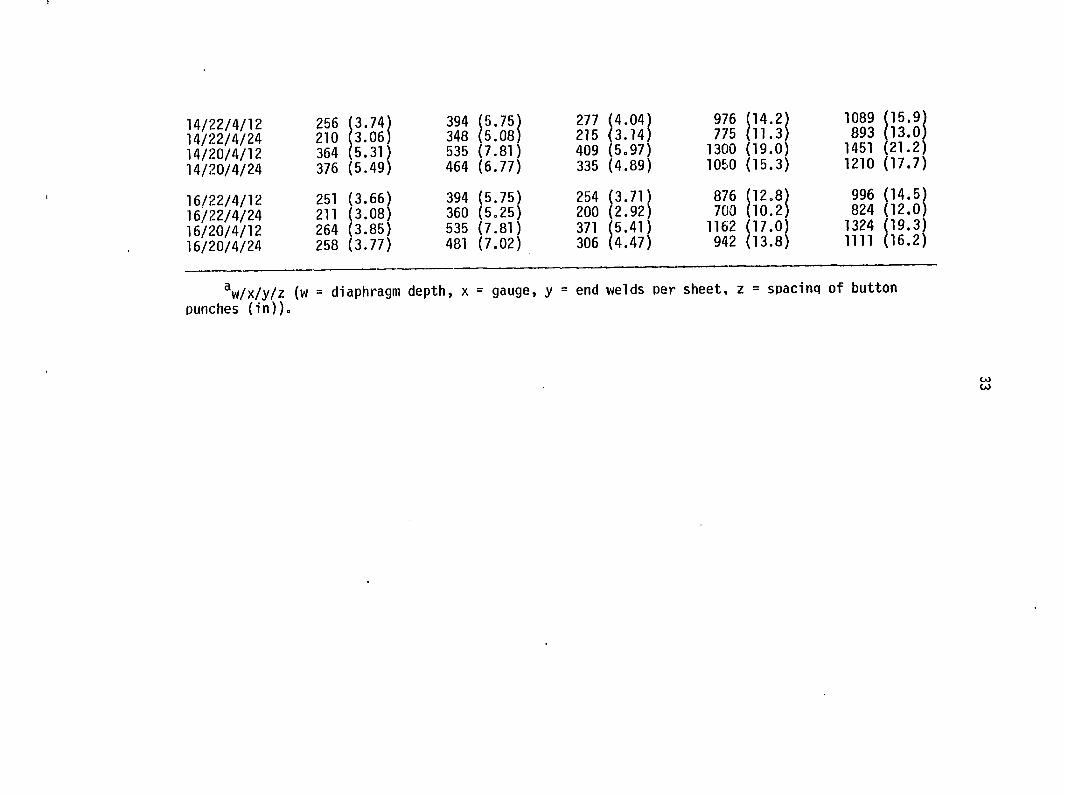
14/22/4/12 14/22/4/24 14/20/4/12 14/20/4/24
16/22/4/12 16/22/4/24 16/20/4/12 16/20/4/24
256 (3.74) 210 (3.06) 364 (5.31) 376 (5.49)
251 (3.66) 211 (3.08) 264 (3.85) 258 (3.77)
394 (5.75) 348 (5.08) 535 (7.81) 464 (6.77)
394 (5.75) 360 (5.25) 535 (7.81) 481 (7.02)
^w/x/y/z (w = diaphragm depth, x = gauge, punches (in)).
277 (4.04) 215 (3.14) 409 (5.97) 335 (4.89)
254 (3.71) 200 (2.92) 371 (5.41) 306 (4.47)
976 (14.2) 775 (11.3)
1300 (19.0) 1060 (15.3)
876 (12.8) 700 (10.2)
1162 (17.0) 942 (13.8)
1089 (15.9) 893 (13.0)
1451 (21.2) 1210 (17.7)
996 (14.5) 824 (12.0)
1324 (19.3) n i l ( 1 6 . 2 )
end welds per sheet, z = spacinq of button
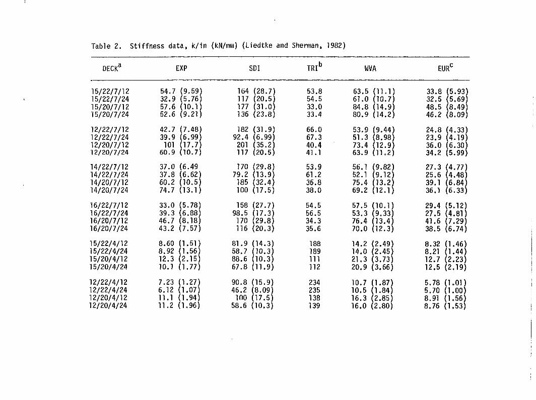
Table 2. Stiffness data, k/in (kN/irmi) (Liedtke and Sherman, 1982)
DECK* EXP SDI TRI^ WVA
LU
15/22/7/12 54.7 (9.59) 164 (28.7) 53.8 63.5 11.1) 33.8 (5.93) 15/22/7/24 32.9 (5.76) 117 (20.5) 54.5 61.0 10.7) 32.5 (5.69) 15/20/7/12 57.6 (10.1 177 (31.0) 33.0 84.8 14.9) 48.5 (8.49) 15/20/7/24 52.6 (9.21) 136 (23.8) 33.4 80.9 14.2) 46.2 (8.09)
12/22/7/12 42.7 (7.48) 182 (31.9) 66.0 53.9 9.44) 24.8 (4.33) 12/22/7/24 39.9 (6.99) 92.4 (6.99) 67.3 51.3 8.98) 23.9 (4.19) 12/20/7/12 101 (17.7) 201 (35.2) 40.4 73.4 12.9) 36.0 (6.30) 12/20/7/24 60.9 (10.7) 117 (20.5) 41.1 63.9 11.2) 34.2 (5.99)
14/22/7/12 37.0 (6.49 170 (29.8) 53.9 56.1 9.82) 27.3 (4.77) 14/22/7/24 37.8 (6.62) 79.2 (13.9) 61.2 52.1 9.12) 25.6 (4.48) 14/20/7/12 60.2 (10.5) 185 (32.4) 36.8 75.4 13.2) 39.1 (6.84) 14/20/7/24 74.7 (13.1) 100 (17.5) 38.0 69.2 12.1) 36.1 (6.33)
16/22/7/12 33.0 (5.78) 158 (27.7) 54.5 57.5 10.1) 29.4 (5.12) 16/22/7/24 39.3 (6.88) 98.5 (17.3) 56.5 53.3 9.33) 27.5 (4.81) 16/20/7/12 46.7 (8.18) 170 (29.8) 34.3 76.4 13.4) 41.6 (7.29) 16/20/7/24 43.2 (7.57) 116 (20.3) 35.6 70.0 12.3) 38.5 (6.74)
15/22/4/12 8.60 (1.51) 81.9 (14.3) 188 14.2 2.49) 8.32 (1.46) 15/22/4/24 8.92 (1.56) 58.7 (10.3) 189 14.0 2.45) 8.21 (1.44) 15/20/4/12 12.3 (2.15) 88.6 (10.3) 111 21.3 3.73) 12.7 (2.23) 15/20/4/24 10.1 (1.77) 67.8 (11.9) 112 20.9 3.66) 12.5 (2.19)
12/22/4/12 7.23 (1.27) 90.8 (15.9) 234 10.7 1.87) 5.78 (1.01) 12/22/4/24 6.12 (1.07) 46.2 (8.09) 235 10.5 1.84) 5.70 (1.00) 12/20/4/12 11.1 (1.94) 100 (17.5) 138 16.3 2.85) 8.91 (1,56) 12/20/4/24 11.2 (1.96) 58.6 (10.3) 139 16.0 2.80) 8.76 (1.53)
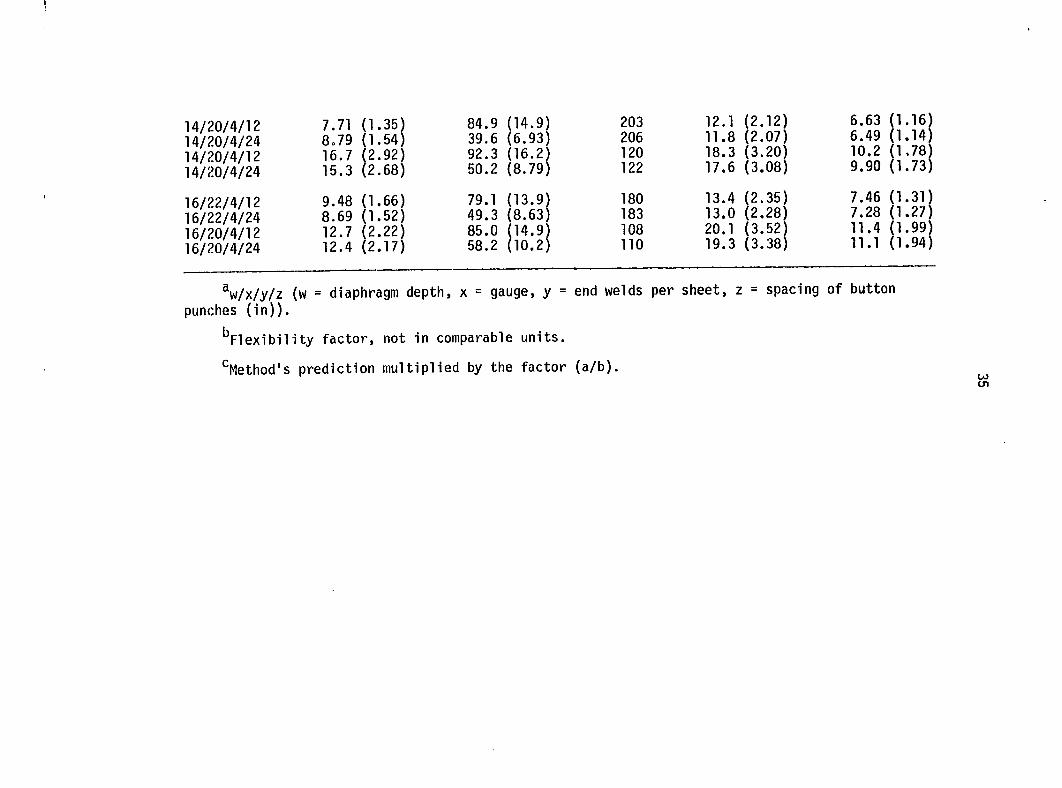
I
14/20/4/12 14/20/4/24 14/20/4/12 14/20/4/24
16/22/4/12 16/22/4/24 16/20/4/12 16/20/4/24
7.71 (1.35) 84.9 8.79 (1.54) 39.6 16.7 (2.92) 92.3 15.3 (2.68) 50.2
9.48 (1.66) 79.1 8.69 (1.52) 49.3 12.7 (2.22) 85.0 12.4 (2.17) 58.2
(8.79)
203 12.1 (2.12) 6.63 206 11.8 (2.07) 6.49 120 18.3 (3.20) 10.2 122 17.6 (3.08) 9.90
180 13.4 (2.35) 7.46 183 13.0 (2.28) 7.28 108 20.1 (3.52) 11.4 110 19.3 (3.38) 11.1
1.99) 1.94)
Vx/y/z (w = diaphragm depth, x = gauge, y = end welds per sheet, z = spacing of button punches (in)).
'^Flexibility factor, not in comparable units.
^Method's prediction multiplied by the factor (a/b). W m
TEST PROCEDURE AND APPARATUS
Thirty-one diaphragms were constructed and tested. Fifteen
diaphragms were constructed of Strongpanel, a product of Granite City
Building Products, with nominal dimensions of 7 ft. 8 in. x 12 ft. The
remaining 16 diaphragms were constructed of Grandrib 3, a product of
Fabral, with nominal dimensions of 9 ft. x 12 ft. Each diaphragm
was constructed with three sheets of steel fastened to seven purlins
according to manufacturer's recommended fastener pattern. The 31
diaphragms were tested as centilever diaphragms. The following will
detail test equipment and procedures and give construction details of
the diaphragms.
Test Equipment - General
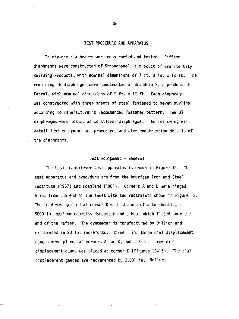
The basic cantilever test apparatus is shown in Figure 12. The
test apparatus and procedure are from the American Iron and Steel
Institute (1967) and Hoagland (1981). Corners A and B were hinged
6 in. from the end of the sheet with the restraints shown in Figure 13.
The load was applied at corner D with the use of a turnbuckle, a
5000 lb. maximum capacity dynometer and a boot which fitted over the
end of the rafter. The dynometer is manufactured by Dillion and
calibrated in 20 lb. increments. Three 1 in. throw dial displacement
gauges were placed at corners A and B, and a 3 in. throw dial
displacement gauge was placed at corner D (Figures 13-15). The dial
displacement gauges are incremented by 0.001 in. Rollers
37
%
nv
Di recti on of
corrugation
1
ô
Figure 1 2 . Cantilever diaphragm test arrangement
Figure 13. Corner B placement of dial deflection gauges for diaphragms 1-14
Figure 14. Corner A placement of dial deflection gauge
3g
Figure 15. Load apparatus and dial deflection gauge at corner D
Figure 16. Corner B placement of dial deflection gauges for diaphragms 15 and la-16a
42
were placed under corners C and D to reduce friction between the
floor and the diaphragm frame.
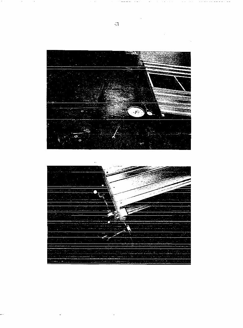
The 1 in. throw dial displacement gauge at corner B measuring the
deflection parallel to the corrugation was moved from the rafter to
the purlin (Figure 16). The placement of the displacement gauge was
originally done for comparison to Hoagland's (1981) results. However,
the placement (Figure 13) includes the purlin rafter connection slip
(Figure 11), which is not included in the placement of the 3 in. throw
dial displacement gauge (Figure 14). It was decided that the slip
measurements parallel to the corrugations should include the same
components. Therefore, the 1 in. throw dial displacement gauge was
moved to the purlin, as shown in Figure 16. The first 14 diaphragms
were tested with the dial displacement gauges placed as shown in
Figure 13, diaphragms 1-14, and the remaining 17 diaphragms were
tested with the dial displacement gauges placed as shown in Figure 16,
diaphragms 15 and la-T6a.
Test Equipment - Special
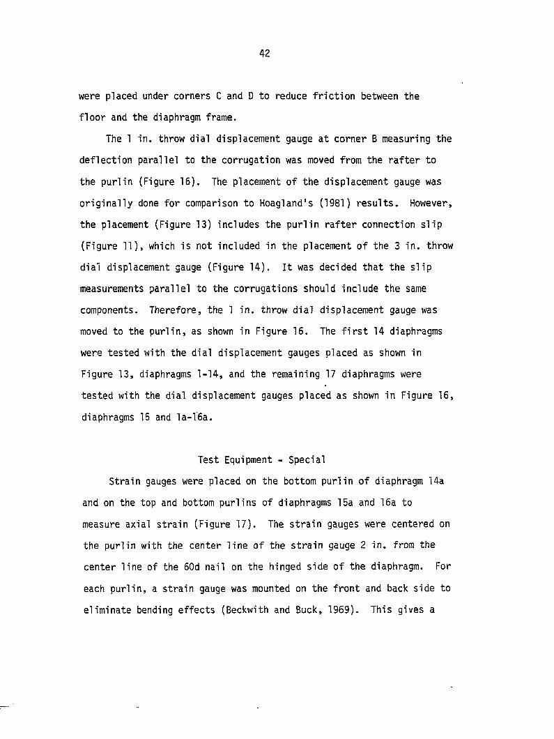
Strain gauges were placed on the bottom purlin of diaphragm 14a
and on the top and bottom purlins of diaphragms 15a and 16a to
measure axial strain (Figure 17). The strain gauges were centered on
the purlin with the center line of the strain gauge 2 in. from the
center line of the 50d nail on the hinged side of the diaphragm. For
each purlin, a strain gauge was mounted on the front and back side to
eliminate bending effects (Beckwith and Buck, 1969). This gives a
Figure 17. Strain gauge placed on purlin
Figure 18. Strain gauge rosette mounted on the steel sheeting
45
bridge constant of 2 (Appendix B).
The strain gauges used were CEA-06-500UW-120 from Measurements
Group, IncJ. Their selection was based on the recommendations of the
company (Measurements Group, Inc., 1983a). The wood surface was sanded
with No. 200 sandpaper and then, a layer of epoxy was applied. After
this, the epoxy surface was prepared, the strain gauges were mounted
and lead wires were attached according to company instructions
(Measurements Group, Inc., 1976; 1979; 1983b).
Strain gauge rosettes, CEA-06-125UR-120, were also mounted on
the steel of diaphragms 15a and 16a (Figure 18). On diaphragm 15a,
two rosettes were mounted 6 9/16 in. from the steel on side BC. One
rosette was 5 in. in and the other was 59 in. in from the edge of the
steel on side AB (Figure 19). Three rosettes were mounted on
diaphragm 16a. Two rosettes were mounted 6 9/16 in. in from the edge
of the steel on side BC with one rosette 5 in. in from side AB of the
steel and the other was 5 in. in from the edge of the steel on side
CD. The third rosette was 72 in. down from edge of the steel on
side BC and 59 in. from the edge of the steel on side AB (Figure 20).
The rosettes were selected, mounted, and lead wires attached
according to company literature cited for strain gauges mounted on
the purlins. The strain for the strain gauges mounted on the purlins
or the rosettes was read using a Measurements Group, Inc. P-3500
portable strain indicator and a switch (Figure 21). The temperature
varied by 1°F during the diaphragm tests with strain gauges.
^No endorsement of products is intended.
46
4 5"
6 9/16 4-
59"-
!
Figure 19. Location of strain gauge rosettes on diaphragm 15a
47
6 9/16
59"-
-4"
+
Figure 20. Location of strain gauge rosettes on diaphragm 16a
Figure 21. Portable strain indicator, P-3500, and switch
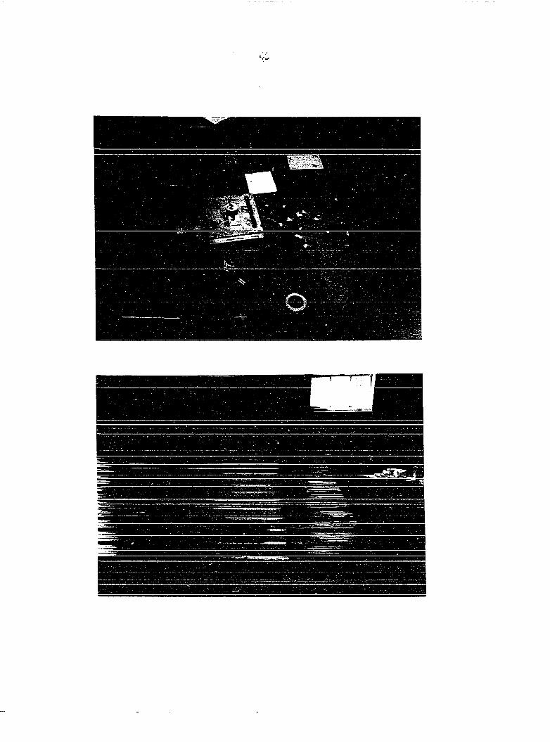
Figure 22. Brittle coating on diaphragm, test bars, and thermometer
50
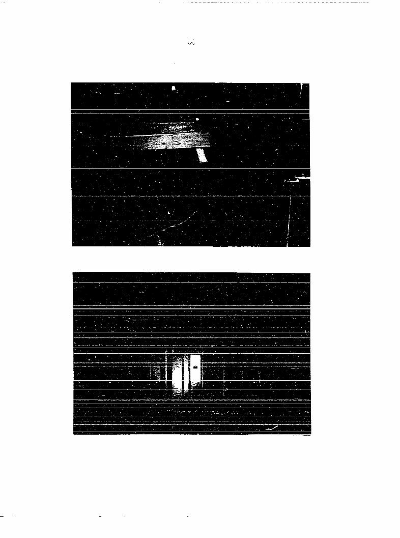
Diaphragm 15a had brittle coating applied to it for one loading.
The brittle coat, Tens-Lac TL500-75-A\ was selected and applied
according to Measurement Group, Inc. (1982). An undercoat was also
applied. The brittle coating was applied the entire width of the
diaphragm steel for a depth of 24 in. in from the edge of the steel on
side BC (Figure 22). At the same time that the undercoat and brittle
coat were applied to the steel, eight test bars were coated. The test
bars were 1 in. wide x 12 in. long x 0.25 in. thick. The test bars were
tested to calibrate the brittle coating in a calibrator. Two test bars
were tested at the beginning of the test, two at the end of the test,
two at a load of 300 lb., and two at a load of 600 lb. A flashlight
was held at an oblique angle to the surface of the steel to find the
cracks in the brittle coat. The cracks were then marked with a black
felt tip pen (Dally and Riley, 1965) (Figure 23). The temperature at
the beginning of the test was 67°F, rising to 68°F at the end of the
test. The thermometer was placed on top of the steel in the vicinity
of the brittle coating and the test bars (Figure 22). The room
temperature was maintained between 78°F and 85°F for the 24-hour
drying period of the brittle coating.
Diaphragm Framing
There were six framing systems that were used for the tests. The
framing systems all had two 2x8 rafters of structural No. 2 grade
Spruce-Pine-Fir (SPF) and seven 2x4 purlins of standard or better
(Std-Btr) grade SPF. The rafters were placed 90.5 in. on-center for
^No endorsement of product is intended.
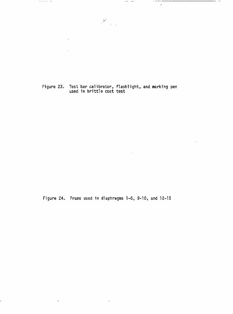
Figure 23. Test bar calibrator, flashlight, and marking pen used in brittle coat test
Figure 24. Frame used in diaphragms 1-6, 9-10, and 12-15
53
Strongpanel sheeting and 108.25 in. on-center for the Grandrib 3
sheeting. The purlins extended 2.75 in. past the center line of the
rafter on each side. The purlins were either placed on edge or flat.
The purlins placed on edge were affixed to each of the rafters with a
60d nail 2.75 in. in from the end of the purlin and centered on the
rafter and two lOd toe nails. The purlins which were .placed flat
(diaphragms 12a and 13a) on the rafter were affixed with two lOd nails
2.75 in. in from the end of the purlin and centered on the rafter
(Figure 25). The 60d nails were driven into predrilled holes 3/16 in.
in diameter (National Forest Products Association, 1986a).
Diaphragms 1-6, 9-10, and 12-15 had their purlins placed on edge.
The rafters were nominally 12 ft. long with lengths varying from
144 1/8 in. to 144 3/8 in. This left an edge distance from the
center line of the 60d nail to the end of the rafter of 13/16 in. to
15/16 in. (Figure 24). The purlins were spaced 23.75 in. in on-center.
Diaphragms la-lla and 14a-16a were built the same as above, except
that the rafters were nominally 14 ft. long. Their lengths varied
from 168 1/8 in. to 168 3/8 in., giving a distance from the center line
of the 60d nail to the end of the rafter of 12 13/16 in. to 12 15/16 in.
(Figure 26).
Diaphragms 7, 8, and 11 were built with the same rafter as
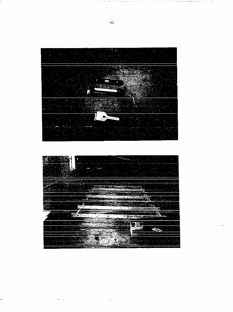
diaphragms 1-6, 9-10, and 12-15. The edge purlins were recessed in
from the edge of the steel (Figure 27). Diaphragm 7 had a recess of
6 in. with a purlin spacing of 21.75 in. on-center, diaphragm 8 had a
recess of 3 in. with a purlin spacing of 22.75 in. on-center, and
54
two lOd toe nails and one 60d nail
Rafter Purlin
Purlin on edge
two lOd nails
M |— 7/8"
Purlin flat
Figure 25. Purlin to rafter connections
Figure 26. Frame used in diaphragms la-lla and 14a-16a
Figure 27. 12 in. recess of edge purlin of diaphragm 11
56
57
diaphragm 11 had a recess of 12 in. with a purlin spacing of 19.75 in.
on-center.
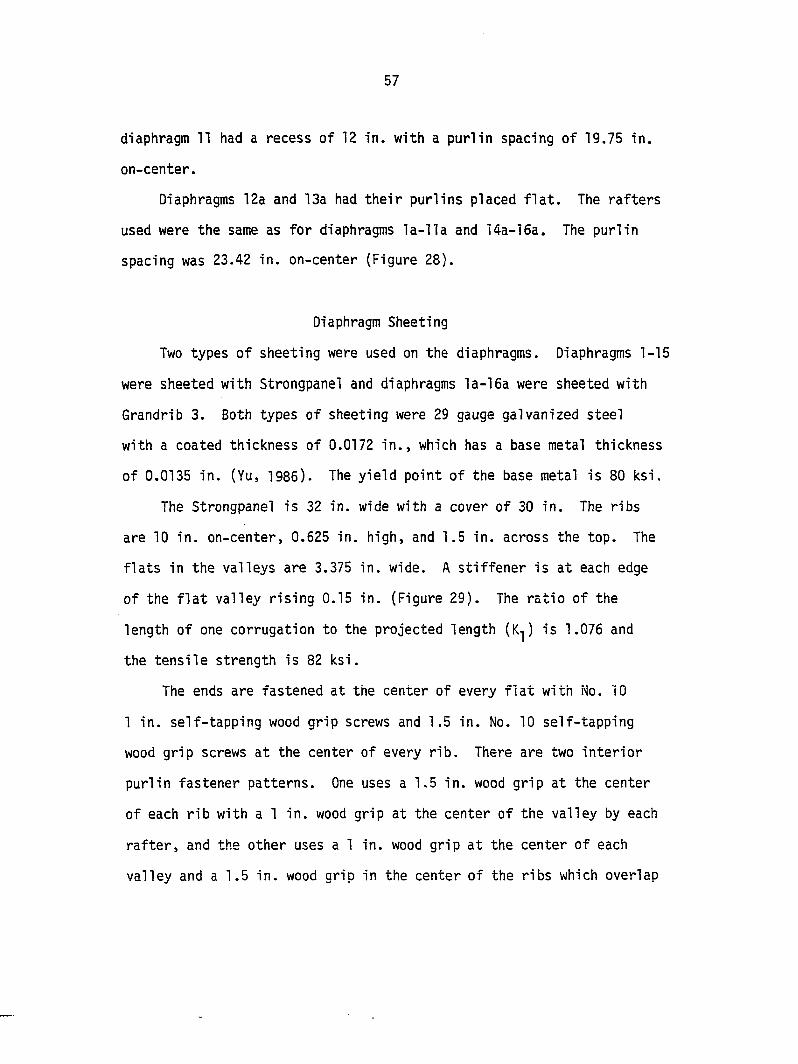
Diaphragms 12a and 13a had their purlins placed flat. The rafters
used were the same as for diaphragms la-lla and 14a-16a. The purlin
spacing was 23.42 in. on-center (Figure 28).
Diaphragm Sheeting
Two types of sheeting were used on the diaphragms. Diaphragms 1-15
were sheeted with Strongpanel and diaphragms la-16a were sheeted with
Grandrib 3. Both types of sheeting were 29 gauge galvanized steel
with a coated thickness of 0.0172 in., which has a base metal thickness
of 0.0135 in. (Yu, 1985). The yield point of the base metal is 80 ksi.
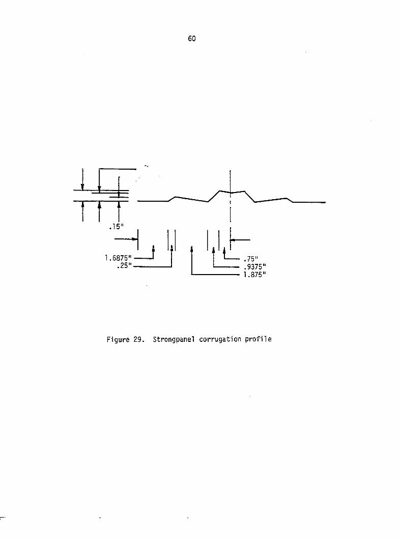
The Strongpanel is 32 in. wide with a cover of 30 in. The ribs
are 10 in. on-center, 0.625 in. high, and 1.5 in. across the top. The
flats in the valleys are 3.375 in. wide. A stiffener is at each edge
of the flat valley rising 0.15 in. (Figure 29). The ratio of the
length of one corrugation to the projected length (K^) is 1.076 and
the tensile strength is 82 ksi.
The ends are fastened at the center of every flat with No. 10
1 in. self-tapping wood grip screws and 1.5 in. No. 10 self-tapping
wood grip screws at the center of every rib. There are two interior
purlin fastener patterns. One uses a 1.5 in. wood grip at the center
of each rib with a 1 in. wood grip at the center of the valley by each
rafter, and the other uses a 1 in. wood grip at the center of each
valley and a 1.5 in. wood grip in the center of the ribs which overlap
Figure 28. Frame in diaphragms 12a and 13a
60
n .15"
1.6875" .25".
J } L .75" .9375" 1.875"
Figure 29. Strongpanel corrugation profile
61
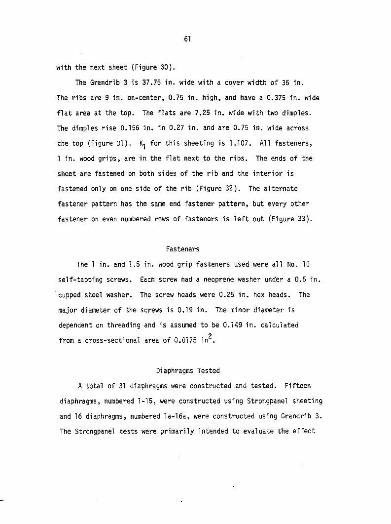
with the next sheet (Figure 30).
The Grandrib 3 is 37.75 in. wide with a cover width of 36 in.
The ribs are 9 in. on-center, 0.75 in. high, and have a 0.375 in. wide
flat area at the top. The flats are 7.25 in. wide with two dimples.
The dimples rise 0.156 in. in 0.27 in. and are 0.75 in. wide across
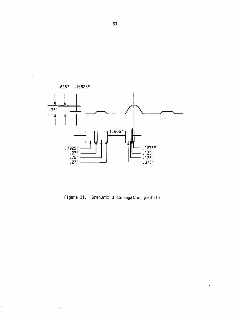
the top (Figure 31). for this sheeting is 1.107. All fasteners,
1 in. wood grips, are in the flat next to the ribs. The ends of the
sheet are fastened on both sides of the rib and the interior is
fastened only on one side of the rib (Figure 32). The alternate
fastener pattern has the same end fastener pattern, but every other
fastener on even numbered rows of fasteners is left out (Figure 33).
Fasteners
The 1 in. and 1.5 in. wood grip fasteners used were all No. 10
self-tapping screws. Each screw had a neoprene washer under a 0.5 in.
cupped steel washer. The screw heads were 0.25 in. hex heads. The
major diameter of the screws is 0.19 in. The minor diameter is
dependent on threading and is assumed to be 0.149 in. calculated
2 from a cross-sectional area of 0.0175 in .
Diaphragms Tested
A total of 31 diaphragms were constructed and tested. Fifteen
diaphragms, numbered 1-15, were constructed using Strongpanel sheeting
and 16 diaphragms, numbered la-16a, were constructed using Grandrib 3.
The Strongpanel tests were primarily intended to evaluate the effect
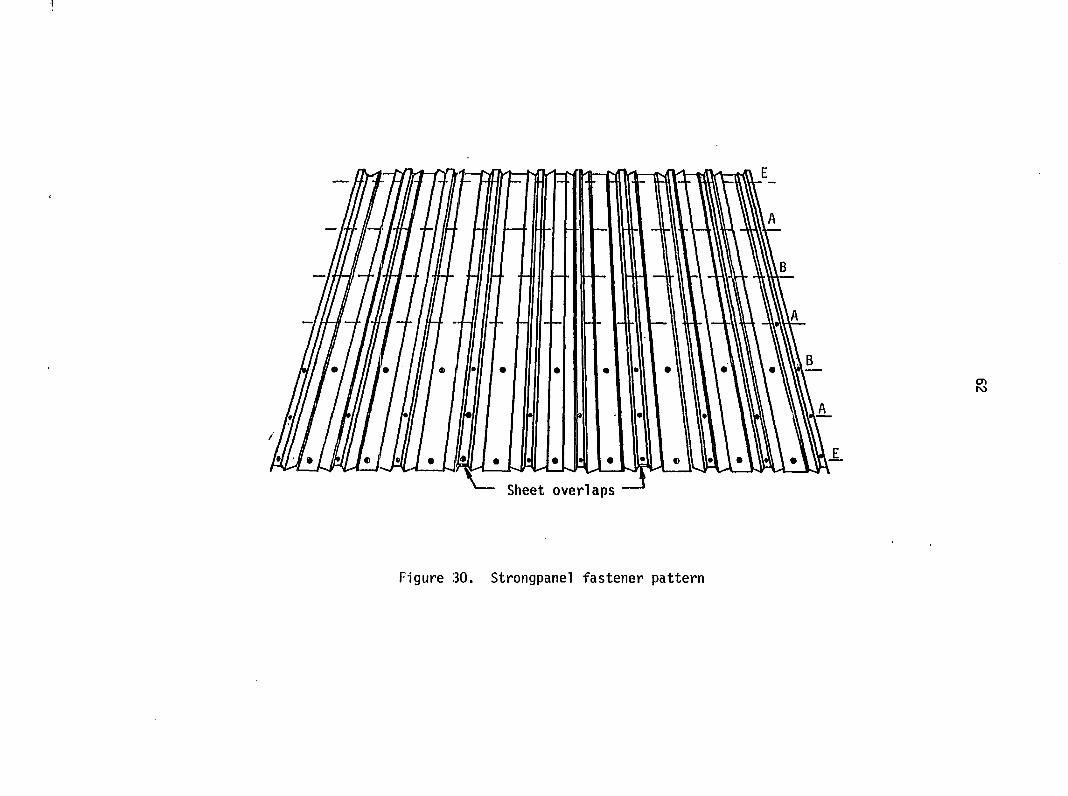
Figure 30. Strongpanel fastener pattern
63
.625" .15625"
Figure 31. Grandrib 3 corrugation profile
64
h
Ul. Sheet overlaps
Figure 32. Grandrib 3 fastener pattern
55
U «il» «_5 • L ».
Figure 33. Grandrib 3 alternate fastener pattern used with diaphragms 9a-lla
66
of openings and the effect of recessing the purlins in from the edge
of the steel on diaphragm stiffness. The Grandrib 3 tests were
intended to look at the effects of the following on diaphragm
stiffness:
1. Diaphragms made of more than one sheet in its length.
2. Alternate interior sheet to purlin fastener pattern.
3. Purlins placed flat.
4. Sheet and edge purlin strains.
A brief description of the tests will be given for the Strongpanel
and Grandrib 3.
Strongpanel Tests
Diaphragms 1 and 15 are control diaphragms. They have no openings
in them and the purlins are not recessed. The only difference between
them is that the displacement gauge at corner B measuring
displacement parallel to the load was placed against the rafter for
diaphragm 1 and against the purlin for diaphragm 15 (Figures 11 and 12).
This will give an estimate of the rafter to purlin connection slip on
one side of the diaphragm.
Diaphragms 7, 8, and 11 had the edge purlins recessed in 6 in.,
3 in., and 12 in., respectively, from the end of the steel (Figure 34).
This was done to see if the steel extending beyond the edge purlin
was still effective.
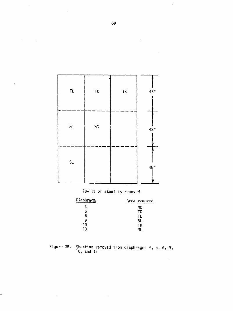
Diaphragms 4-6, 9, 10, and 13 have approximately 11 % of their
sheet steel removed. The area removed was the width of one sheet by
67
(see note)
92"
Tnçot
(see note)
NOTE: 3" inset panel has edge purlins inset 3" from edge of steel. There are seven purlins at 22.75" o-c.
6" inset panel has edge purlins inset 6" from edge of steel. There are seven purlins at 21.75" o-c.
12" inset panel has edge purlins inset 12" from edge of steel. There are seven purlins at 19.75" o-c.
Figure 34. Diaphragms 7, 8, and 11 recessing
68
48 in. The position of the opening varied for each test (Figure 35).
The tests are to determine the effect on diaphragm stiffness of this
size of hole and location. It is assumed that the portion of the
steel sheeting not removed below the diagonal would have the same
effect as the portions that were removed above the diagonal by symmetry.
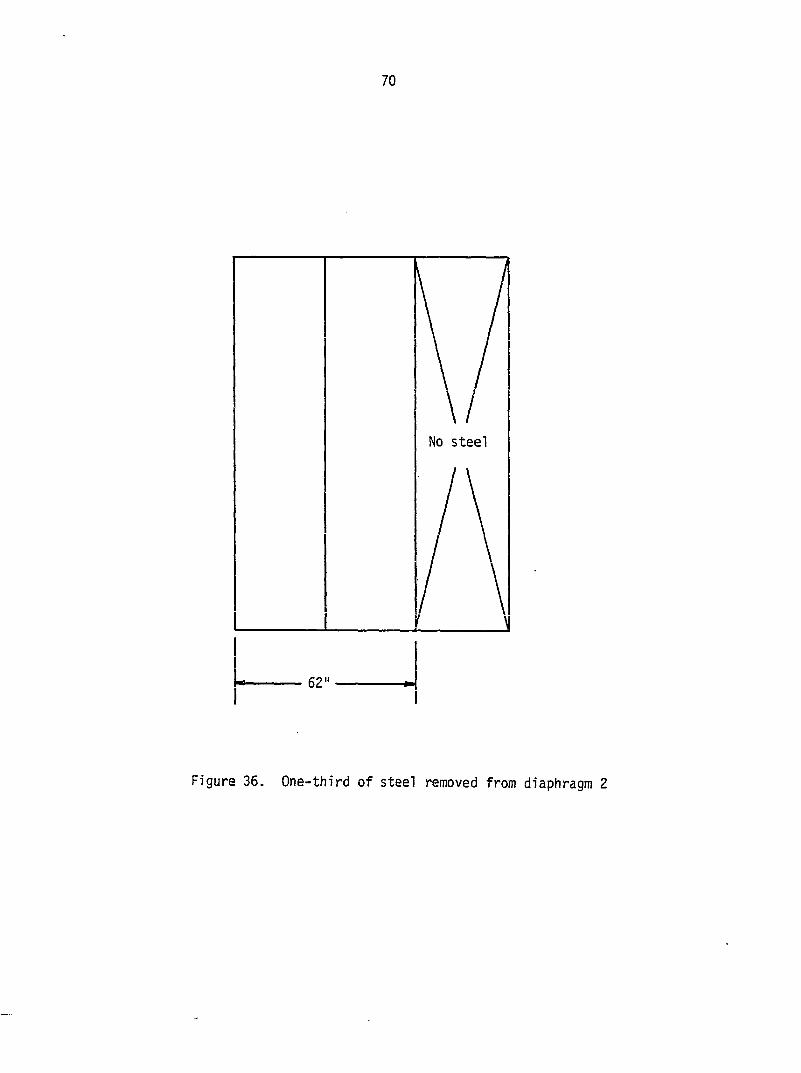
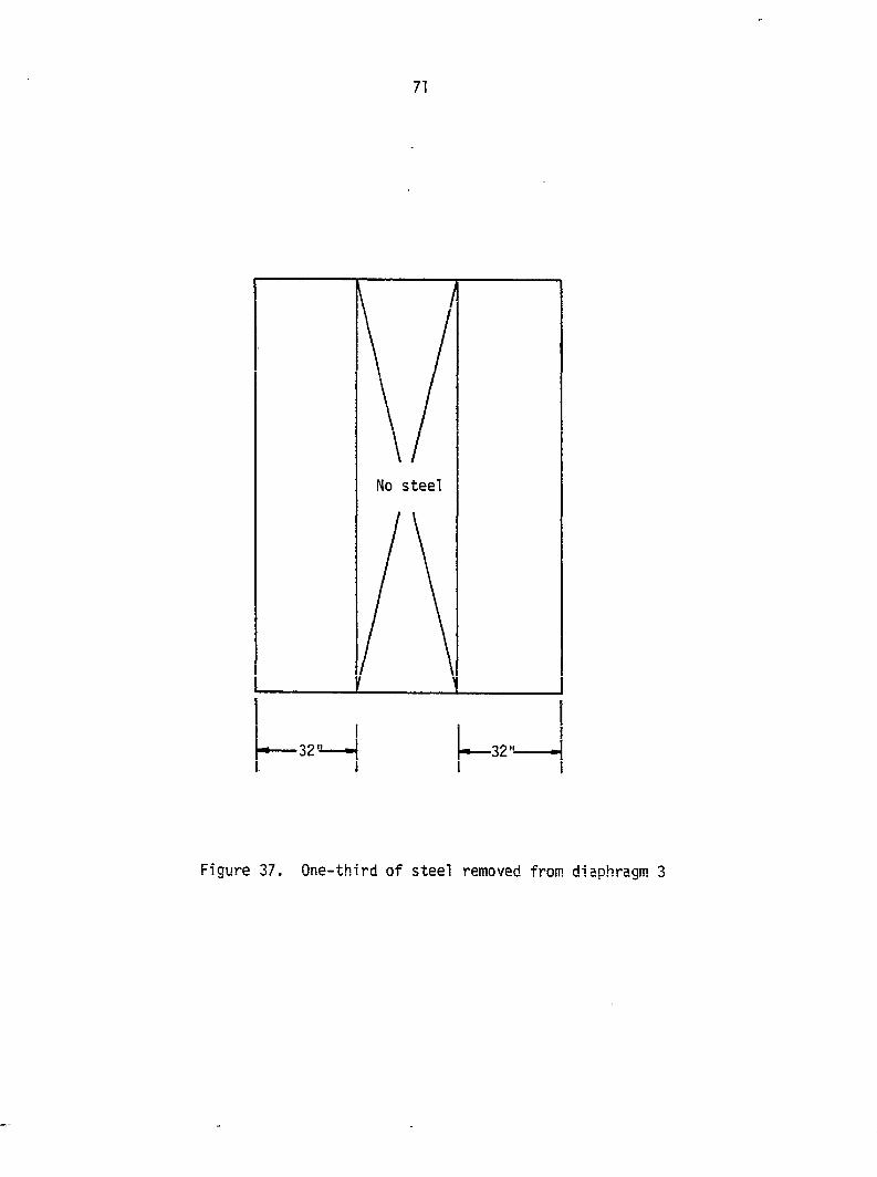
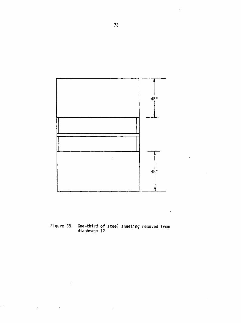
Diaphragms 2, 3, 12, and 14 have about 33% of the steel sheeting
removed. Diaphragm 2 has one sheet removed on the load side, while
diaphragm 3 has the middle sheet removed (Figures 36 and 37).
Diaphragm 12 had the middle 48 in. removed from all sheets and
diaphragm 14 had the upper 48 In. removed from all sheets (Figures 38
and 39). The effect on diaphragm stiffness and behavior of the
unsheeted portion of the frame were evaluated.
Grandrib 3 Tests
Diaphragms la, 4a, and 14a are control diaphragms. The only
difference between them is that diaphragm 14a had a one-half strain
gauge bridge attached to the lower edge purlin to measure axial strain
(Figure 17). The fastener pattern is shown in Figure 32.
Diaphragms 2a, 3a, and 5a-8a were made up of more than one sheet
in the length of the diaphragm. Diaphragms 2a, 5a, and 8a were made
up of two sheets. The bottom sheet was 72 in. long and the top sheet
was 78 in. long, which provided a 5 in. overlap (Figure 40).
Diaphragms 3a, 6a, and 7a were made up of three sheets. The bottom
sheet was 48 in. long; the middle sheet and top sheet were 54 in. long.
69
TL TC TR
ML MC
BL
48" I
48"
48"
10-11% of steel is removed
uiaphraqtn
4 5 6 9
10 13
Area removed
MC TC TL 8L TR ML
Figure 35. Sheeting removed from diaphragms 4, 5, 6, 9, 10, and 13
70
No steel
62
Figure 36. One-third of steel removed from diaphragm 2
71
\ / \ / No steel
j-—32"
Figure 37. One-third of steel removed from diaphragm 3
72
~r
48"
Figure 38. One-third of steel sheeting removed from diaphragm 12
73
48"
96"
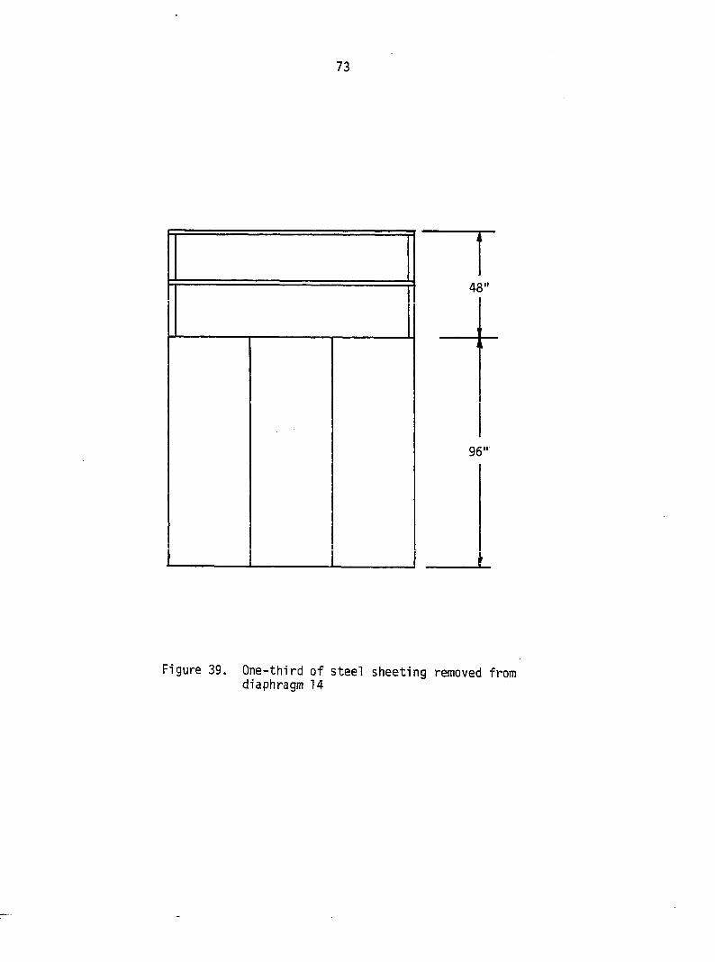
Figure 39. One-third of steel sheeting removed from diaphragm 14
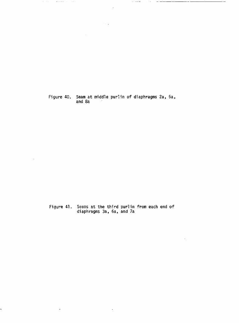
Figure 40. Seam at middle purlin of diaphragms 2a, 5a, and 8a
Figure 41. Seams at the third purlin from each end of diaphragms 3a, 6a, and 7a
76
This provided for the 6 in. overlap at each joint (Figure 41). At each
joint, the fastener pattern used is labeled "E" on Figure 17. The
fasteners passed through both sheets at the joint.
Diaphragms 9a-lla are the same as the control diaphragms, except
that they used an alternate fastener pattern (Figure 33). The effect
of a reduced number of interior sheet to purlin fasteners is evaluated.
Diaphragms 12a and 13a had their purlins laid flat (Figure 42).
Fastening pattern is the same, as shown in Figure 32, for the sheet
to purlin fasteners. The different framing is what was assessed and
its details are shown in Figures 23 and 28.
Diaphragms 15a and 16a were constructed identical to the control
diaphragms la, 4a, and 14a (Figure 32). Both diaphragms had a one-half
strain gauge bridge mounted on the top and bottom edge purlins
(Figure 17). Diaphragm 15a had a brittle coat applied to it
(Figure 22). Diaphragm 15a had a strain gauge rosette placed on the
top left and top middle sections, while diaphragm 16a had a strain
gauge rosette placed on the top left, top right, and middle sections
(Figures 18-20). Because of all the measurements being taken, diaphragm
15a was loaded three times to 960 lbs. and then to failure and
diaphragm 16a was loaded once to 960 lbs. and then to failure.
Measurements taken for each loading of diaphragm 15a are:
1. Top and bottom edge purlin axial strain.
2. Top and bottom edge purlin axial strain.
3. Bottom edge purlin axial strain and brittle coat.
4. Strain in sheeting on the top left and top middle sections.
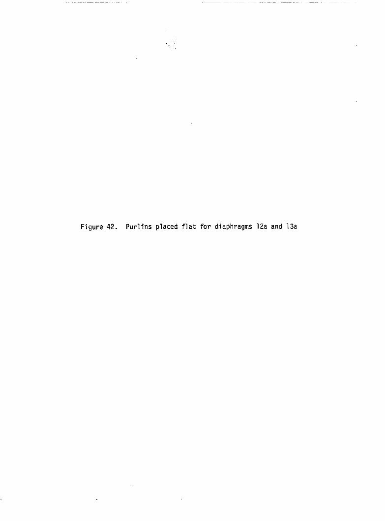
Figure 42. Purlins placed flat for diaphragms 12a and 13a
79
Measurements taken for each loading of diaphragm 16a were:
1. Strain in sheeting on the top left, top right, and middle
sections.
2. Top and bottom edge purlin axial strain.
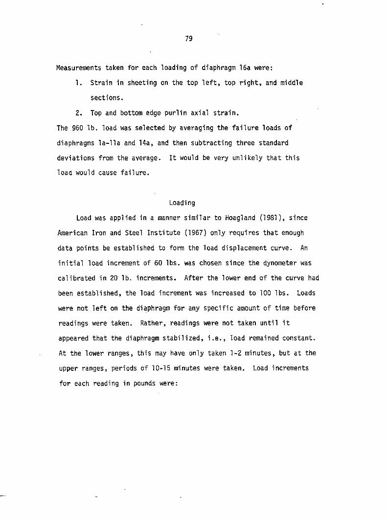
The 960 lb. load was selected by averaging the failure loads of
diaphragms la-lla and 14a, and then subtracting three standard
deviations from the average. It would be very unlikely that this
load would cause failure.
Loadi ng
Load was applied in a manner similar to Hoagland (1981), since
American Iron and Steel Institute (1967) only requires that enough
data points be established to form the load displacement curve. An
initial load increment of 60 lbs. was chosen since the dynometer was
calibrated in 20 lb. increments. After the lower end of the curve had
been established, the load increment was increased to 100 lbs. Loads
were not left on the diaphragm for any specific amount of time before
readings were taken. Rather, readings were not taken until it
appeared that the diaphragm stabilized, i.e., load remained constant.
At the lower ranges, this may have only taken 1-2 minutes, but at the
upper ranges, periods of 10-15 minutes were taken. Load increments
for each reading in pounds were:
80
1. 0 10. 540 19. 1100
2. 60 n. 600 20. 1200
3. 120 12. 660 21. 1300
4. 180 13. 720 22. 1400
5. 240 14. 780 23. 1500
6. 300 15. 840 24. 1600
7. 360 16. 900 25. 1700
8. 420 17. 960 26. 1800
9. 480 18. 1020 27. 1900
28. 2000
If failure occurred before 2000 lbs., loading was stopped. Failure
was defined as when the diaphragm allowed the load to drop abruptly
and the diaphragm would not take loading back to the point where the
abrupt drop occurred. For diaphragms 15a and 16a, the loading followed
the same increment to 960 lbs. and then was released back to 0. Prior
to the start of loading, each diaphragm was loaded to the 160 to 200 lb.
range or 0.01 in. gross deflection at the load corner. This was
intended to settle the frame into the supports.
Calibration
The dynometer and the displacement gauges were calibrated with the
aid of Doug Wood, Research Associate, Department of Civil Engineering,
Iowa State University. The dynometer was loaded on the Satech 400 HVL
test frame in the structures lab of Town Engineering Building.
81
The load indicated by the Satech 400 HVL test frame was taken as the
true reading and an adjustment equation was developed to adjust the
dynometer reading to the Satech 400 HVL test frame reading (Appendix C).
The displacement gauges were calibrated against a Schoevitz calibrator
for transducers. The maximum difference between the Schoevitz
calibrator and a displacement gauge was 0.004 in. It was decided that
this discrepancy was due to the support which held the displacement
gauge arm not being parallel to the calibrator. No correction factors
were deemed necessary.
Two frames were loaded without sheeting to check the rolling
resistance of the frames (Figure 28). One frame was with the purlins
placed flat and the other was with the purlins on edge (Figure 26).
Neither frame recorded a rolling resistance of 10 lbs. This would
require a failure load of 500 lbs. or less before a correction for the
rolling resistance of the frame is required (American Iron and Steel
Institute, 1967).
Purlin Modulus of Elasticity
It was decided that the modulus of elasticity of the purlins
needed to be determined for the lumber being used rather than using
values from the National Forest Products Association (1986b) because
of the large variability in the modulus elasticity values of a species
of wood (Hoyle, 1978). After the first 17 diaphragms had been tested,
five purlins were selected at random. From each of the five selected
purlins, a relatively clear 50 in. length was cut. A 0.75 in. diameter
82
hole was drilled 12 in. in from one end and centered, and a 0.625 in.
hole was drilled 2 in. in from the other end and centered. The dynometer
was attached to the 2 in. hole and the section was clamped tight in a
support at the other hole (Figure 43). A 3 in. displacement gauge
measured the movement at the load point, and a 1 in. displacement gauge
measured the movement of the free end. The load increment in pounds
for all five tests was:
1. 40
2. 60
3. 120
4. 160
The shear modulus for the wood was assumed to be 1/16 the modulus of
elasticity (Gurfinkel, 1973). The basic concept of the test is also
from Gurfinkel.
Figure 43. Test apparatus for modulus of elasticity of the purlins
o*-t
85
RESULTS AND DISCUSSION
Deflection load plots for the diaphragms are shown in
Figures 46-49, 53-54, and 56-61. The curves show shear deflection
versus shear load. The shear load is the load applied at corner D.
The shear deflection is adjusted for the support movement and any
rafter movement at corners A and B by the AISI (1967) equation:
At = Ai - - |t- (Ag + Ag)
where Ay = gross deflection at corner D, in.,
A"! = dial deflection gauge reading 1, in.,
Ag = dial deflection gauge reading 2, in.,
A^ = dial deflection gauge reading 3, in.,
A^ = dial deflection gauge reading 4, in.,
a' = distance normal to corrugation between deflecting
gauges 1 and 4, in., and
b' = distance between deflection gauges 2 and 3 parallel
to corrugation, in.
The shear deflection of the diaphragm is then found by subtracting
the bending deflection:
As = Ay - Ab
where A^ = shear deflection at corner D, in., and
Aj^ = bending deflection at corner D, in.
86
Diaphragms 1-14 are further adjusted for the movement between the
rafters and purlins. It is assumed that the shear force divides equally
between the purlins. The rafter-purlin connector stiffness used was
7000 lb/in. (Boone, 1987).
The bending deflection was found by:
^b = P *3/3 Ep (3)
where P = load applied at corner D, lb.,
a = width of diaphragm perpendicular to corrugations, in.,
2 Ep = modulus of elasticity of edge purlins, lb/in ,
I = second moment of inertia of edge purlins about
2 4 center line of diaphragm, I = 2A(b/2) , in ,
2 A = cross-sectional area of edge purlin, in , and
b = length of diaphragm parallel to corrugations, in.
The above is based on the assumption that the force perpendicular to
the corrugations is carried by the edge purlins only. This is also
in accordance with the American Iron and Steel Institute (1967). This
correction term would only be about 5% of the total deflection for the
widest diaphragms at the initial stiffness, and it decreases from there.
Modulus of Elasticity of Edge Purlins
The results of the purlin modulus of elasticity tests are given
in Table 3. The modulus of elasticity was determined from the
relationship:
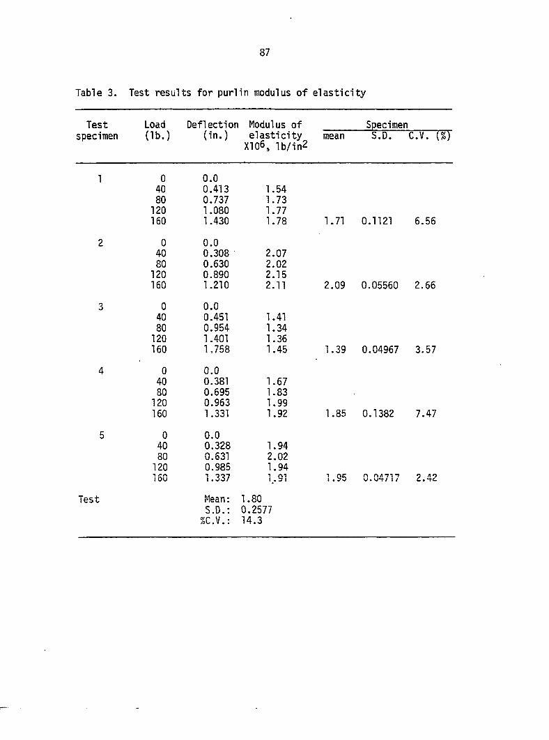
Table 3. Test results for purlin modulus of elasticity
Test Load Deflection Modulus of Specimen specimen (lb.) (in.) elasticity mean S.D. C.V. (%)
XI06, lb / in 2
1 0 40 80
120 160
0.0 0.413 0.737 1.080 1.430
1.54 1.73 1.77 1.78 1.71 0.1121 6.56
2 0 40 80
120 160
0.0 0.308 0.630 0.890 1.210
2.07 2.02 2.15 2.11 2.09 0.05560 2.66
3 0 40 80
120 160
0.0 0.451 0.954 1.401 1.758
1.41 1.34 1.36 1.45 1.39 0.04967 3.57
4 0 40 80
120 160
0.0 0.381 0.695 0.963 1.331
1.67 1.83 1.99 1.92 1.85 0.1382 7.47
5 0 40 80
120 160
0.0 0.328 0.631 0.985 1.337
1.94 2.02 1.94 '.•31 1.95 0.04717 2.42
Test Mean: S.D.;
%C.V.:
1.80 0.2577 14.3
88
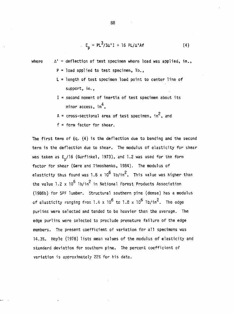
. Ep = PL^/3A'I + 16 PL/A'Af (4)
where A' = deflection of test specimen where load was applied, in.,
P = load applied to test specimen, lb.,
L = length of test specimen load point to center line of
support, in.,
I = second moment of inertia of test specimen about its
. 4 minor access, in ,
2 A = cross-sectional area of test specimen, in , and
f = form factor for shear.
The first term of Eq. (4) is the deflection due to bending and the second
term is the deflection due to shear. The modulus of elasticity for shear
was taken as Ep/15 (Gurfinkel, 1973), and 1.2 was used for the form
factor for shear (Gere and Timoshenko, 1984). The modulus of c 2
elasticity thus found was 1.8 x 10 lb/in . This value was higher than fi p
the value 1.2 x 10 lb/in in National Forest Products Association
(1985b) for SPF lumber. Structural southern pine (dense) has a modulus
of elasticity ranging from 1.4 x 10^ to 1.8 x 10^ Ib/in^. The edge
purlins were selected and tended to be heavier than the average. The
edge purlins were selected to preclude premature failure of the edge
members. The present coefficient of variation for all specimens was
14.3%. Hoyle (1978) lists mean values of the modulus of elasticity and
standard deviation for southern pine. The percent coefficient of
variation is approximately 22% for his data.
89
Diaphragm Computer Analysis
The diaphragms were analyzed using a plane truss/frame analysis
program. The analog used for diaphragms 1-11, 13, and 15 is shown
in Figure 44, and the analog used for diaphragms la-16a is shown in
Figure 45. The cross-sectional area and the minor axis moment of
inertia of the purlins are lumped together at the edge members. The
sheeting is represented by the diagonal truss members. The members
forming the rectangular framing around the diagonal truss members which
connect to the supports are made very rigid and are pinned at both ends.
The diagonal truss members have a second moment of inertia of 0.0 and
their cross-sectional area can be found by Davies' (1977) equation:
A = b t G'Jl^/pEh^ (5)
2 where A = cross-section area of diagonal member, in ,
b = length of diaphragm being modeled parallel to the
corrugations, in.,
t = uncoated thickness of steel sheet, in.,
I = length of diagonal member in the analog, in.,
E = modulus of elasticity of diagonal member in the analog,
Ib/in^,
h = length of rectangular frame member of around diagonal
truss members parallel to corrugations, in.,
p = pitch of sheet purlin fasteners, in., and
2 G' = effective shear modulus of diaphragm sheeting, lb/in .
Four purlins
Spring representing row of
fastener on four purlins
Rigid frame member
Spring representing
sheeting Rigid
framing around sheeting
Three purlins
Figure 44. Analog for Strongpanel sheeting used in computer analysis
-< -
Spring representing sheeting
Seven purlins
Springs representing rows of
fasteners
Rigid framing around sheeting
Figure 45. Analog of Grandrib 3 sheeting used in computer analysis
92
The effective shear modulus has been defined by several investigators,
but for consistency, Davies and Bryan's (1982) equation was used.
The effective shear modulus is:
G' = E/(2K^(1 + u) + d^-^f^f^Kg/t^-^b) (6)
2 where E = modulus of elasticity of the sheeting, lb/in ,
= ratio of length of metal in one corrugation to the
projected length of the same element, 1.11 for
Grandrib 3 and 1.07 for Strongpanel,
u = Poisson's ratio of sheeting,
d = pitch of corrugation, in.,
f-j = correction factor for the effect of intermediate purlins,
f^ = correction factor for more than 1 sheet in the length
of the diaphragm, and
= sheet constant for profile distortion.
Equation (6) can be divided into a component representing the shear
strain in the sheeting and a component representing the fact the sheet
is not flat nor continuously fastened at the edges and will tend to
distort (Luttrell, 1965; Bryan and El-Dakhakhni, 1968b).
The sheet constant. Kg, used in the analysis was 0.0156 for the
Grandrib 3 sheeting and 0.0172 for the Strongpanel sheeting. For one
run. Kg was reduced to 0.0078 for Grandrib 3 sheeting. This resulted
in a 75% increase in the effective shear modulus of the sheeting and
93
with all other factors constant, only a 9% increase in the overall
diaphragm stiffness. It is felt that for 29 gauge metal sheeting with
single ribs spaced 9-10 in. apart, the sum of the rib width at the
base and the rib height between 2.5 and 3.0, and a rise to run ratio
of the sides between 0.0 and 1.4 that Kg can be between 0.01 and 0.02.
The placement of the fasteners around the rib will influence whether
the value of should tend towards 0.01 or 0.02.
Values for f^ and f^ were taken from Davies and Bryan (1982). The
adjustment for intermediate purlin f^ is analytically derived to adjust
for the support against out-of-plane distortion of the sheeting
offered by the intermediate purlins and f^ is an empirically derived
expression that accounts for the effect of the sheet not being
continuous for the length of the diaphragm.
The fasteners are also lumped together and connect the purlin
to the rectangular frame members representing the sheeting. The
spacing of the springs representing the fasteners determines the value
of p in Eq. (5). The springs do not have a moment of inertia and
their cross-sectional area can be found from the expression
A = ^ (7)
where A = cross-sectional area of member representing fasteners,
n = number of fasteners represented by analog member, and
K = fastener stiffness, lb/in.
94
If the fasteners in a particular row have different stiffnesses, then
the nK products for each kind of fastener in the row are summed. The
stiffness of the fasteners used in the model is derived from the
flexibilities given by Boone (1987). The flexibilities for the types of
fasteners used in the diaphragms are shown in Table 4. The values in
Table 4 are comparable to the stiffness calculated for a No. 10 screw
using National Forest Products Association (1986a) procedure for load
and slip values from the Forest Products Laboratory (1974) Handbook
(see Appendix D).
As shown in Figures 44 and 45, displacement perpendicular to the
corrugation is prevented. The analog cannot account for this movement
and it is added in for comparison purposes with the test results.
The expression used for this component is from Davies and Bryan (1982):
C = 2ap/Kf b^ (8)
where C = movement per unit load due to end fastener slip, in/lb.,
a = width of diaphragm perpendicular to corrugation, in.,
p = pitch of end fasteners, in.,
= fastener stiffness, lb/in., and
b = length of diaphragm perpendicular to corrugation, in.
is weighted by the number of fasteners with the same stiffness if
there are different fastener stiffnesses for the end fasteners. The
number of fasteners lumped to a particular analog purlin is determined
by the fastener pattern and the purlins represented by the analog purlin.
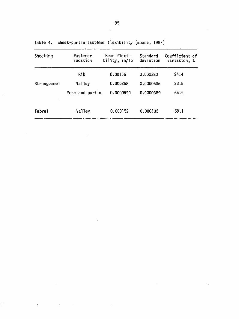
95
Table 4. Sheet-purlin fastener flexibility (Boone, 1987)
Sheeting Fastener Mean flexi- Standard Coefficient of location bility, in/lb deviation variation, %
Strongpanel
Rib
Valley
0.00156
0.000258
0.000380
0.0000606
Seam and purlin 0.0000590 0.0000389
24.4
23.5
65.9
Fabrel Valley 0.000152 0.000105 69,1
96
The diaphragm stiffnesses determined by computer analyses are
shown in Table 5, along with the experimental diaphragm stiffnesses.
The results of the computer analysis will be discussed when the
diaphragms they are modeling are discussed. The test results for
each group of diaphragms with similar construction will be presented
next by sheeting type.
Strongpanel
Control diaphragms 1 and 15
Diaphragms 1 and 15 were constructed the same. There was no
steel removed and the edge purlins were placed at the edge of the
steel. Diaphragm 1 failed at a load of 1400 lb. and diaphragm 15
f a i l e d a t 1 7 0 0 l b . B o t h d i a p h r a g m s f a i l e d b y s p l i t t i n g o f t h e 2 x 8
at corner B. There was no tearing or warping of the sheeting, but
diaphragm 15 did have some compression buckling behind the valley
fastener behind the first fastener at corners A and C at a load of
1600 lbs. (see Figure 46). This is due to the relative displacement
between the sheet and the edge purlin. Also, the stiffness of the
rib fasteners is 640 lb/in., while the stiffness of the valley
fasteners is 3900 lb/in. The rib fasteners do not carry much load,
therefore, the first row of valley fasteners must carry it.
Diaphragm 15 also had cracking starting at corner A and at 1500 lb.,
the top two purlins started to twist along side CD. All twisting and
leaning appeared to leave when the load was released.
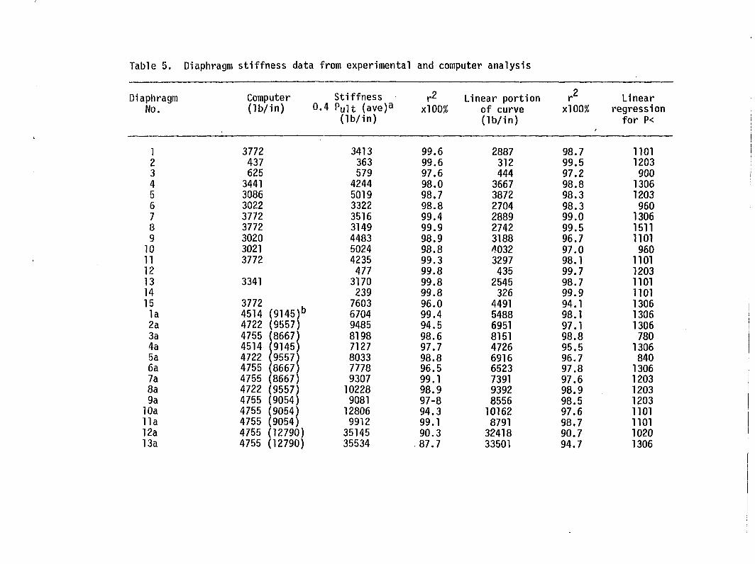
Table 5. Diaphragm stiffness data from experimental and computer analysis
Diaphragm No.
Computer (lb/in)
Stiffness 0.4 Ptilt (ave)a
(lb/in)
r2 xlOO%
Linear portion of curve (lb/in)
r^ xlOO%
Linear regression
for P<
1 3772 3413 99.6 2887 98.7 1101 2 437 363 99.6 312 99.5 1203 3 625 579 97.6 444 97.2 900 4 3441 4244 98.0 3667 98.8 1306 5 3086 5019 98.7 3872 98.3 1203 6 3022 3322 98.8 2704 98.3 960 7 3772 3516 99.4 2889 99.0 1306 8 3772 3149 99.9 2742 99.5 1511 9 3020 4483 98.9 3188 96.7 1101
10 3021 5024 98.8 4032 97.0 960 11 3772 4235 99.3 3297 98.1 1101 12 477 99.8 435 99.7 1203 13 3341 3170 99.8 2545 98.7 1101 14 239 99.8 326 99.9 1101 15 3772 7603 96.0 4491 94.1 1306 la 4514 (9145)° 6704 99.4 5488 98.1 1306 2a 4722 (9557) 9485 94.5 6951 97.1 1306 3a 4755 (8667) 8198 98.6 8151 98.8 780 4a 4514 (9145) 7127 97.7 4726 95.5 1306 5a 4722 (9557) 8033 98.8 6916 96.7 840 6a 4755 (8667) 7778 96.5 6523 97.8 1306 7a 4755 (8667) 9307 99.1 7391 97.6 1203 8a 4722 (9557) 10228 98.9 9392 98.9 1203 9a 4755 (9054) 9081 97-8 8556 98.5 1203
10a 4755 (9054) 12806 94.3 10162 97.6 1101 11a 4755 (9054) 9912 99.1 8791 98.7 1101 12a 4755 (12790) 35145 90.3 32418 90.7 1020 13a 4755 (12790) 35534 87.7 33501 94.7 1306
13a 14a 15al 15a2 15a3 15a4 15a (avg) 16al 16a2 16a (avg)
4755 (12790) 35534 87.7 4541 (9145) 13923 98.9 4541 (9145) 9177 98.4 4541 (9145) 9144 99.3 4541 (9145) 11435 99.1 4541 (9145) 9425 98.0 4541 (9145) 9795 4541 (9145) 8118 99.4 4541 (9145) 8958 99.5 4541 (9145) 8538
33501 9638 8172 9380 9667 8842 9015 7410 8693 8052
94.7 95.9 95.7 99.5 98.1 98.9
99.0 94.7
1306 1306 1203 1203 1203 1203
1101 1101
^Grandnb 3 was analyzed with the mean fastener slip and the mean slip minus one standard deviation.
^0.4 pu 11 (avg) was 600 lb. for Strongpanel and 660 lb. for Grandrib 3.
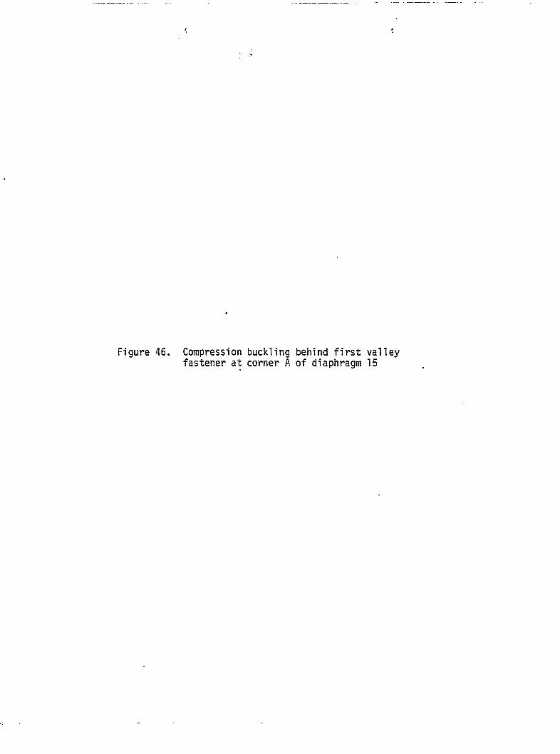
Figure 46. Compression buckling behind first valley fastener at corner A of diaphragm 15
lûû
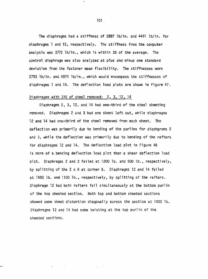
101
The diaphragms had a stiffness of 2887 lb/in. and 4491 lb/in. for
diaphragms 1 and 15, respectively. The stiffness from the computer
analysis was 3772 lb/in., which is within 3% of the average. The
control diaphragm was also analyzed at plus and minus one standard
deviation from the fastener mean flexibility. The stiffnesses were
2793 lb/in. and 4974 lb/in., which would encompass the stiffnesses of
diaphragms 1 and 15. The deflection load plots are shown in Figure 47.
Diaphragms with 33% of steel removed: 2, 3, 12, 14
Diaphragms 2, 3, 12, and 14 had one-third of the steel sheeting
removed. Diaphragms 2 and 3 had one sheet left out, while diaphragms
12 and 14 had one-third of the steel removed from each sheet. The
deflection was primarily due to bending of the purlins for diaphgrams 2
and 3, while the deflection was primarily due to bending of the rafters
for diaphragms 12 and 14. The deflection load plot in Figure 48
is more of a bending deflection load plot than a shear deflection load
plot. Diaphragms 2 and 3 failed at 1200 lb. and 900 lb., respectively,
by splitting of the 2 x 8 at corner B, Diaphragms 12 and 14 failed
at 1500 lb. and 1100 lb., respectively, by splitting of the rafters.
Diaphragm 12 had both rafters fail simultaneously at the bottom purlin
of the top sheeted section. Both top and bottom sheeted sections
showed some sheet distortion diagonally across the section at 1400 lb.
Diaphragms 12 and 14 had some twisting at the top purlin of the
sheeted sections.
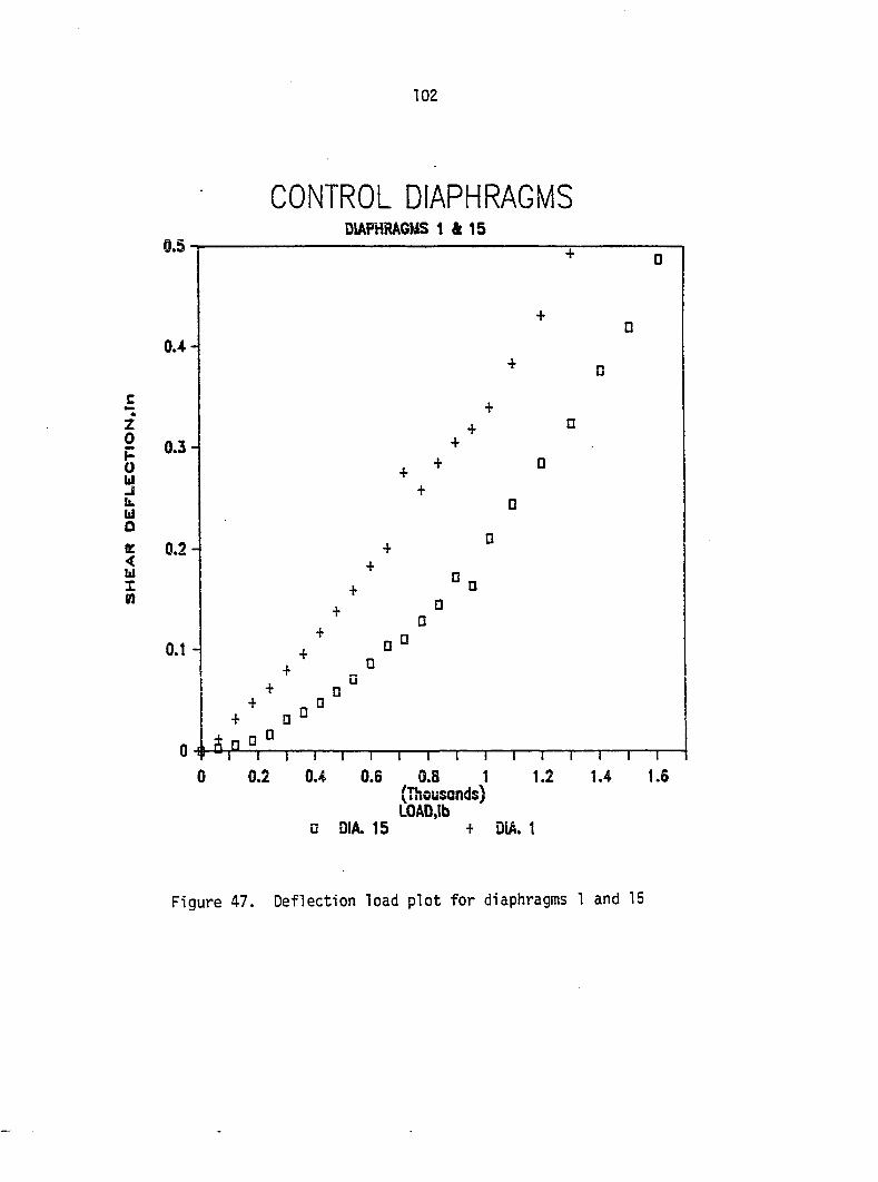
102
CONTROL DIAPHRAGMS DIAPHRAGMS 1 & 15
Z 0 H 0 u J u. hi 0 C < 111
1 M
1 I I I 1 I I I I I I r 0 0.2 0.4 0.6 0.8 1 1.2
(Thousands) LOAD,lb
• DiA. 15 + DiA. 1
Figure 47. Deflection load plot for diaphragms 1 and 15
103
33% OF STEEL REMOVED FROM DIA. 4.5
4-
DIAPHRAGMS 2,3,12.& 14
1 I r
0.6 0.8 1 (Thousands) LOAD.Ib
• DIA. 14 r DIA. 12 » DIA. 3 L DIA. 2
Figure 48. Deflection load plot for diaphragms 2, 3, 12, and 14
104
Diaphragm 3 failed early because of the cupping of the rafter
at corner B. In fact, the grain was running parallel to the minor
bending axis approximately two-thirds of the way from the top of the
rafter. Diaphragm 2 had tears of 3/8 to 1/2 in. at the first row of
fasteners next to the missing sheet. Also, the purlin along edge AD
had the first rib fastener pulled to almost a horizontal position.
The entire rib along the edge of the missing sheet was flattening out
at the fasteners just before failure.
The stiffness of diaphragms 2, 3, 12, and 14 are 312 lb/in.,
444 lb/in., 435 lb/in., and 326 lb/in., respectively. These values
and the deflection load plots indicate that the diaphragm may be
100 lb/in. stiffer if the opening has sheeting on two sides rather
than on one side of it. The tests also show that if one-third of the
sheeting is removed, headers for the purlins or rafters, depending on
the orientation of opening, are needed if the diaphragm is to be
effective. The computer analysis gave a stiffness of 437 lb/in. and
625 lb/in. for diaphragms 2 and 3, respectively. In both cases,
the computer analysis predicted stiffness is about 40% larger than
the experimental. This could be due to the fact that the purlins
are not all fixed to the sheeting on the same plane parallel to the
corrugation. The purlins, in effect, behave like beams hinged at
each sheet-purlin fastener point. Because of the fastening pattern,
the unsupported length of the purlins varies. The analog does not
account for this, nor does it account for a possible change of
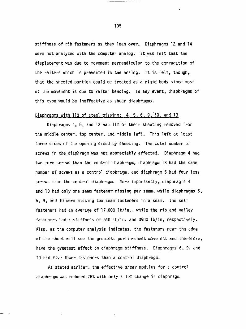
105
stiffness of rib fasteners as they lean over. Diaphragms 12 and 14
were not analyzed with the computer analog. It was felt that the
displacement was due to movement perpendicular to the corrugation of
the rafters which is prevented in the analog. It is felt, though,
that the sheeted portion could be treated as a rigid body since most
of the movement is due to rafter bending. In any event, diaphragms of
this type would be ineffective as shear diaphragms.
Diaphragms with 11% of steel missing: 4, 5, 6, 9, 10, and 13
Diaphragms 4, 5, and 13 had 11% of their sheeting removed from
the middle center, top center, and middle left. This left at least
three sides of the opening sided by sheeting. The total number of
screws in the diaphragm was not appreciably affected. Diaphragm 4 had
two more screws than the control diaphragm, diaphragm 13 had the same
number of screws as a control diaphragm, and diaphragm 5 had four less
screws than the control diaphragm. More importantly, diaphragms 4
and 13 had only one seam fastener missing per seam, while diaphragms 5,
6, 9, and 10 were missing two seam fasteners in a seam. The seam
fasteners had an average of 17,000 lb/in., while the rib and valley
fasteners had a stiffness of 640 lb/in. and 3900 lb/in, respectively.
Also, as the computer analysis indicates, the fasteners near the edge
of the sheet will see the greatest purlin-sheet movement and therefore,
have the greatest affect on diaphragm stiffness. Diaphragms 6, 9, and
10 had five fewer fasteners than a control diaphragm.
As stated earlier, the effective shear modulus for a control
diaphragm was reduced 75% with only a 10% change in diaphragm
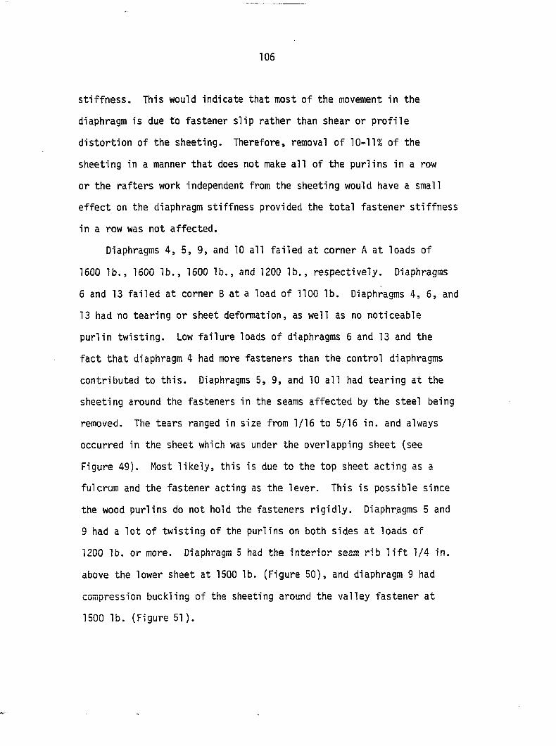
106
stiffness. This would indicate that most of the movement in the
diaphragm is due to fastener slip rather than shear or profile
distortion of the sheeting. Therefore, removal of 10-11% of the
sheeting in a manner that does not make all of the purlins in a row
or the rafters work independent from the sheeting would have a small
effect on the diaphragm stiffness provided the total fastener stiffness
in a row was not affected.
Diaphragms 4, 5, 9, and 10 all failed at corner A at loads of
1600 lb., 1600 lb., 1600 lb., and 1200 lb., respectively. Diaphragms
6 and 13 failed at corner B at a load of 1100 lb. Diaphragms 4, 6, and
13 had no tearing or sheet deformation, as well as no noticeable
purlin twisting. Low failure loads of diaphragms 6 and 13 and the
fact that diaphragm 4 had more fasteners than the control diaphragms
contributed to this. Diaphragms 5, 9, and 10 all had tearing at the
sheeting around the fasteners in the seams affected by the steel being
removed. The tears ranged in size from 1/16 to 5/16 in. and always
occurred in the sheet which was under the overlapping sheet (see
Figure 49). Most likely, this is due to the top sheet acting as a
fulcrum and the fastener acting as the lever. This is possible since
the wood purlins do not hold the fasteners rigidly. Diaphragms 5 and
9 had a lot of twisting of the purlins on both sides at loads of
1200 lb. or more. Diaphragm 5 had the interior seam rib lift 1/4 in.
above the lower sheet at 1500 lb. (Figure 50), and diaphragm 9 had
compression buckling of the sheeting around the valley fastener at
1500 lb. (Figure 51).
Figure 49. Typical sheet tear at rib of Strongpanel sheeting
Figure 50. Seam uplifting at rib of diaphragm 5
Figure 51. Compression buckling behind first valley fastener of diaphragm 9
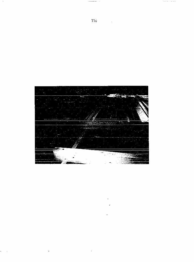
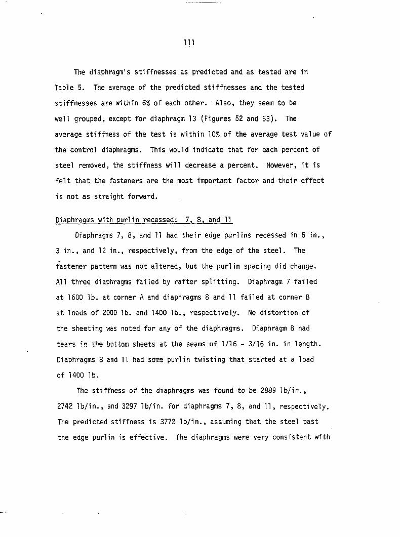
I l l
The diaphragm's stiffnesses as predicted and as tested are in
Table 5. The average of the predicted stiffnesses and the tested
stiffnesses are within 6% of each other. Also, they seem to be
well grouped, except for diaphragm 13 (Figures 52 and 53). The
average stiffness of the test is within 10% of the average test value of
the control diaphragms. This would indicate that for each percent of
steel removed, the stiffness will decrease a percent. However, it is
felt that the fasteners are the most important factor and their effect
is not as straight forward.
Diaphragms with purlin recessed: 7, 8. and 11
Diaphragms 7, 8, and 11 had their edge purlins recessed in 5 in.,
3 in., and 12 in., respectively, from the edge of the steel. The
fastener pattern was not altered, but the purlin spacing did change.
All three diaphragms failed by rafter splitting. Diaphragm 7 failed
at 1600 lb. at corner A and diaphragms 8 and 11 failed at corner B
at loads of 2000 lb. and 1400 lb., respectively. No distortion of
the sheeting was noted for any of the diaphragms. Diaphragm 8 had
tears in the bottom sheets at the seams of 1/16 - 3/16 in. in length.
Diaphragms 8 and 11 had some purlin twisting that started at a load
of 1400 lb.
The stiffness of the diaphragms was found to be 2889 lb/in.,
2742 lb/in., and 3297 lb/in. for diaphragms 7, 8, and 11, respectively.
The predicted stiffness is 3772 lb/in., assuming that the steel past
the edge purlin is effective. The diaphragms were very consistent with
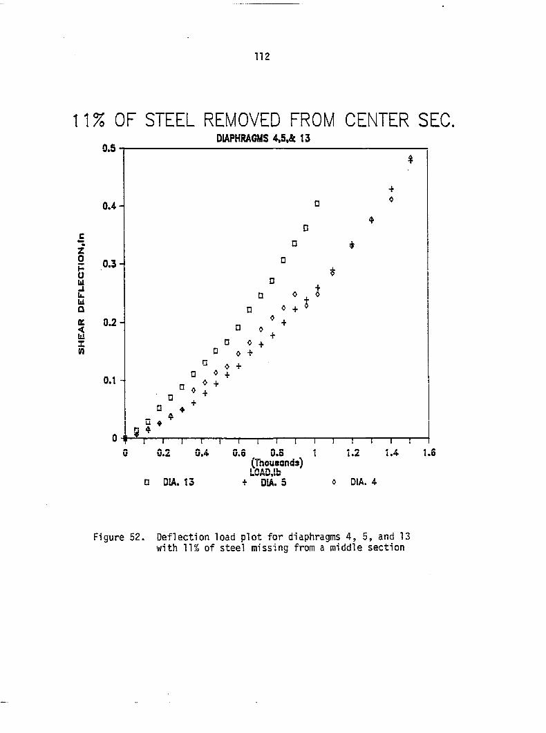
112
11% OF STEEL REMOVED FROM CENTER SEC. DIAPHRAGMS 4,5,& 13
• OtA. 13
0.6 , 0.S 1 (Thousands) LOAD,lb
+ DIA. 5 DIA. 4
Figure 52. Deflection load plot for diaphragms 4, 5, and 13 with 11% of steel missing from a middle section
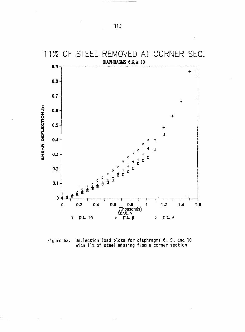
113
11% OF STEEL REMOVED AT CORNER SEC. DIAPHRAGMS 10
z 0 F u 111 _J L. til Q
OC < 111
I n
• D!A. 10
O.S 0.8 (Thousands) LOAD,!b
4- DIA. 8 : DIA, 6
Figure 53. Deflection load plots for diaphragms 6, 9, and 10 with 11% of steel missing from a corner section
114
each other (Figure 54). This was an indication that recessing the
purlins does affect the diaphragm stiffness. However, the stiffest
diaphragm, 11, had the largest recess. Also, as stated earlier, it
is felt that the sheeting is not a major component of movement; reducing
its effectiveness should only have a small impact on stiffness. The
values are within 5% of the diaphragm stiffness predicted when the mean
fastener flexibilities given by Boone (1987) have one standard
deviation added to them. Therefore, the recessing of the purlins in
from the end of the steel has little affect on the diaphragm stiffness.
Grandrib 3
Control diaphragms la, 4a, and 14a
Diaphragms la, 4a, and 14a were made of continuous sheets with the
recommended fastener pattern. Diaphragms 4a and 14a failed at corner
A at loads of 2000 lb. and 1600 lb., respectively. Diaphragm la
failed at 1500 lb. at corner B, Diaphragm la had no tearing of the
sheeting around the fasteners, nor any sheet distortion. Diaphragm 4a
had tears around the fasteners ranging from 1/15 - 1/8 in. at the
fasteners closest to side AB of the diaphragm. Both diaphragms 4a
and 14a had some purlin twisting. It is not apparent if the purlin
twisting caused some small compression buckling around the fasteners
or if it is due to movement between the sheet and purlin (Figure 55).
It does appear that having the fastener very close to the rib helps
control compression buckling. The rib acts as a stiffener. Also,
at low loads such as 480 lb., it appeared that some profile distortion
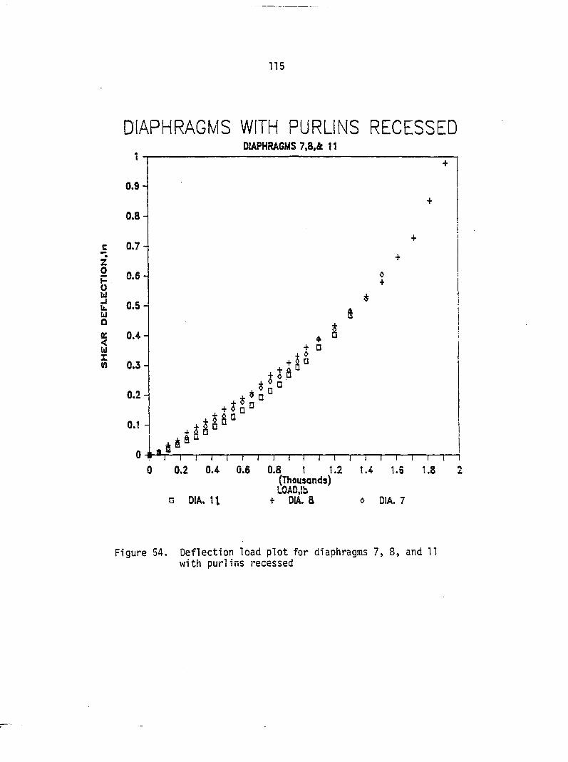
115
DIAPHRAGMS WITH PURLINS RECESSED DIAPHRAGMS 7,a.ft 11
1 1 1 i i ! ! ! 1 I I I r 0 0.2 0.4 0.6 0.8 t 1.2 1.4 1.6
(Thousands)
• DIA. U LOAD,lb
+ DIA. 8 0 DIA. 7
Figure 54. Deflection load plot for diaphragms 7, 8, and 11 with purlins recessed
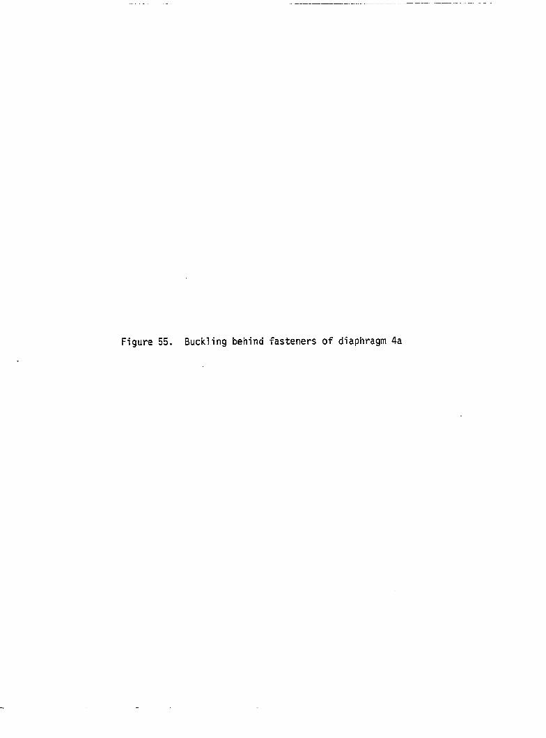
Figure 55. Buckling behind fasteners of diaphragm 4a
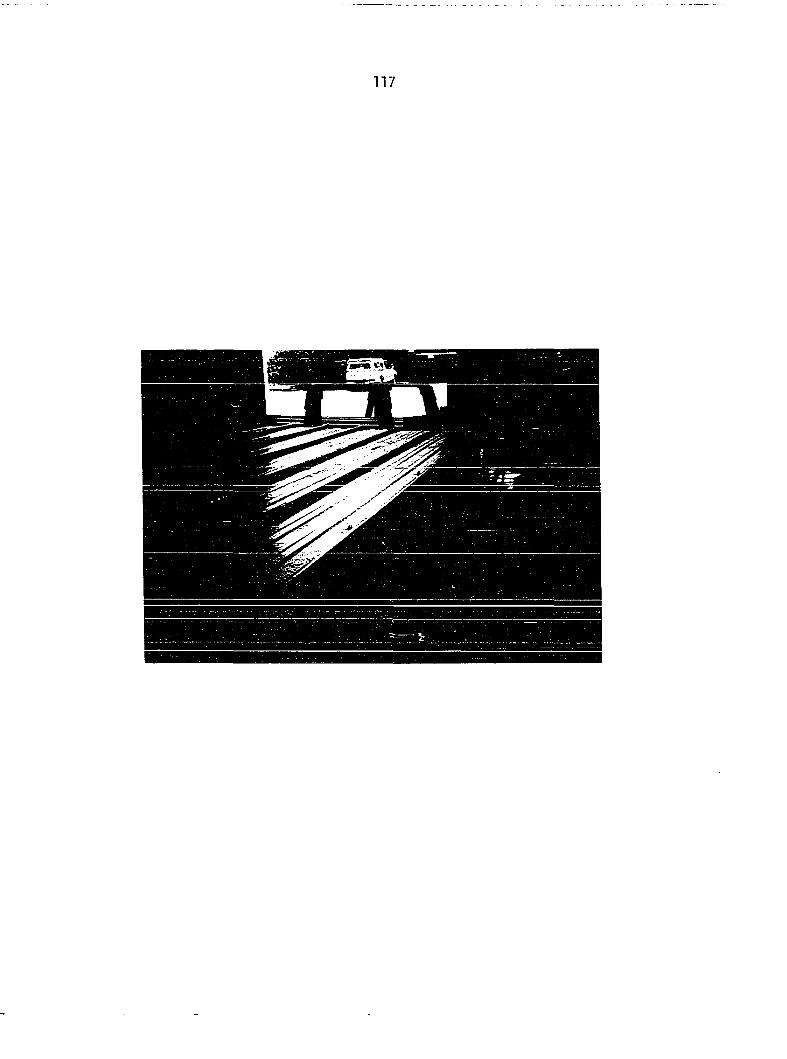
117
118
was occurring. The distortion ran parallel to the corrugation along the
length of the diaphragm in the valley that was next to the rib and was
overlapped by the adjacent sheet. The overlapped rib has a fastener
in the valley next to it only at the two edge purlins. This means
that only two fasteners transfer all the shear or that the intermediate
purlins transfer the shear for about 9 in. between sheets. The computer
analysis shows the two edge fasteners are stressed about three and one-
half times more than the seven fasteners next to the rib on top of the
overlap.
Diaphragms la, 4a, and 14a had tested stiffnesses of 5488 lb/in.,
4726 lb/in., and 9638 lb/in., respectively (see Figure 56). The computer
analysis with the mean fastener flexibility value from Boone (1987)
predicted a diaphragm stiffness of 4514 lb/in. If one standard
deviation is subtracted from the mean, the predicted stiffness is
9145 lb/in. At the sheet overlaps, there is a small lip that extends
under the top sheet approximately 3/16 in. For diaphragm la, 13 out
of 14 fasteners at the lap made some penetration of the bottom sheet
and for diaphragms 4a and 14a, 14 out of 14 penetrated the bottom
sheet. This small lip may have the effect of causing the lap
fasteners to act somewhat like a seam fastener. However, 3/16 in. is
such a small amount that it would seem very unlikely that this effect
could be depended upon, especially if reversed loading was applied.
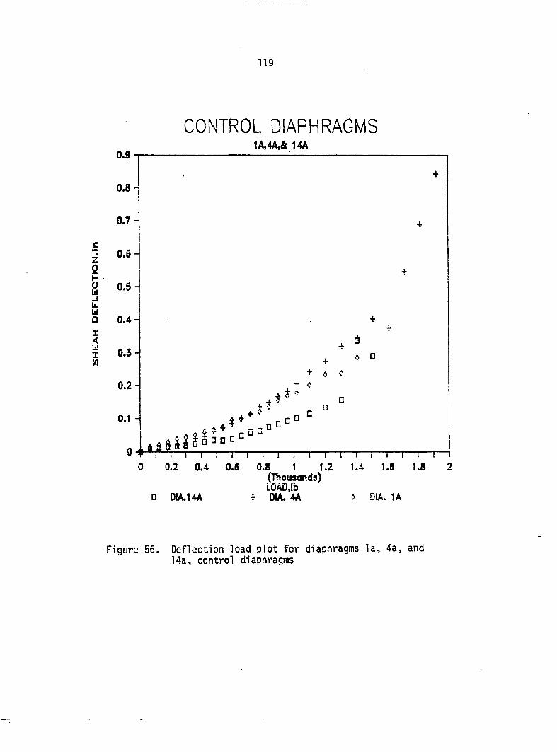
119
CONTROL DIAPHRAGMS 1A,4A,« 14A
1 I i I 1 I I I I I I I I I I r 0 0.2 0.4 0.6 0.8 1 1.2 1.4 1.6 1.8
(Thousands) LOÂD.ib
• DIA.14A DIA. 4A » DIA. 1A
Figure 56. Deflection load plot for diaphragms la, 4a, and 14a, control diaphragms
120
Diaphragms with seams at 6 ft.: 2a, 5a, and 8a
Diaphragms 2a, 5a, and 8a were constructed the same as the control
diaphragms, except two sheets were used in the length of the
diaphragm. The top sheets were 78 in. long and the bottom sheets
were 72 in. long. This allowed for a 6 in. overlap. At the overlap,
the edge purlin fastener pattern was used. This increased the number
of fasteners in a row by one, which tends to increase the stiffness
especially at the side lap between sheets. The use of two sheets in
the diaphragm's length decreases the stiffness by reducing the number
of purlins supporting each sheet and allowing a discontinuity where
the sheets join. Davies and Bryan (1982) proposed the following
equation to account for this discontinuity:
fg = 1 + 0.3n (9)
where f^ = correction factor (see Eq. (6)), and
n = number of sheets in the length of the diaphragm.
All three diaphragms failed at corner B. Diaphragms 2a and 8a
failed at 1800 lb. and diaphragm 5a failed at 1400 lb. Both diaphragms
2a and 8a had some compressive buckling behind the fasteners on sides
AB and CD. Diaphragm 8a had some sheet distortion in each sheet
length along the seam closest to side AB confined to the valley about
35 in. from sides AD and BC. The purlins showed twisting on diaphragms
5a and 8a starting at 1200 lb.
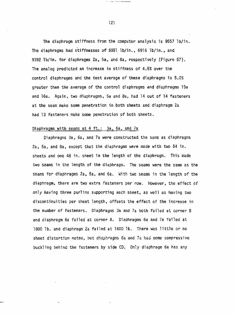
121
The diaphragm stiffness from the computer analysis is 9557 lb/in.
The diaphragms had stiffnesses of 6951 lb/in., 6916 lb/in., and
9392 lb/in. for diaphragms 2a, 5a, and 8a, respectively (Figure 57).
The analog predicted an increase in stiffness of 4.5% over the
control diaphragms and the test average of these diaphragms is 5.0%
greater than the average of the control diaphragms and diaphragms 15a
and 16a. Again, two diaphragms, 5a and 8a, had 14 out of 14 fasteners
at the seam make some penetration in both sheets and diaphragm 2a
had 13 fasteners make some penetration of both sheets.
Diaphragms with seams at 4 ft.: 3a. 6a, and 7a
Diaphragms 3a, 6a, and 7a were constructed the same as diaphragms
2a, 5a, and 8a, except that the diaphragms were made with two 54 in.
sheets and one 48 in. sheet in the length of the diaphragm. This made
two seams in the length of the diaphragm. The seams were the same as the
seams for diaphragms 2a, 5a, and 6a. With two seams in the length of the
diaphragm, there are two extra fasteners per row. However, the effect of
only having three purlins supporting each sheet, as well as having two
discontinuities per sheet length, offsets the effect of the increase in
the number of fasteners. Diaphragms 3a and 7a both failed at corner B
and diaphragm 6a failed at corner A. Diaphragms 6a and 7a failed at
1800 lb. and diaphragm 2a failed at 1600 lb. There was little or no
sheet distortion noted, but diaphragms 6a and 7a had some compressive
buckling behind the fasteners by side CD. Only diaphragm 6a has any
122
0.45
DIAPHRAGMS WITH A SEAM © 6' DIAPHRAGMS 2A,SA,& SA
0,4 -
n t q _
Z 0 H 0 u h. Ill Q K < ki 1 M
0.3-
0.25-
0.2-
0.15-
0.1 -
+ 0 + 0
9 È S
à 5
0
0
0 4 ? I I I I ! 1 1 I I I I I I I 1 I I t 0 0.2 0.4 0.6 0.8 1 . 1.2 1.4 1.6 1.8
(Thousands) LOAD, lb
D DIA. SA -h DiA. SA » DiA. 2A
Figure 57. Load deflection plot for diaphragms 2a, 5a, and 8a with seams at 6 ft.
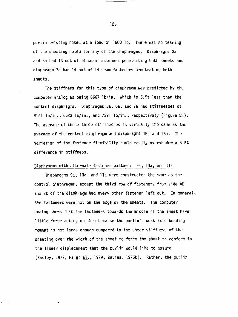
123
purlin twisting noted at a load of 1600 lb. There was no tearing
of the sheeting noted for any of the diaphragms. Diaphragms 3a
and 6a had 13 out of 14 seam fasteners penetrating both sheets and
diaphragm 7a had 14 out of 14 seam fasteners penetrating both
sheets.
The stiffness for this type of diaphragm was predicted by the
computer analog as being 8667 lb/in., which is 5.5% less than the
control diaphragms. Diaphragms 3a, 6a, and 7a had stiffnesses of
8151 lb/in., 6523 lb/in., and 7391 lb/in., respectively (Figure 58).
The average of these three stiffnesses is virtually the same as the
average of the control diaphragm and diaphragms 15a and 16a. The
variation of the fastener flexibility could easily overshadow a 5,5%
difference in stiffness.
Diaphragms with alternate fastener pattern: 9a, 10a, and lia
Diaphragms 9a, 10a, and 11a were constructed the same as the
control diaphragms, except the third row of fasteners from side AD
and BC of the diaphragm had every other fastener left out. In general,
the fasteners were not on the edge of the sheets. The computer
analog shows that the fasteners towards the middle of the sheet have
little force acting on them because the purlin's weak axis bending
moment is not large enough compared to the shear stiffness of the
sheeting over the width of the sheet to force the sheet to conform to
the linear displacement that the purlin would like to assume
(Easley, 1977; Ha et , 1979; Davies, 1976b). Rather, the purlin
124
0.35
DIAPHRAGMS WITH SEAMS @ 4' DIAPHRAGMS 3A.6A,t 7A
1—I—I—r D 0.2 0.4
• DIA. 7A
0.S (Thousands) LOAD.!b DIA. 6A
l.O
: DIA. 3A
Figure 58. Load deflection plot for diaphragms 3a, 6a, and 7a with seams at 4 ft.
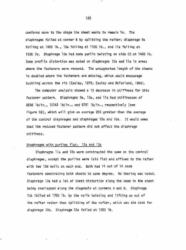
125
conforms more to the shape the sheet wants to remain in. The
diaphragms failed at corner B by splitting the rafter; diaphragm 9a
failing at 1400 lb., 10a failing at 1700 lb., and 11a failing at
1500 lb. Diaphragm 10a had some purlin twisting on side CD at 1400 lb.
Some profile distortion was noted on diaphragms 10a and 11a in areas
where the fasteners were removed. The unsupported length of the sheets
is doubled where the fasteners are missing, which would encourage
buckling across the rib (Easley, 1975; Easley and McFarland, 1969).
The computer analysis showed a 1% decrease in stiffness for this
fastener pattern. Diaphragms 9a, 10a, and 11a had stiffnesses of
8556 lb/in., 10162 lb/in., and 8791 lb/in., respectively (see
Figure 59), which will give an average 25% greater than the average
of the control diaphragms and diaphragms 15a and 15a. It would seem
that the reduced fastener pattern did not affect the diaphragm
stiffness.
Diaphragms with purlins flat: 12a and 13a
Diaphragms 11a and 12a were constructed the same as the control
diaphragms, except the purlins were laid flat and affixed to the rafter
with two lOd nails on each end. Both had 14 out of 14 seam
fasteners penetrating both sheets to some degree. No tearing was noted.
Diaphragm 13a had a lot of sheet distortion along the seam in the sheet
being overlapped along the diagonals at corners A and B. Diaphragm
13a failed at 1700 lb. by the nails twisting and lifting up out of
the rafter rather than splitting of the rafter, which was the case for
diaphragm 12a. Diaphragm 12a failed at 1200 lb.
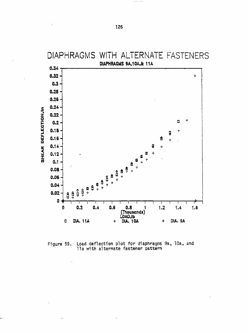
126
DIAPHRAGMS WITH ALTERNATE FASTENERS 8.W
z 0
s u u. U1 Û
IE
5
DIAPHRAGMS 9A.10A,& 11A
Ô ^
1—I—I—!—I—I—I—r 0 0.2 0.4 0.6 0.3 1
(Thousands) LOAD,lb
a DIA. 11A + DIA. IDA « DIA. 9A
Figure 59. Load deflection plot for diaphragms 9a, 10a, and 11a with alternate fastener pattern
127
The computer analog predicted a stiffness of 12,790 lb/in., which
is a 40% increase over the control. The diaphragms had tested
stiffness of 32,418 lb/in. for diaphragm 12a and 33,501 lb/in. for
diaphragm 13a. They both tended to have lower correlation coefficients
which can be seen in Figure 60. The frame for diaphragm 12a was tested
for rolling resistance. It was found to be negligible. The reason
for the high test stiffness values for these two diaphragms is not
immediately apparent.
Diaphragms that were repeat loaded: 15a and 16a
Diaphragms 15a and 16a were constructed the same as the control
diaphragms, but they were repeat loaded because of other testing.
The only thing noted was that some profile distortion occurred around
the failure load on side AB of diaphragm 16a. Diaphragm 15a was loaded
four times and diaphragm 16a was loaded twice. Diaphragm 15a failed
at corner B at a load of 1200 lb. and diaphragm 16a failed at
corner B at a load of 1300 lb. The rafter split in both cases. This
would indicate that repeated loading may decrease the strength of the
rafter-purli n connecti on.
The stiffness of the two diaphragms was quite repeatable
(Figures 61 and 62). Diaphragm 15a had a mean stiffness of 9015 lb/in.
with a coefficient of variation of 7% and diaphragm 16a had a mean
stiffness of 8052 lb/in. and a coefficient of variation of 10%. The
computer analogs predicted stiffness was 9145 lb/in. The repeatability
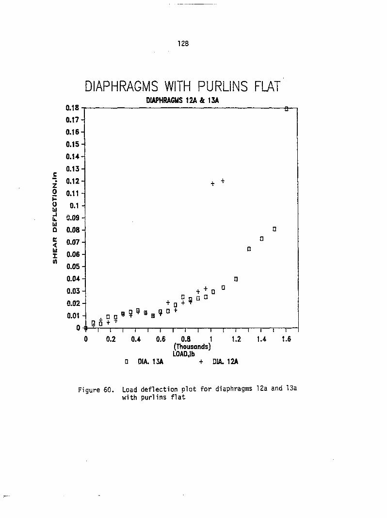
128
DIAPHRAGMS WITH PURLINS FIAT DIAPHRAGMS 12A & ISA
z 0 p u tli J u. w Q
K < lU 1 M
1 I I I I I I I r 0.4 0.6 0.8 1 1.2
(Thousands) LOADJb
• DIA. 13A + DIA. 12A
Figure 60. Load deflection plot for diaphragms 12a and 13a with purlins flat
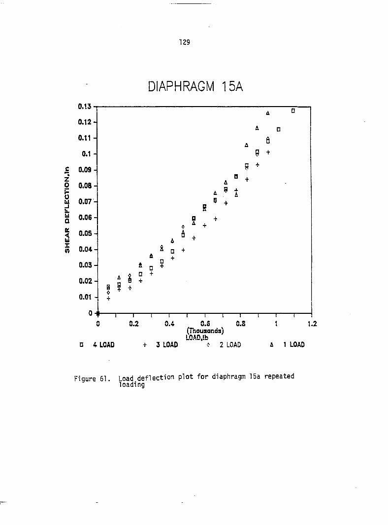
129
DIAPHRAGM ISA
Z O
0 y
b Q ft
g
5
» S
I 0.4 0.6 0.8
(Thousands) man IK
0 4 LOAD 3 LOAD 2 LOAD A 1 LOAD
Figure 61. Load deflection plot for diaphragm 15a repeated loading

130
DIAPHRAGM 16A 0.17
0.16
0.15
0.U
0.13
c 0.12
Z 0.11 o P 0.1 o W 0.09
u 0.08 Q K 0.07
u 0.06 X w 0.05
0.04
0.03
0.02 O=0t
0
0 0.2 0.4 Q.6 0.8 1 1.2 1.4 (Thousands) LOAD,lb
n SECOND LOADING r FIRST LOADING
Figure 62. Load deflection plot of diaphragm 16a repeated loading
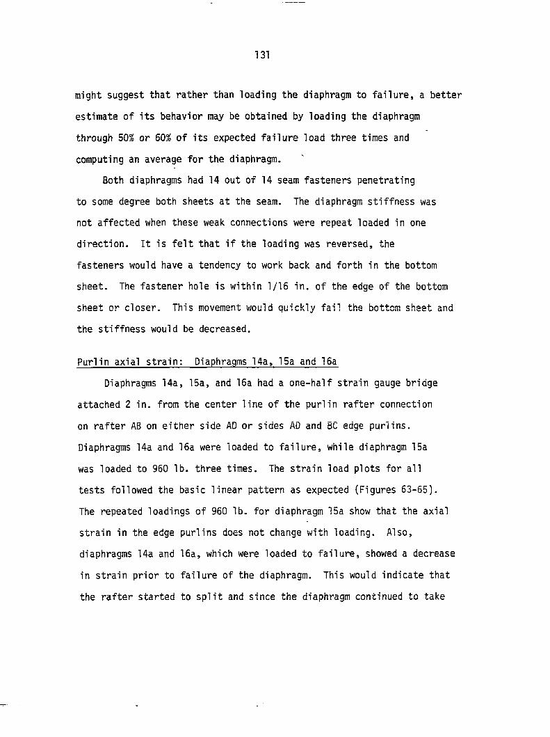
131
might suggest that rather than loading the diaphragm to failure, a better
estimate of its behavior may be obtained by loading the diaphragm
through 50% or 60% of its expected failure load three times and
computing an average for the diaphragm.
Both diaphragms had 14 out of 14 seam fasteners penetrating
to some degree both sheets at the seam. The diaphragm stiffness was
not affected when these weak connections were repeat loaded in one
direction. It is felt that if the loading was reversed, the
fasteners would have a tendency to work back and forth in the bottom
sheet. The fastener hole is within 1/15 in. of the edge of the bottom
sheet or closer. This movement would quickly fail the bottom sheet and
the stiffness would be decreased.
Purlin axial strain: Diaphragms 14a, 15a and 15a
Diaphragms 14a, 15a, and 15a had a one-half strain gauge bridge
attached 2 in. from the center line of the purlin rafter connection
on rafter AB on either side AD or sides AD and BC edge purlins.
Diaphragms 14a and 15a were loaded to failure, while diaphragm 15a
was loaded to 950 lb. three times. The strain load plots for all
tests followed the basic linear pattern as expected (Figures 63-55).
The repeated loadings of 960 lb. for diaphragm 15a show that the axial
strain in the edge purlins does not change with loading. Also,
diaphragms 14a and 16a, which were loaded to failure, showed a decrease
in strain prior to failure of the diaphragm. This would indicate that
the rafter started to split and since the diaphragm continued to take
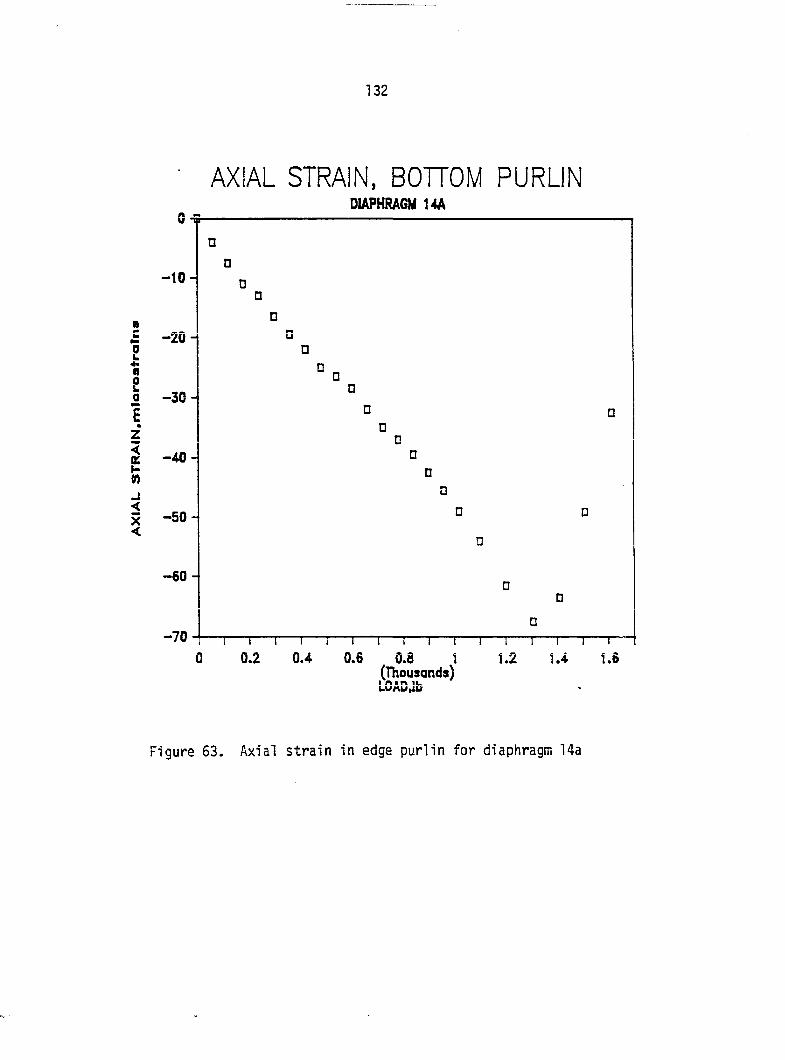
132
AXIAL STRAIN. BOTTOM PURLIN 0-5
DIAPHRAGM 14A
Î n 2 0
z i M J < X <
1 I r
0.6 0.8 1 (Thousands) LCAwtlb
Figure 63. Axial strain in edge purlin for diaphragm 14a
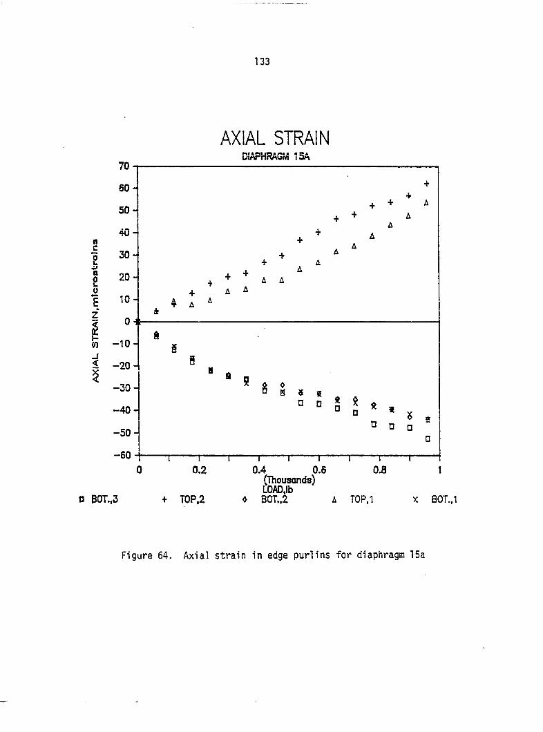
133
«I c
1 a 2 u
(0
<
<
AXIAL STRAIN DIAPHRAGM ISA
-50-
0 BOT.,3 T0P,2
(Thousonds) LOAD,lb BOT.,2 TOP.l
Figure 64. Axial strain in edge purlins for diaphragm 15a
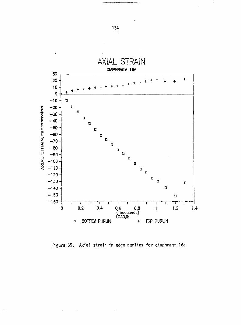
134
AXIAL STRAIN DIAPHRAGM 16A
30-1
20- + + + + + + + ^
10- + + + + + + + + + ' + ^
V 1
-10- •
n —20 - n c 0 -30-
0
n -40-•
0 D
1 o
in 1
JO|
D
1 o
to 1
[LU
'
n
Z -70 • < 0 K -80- N
1 o
OJ
1
s D
_r N < -100-
n
< -110- •
-120-D
• -130- ° •
-140 - 0
-150- n
-160- i ! ! 1 ! 1 1 1 I 1 1 I 1
0 0.2 0.4 0.6 0.8 1 1.2 1.4 (Thousands) LOAD,lb
0 BOTTOM PURUN + TOP PURUN
Figure 65. Axial strain in edge purlins for diaphragm 16a
135
load, part of the axial force in the purlin must have distributed itself
to the next intermediate purlin. Because the failure mechanism of the
diaphragm is not well understood, it would be difficult to establish the
axial force in the 2x8 that caused the splitting of the 2x8 from the
applied load. The actual failure of the diaphragm may be more of a
function of the displacement of the purlin perpendicular to the
splitting 2x8 rather than load.
The nonlinear behavior of diaphragms 14a and 16a, shown in their
respective load deflection plots (Figures 56 and 52), occurs at the
same load the axial strain in the purlins begins to decrease
(Figures 63 and 65). The nonlinear behavior of the test diaphragms
would appear to be a function of the type of failure that occurred at
the purlin-rafter connection. If the failure was brittle, then there
is little change in the deflection load plot. However, if the failure
is slow with substantial splitting, then a change in the deflection
load curve would be seen.
The slope for the strain load plots for diaphragms 14a, 15a (top),
and 15a (bottom) are 0.0425, 0.0432, and 0.0585, respectively, which
has an average of 0.0501. For a modulus of elasticity of
1.8 X 10® Ib/in^ and a cross-sectional area of 5.25 in^, the force in
the edge purlin would be 0.473 lb. per pound of load. A diaphragm
96 in. X 144 in. with supports recessed in 6 in. from the end of the
diaphragm was analyzed using a finite element package, "Images", on a
Zenith 150 with an 8087 processing chip. The analysis predicted an
axial force in the edge purlin of 1009 lb. at a load of 2000 lb. This
136
yields an axial force in the purlin of 0.505 lb. per pound load.
Diaphragm 16a was not included in this average because it is apparent
from Figure 65 that it was not behaving the same as diaphragms 14a and
15a.
The top purlin, side BC of diaphragm 16a, is hardly being
strained, while the bottom purlin shows substantial strain. The slope of
the strain load curves are 0.0159 and 0.124, respectively. The 2 x 8 at
the top purlin or maybe the purlin-rafter connection appears not to be
very stiff. This would allow corner B to move parallel to the purlin
without a large axial purlin force. The bottom purlin would be forced
to take most of the load. The top purlin-rafter connection failed
suddenly at corner B, so there isn't any decrease of strain seen prior
to failure.
Strain gauge rosettes: Diaphragms 15a and 16a
Strain gauge rosettes were mounted on diaphragms 15a and 16a
(Figures 19 and 20). The rosette by corner B will be referred to as
top left, by corner C as top right, the one near the center of the
diaphragm and close to side BC as top middle, and the one centered on
the diaphragm as middle center. The readings for diaphragm 15a were
taken until failure, while diaphragm 16a was loaded to 960 lb.
The strain perpendicular to the corrugations, e , does not
follow a particular pattern (Figures 66 and 67). The top left
corner has a positive strain, tension, for diaphragm 15a and a
negative strain, compression, for diaphragm 15a. The top middle and
the middle center strains are small, but tend to be negative. The
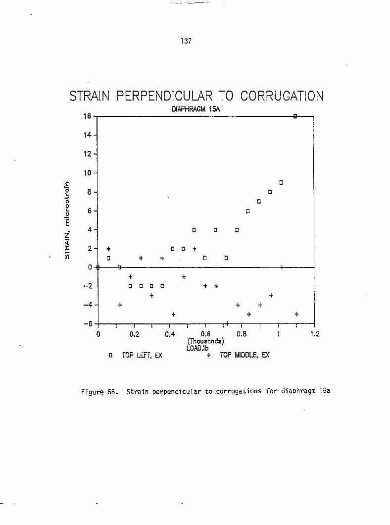
137
STRAIN PERPENDICUL7\R TO CORRUGATION DIAPHRAGM ISA
0 0 +
1 1 1 n—1 ! r 0.4 _ 0.6 ^ 0.8 1
(Thousands) LOAD.Ib
n TOP LEFT, EX + TOP MIDDLE. EX
Figure 66. Strain perpendicular to corrugations for diaphragm 15a
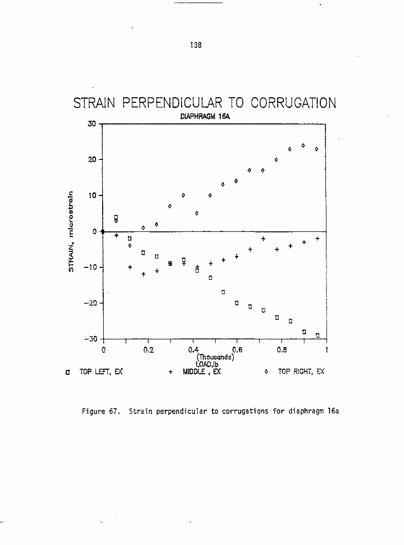
138
STRAIN PERPENDICULAR TO CORRUGATION DIAPHRAGM 16A
0.4 0.6 (Thousands) LOAD,lb
0 TOP LEFT. DC + MIDDLE . EX » TOP RIGHT, EX
Figure 67. Strain perpendicular to corrugations for diaphragm 16a
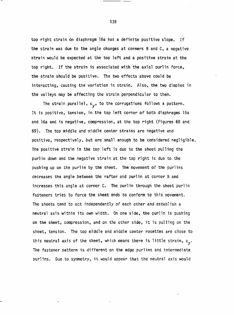
139
top right strain on diaphragm 16a has a definite positive slope. If
the strain was due to the angle changes at corners B and C, a negative
strain would be expected at the top left and a positive strain at the
top right. If the strain is associated with the axial purlin force,
the strain should be positive. The two effects above could be
interacting, causing the variation in strain. Also, the two dimples in
the valleys may be affecting the strain perpendicular to them.
The strain parallel, to the corrugations follows a pattern.
It is positive, tension, in the top left corner of both diaphragms 15a
and 16a and is negative, compression, at the top right (Figures 68 and
69). The top middle and middle center strains are negative and
positive, respectively, but are small enough to be considered negligible.
The positive strain in the top left is due to the sheet pulling the
purlin down and the negative strain at the top right is due to the
pushing up on the purlin by the sheet. The movement of the purlins
decreases the angle between the rafter and purlin at corner B and
increases this angle at corner C. The purlin through the sheet purlin
fasteners tries to force the sheet ends to conform to this movement.
The sheets tend to act independently of each other and establish a
neutral axis within its own width. On one side, the purlin is pushing
on the sheet, compression, and on the other side, it is pulling on the
sheet, tension. The top middle and middle center rosettes are close to
this neutral axis of the sheet, which means there is little strain,
The fastener pattern is different on the edge purlins and intermediate
purlins. Due to symmetry, it would appear that the neutral axis would
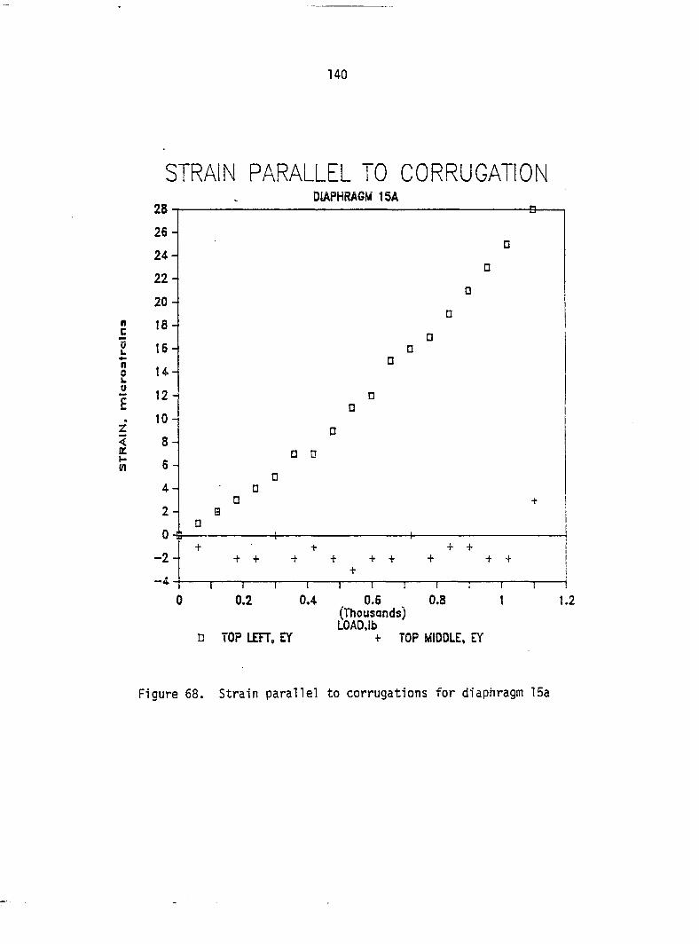
140
STRAIN PARALLEL TO CORRUGATION DIAPHRAGM ISA
• 0
1 1 ! 1 1 1 r 0.4 0.6 0.8 1
(Thousands) LOAD.lb
n TOP LEFT, EY + TOP MIDDLE, EY
Figure 68. Strain parallel to corrugations for diaphragm 15a
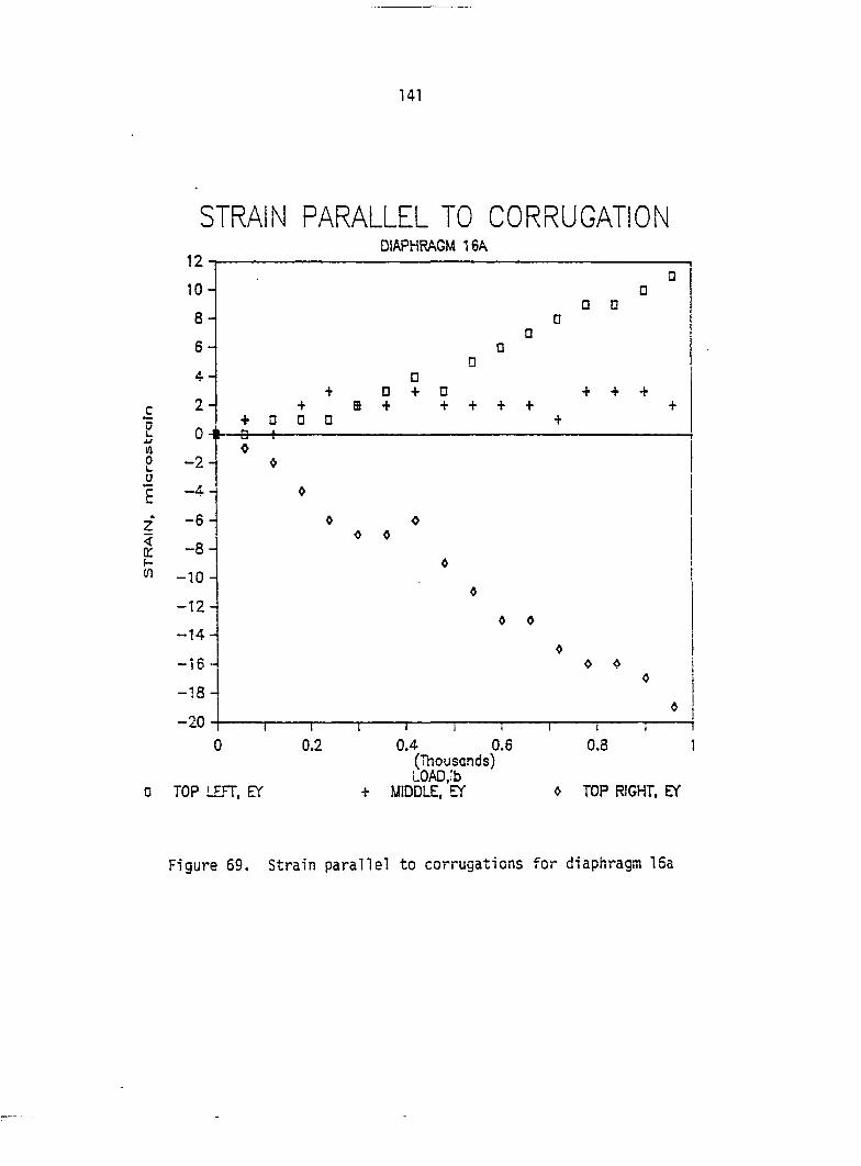
141
Z <
!f)
STRAIN PARALLEL TO CORRUGATION DIAPHRAGM ISA
10
8 -
6 -
4-
2 -
0 H
—2 -
-4 -
— 6 -
—8 -
-10 -
- 1 2 -
-14-
-10-
-18-
-20
D n
n 0 + 0 + + + + +
+ + +
+ 0 0 0 -5 1
» c 0 «
0 0
« Ô
0 TOP LEFT. EY
0.2 0.4 0.6 (Thousands) LOAD,lb
+ MIDDLE, n
1 1 1
0.8
0 TOP RIGHT, ET
Figure 69. Strain parallel to corrugations for diaphragm 15a
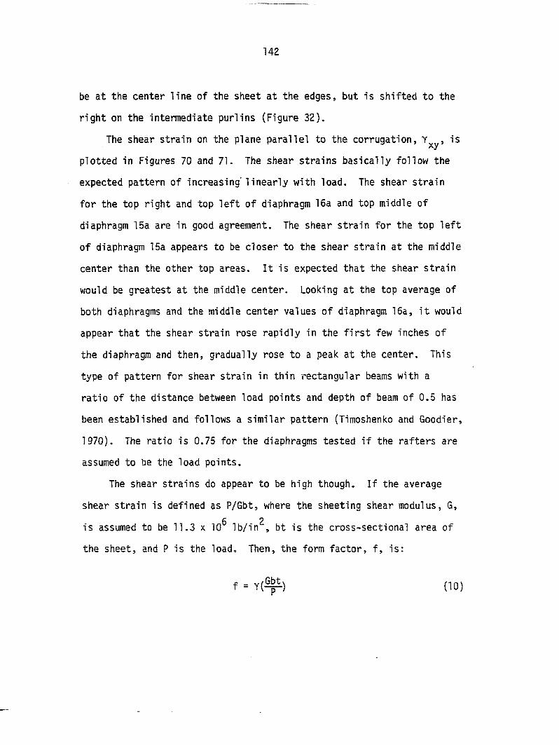
142
be at the center line of the sheet at the edges, but is shifted to the
right on the intermediate purlins (Figure 32).
The shear strain on the plane parallel to the corrugation, is
plotted in Figures 70 and 71. The shear strains basically follow the
expected pattern of increasing" linearly with load. The shear strain
for the top right and top left of diaphragm 16a and top middle of
diaphragm 15a are in good agreement. The shear strain for the top left
of diaphragm 15a appears to be closer to the shear strain at the middle
center than the other top areas. It is expected that the shear strain
would be greatest at the middle center. Looking at the top average of
both diaphragms and the middle center values of diaphragm 16a, it would
appear that the shear strain rose rapidly in the first few inches of
the diaphragm and then, gradually rose to a peak at the center. This
type of pattern for shear strain in thin rectangular beams with a
ratio of the distance between load points and depth of beam of 0.5 has
been established and follows a similar pattern (Timoshenko and Goodier,
1970). The ratio is 0.75 for the diaphragms tested if the rafters are
assumed to be the load points.
The shear strains do appear to be high though. If the average
shear strain is defined as P/Gbt, where the sheeting shear modulus, G,
is assumed to be 11.3 x 10 lb/in , bt is the cross-sectional area of
the sheet, and P is the load. Then, the form factor, f, is;
f = Y(^) (10)
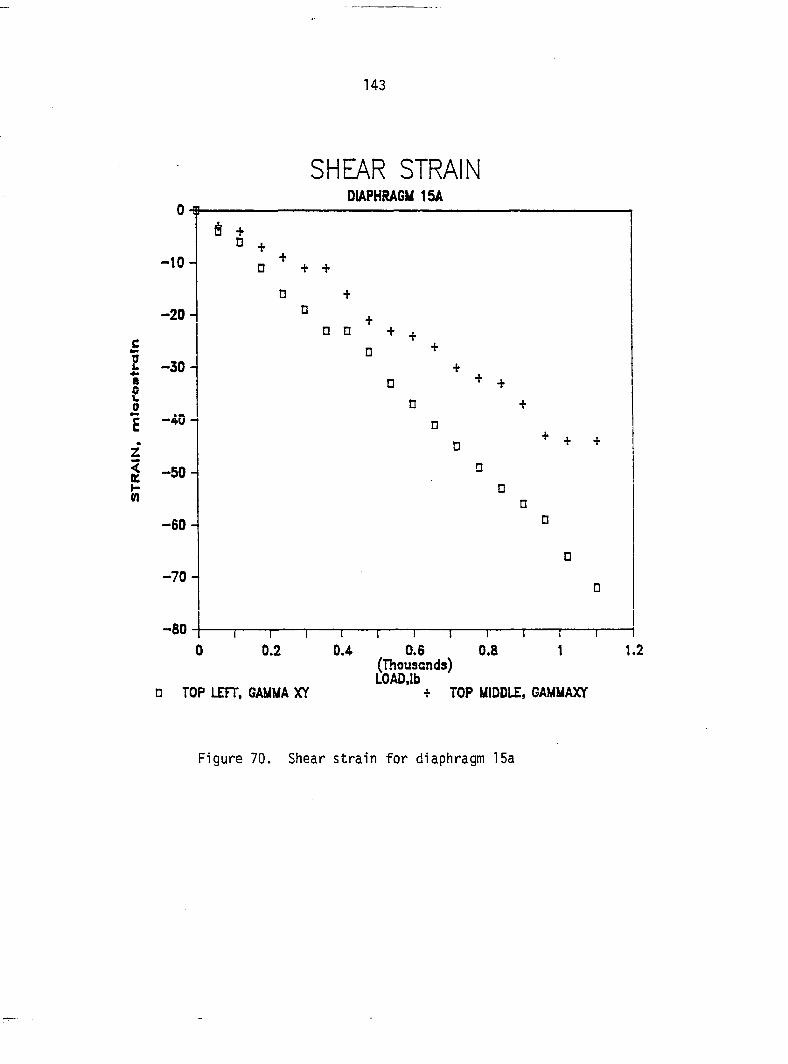
143
0 •»
SHEAR STRAIN DIAPHRAGM ISA
—10 -
-20-
: -30 • £ 0
Î n
—40 -
—50 -
—60 -
-70 -
-80
È
0 + +
n
+
D
n n + ^
+ +
1 r 1 r 0.2 1
0 TOP LEFT, GAMMA XY
1 I r 0.4 0.5 0.8
(Thousands) LGAD.lb
+ TOP MIDDLE, GAMMAXr
1.2
Figure 70. Shear strain for diaphragm 15a
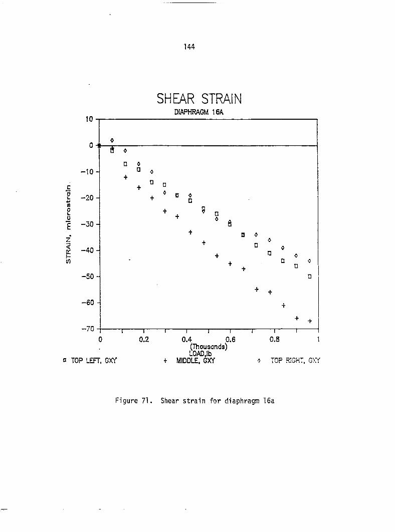
144
SHEAR STRAIN DIAPHRAGM 16A
v —40 -
0 TOP LEFT. GXY
I I r
0.4 0.6 (Thousands) LOAD.lb
+ MIDDLE. GXY -> TOP RIGHT.
Figure 71. Shear strain for diaphragm 16a
145
where Y is test shear strain, in/in. The form factor thus calculated
has an average value of 1.16 for the top of diaphragms 15a and 16a, and
an average value of 1.65 for the middle center of diaphragm 16a. It
does appear, though, that the form factor is tending towards 1.1 for
the top of the diaphragms and 1.5 for the middle center (Table 6). The
higher value could be due to the forces being applied to the sheeting
through the fasteners which are causing the strains parallel and
perpendicular to the corrugations. The shear strains are small, which
tends to support the earlier assumption that for this type of diaphragm
system, the sheet shear deflection is less than 10% of the total
diaphragm deflection.
Brittle coat test: Diaphragm 15a
Diaphragm 15a had Tens-Loc brittle coating applied to the first
24 in. of the diaphragm starting at side BC. The brittle coating did
not appear to work well. There are several reasons for this:
1. The area covered was too large for one person to watch and
load the diaphragm at the same time.
2. Too many load points (the same loading as in the testing for
deflection) were used and they were too close together.
3. The largest tensile principle strain recorded at any rosette
was approximately 50 microstrains. The test bars indicated
that the brittle coat would crack at a strain of 150-200
microstrains.
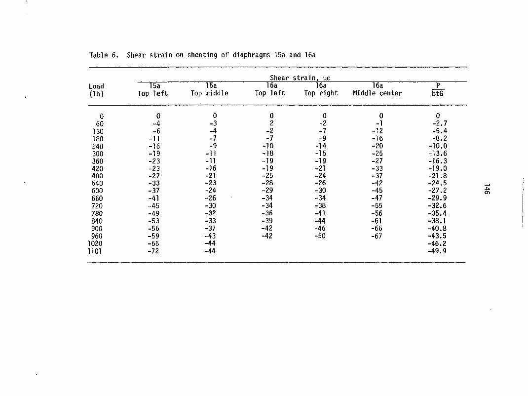
Tab!
Load (lb)
0 60
130 180 240 300 360 420 480 540 600 660 720 780 840 900 960
1020 1101
Shear strain on sheeting oi' diaphragms 15a and 16a
Shear strain, pe T5a~ 15a 16a 16a 16a J_
Top left Top middle Top left Top right Middle center btG
0 0 0 0 0 0 -4 -3 2 -2 -1 -2.7 -6 -4 -2 -7 -12 -5.4
-11 -7 -7 -9 -16 -8.2 -16 -9 -10 -14 -20 -10.0 -19 -11 -18 -15 -25 -13.6 -23 -11 -19 -19 -27 -16.3 -23 -16 -19 -21 -33 -19.0 -27 -21 -25 -24 -37 -21.8 -33 -23 -28 -26 -42 -24.5 -37 -24 -29 -30 -45 -27.2 -41 -26 -34 -34 -47 -29.9 -45 -30 -34 -38 -55 -32.6 -49 -32 -36 -41 -56 -35.4 -53 -33 -39 -44 -61 -38.1 -56 -37 -42 -46 -66 -40.8 -59 -43 -42 -50 -67 -43.5 -66 -44 -46.2 -72 -44 -49.9
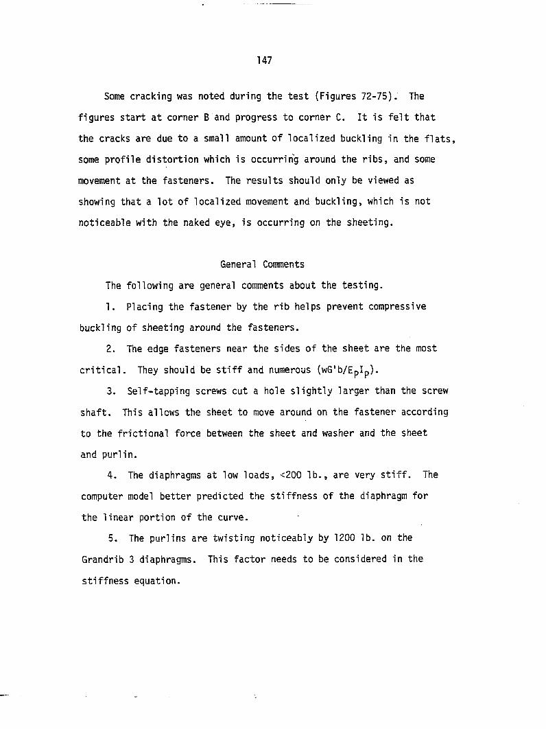
147
Some cracking was noted during the test (Figures 72-75). The
figures start at corner B and progress to corner C. It is felt that
the cracks are due to a small amount of localized buckling in the flats,
some profile distortion which is occurring around the ribs, and some
movement at the fasteners. The results should only be viewed as
showing that a lot of localized movement and buckling, which is not
noticeable with the naked eye, is occurring on the sheeting.
General Comments
The following are general comments about the testing.
1. Placing the fastener by the rib helps prevent compressive
buckling of sheeting around the fasteners.
2. The edge fasteners near the sides of the sheet are the most
critical. They should be stiff and numerous (wG'b/EpIp).
3. Self-tapping screws cut a hole slightly larger than the screw
shaft. This allows the sheet to move around on the fastener according
to the frictional force between the sheet and washer and the sheet
and purlin.
4. The diaphragms at low loads, <200 lb., are very stiff. The
computer model better predicted the stiffness of the diaphragm for
the linear portion of the curve.
5. The purlins are twisting noticeably by 1200 lb. on the
Grandrib 3 diaphragms. This factor needs to be considered in the
stiffness equation.
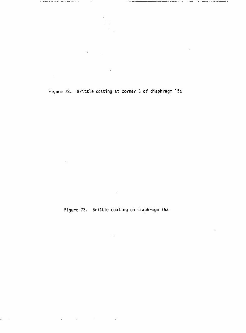
Figure 72. Brittle coating at corner B of diaphragm 15a
Figure 73. Brittle coating on diaphragm 15a
Figure 74. Brittle coating on diaphragm 15a
Figure 75. Brittle coating at corner C on diaphragm
Ibl
152
6. The Grandrib 3 diaphragm deflection load plots are more curved
than the Strongpanel plots. The two edge fasteners near the seams
leave most of the edge rib free to distort.
7. The diaphragms will shift load from the failing purlin-rafter
connection and continue to take load. The failure mechanism needs to
be investigated.
8. The sheeting profile distortion constant, K^, for this type of
sheeting can be taken as being between 0.01 and 0.02. The profiles have
large flat areas with small ribs compared to the profiles used in steel
framed buildings. This means that the shear center is closer to the
center line of the sheet and there is less of a tendency for the sheet
to distort. Also, fasteners placed in the rib or at the rib edge will
help control profile distortion.
153
PROPOSED PREDICTIVE MODELS
Diaphragm-Frame Interaction
To apply diaphragm action to buildings, the diaphragm-frame
interaction must be modeled. The interaction has been modeled by a force
distribution technique (Bryan and El-Dakhakhni, 1964; Hoagland, 1981),
by treating the diaphragm as a deep beam (Luttrell, 1965), or by
treating the diaphragm as springs connecting the frames together in a
plane truss/frame computer analysis (Bryan and Davies, 1975). All three
methods of modeling the diaphragm-frame interaction have advantages.
Treating the diaphragm as a deep beam or the force distribution method
is a familiar concept to designers. However, these two methods become
cumbersome if such things as nonrigid end walls are introduced into the
analysis. The most appropriate method for modeling the diaphragm-frame
interactions appears to be modeling the diaphragm as springs connecting
the frame together. Microcomputers and plane frame/truss analysis
packages are becoming less expensive all the time. Also, it is
easier for the user to incorporate the effects of nonrigid end walls,
or nonsymmetric frames or diaphragms into the analysis.
Bryan and Davies (1975) first proposed the concept. Their model
used one spring to connect one eave of a frame to the ridge of another
frame (Figure 5). This meant that each diaphragm was modeled by one
spring which is quite satisfactory for plane arched frames. Frames
made of wood usually have some sort of truss system attached to posts
which makes it necessary to use more than one spring to model each
154
diaphragm (Figure 76). The spring elements representing the diaphragm
have a moment of inertia of 0.0 and their cross-sectional area is given
by:
A = § (11)
2 where A = cross-sectional area of analog spring member, in ,
K = stiffness of diaphragm being modeled, lb/in.,
L = length of analog member, in., and
2 E = modulus of elasticity of analog member, lb/in .
In the plane frame/truss model, the.frames occupy the same plane. The
length of the analog member, L, is equal to the eave to ridge distance.
The frames are shown apart in Figure 76 to make it easier to view the
connections.
The frame shown in Figure 76 was analyzed using Bryan and Davies
method and two springs representing each diaphragm. The end walls were
restrained at the eaves. Table 7 shows that Bryan and Davies method
predicts little force in the top chord of the end frame members un the
right side. The spring representing the diaphragm that connects the
end frame to the middle frame is connected to the ridge of the end frame.
All of the force in the diaphragm was delivered to the end frame
ridge. The force then was carried to the top chord on the left side
to the eave restraint on the left side. The deflections for the eaves
and ridge of the middle frame are given in Table 8. There was little
difference in the deflections.
155
500 lb.
n-rj Frame 3 1000 lb.
rm Frame 2
Frame 1 rm rfTT
Figure 76. Diaphragm-frame interaction analog
156
Table 7. Top chord axial forces
Top chord axial forces, lb. Middle frame End frame Left to right Left to right
Bryan and Davies (1975) 322 308 209 205 303 307 1.14 1.79
2 spring system 309 295 197 193 161 162 110 109
Table 8. Deflections of middle frame
Deflection, in.
Eave Middle frame
Ri dge Eave
Bryan and Davies (1975) 0.0442 0.0300 0.0302
2 spring system 0.0424 0.0286 0.0285
Table 9. Deflections of middle frame, portal frame
Deflection, in. Middle frame
Left eave Right eave Average
Force distribution
Bryan and Davies (1975)
2 springs
0.0590
0.0625
0.0625
0.0590
0.0550
0.0550
0.0590
0.0588
0.0588
157
The frame shown in Figure 76 was also analyzed with four springs
representing the diaphragms. The springs were of one-half the length
used for the two-spring analysis and they connected to the frames at
the eaves, ridges, and midpoints of the top chords. The force in the
top chord of the middle truss had an increase in axial force of the
lower left member. The increase was about 15%, which is much smaller
than the 90% differences when the two-spring method is compared to
Bryan and Davies' method. The diaphragm-frame interaction is better
modeled when the number of spring elements representing the diaphragm
increases. However, the more springs used means more members and
possibly more nodes which tend to complicate the problem. It is felt
that for most frames, two springs would be sufficient. If the truss
system is unsymmetric or restrained in an unusual manner, more
springs may be necessary.
A portal frame, as shown in Figure 77, was also analyzed using
Bryan and Davies' method, two springs, and the force distribution
method. The deflections for Bryan and Davies method and the two-spring
method are identical (Table 9). However, the force distribution method
yields a deflection that is 5% less for the loaded eave and 8% greater
for the eave that was not loaded than the two-spring method. The force
distribution method does not account for the rotation of the eave
joints or any axial extension or compression of the frame members. For
simple frames, the methods yield the same average results.
Often, end frames in post framed buildings are not rigid. They
are usually sheeted with the same sheeting as the roof and often
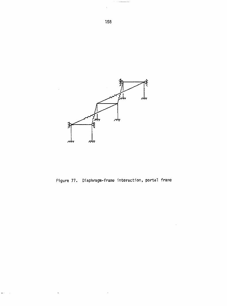
158
rm
Figure 77. Diaphragm-frame interaction, portal frame
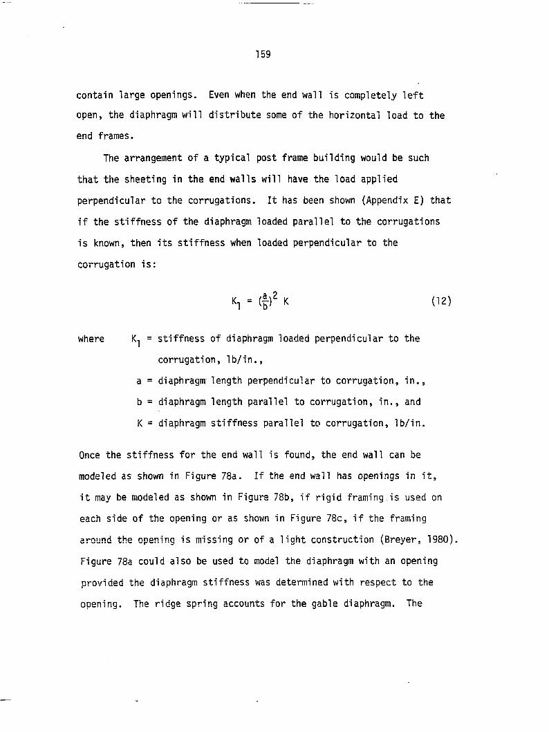
159
contain large openings. Even when the end wall is completely left
open, the diaphragm will distribute some of the horizontal load to the
end frames.
The arrangement of a typical post frame building would be such
that the sheeting in the end walls will have the load applied
perpendicular to the corrugations. It has been shown (Appendix E) that
if the stiffness of the diaphragm loaded parallel to the corrugations
is known, then its stiffness when loaded perpendicular to the
corrugation is:
= (|)^ K (12)
where K-j = stiffness of diaphragm loaded perpendicular to the
corrugation, lb/in.,
a = diaphragm length perpendicular to corrugation, in.,
b = diaphragm length parallel to corrugation, in., and
K = diaphragm stiffness parallel to corrugation, lb/in.
Once the stiffness for the end wall is found, the end wall can be
modeled as shown in Figure 78a. If the end wall has openings in it,
it may be modeled as shown in Figure 78b, if rigid framing is used on
each side of the opening or as shown in Figure 78c, if the framing
around the opening is missing or of a light construction (Breyer, 1980).
Figure 78a could also be used to model the diaphragm with an opening
provided the diaphragm stiffness was determined with respect to the
opening. The ridge spring accounts for the gable diaphragm. The
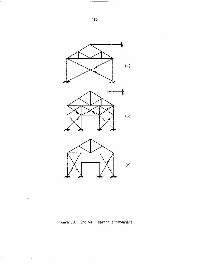
Figure 78. End wall spring arrangement
161
gable diaphragm may not.have any stiffness if a false rafter is used
for its attachment.
The diaphragm-frame system shown in Figure 78 was analyzed two
more times. Once with the end wall open and once with a tension brace
placed diagonally from the top of one column to the bottom of the other.
The eave and ridge deflections are given in Table 10. The bracing
allows three and one-half times more movement than the restrained eaves
case. Also, the open end wall reduced the middle frame deflection by
two-thirds, while the end frames deflection increased by four-thirds.
The open end wall case had the deflection virtually the same for the
middle and end frames. The deflection is equal to the total load
divided by three times the stiffness of the bare frame:
(500 + 1000 + 500/3(525)) = 1.27 in.
In the event that either the software or hardware are not available
for computer analysis, one can use the force distribution procedure as
shown in Figure 5 or the deep beam procedure shown in Figure 7. For
the deep beam procedure, an effective shear modulus, G", for the
complete diaphragm must be found. The unit load method (Yu, 1986),
direct integration (Luttrell, 1967), or any other technique that
accounts for shear deflection can be used to establish sets of
simultaneous equations which can be solved for the unknowns. The force
distribution procedure is given in detail in several sources (Bryan
and El-Dakhakhni, 1964; Bryan, 1973; Davies and Bryan, 1982).
Home (1966) developed an equation for the reduction factors that
assumes a distributed resistance against sway of the frames rather than
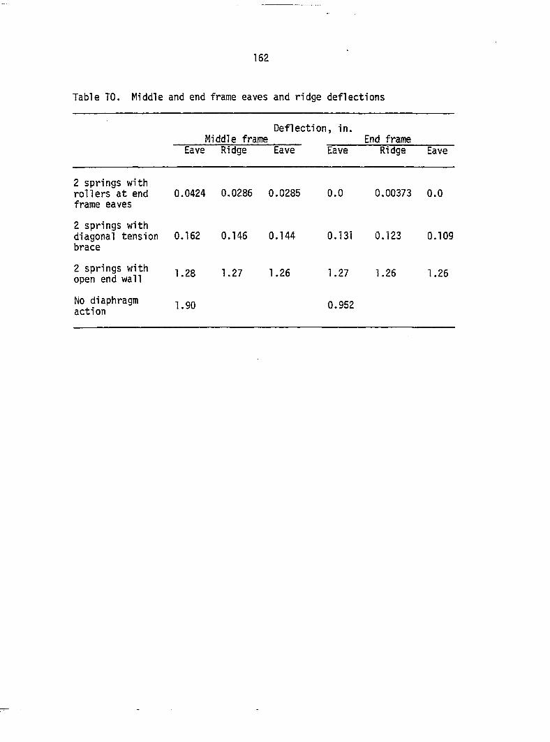
162
Table TO. Middle and end frame eaves and ridge deflections
Deflection, in. Middle frame End frame
Eave Ridge Eave Eave Ridge Eave
2 springs with rollers at end frame eaves
0.0424 0.0286 0.0285 0.0 0.00373 0.0
2 springs with diagonal tension brace
0.162 0.146 0.144 0.131 0.123 0.109
2 springs with open end wall
1.28 1.27 1.26 1.27 1.26 1.26
No diaphragm acti on
1.90 0.952
163
discrete individual resistances. The equation is sufficiently
accurate for building systems that have stiff diaphragms in comparison
to the frames and with few frames or building systems that have many
frames and relatively stiff frames when compared to the diaphragms.
Also, it is more convenient than the sets of simultaneous equations
describing the displacement of each frame/diaphragm if the procedure is
programmed. The equation is:
m. 1 - cosh (S /ETf) (13) cosh {j (n+l )A7c)
reduction factor, ratio of load carried by frame,
frame stiffness, lb/in.,
diaphragm stiffness, lb/in.,
number of frames in building, and
frame that reduction factor is for, 0 is center
frame; S=0, 1, 2, . .. n-1 for odd number of frames
and s= 1/2, 3/2, 5/2, . .. n-1/2 for even number of
frames.
Diaphragm Stiffness
To use diaphragm action in design, the frame and diaphragm
stiffnesses have to be known. The frame stiffness can be found by any
of a number of methods. The diaphragm stiffness can be found using
finite element or the simplified truss analogy presented in the
Results and Discussion Section of this dissertation. These two methods
can become very involved and require a lot of data preparation and input
where m =
K =
c =
n =
S =
164
time. Testing has been used in the United States, but the test results
are valid only for the diaphragm and any changes require a complete
replication of the test. Also, test data can be confusing since it
may not be obvious what components of slip are included.
Several investigators have worked on an analytical approach to
diaphragm stiffness (Bryan and El-Dakhakhni, 1968b; Bryan and Davies,
1975; Davies, 1976a; Easlcy, 1977; Ellifritt and Luttrell, 1971).
The analytical approach has the advantage of being simpler and it is
easier for designers to see what components will have the greatest
influence on the overall diaphragm behavior.
An analytical approach has been used to predict the stiffness of
diaphragms constructed of materials other than steel sheeting on steel
framing. Prins (1985) proposed a model to predict the stiffness of
composite diaphragms made of concrete placed over steel decking. The
procedure is based upon the assumption that because of the stiffness of
the concrete, the entire deck system acts as a single unit and the
diaphragm can be treated as being continuously connected to the edge
members. The metal sheeting on the wood frames does not act as a
single unit, but rather as individual sheets (Figure 79). Diaphragms
constructed of wood sheeting on wood frames have also been investigated.
The general approach is similar to the modeling of steel sheeted
diaphragms on steel frames, except for the sheeting (Tumoi and
McCutcheon, 1978; American Plywood Association, 1983). The sheeting
is flat and does not tend to distort like the corrugated profile does.
Also, there are usually several discontinuities in the length of the
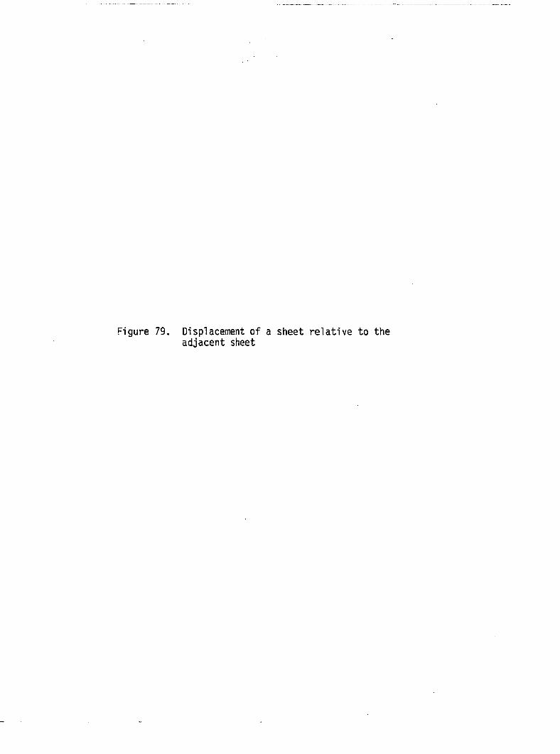
Figure 79. Displacement of a sheet relative to the adjacent sheet
166
167
diaphragm since these diaphragms are typically sheeted with plywood.
The next subsection will present an analytical model to predict
the stiffness of steel sheeted diaphragms on wood frames. The last
subsection of this section presents an empirical model to predict
diaphragm stiffness.
Analytical Model
There are several components that can make up the total displacement
of a diaphragm. The components that should be included are determined
from the components comprising the diaphragm, how the components are
assembled, and the way the frame and diaphragm interaction is going to
be modeled. The components that are important to diaphragms made of
steel sheeting on wood frames are presented by component.
Shear strain of sheeting
Several investigators have included the shear strain of the
sheeting in their analysis. One of the earlier ones was Luttrell (1565).
If one corrugation is evaluated as in Figure 80, it can be seen that
the total length of steel that must deform is the actual length of
steel in one corrugation divided by its projected length, K-|. The
shear strain, T, associated with the shear deflection is A/K^d, and the
shear stress is T = P/bt, where t is the uncoated sheet thickness and
the other terms are shown in Figure 80. The shear modulus, G, is
G = T/T (14)
168
n_
Figure 80. Shear strain deflection of a single corrugation
169
If the material is isotropic such as steel, then:
G = E/2 (1 + y) (15)
2 where E = modulus of elasticity of sheeting, lb/in , and
y = Poisson's ratio of sheeting.
Equating Eq. (14) to (15) and substituting values for x and Y:
Equation (16) is for one corrugation. There are a/d corrugations in
the diaphragm length perpendicular to the corrugations. Substituting
and letting P ^ 1 lb.:
where A is the displacement due to shear strain of sheeting per pound
of load (in/lb.).
Profile distortion of sheeting
The profile distortion of the sheeting is due to the sheeting not
being continuously fastened (Luttrell, 1965), and because the shear
center does not coincide with where the shear flow in the sheeting is
(Figure 8). The profile used in diaphragms on wood framed structures
tends to have ribs that are not very high nor wide when compared to
A = 2P K, d (1 + u)/Ebt . (16)
A = 2 a (1 + y)/Ebt (17)
170
profiles used in diaphragms on steel framed structures. Luttrell (1965)
proposed that this term could be found from testing of diaphragms. This
would require that all other components of the diaphragm's deflection be
known. Davies and Bryan (1982) used the energy method to derive the
following equation for profile distortion, assuming the deflected shape
could be modeled with a Fourier series:
^ = a d 4 S ^ (18) E t^'3 b'^
Equation (18) is the same as Eq. (6) and the terms are described there,
except A is deflection per unit load, in/lb. Davies has recently
revised the values for the profile distortion constant by using an
exponential and cosine function for the deflected shape
(Davies, 1986a; 1986b). The author has not evaluated the newer
expressions.
Sheet-purlin movement at sheet ends perpendicular to corrugation
The edge purlins are assumed to act as flanges for the diaphragm.
In doing so, the top purlin, side BC, must be in tension and the
bottom purlin, side AD, must be in compression. The force in the top
and bottom purlin must come from the sheeting if the purlin-rafter
connections behave as pins. The sheeting transfers this force through
the end fasteners (Easley, 1977). The force on each fastener tends
to be equal (Nilson and Ammar, 1974). If it is assumed that the sheets
do not move perpendicular to the corrugations, A , relative to each
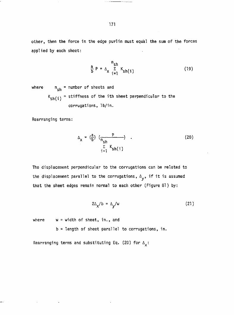
171
other, then the force in the edge purlin must equal the sum of the forces
applied by each sheet:
a "sh = (19)
where n^^ = number of sheets and
= stiffness of the ith sheet perpendicular to the Sii V I /
corrugations, lb/in.
Rearranging terms:
\ = (f ' • (2°)
i!l Ksh(i)
The displacement perpendicular to the corrugations can be related to
the displacement parallel to the corrugations, A^, if it is assumed
that the sheet edges remain normal to each other (Figure 81) by:
ZA^/b = Ayw (21 )
where w = width of sheet, in., and
b = length of sheet parallel to corrugations, in.
Rearranging terms and substituting Eq. (20) for A^:
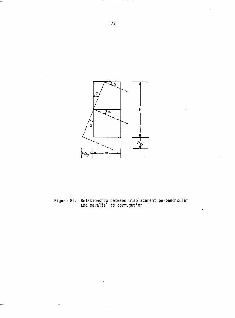
172
Figure 81. Relationship between displacement perpendicular and parallel to corrugation
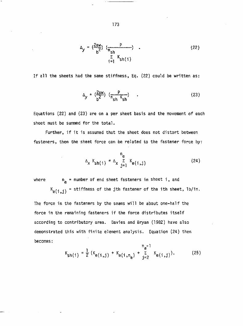
173
'y ' (?)
i=l Ksh(i)
If ail the sheets had the same stiffness, Eq. (22) could be written as:
Equations (22) and (23) are on a per sheet basis and the movement of each
sheet must be summed for the total.
Further, if it is assumed that the sheet does not distort between
fasteners, then the sheet force can be related to the fastener force by:
"e \ "e(i.j) (24)
where n^ = number of end sheet fasteners in sheet i, and
K /. = stiffness of the jth fastener of the ith sheet, lb/in.
The force in the fasteners by the seams will be about one-half the
force in the remaining fasteners if the force distributes itself
according to contributory area. Davies and Bryan (1982) have also
demonstrated this with finite element analysis. Equation (24) then
becomes :
V ^sh(i) ~ 2 ^^t(i,j) " '^e(i,ng) " ~ 9 (Kofi 4\ Kofi r, \ ^ (25)
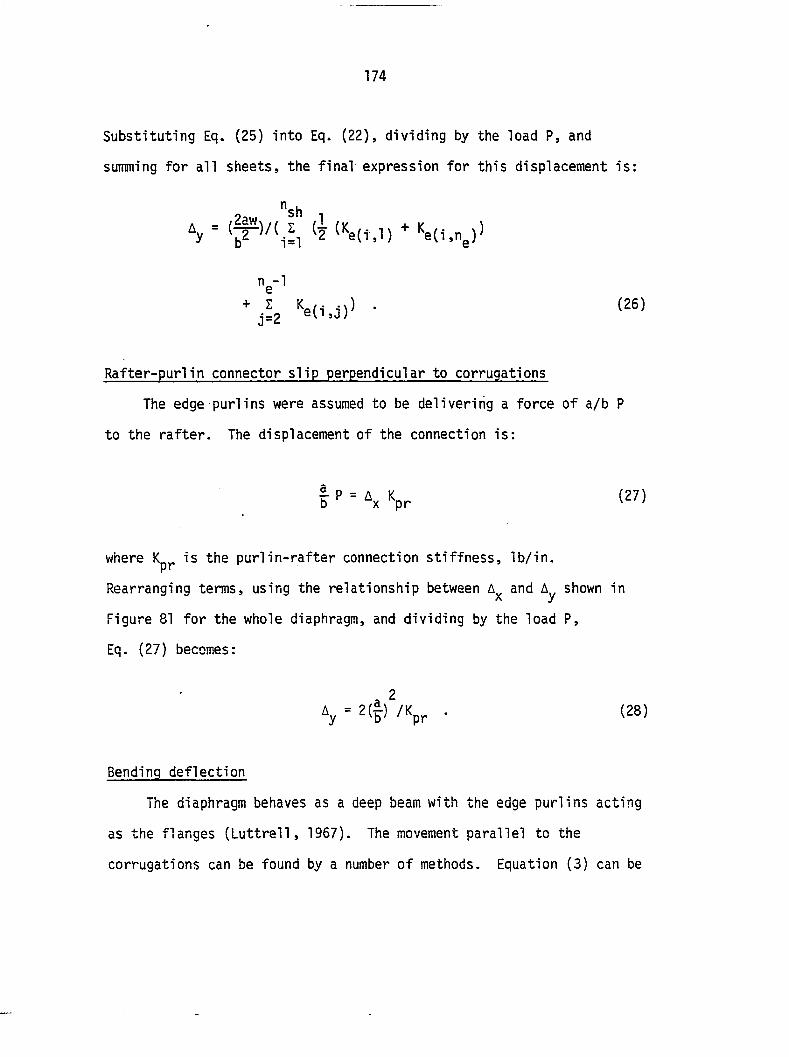
174
Substituting Eq. (25) into Eq. (22), dividing by the load P, and
summing for all sheets, the final expression for this displacement is;
,1 (i (Ke|,.l) + Ke(i.n,))
n^-l
• (26)
Rafter-purlin connector slip perpendicular to corrugations
The edge purlins were assumed to be delivering a force of a/b P
to the rafter. The displacement of the connection is:
V (27)
where is the purlin-rafter connection stiffness, lb/in.
Rearranging terms, using the relationship between A and A shown in X y
Figure 81 for the whole diaphragm, and dividing by the load P,
Eq. (27) becomes:
Ay = 2(§) /Kpr . (28)
Bending deflection
The diaphragm behaves as a deep beam with the edge purlins acting
as the flanges (Luttrell, 1957). The movement parallel to the
corrugations can be found by a number of methods. Equation (3) can be
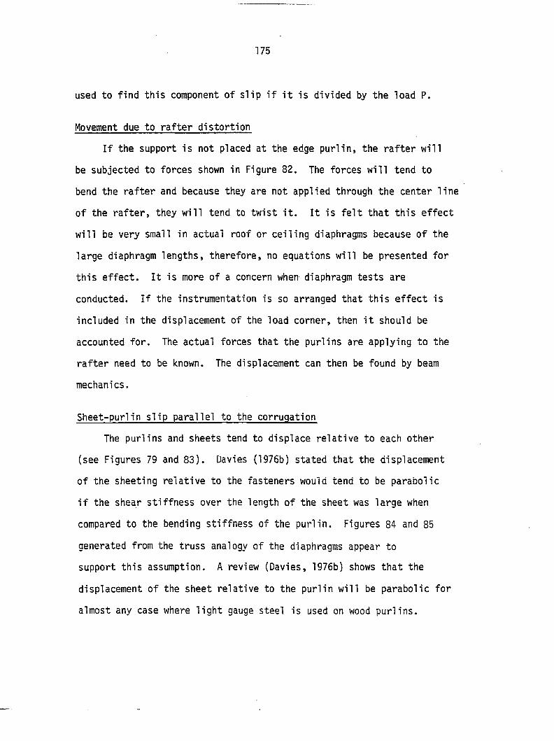
175
used to find this component of slip if it is divided by the load P.
Movement due to rafter distortion
If the support is not placed at the edge purlin, the rafter will
be subjected to forces shown in Figure 82. The forces will tend to
bend the rafter and because they are not applied through the center line
of the rafter, they will tend to twist it. It is felt that this effect
will be very small in actual roof or ceiling diaphragms because of the
large diaphragm lengths, therefore, no equations will be presented for
this effect. It is more of a concern when diaphragm tests are
conducted. If the instrumentation is so arranged that this effect is
included in the displacement of the load corner, then it should be
accounted for. The actual forces that the purlins are applying to the
rafter need to be known. The displacement can then be found by beam
mechanics.
Sheet-purlin slip parallel to the corrugation
The purlins and sheets tend to displace relative to each other
(see Figures 79 and 83). Davies (1976b) stated that the displacement
of the sheeting relative to the fasteners would tend to be parabolic
if the shear stiffness over the length of the sheet was large when
compared to the bending stiffness of the purlin. Figures 84 and 85
generated from the truss analogy of the diaphragms appear to
support this assumption. A review (Davies, 1976b) shows that the
displacement of the sheet relative to the purlin will be parabolic for
almost any case where light gauge steel is used on wood purlins.
176
^ P/2 Tension
P a/b
Tension
Compression
\ I Neutral /
Tension
Compression 1 1 ' Tension
tk
Pulls rafter
Pulls rafter
Pushes rafter
Pulls rafter
Pushes rafter
Pushes rafter
Figure 82. Rafter deflected shape if hinges are not placed at edge purlins
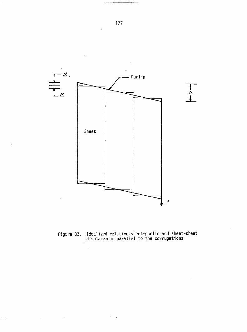
177
Ta
Purlin
Sheet
Figure 83. Idealized relative.sheet-purlin and sheet-sheet displacement parallel to the corrugations
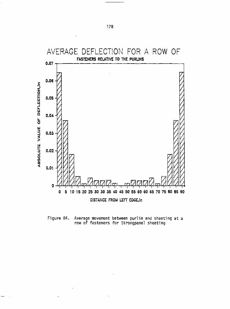
178
AVERAGE DEFLECTION FOR A ROW OF 0.07
0.06
0.05
0.04
0.03
0.02
0.01
0
Figure 84. Average movement between purlin and sheeting at a row of fasteners for Strongpanel sheeting
FASTENERS RELATIVE TO THE PURUNS
/
m f/i 1711711 / 1 [ I I 1 i 1 r 5 to 15 20 25 30 30 35 40
I I I I ! I I 1 I r 45 50 55 60 60 65 70 75 80 85 90
uidtAiNCL rrcuM ue.ri LUVL,in
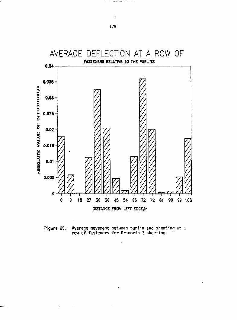
179
AVERAGE DEFLECTION AT A ROW OF FASTENERS RELATIVE TO THE PURUNS
6.04
0.035-
2 0.03 4
0.025 -
0.02-
z 0 I W Û
u. 0 u
3 5 W H 3 8 m <
0.015-
0.01
0.005
1.
77!
'A I '/I //
s 18 27 35 36 45 54 63 72 72 81 SO 99 108
DISTANCE FROM LEFT EDGE,In
Figure 85. Average movement between purlin and sheeting at a row of fasteners for Grandrib 3 sheeting
180
Reviewing Figures 86 and 87 shows that if the center line of the sheet
is used as the point of zero movement, then the equation representing
the displacement of the sheet relative to the purlin is different from
one side of the center line to the other (Figure 88). The two equations
for displacement parallel to the corrugations are:
where x is the distance the fastener is from sheet center line, in., and
A = ^ (A + A ) . (30) •y w
If the fastener pattern is consistent, then the displacement of one
sheet relative to the next, A^, is the sum of Eqs. (29) and (30).
The force on any particular sheet-purlin fastener or seam fastener is:
(29)
As = 26 + 'e (31)
(32) w i=l j=l
(33)
and
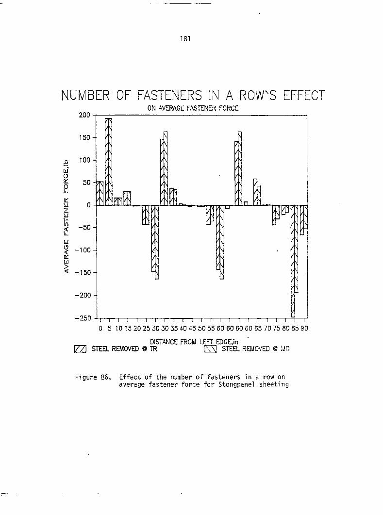
181
NUMBER OF FASTENERS IN A ROW'S EFFECT ON AVERAGE FASTENER FORCE
200
A 150-
100 -
-50 -
-100 -
< -150-
-250
0 5 10 15 20 25 30 30 35 40 45 50 55 60 60 60 60 65 70 75 80 85 90
DISTANCE FROM LEFT EDGE,in 1771 STEEL REMOVED @ TR [3 STEEL RE.MOVED ® r.!C
Figure 86. Effect of the number of fasteners in a row on average fastener force for Stongpanel sheeting
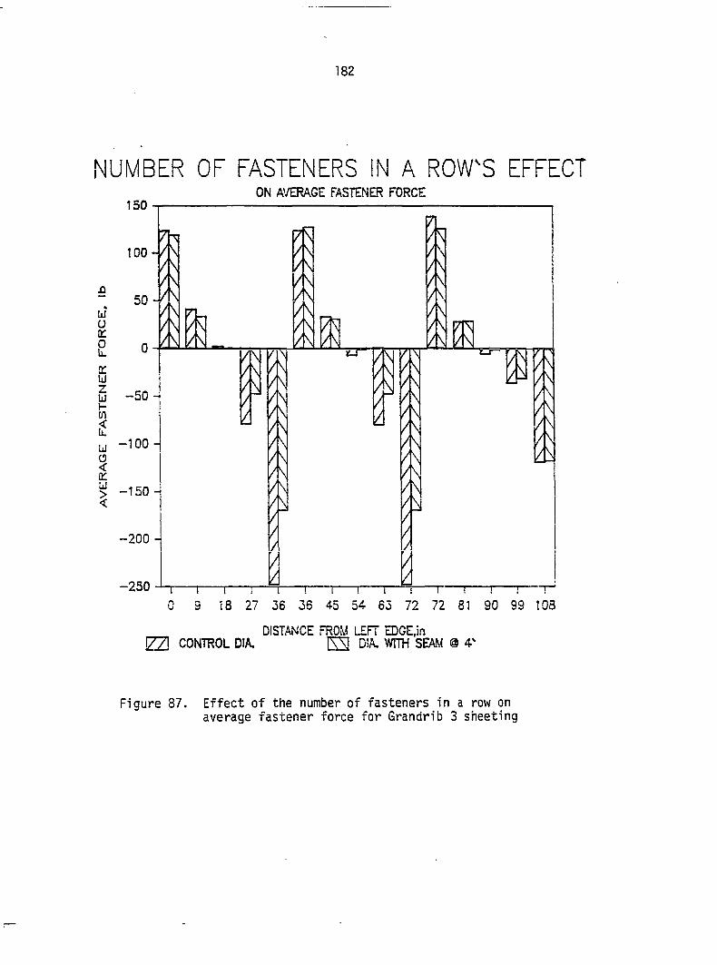
182
NUMBER OF FASTENERS IN A ROW'S EFFECT ON AVERAGE FASTENER FORCE
150
100-
/\ _/\ A
IM
—100 -
> -150 -
-200 -
-250 0 9 18 27 56 36 45 54 65 72 72 81 90 99 108
DISTANCE FROM LEFT EDGE.in iTTI CONTROL DIA. ÊS D!A. WITH SEAM 0
Figure 87. Effect of the number of fasteners in a row on average fastener force for Grandrib 3 sheeting
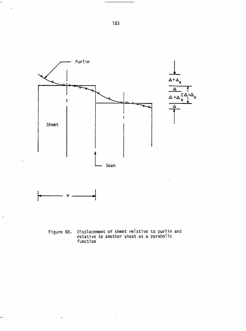
183
Purlin
A + A
Sheet
e
ETl"
A ~T~
— Seam
w
Figure 88. Displacement of sheet relative relative to another sheet as a function
to purlin and parabolic
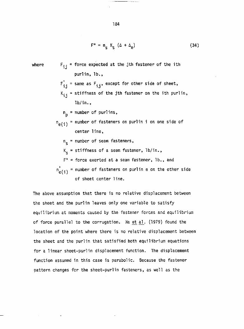
184
F" = Kg (A + àg) (34)
where F^j = force expected at the jth fastener of the ith
purlin, lb.,
plj = same as F\j, except for other side of sheet,
= stiffness of the jth fastener on the ith purlin,
lb/in.,
np = number of purlins,
"e(i) ~ number of fasteners on purlin i on one side of
center line,
n^ = number of seam fasteners,
Kg = stiffness of a seam fastener, lb/in.,
F" = force exerted at a seam fastener, lb., and
"e(i) " number of fasteners on purlin e on the other side
of sheet center line.
The above assumption that there is no relative displacement between
the sheet and the purlin leaves only one variable to satisfy
equilibrium at moments caused by the fastener forces and equilibrium
of force parallel to the corrugation. Ha ^ al_. (1979) found the
location of the point where there is no relative displacement between
the sheet and the purlin that satisfied both equilibrium equations
for a linear sheet-purlin displacement function. The displacement
function assumed in this case is parabolic. Because the fastener
pattern changes fcr the sheet-purlin fasteners, as well as the
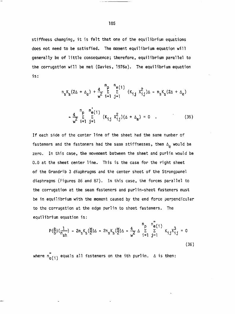
185
stiffness changing, it is felt that one of the equilibrium equations
does not need to be satisfied. The moment equilibrium equation will
generally be of little consequence; therefore, equilibrium parallel to
the corrugation will be met (Davies, 1976a). The equilibrium equation
is:
4 "P "e(i) 2 + Ae' ^ 7 (Kij - n^K^(2A + i^)
4 "P "e(i) , ^ E Z (K.• X..)(A + A ) - 0 . (35)
w*^ i=l j=l ®
If each side of the center line of the sheet had the same number of
fasteners and the fasteners had the same stiffnesses, then A^ would be
zero. In this case, the movement between the sheet and purlin would be
0.0 at the sheet center line. This is the case for the right sheet
of the Grandrib 3 diaphragms and the center sheet of the Strongpanel
diaphragms (Figures 85 and 87). In this case, the forces parallel to
the corrugation at the seam fasteners and purlin-sheet fasteners must
be in equilibrium with the moment caused by the end force perpendicular
to the corrugation at the edge purlin to sheet fasteners. The
equilibrium equation is:
n "
P ( & ) - 2 n K ( ^ ) A - 2 n K ( y ) A - A Z Z K - - X ? . = 0 ° "sh ^ ^ ^ ^ ^ wT i=l j=l
(36)
where equals all fasteners on the ith purlin. A is then:
186
"p "e A = 1/(2 n.K Z I K..xJ.) . (37)
^ ^ i=l j=l
Once A has been determined, A^ can be found from Eq. (38), which is:
"p "e(i) 2
A - : - 1 (A) (38)
"p "e(i) 2
The terms A and A^ have been determined on a per sheet basis and must
be summed for the entire diaphragm.
It should be noted that A^ should be found for one of the interior
purlins when such a large area of the diaphragm has no fasteners in it,
as is the case with the Grandrib 3 sheeting. The sheet being overlapped
has fasteners in the edge purlins only next to the rib of the seam.
This leaves approximately 142.5 in. before another fastener appears in
this row. Figure 87 shows that the average fastener force at 27 in. is
about 2.5 times that at 9 in. The same trend is followed when the
fastener force at 63 in. is compared to that at 45 in. It appears that
a substantial portion of the load normally found at the first row of
fasteners is carried by the second row of fasteners. The purlins in rows
27 in. and 63 in. deflect about 2.5 times farther from the sheet edge
than the purlins do at 9 in. and 45 in. according to the computer
analysis. The interior purlins are required to carry approximately one-
third the shear for a length of 9 in. Table 11 compares the computer
187
Table 11. Comparison of analytical hand-calculated stiffness to computer model calculated stiffness
Component of Equation Slip (in/lb.) slip Strongpanel Grandrib 3
S^sheetin^ " "-S"" 1°"* 5.5231 x 10"®
2.3179x10⁻⁵ 1.9271 x 10⁻⁵
Sheet-purlin slip _c ? perpendicular to 26 5.2553 x 10" 8.6412 x 10' corrugations
Sheet-purlin slip . c parallel to 37, 38 2.2826 x 10"^ 8.2052 x 10"^ corrugations
Total 2.6120 x 10"* 1.0771 x 10"^
Stiffness (lb/in.) 3828 9284
9145 Stiffness (lb/in.) ,772 Computer analysis
188
model predicted stiffness with that predicted by the hand-calculated
method.
Purlin-rafter slip parallel to the corrugations
When the purlins transfer the shear from the rafters to the
sheeting as is the case when shear connectors are not used or when the
sheeting is not attached to the rafters directly, the rafter-purlin
connection will be subjected to the shear force causing a movement of
this connection parallel to the corrugation and rafter. Assuming that
the slip at each rafter-purlin connection is the same, the shear will
be equal to:
"p P = A y (33)
where is the stiffness of rafter-purlin connection. Rearranging
terms, dividing by the shear force, and allowing for slip at each
rafter, Eq. (39) becomes:
"p A = 2/ Z K _ . (40)
i=l
Shear connector-sheet slip
It is generally assumed that when shear connectors are used, they
will transfer all the shear to the sheeting (Davies, 1975a). Equations
(35) - (38) would have to be adjusted. One of the seam fastener forces
would be replaced with the force on the sheeting due to the shear
connector-sheeting fasteners.
189
Fsc = "se "se (A + (41)
where = force on sheeting due to shear connector-sheeting
fastener, lb.,
"se ~ number of shear connector-sheeting fasteners,
= stiffness of shear connector-sheeting fasteners,
lb/in., and
Ag = displacement of shear connectors, in.
It then follows from Eq. (41) that Eq. (35) becomes:
. 4 "P "e(i) 2 "scf s c ( A + A ^ ) + (K.. x|.)A- n:Ks(2A + A^)
4 P e(i) 2 \ Z I (K,. xf.)(A + A„) = 0 . (42) / i=l j=i e
An additional equilibrium equation is necessary. If moments are taken
about the center of the sheet as was in the case of Eq. (37), the
equilibrium equation is:
" I ("scKsc)(A + .1^ (Kij Xij)A
1
Hp "e(i) - (?)(n_K )(2A + A ) - Z Z (K- • X?.)(A + A ) = 0 .
^ s s ® i=l j=l ®
(43)
190
Equations (42) and (43) can be solved simultaneously for and A^ once
A has been determined for another sheet, such as was discussed in the
development of Eq. (37).
If the fastener pattern is symmetric about the center line of the
sheeting, A^ would be zero and Eq. (42) would become:
"sc'^sc " "sS (ZA) = 0 (44)
and Ag would be equal to:
4 ' - "sc'<sc/"sc'^sc' • (45)
Further, if it is assumed that n K = n' k' , then a' would be equal
to A and Eq. (37) could be used at the edges (Davies, 1976a).
Shear connector-rafter slip
The shear connectors are fastened to the rafters as well as the
sheets and this connection is also subject to slip. This slip
component is derived the same as Eq. (40) and only the results will
be presented.
"sc A = 2/ Z K _ , (46)
i=l sc
where n^^ = number of shear connectors on rafter, and
= stiffness of a shear connector-rafter connection, lb/in.
191
Purlin shear strain and bending strain
If the sheet is not fastened to the purlin until some distance
past the rafter and shear connectors are not used, bending and shear
deflection of the purlin will influence the overall diaphragm stiffness
as was done with some of Hoagland's (1981) tests. If the first two rows
of sheet-purlin fasteners are assumed to act like hinges and the
rafter-purlin connections are hinged, then the following equation can
be derived for the resulting displacement (Appendix F):
A = fg((&'2/(&'_&)) _ £')/GAnp + t 'tZ/SEIn (47)
where f^ = form factor of purlin (Cowper, 1966; Gere and Timoshenko,
1984),
= distance from second row of fasteners to rafter, in.,
I = distance from first row of fasteners to rafter, in.,
2 G = shear modulus of purlin, lb/in ,
2 E = modulus of elasticity of purlin, lb/in , and
I = moment of inertia of purlin, in^.
Twisting of purlins
The loads applied to the purlins by the fasteners are not at the
centroid of the purlins. This will cause a twisting of the purlins. It
was observed in the tests by looking at the sheet fasteners that the
two ends of the purlins rotated in opposite directions. It was assumed
that the twisting of the purlins was due primarily to the shear
192
transfer from the rafters to the first row of fasteners. This in effect
makes the purlin behave as a shaft with a length equal to the width
of the diaphragm. Also, from observation, it was decided that the
purlin was attempting to rotate about a point where the corner of the
purlin touched the rafter.
A search of the literature (Foschi, 1974; Foschi and Bonac, 1977;
Lantos, 1969; Thomas and Malhota, 1985; Forest Products Laboratory, 1974)
did not turn up a suitable model for the distribution of fastener
forces in the purlins due to the connections. Most of the research
deals with the inelastic crushing of the wood around the fastener.
Observations of the nail holes in the purlins and rafters showed that
the wood was not being crushed. It was decided to use a force
distribution of a pole embedded in an elastic medium (American Wood
Preservers Institute, 1969). The wood was treated as being a
homogeneous isotropic material. Appendix G gives the derivation of
the slip due to purlin twist shown in Eq. (48):
A = 12.88a/Ep(I^ + Iy)np (48)
where I^ = moment of inertia of the purlin about its bottom
plane, in^, and
I^ = moment of inertia of the purlin about its side plane,
in'^ and
2 Ep = modulus of elasticity of purlin, lb/in .
193
Other considerations
The previous discussions concerning the components of slip of the
diaphragm were with the assumption that the diaphragm was behaving
elastically and that there were no large out-of-plane displacements.
The diaphragm sheeting can buckle out-of-plane in either the valleys
or buckling across the corrugation. Equation (49) gives the
critical shear stress which will cause buckling of the flats in the
valleys (Nilson, 1950a; 1960b).
where = shear stress that will cause local buckling, lb/in..
The small rises in the Strongpanel sheeting valleys were large enough
to act as stiffeners where the ones in Grandrib sheeting were not. No
local buckling or warping was noticed with the Strongpanel sheeting.
Davies and Bryan (1982) provide Equation (50) for checking for
buckling across the ribs:
= 5.4 TT^E/dZd - ;2)(h/t)2) (49)
2 E = sheeting modulus of elasticity, lb/in ,
li = Poisson's ratio of sheeting, and
h = unsupported flat length of the valley, in.
(50)
194
where P = load at which buckling occurs, lb.,
= bending stiffness of profiled sheet per unit length
3 7 perpendicular to corrugation; = E p / 12 K^(l - y ),
in-lb.,
Dy = bending stiffness of profiled sheet per unit length
parallel to corrugation; = I^E/d, in-lb.,
= moment of inertia of one corrugation about its neutral
• 4 axis, in , and
d = pitch of corrugations, in.
The term Op-l adjusts the length of the diaphragm for buckling to that
of the purlin spacing. After viewing the tests, it is felt that the
2 2 term (np-l/b) should be replaced by s in Eq. (50) if fasteners are
not in every valley, at the ribs, or next to the ribs. The distance,
s, would be from one fastener that prevents a rib from buckling to
the next fastener on the same rib that prevents the rib from buckling.
s will be greater than the purlin spacing if fasteners are omitted, as
was the case with the "Alternate Fastener Pattern" (Figure 33).
There are components of movement that were not addressed, such as
movement of the fasteners in the holes in the sheeting and shear
strain of the shear connectors. These components are either considered
to be small or unpredictable. It is up to the designer to decide what
components of slip are of importance to the problem at hand. For
instance, purlins being recessed may eliminate shear connectors, but
the shear may still be transferred to the sheeting without going
195
through the purlins.
Empirical equation
The following equation was derived by trial and error. The data
used for the derivation are from tests conducted on light gauge steel
diaphragms with steel framing (Luttrell and Ellifritt, 1970). Equation
(51) was developed for use with testing. The modified shear modulus of
the tested diaphragm can be used to determine the modified shear
modulus of diaphragms that are to be used in the field.
G" = Et/(2K^(1 + y) + Kg Kg
2 /((t/d)T'S (^) b(n, - l))1/2) (51)
"sh P
where Kg is the diaphragm constant determined from test conditions;
3/2 fastener pattern and type must be constant, in' . Kg can be found
from the modified shear modulus of the test diaphragm similar to the
procedure of the American Iron and Steel Institute (1957). The
diaphragm length, b, diaphragm thickness, t, and the number of
purlins, n^, were the only variables actually evaluated with Eq. (51).
The remaining variables are variables that often vary from one
diaphragm to the next. It was felt that a single equation to evaluate
the effect of the variables would be useful. Equation (51) shows that
the modulus of elasticity and thickness of the sheeting have the
largest effect and K-, and Poisson's ratio have the least effect. One
196
diaphragm from a series of diaphragms had all properties similar,
except for b, t, and n^. Kg was determined from this diaphragm and
the modified shear modulus was found for the remaining diaphragms with
Eq. (51). The test modified shear stiffness was divided by the
predicted. The mean of this ratio was 0.9836 with a standard
deviation of 0.19312. The model slightly over-predicts the test
result. Compared to the results given in Tables 1 and 2 (Liedtke and
Sherman, 1982), it would appear that Eq. (51) is satisfactory.
The test procedure that is recommended for use with Eq. (51)
would require a minimum of two tests:
1. If the two tested modified shear moduli, and Gg, are
within 10% of each other, use their average, G^ + G2/2.
2. If the tested values are not within 10% of each other,
conduct a third test, G^; then,
a) if is within 10% of G^, use (G^ + G2)/2,
b) if G-j is within 10% of G^, use (Gg + G,)/2, and
c) if is not within 10% of Gg nor G-j, use
(G-j + Gg + Ggj/S.
The above testing procedure would give a better estimate of the actual
modified shear modulus of the diaphragm. Equation (51) is very
sensitive to the starting value of G".
197
SUMMARY
From the results of this study, evaluation of proposed and existing
models, and in accordance with the objectives of this study, the
following conclusions can be made.
1. The size and location of an opening in the sheeting of a
diaphragm does affect its stiffness. In general, diaphragms with
approximately 11% of the sheeting removed and with the ends of all
sheets fastened the same as the edge purlins are fastened to the sheets
will have their stiffnesses reduced by 10% if the opening is sheeted on
three or more sides and by 20% if the opening is sheeted on two sides.
The least amount of effect is noted when the sheeting is removed
from the center of the diaphragms. The diaphragms with one-third of
the sheeting removed were basically ineffective as diaphragms. The
stiffness of these diaphragms is a function of the bending stiffness
of the purlins or rafters, depending upon configuration.
2. Recessing the purlins in from the ends of the sheeting
reduced the stiffness of the test diaphragms. The strain gauge
rosettes placed on diaphragms 15a and 16a showed that the sheeting
is not being stressed very much. Therefore, the reduction in
stiffness of the test diaphragms with recessed purlins is due to
factors other than the steel being ineffective past the edge fasteners.
3. Davies and Bryan's (1982) adjustment factor for more than one
sheet in the length of the diaphragm is valid for diaphragms of steel
198
sheeting on wood frames. The increased flexibility of the sheeting due
to the discontinuity of the sheet is greatly off-set by the increased
number of fasteners used at the seam. The use of several 12 ft. sheet
lengths would be stiffer than one larger sheet because of the increase
in fasteners used and the effect of more supporting purlins diminishes.
4. Reducing the number of fasteners at the center of the sheet
does not have a significant impact on diaphragm stiffness. The
fasteners at the sheet ends and sheet sides are much more critical.
5. Diaphragms which had the purlins flat were three and one-half
times stiffer than the diaphragms with the purlins on edge. It does
not appear that this effect is due to the increased moment of inertia
of the diaphragms, but rather the twisting of the purlins.
6. The axial strain in the edge purlins increases linearly with
load. The strain decreases with the increase in load prior to failure,
indicating that a portion of the load is being transferred to the
interior purlins. The actual failure mechanism may involve the added
displacement at the edge purlin due to the force in the interior
purlin.
7.- The strain in the sheeting is small. The shear strain of the
sheeting will be less than 7 1/2% of the total displacement. The
strain perpendicular to the corrugations is small and variable due to
local flat plate buckling in the valleys. The strain parallel to the
corrugations is basically insignificant, except at the corners of the
sheet where the force on the sheet-purlin fasteners is largest.
199
8. The fasteners are the governing factors in diaphragm stiffness.
Their placement and stiffness will be the most important factor.
9. The diaphragms at lower load ranges are stiffer than they
are when the entire portion of the linear curve is taken into account.
The truss analog used to analyze the diaphragms stiffness on the
average was within 5% of the test diaphragms stiffness for diaphragms
made of Strongpanel sheeting and within 15% of test diaphragms stiffness
for diaphragms made of Grandrib 3 sheeting. The larger variation for
the Grandrib 3 sheeting is due to a large variation in the fastener
stiffness. The results show that using the linear portion of the
curve to determine the diaphragm stiffness is closer to the diaphragm
stiffness predicted by analytical methods than using the portion of the
curve below 0.4 of the ultimate load.
10. The profile distortion constant for sheeting with small ribs
and large valleys can be taken-as being between 0.01 and 0.02. Most
profiles used on post frame structures would fall into this category.
11. The smaller stiffeners in the valleys of the Strongpanel
sheeting are effective in controlling localized flat plate buckling,
while those used in the Grandrib 3 sheeting are not.
12. . Compression buckling of the sheeting can occur behind valley
fasteners when the fastener is placed in the middle of the valley such
as is the case with the Strongpanel sheeting. Fasteners placed by the
rib, Grandrib 3 sheeting, will not be as prone to this because the rib
acts as a stiffener.
200
13. The rafter-purlin connection used in this test is not
adequate if full use of diaphragm action is to be made.
14. The truss analogy is satisfactory in predicting diaphragm
stiffness. There are several slip terms which should be added into the
flexibility thus determined for determination of the complete diaphragm
stiffness.
15. The analytical method predicted diaphragm stiffness for the
control diaphragms within 1.5% of the truss analogy. However, if
fastener patterns are symmetric about the sheet center line and the
same on all purlins, then the simpler equation proposed by Davies
{1976a) should be used.
16. When the interior purlin-sheet fastener pattern does not have
fasteners placed near the sheet edges, the interior fastener pattern
should be used in Eqs. (41-45) of the analytic method.
17. The plane truss/frame computer model will allow more accurate
modeling of diaphragm-frame interaction with buildings. The diaphragm
should be modeled by two springs rather than one when a complex
structural system such as a truss is involved.
18. An empirical equation was presented to predict diaphragm
stiffness from test results for different diaphragm lengths, sheet
thickness, and purlin spacing. The equation is sensitive to the
initial diaphragm modified shear modulus used to find the diaphragm
constant. Kg. Care needs to be taken to ensure that Kg is correctly
determined.
201
19. The different framing systems used in wood framed diaphragms
will include different slip components. The designer must be certain
to include the appropriate components of slip for the diaphragm being
designed.
202
RECOMMENDATIONS FOR CONTINUED RESEARCH
1. Determine the effect of repeat loading on the diaphragms'
stiffness.
2. Determine the effect of reverse loading on the diaphragms'
stiffness.
3. Determine the effect of the location of the sheet-purlin
fasteners around the ribs and valleys.
4. Determine the minimum distance from the edge of the sheet that
a fastener may be placed and still be effective where the sheets overlap.
5. Determine the effect of load parallel and perpendicular to the
grain of the wood on fastener stiffness.
6. Determine the stiffness of the purlin-rafter connections for
twisting of the purlins and the effect that the twisting has on the
sheeting.
7. Investigate the effect of leaving several sheet-purlin
fasteners out in a row.
8. Evaluate the diaphragm failure mechanisms to determine the
least catastrophic failure for design purposes.
9. Investigate the effect of including diaphragm action in the
design of post framed structures on the safety factors used in the
design process.
10. Derive a simpler empirical or analytical equation to predict
diaphragm stiffness for diaphragms with inconsistent screw patterns,
11. Determine the size and shape of small ridges in the valley
that will be effective as stiffeners.
203
12. Develop a method to determine the sheets profile distortion
constant, K^, that accounts for fastener location near the ribs and
stiffeners on the ribs.
13. Investigate the behavior of the diaphragms when the sheeting
and/or fasteners are behaving linearly and nonlinearly.
14. Develop a better analog to be used to determine the support
conditions for pole embedment. The analog should incorporate soil
characteristics and the elastic behavior of the soil.
15. Investigate the behavior of post-truss concentrations and
develop an appropriate analog to model this behavior.
16. Conduct full-scale tests to confirm that diaphragm properties
determined from cantilever tests and analytically can be applied
directly to frame-diaphragm interaction in a building.
204
BIBLIOGRAPHY
American Iron and Steel Institute. 1967. Design of light gage steel diaphragms. American Iron and Steel Institute, New York.
American Plywood Association. 1982. Design and fabrication of plywood stressed-skin panels: Supplement No. 3. American Plywood Association, Tacoma, WA.
American Plywood Association. 1983. Plywood diaphragms. Research Report 138. American Plywood Association, Tacoma, WA.
American Wood Preservers Institute. 1969. Pole building design. Fifth Edition. American Wood Preservers Institute, Washington, D.C.
Army, Navy, Air Force Manual. 1966. Seismic design for buildings. TM 5-809-10, Washington, D.C.
Arnold, V. E., L. F. Greimann, and M. L. Porter. 1978. Pilot tests of composite floor diaphragms. Progress Report ERI-79011. Engineering Research Institute, Iowa State University,. Ames, lA.
Atrek, E. and A. H. Nilson. 1980. Nonlinear analysis of cold-formed steel shear diaphragms. ASCE Journal of the Structural Division 106(ST3):693-710.
Beckwith, T. G. and N. L. Buck. 1969. Mechanical Measurements. Addison Wesley Publishing Company, Reading, MA.
Boone, G. R. 1987. Predicting the elastic behavior of metal-clad timber-framed diaphragms with an analytical model. Unpublished Master of Science Thesis, Pennsylvania State University, University Park, PA.
Boone, G. R. and H. B. Manbeck. 1985. Using existing models to predict diaphragm behavior. ASAE 85-4501. American Society of Agricultural Engineers, St. Joseph, MI.
Breyer, D. E. 1980. Design of wood structures. McGraw-Hill Book Company, New York.
Bryan, E. R. 1973. The stressed skin design of steel buildings. Crosby Lockwood Staples, London.
Bryan, E. R. 1975. Calculation of sheet steel diaphragms in the U.K. Pp. 491-533. ^ W. W. Yu and J. H. Senne, eds. Research and developments in cold-formed steel design and construction. Vol. II. Third International Specialty Conference on Cold-Formed Steel Structures. Department of Civil Engineering, University of Missouri-Rolla.
205
Bryan, E. R. 1976. Stressed skin design and construction: State of the art report. The Structural Engineer 54(9):347-351.
Bryan, E. R. and J. M. Davies. 1975. Stressed skin construction in the U.K. Pp. 569-598. l£ W. W. Yu and J. H. Senne, eds. Research and developments in cold-formed steel design and construction. Vol. II. Third International Specialty Conference on Cold-Formed Steel Structures. Department of Civil Engineering, University of Missouri-Roll a.
Bryan, E. R. and W. M. El-Dakhakhni. 1964. Behavior of sheeted post-frame sheds: Theory and experiments. Proceedings of the Institute of Civil Engineering 29:743-778.
Bryan, E. R. and W. M. El-Dakhakhni. 1968a. Shear flexibility and strength of corrugated decks. ASCE Journal of the Structural Division 94(ST11):2549-2580.
Bryan, E. R. and W. M. El-Dakhakhni. 1968b. Shear of corrugated decks: Calculated and observed behavior. Proceedings of the Institute of Civil Engineers 41:523-524.
Bryan, E. R. and P. Jackson. 1967. The shear behaviour of corrugated steel sheeting. Pp. 258-274. In_ K. C. Rockey and Harold V. Hill, eds. Thin walled steel structures. Gordon and Breach Science Publishers, New York.
Bryan, E. R. and M. E. Moshin. 1972. The design and testing of a steel building taking account of the sheeting. Ninth Congress Preliminary Report for the International Association for Bridge and Structural Engineering, Amsterdam. Pages 305-314.
Canada Plan Service. 1985a. Plywood ceiling diaphragm. M-9374. Canada Plan Service, Ottowa, Canada.
Canada Plan Service. 1985b. Steel roof diaphragm wind bracing with stud walls. M-9310. Canada Plan Service, Ottowa, Canada.
Chockalingam, S., P. Fazio, and K. Ha. 1978. Strength of cold-formed steel shear diaphragms. Pp. 673-699. In_W. W. Yu and J. H. Senne eds. Recent research developments in cold-formed steel structures Fourth International Specialty Conference on Cold-Formed Steel Structures. Department of Civil Engineering, University of Missouri-Rolla.
Countryman, D. 1952. Lateral tests on plywood sheathed diaphragms. Laboratory Report 55. Douglas Fir Plywood Association, Tacoma, WA
Cowper, G. R. 1966. The shear coefficient in Timoshenko's theory beam. The Journal of Applied Mechanics 33(2):335-340.
206
Dally, J. W. and W. F. Riley. 1965. Experimental stress analysis. McGraw-Hill Book Company, New York.
Davies, J. M. 1976a. Calculation of steel diaphragm behavior. ASCE Journal of the Structural Division 102(ST7):1411-1430.
Davies, J. M. 1976b. Light gage steel folded plates. The Structural Engineer 54(5):159-174.
Davies, J. M. 1977. Simplified diaphragm analysis. ASCE Journal of the Structural Division 103(ST11):2093-2109.
Davies, J. M. 1978. Developments in inexpensive lightweight structures. Pp. 701-723. Iji w. w. Yu and J. H. Senne, eds. Recent research developments in cold-formed steel structures. Fourth International Specialty Conference on Cold-Formed Steel Structures. Department of Civil Engineering, University of Missouri-Rolla.
Davies, J. M. 1986a. A general solution for the shear flexibility of profiled sheets. I: Development and verification of method. Thin-Walled Structures 4:41-68.
Davies, J. M. 1986b. A general solution for the shear flexibility of profiled sheets. II: Application of the method. Thin-Walled Structures 4:151-161.
Davies, J. M. and E. R. Bryan. 1979. Design tables for light gauge steel diaphragms. Pp. 605-619. In^ J. Rhodes and A. C. Walker, eds. Thin-walled structures. John Wiley and Sons, New York.
Davies, J. M. and E. R. Bryan. 1982. Manual of stressed skin diaphragm design. John Wiley and Sons, Inc., New York.
Davies, J. M. and R. M. Lawson. 1975. The shear flexibility of corrugated steel sheeting. Pg. 535-568. In^W. W. Yu and J. H. Senne, eds. Research and developments in cold-formed steel design and construction. Vol. II. Third International Specialty Conference on Cold-Formed Steel Structures. Department of Civil Engineering, University of Missouri-Rolla.
Davies, J. M. and R. M. Lawson. 1978. The shear deformation of profile metal sheeting. International Journal for Numerical Methods in Engineering 12:1507-1541.
Easley, J. T. 1975. Buckling formulas for corrugated metal shear diaphragms. ASCE Journal of the Structural Division 101(ST7): 1403-1417.
207
Easley, J. T. 1977. Strength and stiffness of corrugated metal shear diaphragms. ASCE Journal of the Structural Division 103(ST1): 169-180.
Easley, J. T. and D. E. McFarland. 1969. Buckling of light-gage corrugated metal shear diaphragms. Proceedings of the ASCE, Journal of the Structural Division 95(ST7):1497-1516.
El-Dakhakhni, W. M. 1967. Discussion of "The shear behavior of corrugated steel sheeting". Pp. 291-294. %n K. C. Rockey and Harold V. Hill, eds. Thin walled steel structures. Gordon and Breach Science Publishers, New York.
El-Dakhakhni, W. M. 1976. Shear of light-gage partitions "in tall buildings. ASCE Journal of the Structural Division 102(ST7): 1431-1447.
Ellifritt, D. S. and L. D. Luttrell. 1971. Strength and stiffness of steel deck shear diaphragms. Pp. 111-117. In. W. W. Yu, ed. First Specialty Conference on Cold-Formed Steel Structures. Department of Civil Engineering, University of Missouri-Rolla.
Falkenberg, J. C. 1969. Discussion of "Shear flexibility and strength of corrugated decks". Proceedings of the ASCE. Journal of the Structural Division 95(ST6):1382-1386.
Forest Products Laboratory. 1974. Wood Handbook: Wood as an engineering material. Agricultural Handbook No. 72. U.S. Department of Agriculture, Washington, D.C.
Foschi, R. 0. 1974. Load-slip characteristics of nails. Wood Science 7{l):69-76.
Foschi, R. 0. and T. Bonac. 1977. Load-slip characteristics for connections with common nails. Wood Science 9(3):118-123.
Gebremedhin, K. G. and J. A. Bartsch. 1984. Optimization of pole-frame design. ASAE 84-4506. American Society of Agricultural Engineers, St. Joseph, MI.
Gebremedhin, K. G. and W. W. Irish. 1984. An experimental investigation of diaphragm behavior for farm buildings. ASAE 84-4511. American Society of Agricultural Engineers, St. Joseph, MI.
Gebremedhin, K. G. and M. C. Jorgensen. 1985. Design height for modern post-frame buildings using diaphragm theory. ASAE 85-4502. American Society of Agricultural Engineers, St. Joseph, MI.
208
Gere, J. M. and S. P. Timoshenko. 1984. Mechanics of materials. Second Edition. Brooks/Cole Engineering Division, Monterey, CA.
Granite City Steel, ca. 1981. Strongpanel diaphragm strength tests. Granite City Steel, Granite City, IL.
Gurfinkel, G. 1973. Wood engineering. Southern Forest Products Association, New Orleans, LA.
Ha, H. K. 1979. Corrugated shear diaphragms. ASCE Journal of the Structural Division 105(ST3):577-587.
Ha, H. K., S. Chockalingam, and P. Fazio. 1979. Further study on the strength of cold-formed shear diaphragms. Pp. 642-557. In^ J. Rhodes and A. C. Walker, eds. Thin-walled structures. John Wiley and Sons, New York.
Hausmann, C. T. and M. L. Esmay. 1975. Pole barn wind resistance design using diaphragm action. ASAE 75-4035. American Society of Agricultural Engineers, St. Joseph, MI.
Hausmann, C. T. and M. L. Esmay. 1977. The diaphragm strength of pole buildings. Transactions of the American Society of Agricultural Engineers 20(1):114-116.
Higdon, A., E, H. Ohlsen, W. B. Stiles, and J. A. Weese. 1967. Mechanics of materials. Second Edition. John Wiley and Sons, Inc., New York.
Hoagland, R. C. 1981. Strength and stiffness of screw-fastened roof panels for pole buildings. M.S. Thesis, Iowa State University, Ames, lA.
Hoagland, R. C. and D. S. Bundy. 1981. Applying diaphragm theory to post frame design. ASAE 81-4506. American Society of Agricultural Engineers, St. Joseph, MI.
Hoagland, R. C. and D. S. Bundy. 1983a. Post-frame design using diaphragm theory. Transactions of the American Society of Agricultural Engineers 26(5):1499-1503.
Hoagland, R. C. and D. S. Bundy. 1983b. Strength and stiffness of screw-fastened roof panels for pole buildings. Transactions of the American Society of Agricultural Engineers 26(2):512-515.
Home, M. R. 1966. Discussion of "Behavior of hseeted portal frame sheds: Theory and experiments". Proceedings of the Institute of Civil Engineering 34:231-234.
209
Home, M. R. and R. A. S. Raslan. 1971a. An energy solution to the shear deformation of corrugated plates. International Association for Bridge and Structural Engineering 31(I):51-72.
Home, M. R. and R. A. S. Raslan. 1971b. A finite difference approach to corrugated shear panels. International Association for Bridge and Structural Engineering 31(I):73-92.
Hoyle, R. J., Jr. 1978. Wood technology in the design of structures. Fourth Edition. Mountain Press Publishing Company, Missoula, MT.
Huang, H. T. and L. D. Luttrell. 1980. Theoretical and physical evaluation of steel shear diaphragms. Pp. 301-329. In^ W. W. Yu and J. H. Senne, eds. Recent research and design trends in cold-formed steel structures. Fifth International Specialty Conference on Cold-Formed Steel Structures. Department of Civil Engineering, University of Missouri-Rolla.
Hurst, H. T. and P. H. Mason, Jr. 1961. Rigidity of end walls and cladding on pole buildings. Journal of the American Society of Agricultural Engineers 42(4):188-191.
Johnston, R. A. 1980. Stressed skin design of pole framed buildings. M.S. Thesis, University of Illinois, Urbana, IL.
Johnston, R. A. and J. 0. Curtis. 1982. Stressed-skin design of pole-frame buildings. ASAE 82-4075. American Society of Agricultural Engineers, St. Joseph, MI.
Johnston, R. A. and J. 0. Curtis. 1984. Experimental verification of stress skin design of pole-frame buildings. Transactions of the American Society of Agricultural Engineers 27(1):159-164.
La Boube, R. A. and J. M. Fisher. 1982. Diaphragm strength of composite roof system. Pp. 391-407. In_ W. W. Yu and J. H. Senne, eds. Recent research and developments in cold-formed steel design and construction. Sixth International Specialty Conference on Cold-Formed Steel Structures. Department of Civil Engineering, University of Missouri-Rolla.
Lantos, G. 1969. Load distribution in a row of fasteners subjected to lateral load. Wood Science 1(3):129-136.
Liedtke, P. E. and D. R. Sherman. 1982. Comparison of methods predicting diaphragm behavior. Pg. 369-389. In_ W. W. Yu and J. H. Senne, eds. Recent research and developments in cold-formed steel design and construction. Sixth International Specialty Conference on Cold-Formed Steel Structures. Department of Civil Engineering, University of Missouri-Rolla.
210
Little, D. H. 1966. Discussion of "Behavior of sheeted portal frame sheds: Theory and Experiments". Proceedings of the Institute of Civil Engineering 34:236-237.
Luttrell, L. D. 1965. Structural performance of light gage steel diaphragms. Ph.D. Dissertation, Cornell University, Ithaca, NY.
Luttrell, L. D. 1967. Strength and behavior of light-gage steel diaphragms. Cornell Engineering Research Bulletin 67-1. American Iron and Steel Institute, New York.
Luttrell, L. D. 1981. Steel Deck Institute diaphragm design manual. Steel Deck Institute, Canton, OH.
Luttrell, L. D. and D. S. Ellifritt. 1970. The strength and stiffness of steel deck subjected to in-plane loading. Steel Deck Institute, Canton, OH.
Measurements Group., Inc. 1976. Surface preparation for strain gauge bonding. B-129-4. Measurements Group, Inc., Raleigh, NC.
Measurements Group, Inc. 1979. Strain gauge installation with M-bond 200 adhesive. B-127-9. Measurements Group, Inc., Raleigh, NC.
Measurements Group, Inc. 1982. General instructions for the selection and use of tens-lac brittle laquer and undercoating. 215-C. Measurements Group, Inc., Raleigh, NC.
Measurements Group, Inc. 1983a. Strain gauge selection: Criteria, procedure, recommendations. TN-505. Measurements Group, Inc., Raleigh, NC.
Measurements Group, Inc. 1983b. Soldering techniques for lead attachment strain gauges with solder data. TT-606. Measurements Group, Inc., Raleigh, NC.
Midwest Plan Service. 1975. Pole design. TR-5. Midwest Plan Service, Iowa State University, Ames, lA.
National Forest Products Association. 1986a. Nation design specifications for wood construction. National Forest Products Association, Washington, D.C.
National Forest Products Association. 1986b. Design values for wood construction. National Forest Products Association, Washington, D.C.
Nil son, A. H. 1956. Deflection of light gage steel floor systems under the action of horizontal loads. M.S. Thesis, Cornell University, Ithaca, NY.
211
Nil son, A. H. 1960a. Shear diaphragms of light gage steel. Proceedings of the ASCE Journal of the Structural Division 86{ST11):111-139.
Nilson, A. H. 1960b. Diaphragm action in light gage steel construction. American Iron and Steel Institute, New York.
Nilson, A. H. and A. R. Ammar. 1974. Finite element analysis of metal deck shear diaphragms. ASCE Journal of the Structural Division 100(ST4):711-726.
Prins, M. D. 1985. Elemental tests for the seismic resistance of composite floor diaphragms. M.S. Thesis, Iowa State University, Ames, lA.
Ravindra, M. K. and T. V. Galambos. 1978. Load and resistance factor design for steel. ASCE Journal of the Structural Division 104(ST9):1337-1353.
Rothwell, A. 1967. The shear stiffness of flat-sided corrugated webs. The Aeronautical Quarterly 19(3):224-234.
Sherman, D. and J. Fisher. 1971. Beams with corrugated webs. Pp. 198-204. In_ W. W. Yu, ed. First Specialty Conference on Cold-Formed Steel Structures. Department of Civil Engineering, University of Missouri-Rolla.
Stark, J. W. B. and A. W. Toma. 1979. Fastening of steel sheets for walls and roofs on steel structures. Pp. 588-598. In_ J. Rhodes and A. C. Walker, eds. Thin-walled structures. John Wiley and Sons, New York.
Tarpy, T. S., Jr., D. J. Thomas and L. A. Soltis. 1985. Continuous timber diaphragms. Journal of Structural Division 111(5):992-1000.
Thomas, S. T. 1980. Shear resistance of steel-stud wall panels. Pp. 331-348. jn^ w. w. Yu and J. K. Senne, eds. Recent research and design trends in cold-formed steel structures. Fifth International Specialty Conference on Cold-Formed Steel Structures. Department of Civil Engineering, University of Missouri-Rolla.
Thomas, B. and S. K. Malhota. 1985. Behavior of timber joints with multiple nails. Journal of Structural Engineering 111(5);973-990.
Timoshenko, S. P. and J. N. Goodier. 1970. Theory of elasticity. Third Edition. McGraw-Hill Book Company, New York,
Tuomi, R. L. and W. J. McCutcheon. 1978. Racking strength of light-frame nailed walls. ASCE Journal of the Structural Division 104(ST7):1131-1140.
212
Turhbull, J. E. 1981. A summary of Canada Plan Service diaphragm design for wind bracing in farm buildings. ASAE 81-4505. American Society of Agricultural Engineers, St. Joseph, MI.
Turnbull, J. E. and S. M. Guertin. 1975. Shear and buckling resistance of cladding materials used as structural diaphragms in farm buildings. Transactions of Canadian Agricultural Engineers 17(1):7-11.
Turnbull, J. E., J. A. Thompson, and A. T. Ouaile. 1985. Steel roof diaphragms for wind bracing in agricultural buildings. CSAE 85-405. Canadian Society of Agricultural Engineers, Monoton, New Brunswick.
Warshaw, C. 1979. Performance of aluminum shear diaphragms. M.S. Thesis, Cornell University, Ithaca, NY.
White, R. N. 1978. Diaphragm action of aluminum-clad timber-frame buildings. ASAE 78-4501. American Society of Agricultural Engineers, St. Joseph, MI.
Yu, W. 1986. Cold-formed steel design. John Wiley and Sons, Inc., New York. (Also published by Interscience in 1985.)
213
ACKNOWLEDGMENTS
The research was conducted with steel sheeting, lumber, and
fasteners that were provided by FA3RAL Alcan Building Products, a
division of Alcan Aluminum Corporation, and Granite City Building
Products, National Steel Corporation. Both companies also provided
technical data on the sheeting, fasteners, and fabrication details.
The author wishes to express sincere appreciation to Dr. D. S.
Bundy, Department of Agricultural Engineering, for serving as major
professor and for his assistance in the study.
Appreciation for assistance in the study and overseeing my graduate
course work is also extended to committee members: Dr. C. J. Bern,
Agricultural Engineering Department; Dr. L. F. Greimann, Civil
Engineering Department; Dr. F. W. Klaiber, Civil Engineering Department;
Dr. J. H. Pedersen, Agricultural Engineering Department; and Dr. R. J.
Smith, Agricultural Engineering Department. The author also wishes
to acknowledge the contributions made to the experimental work by lab
technicians Marc Lott, Milt Moyer, and Doug Wood, and graduate student
Alan Lukens.
The author is very thankful for continuous support, patience, and
understanding of his wife, Joanne, during the study.
214
APPENDIX A: EFFECT OF TWO DIAPHRAGMS ACTING TOGETHER
Luttrell's (1965) equation for the modified shear modulus:
G" = ^ 9 (52) 2(l+u)K^ + K^/{htr
where G" = modified shear modulus of diaphragm, lb/in.,
(Pa/Agb),
2 E = modulus of elasticity of sheeting, lb/in ,
t = uncoated thickness of sheeting, in.,
y = Poisson's ratio of sheeting,
K-j = ratio of length of material in one corrugation to
the projected length of the element,
b = length of diaphragm parallel to corrugation, in..
Kg = diaphragm constant for a given corrugation cross-
4 section and end fastener pattern, in ,
a = length of diaphragm perpendicular to corrugation, in.,
and
Ag = shear deflection of diaphragm under load P- in.
(P in lb.).
From Johnston (1980):
215
where C is the shear stiffness, lb/in. (P/Ag), and all other terms
are defined above. Johnston's data:
E = 30,000,000 Ib/in^
t = .0172 in. (note: uncoated thickness .0135 in.)
y = .3
K-j - 1.3
b = 144 in. test diaphragm
b = 276 in. building diaphragm
c = 822 lb/in. test diaphragm
a = 108 in.
From Eq. (53), C = 2977 lb/in. Johnston concluded that to match
test data, the roof diaphragm shear stiffness should be 11900 lb/in.
This is approximately a factor of four, which could be obtained by
letting b = 2b (both roof halves). From American Iron and Steel
Institute (1967) pages 21-23:
G" = C (a/b)
= 822 (108/144)
= 616.5 lb/in. for test diaphragm.
From Eq. (52), Kg = 2470 in^. Therefore, from Eq. (52),
G" = 2234 lb/in. If both halves of the roof deflect the same amount
horizontally, then
"rtlT
216
(54)
P = + PG (55)
where P-j = load carried by one roof diaphragm,
Pg = load carried by other roof diaphragm,
P = total load,
b-j = length of one roof diaphragm,
bg = length of other roof diaphragm,
6!|' = modified shear modulus of one roof diaphragm, and
Gg = modified shear modulus of other roof diaphragm.
Note that g!|' = Gg = G" and b^ = bg = b. From Eq. (54):
G"A^b Pi =
G"A b
G"A b G"A b p = p + p = ^ ' 5
1 '2 a a
2G"A b p = L_
2G" - Pa A^b
217
G" = (for both diaphragms),
but
PJ_ ^s
G" = (for one diaphragm)
Therefore, G" (both diaphragms) = 2G" (one diaphragm)
= 2(2234)
= 4468 lb/in.
and
C = G"(b/a)
= 4468 (275/108)
= 11418 lb/in.
11418/2977 = 3.84 is the stiffness Johnston needed to match his test
data.
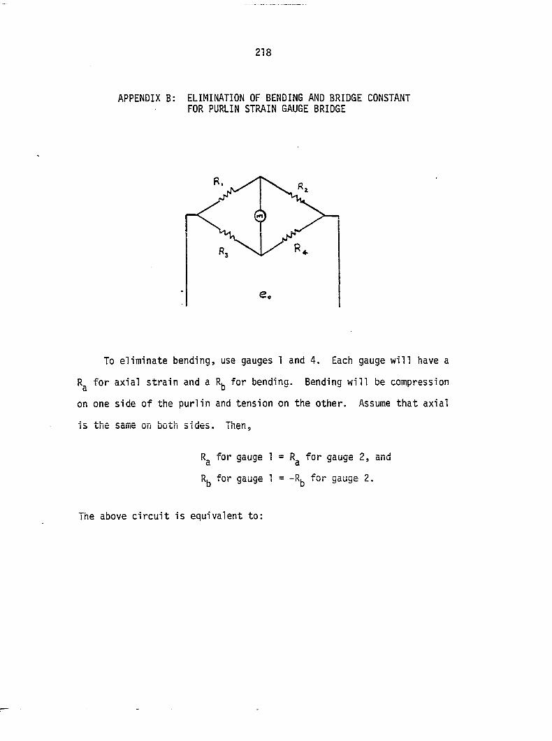
218
APPENDIX B: ELIMINATION OF BENDING AND BRIDGE CONSTANT FOR PURLIN STRAIN GAUGE BRIDGE
To eliminate bending, use gauges 1 and 4. Each gauge will have a
R^ for axial strain and a for bending. Bending will be compression
on one side of the purlin and tension on the other. Assume that axial
is the same on both sides. Then,
Rg for gauge 1 = R^ for gauge 2, and
R^ for gauge 1 = for gauge 2.
The above circuit is equivalent to:
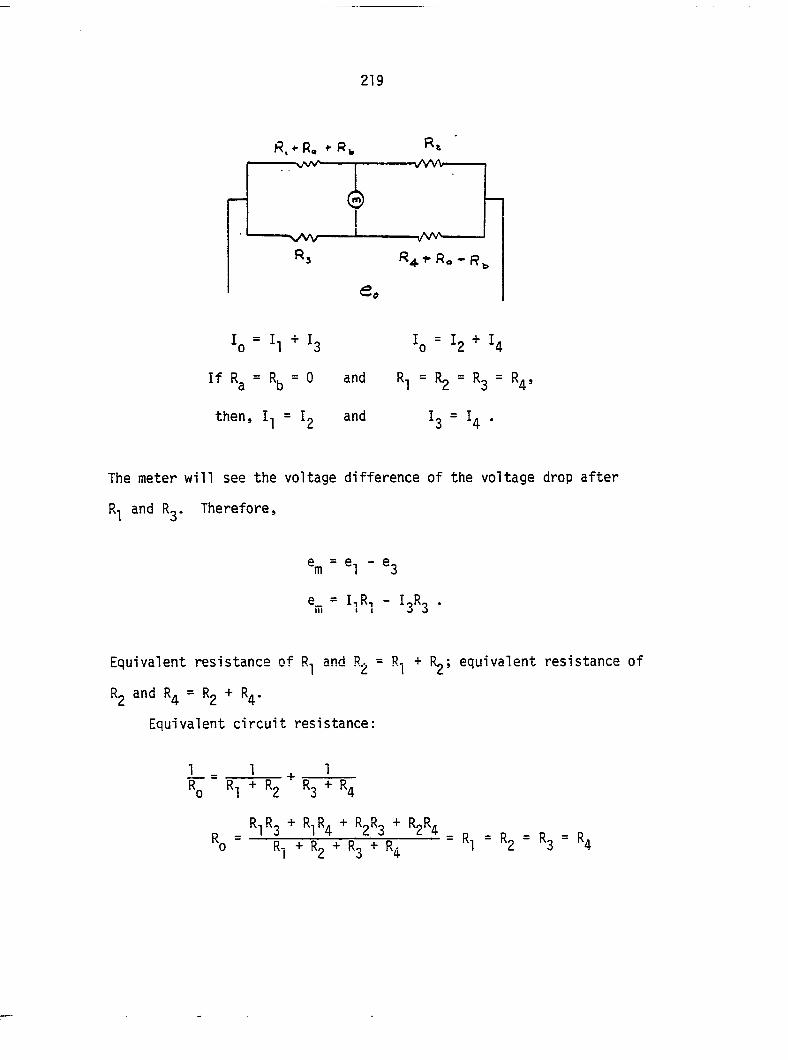
219
K, + R« ^ f w vwv
0
N/W
'o ' I, + '3
If Rg = Rfa = 0 and
then, I-j = Ig and
lo = :2 + U
R-, = R2 = R3 =
^3 U •
The meter will see the voltage difference of the voltage drop after
R-j and Ry Therefore,
=m = *1 - "3
G_ - IlRi - IgR? I l l I I V u
Equivalent resistance of R^ and Rg = R-j + Rg; equivalent resistance of
Rg and R^ = Rg + R^.
Equivalent circuit resistance:
1_ R. Rl + Rg R3 + R4
"0 ° = R, = "2 = «3 = «4
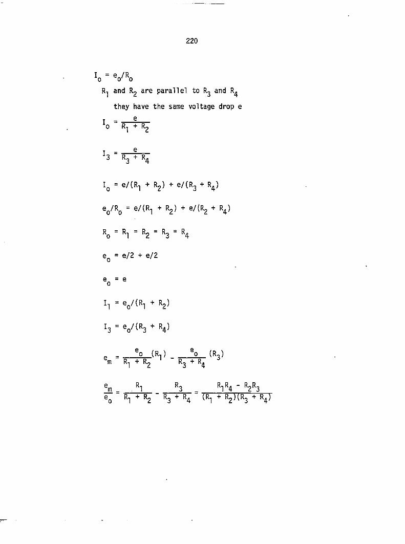
220
and Rg are parallel to Rg and R^
they have the same voltage drop e
T — G
0 + R2
T = ^ 3 " R3 + "^4
Iq = e/(R^ + Rg) + e/(R3 + R^)
V^o " G/(Ri + Rg) + e/fRg + R^)
Ko ' *1 = *2 = *3 ' K4
e^ = e/2 + e/2
e = e 0
Il ' Vf"! * "Z*
I3 = e„/(R3 + R4)
e - °° ("i) (R]) % + Rg "3 "4
fa = "i __ "3 ^ R1R4 - R2R3 ®Q R^ + R2 R3 R4 tR^] ^ * R4)
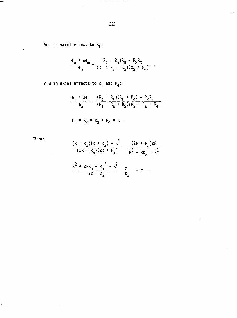
221
Add in axial effect to R-j :
®0 (Rl + Rg + + R4)
Add in axial effects to R^ and R^:
% "• <"1 * "a'^^a " *2*3 % ' ("i + «a + ^ "a *
Rl = R2 = R3 = R4 = R .
Then : « (R + Rg)(R + Rg) - R^ (2R + Rg)2R
(2R + R^)(2R + R^)
R^ + 2RR, + R^ - R^ , Ê Ê L - = 2
2R + R, R, ^ • a a
222
APPENDIX C: DYNOMETER CALIBRATION
Dynometer reading Satech 400 HVL *0 • \ Error, E X.(lb) test frame 0 S (from least
S X,(1b) D(lb) squares)
1000 1000 0 2 1440 1500 10 -1 1980 2000 20 -4 2460 2500 40 3 2950 3000 50 0
Total 9880 10000 120 0
After observing the plot of D vs. (Figure 89), it would appear that
the dynometer is unbiased from 0-1000 lb. and biased between 1000 and
3000 lb. Therefore, only use the data for X^ ^ 1000 lb.
D = 120/5
= 24
Sn = ( z D. - D)Z/(n - 1))'/Z
= 20.7364 .
The test is to determine if the dynometer is biased from 1000 to 3000
lb. assuming a normal distribution. Therefore,
"o : "D = 0
"A : "O f 0
223
50
DIFFERENCE VS. LOAD DYNOMETER CAUSRATION
40 -
30-
20
1 0 -
1—r 1 I ! ! ! I r !
0 0.4 0.8 1.2 1.6 (Thousands)
ACTUAL LOAD,Xo,lb
2.4 2.8
Figure 89. Difference between Satech 400 HVL test frame and dynometer readings
224
t = VrTCD - Up)/Sp
= y^(24 - 0)720.7364
= 2.5880
= 1.530 a = .2
= 2.132 ct = .1
= 2.776 a = .05
= 4.601 a = .005
At the 10% significance level, t > 2.132. Reject the dynometer
is bias. If the bias is assumed to be linear, then:
D = .026XQ - 28 + E (by least squares)
- 28
-Xg = -.974Xq - 28
X = 1.0267X - 28.7474 (correction of dynometer ° ^ reading)
Note that 1000 lb. was in the unbiased range. Correct values above
1000 lb.
225
APPENDIX D: SCREW FASTENER STIFFNESS^
Allowable load per fasteners:
P = K
K = 3240 Wood Group III (Gurfinkel, 1973)
D = 0.19 in. (#10 screw)
P = 3240 (.19)2
= 117 lb. (National Forest Products Association, 1986a)
Reduction for penetration: (National Forest Products
Association, 1986a)
Preferred penetration: 7D = 1.33 in.
Actual penetration: 1-steel thickness-washer thickness
1-0.0172 - 0.125
0.8578 in.
Adjustment: 0.8578/1.33 = 0.6450
Increase for use of metal plate: (National Forest Products
1.25 Association, 1986a)
Adjustment: 1.25 (0.6450) = 0.8062
Allowable load: p = 0.8062(117)
= 94.3 lb.
This load is for resulting slip between 0.007 in. and
0.01 in. (Forest Products Laboratory, 1974).
^National Forest Products Association, 1986a.
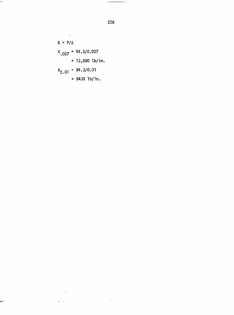
K = P/A
K QQ7 = 94.3/0.007
= 13,500 lb/in.
Kg.Ol = 94.3/0.01
= 9430 lb/in.
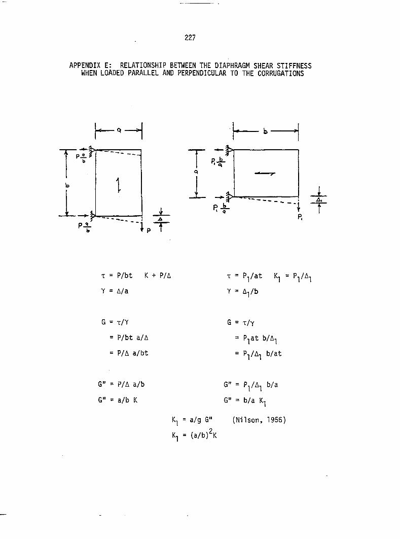
227
APPENDIX E: RELATIONSHIP BETWEEN THE DIAPHRAGM SHEAR STIFFNESS WHEN LOADED PARALLEL AND PERPENDICULAR TO THE CORRUGATIONS
b
T a
1
b r
b
— :
1 C
4
T = P/bt K + P/A
T = A/a
T = P^/at = P^/A^
T = A^/b
G = T/T
= P/bt a/A
= P/A a/bt
G = T/Y
= P-jat b/A-i
= P-i/A-j b/at
G" = P/A a/b
G" = a/b K
= a/g G"
K-, =
G" = P^/A^ b/a
G" = b/a
(Nilson, 1956)
(a/b)^K
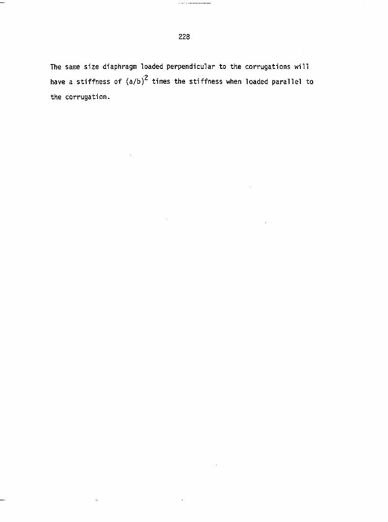
228
The same size diaphragm loaded perpendicular to the corrugations will
have a stiffness of (a/b) times the stiffness when loaded parallel to
the corrugation.
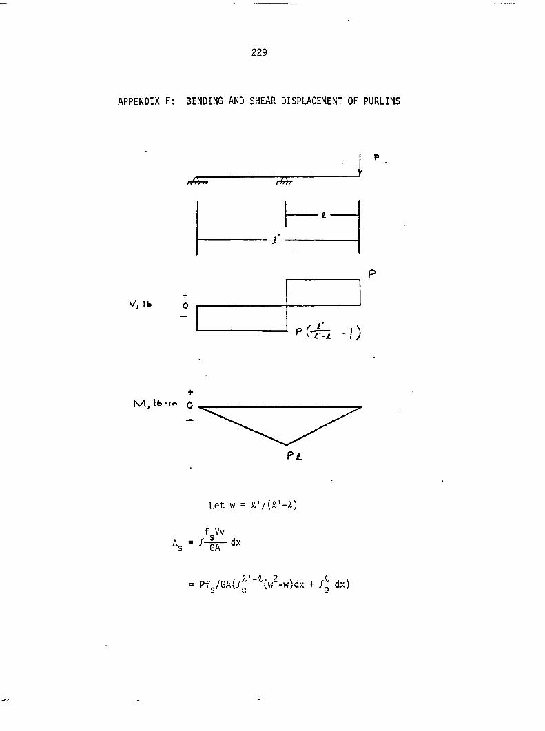
229
APPENDIX F: BENDING AND SHEAR DISPLACEMENT OF PURLINS
y/A n
V , l b + 0
-I)
N/lj Ib-to ^
Let w = &'/(&'-&)
f-Vv
= Pf^/GA(/J:'"'-{w^-w)dx + /J dx)
230
= - IV + Ji')/6A .
For Hp purlins:
Ag = Pfg((&'2/&'-A) - &')/GAnp
Afa = |j x^dx + /J x^dx)
= P&'A^/SEI .
For rip purlins:
Ay = P&'&2/3npEI
Ay = Pfc(A'2/A'.&) _ S,')/GAnp + P&'&2/3npEI .
231
APPENDIX G: DISPLACEMENT DUE TO PURLIN TWIST
1 . 1 9
i = / . S O F u
T
K - O . 5 0 0 P
1 0.440"
T
3.50
0.2 SO"
Assume the purlin pivots at edge A on rafter:
= 0 = 3.06F - 2-31(1.5F) - .35(.5F) + T
= 3.233 F - 3.465 F + T
T = .23 F
e = TL/JG (Higdon ^ , 1957)
J = I^ + ly = 21.4375 + 3.9375 = 25.38 in^
6 = E/16
232
Assume L is the width of the diaphragm:
e = 3.68 Fw/E(I^ + ly) .
The displacement is for one purlin:
A = 3.5 0
= 12.88F a/E(Ix + 1^)
= 12.88 a/E(Ix + 1^) .
For n purlin: P
A = 12.88 a/EHpd^ + ly)