Embed Size (px)
Citation preview
LIFE CYCLE MANAGEMENT SOLUTIONS Proprietary & Confidential Copyright © 2016 Kinectrics Inc. All rights reserved. Page 1
GENERATING SUCCESS FOR OVER 100 YEARS
Evaluation of Ground Grid
Performance: Testing and
Maintenance
Ehsan Azordegan, June 2017

LIFE CYCLE MANAGEMENT SOLUTIONS Proprietary & Confidential Copyright © 2016 Kinectrics Inc. All rights reserved. Page 2
Outline • Ground Grid Components • Ground Grid Modelling/Design • Basic Shock Situations (Step and Touch) • Tolerable Body Limit • Ground Grid Under Fault Conditions • Zero Sequence Analysis • Evaluating the Grid Performance
– Current Injection Test • Soil Resistivity Testing • Ground Grid Resistance • Current Injection Testing • Step and Touch Potentials
– Integrity Tests
LIFE CYCLE MANAGEMENT SOLUTIONS Proprietary & Confidential Copyright © 2016 Kinectrics Inc. All rights reserved. Page 3
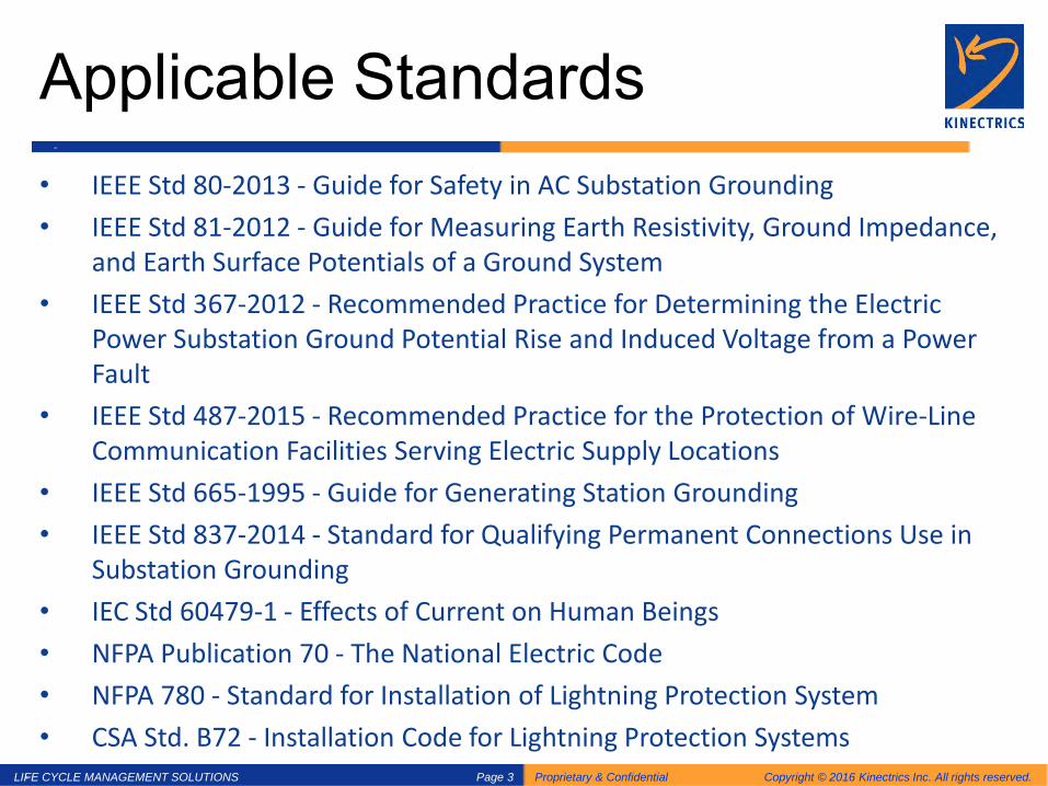
Applicable Standards • IEEE Std 80-2013 - Guide for Safety in AC Substation Grounding • IEEE Std 81-2012 - Guide for Measuring Earth Resistivity, Ground Impedance,
and Earth Surface Potentials of a Ground System • IEEE Std 367-2012 - Recommended Practice for Determining the Electric
Power Substation Ground Potential Rise and Induced Voltage from a Power Fault
• IEEE Std 487-2015 - Recommended Practice for the Protection of Wire-Line Communication Facilities Serving Electric Supply Locations
• IEEE Std 665-1995 - Guide for Generating Station Grounding • IEEE Std 837-2014 - Standard for Qualifying Permanent Connections Use in
Substation Grounding • IEC Std 60479-1 - Effects of Current on Human Beings • NFPA Publication 70 - The National Electric Code • NFPA 780 - Standard for Installation of Lightning Protection System • CSA Std. B72 - Installation Code for Lightning Protection Systems

LIFE CYCLE MANAGEMENT SOLUTIONS Proprietary & Confidential Copyright © 2016 Kinectrics Inc. All rights reserved. Page 4
Terminology
• Bonding: To provide a permanent low impedance path, with adequate current rating and redundancy, between an object and the ground grid.
• Grounding: To provide a permanent low
impedance path, with adequate current rating, between objects and remote earth.

LIFE CYCLE MANAGEMENT SOLUTIONS Proprietary & Confidential Copyright © 2016 Kinectrics Inc. All rights reserved. Page 5
Terminology • Ground Electrode: Buried conductors that
dissipate ground current into the earth. • Grounding System: All conductors that
facilitate grounding. • Ground Fault: An insulation failure between
an energized phase conductor and the grounding system.

LIFE CYCLE MANAGEMENT SOLUTIONS Proprietary & Confidential Copyright © 2016 Kinectrics Inc. All rights reserved. Page 6
Terminology • Ground Current: The current that enters a
grounding system. • Ground Potential Rise (GPR): The voltage
between a grounding system and remote earth during a ground fault.
• Remote Earth: A potential reference point sufficiently distant from the fault to experience negligible potential rise.
LIFE CYCLE MANAGEMENT SOLUTIONS Proprietary & Confidential Copyright © 2016 Kinectrics Inc. All rights reserved. Page 7
Terminology • Step Potential: The open circuit foot-to-foot
voltage during a ground fault. • Touch Potential: The open circuit hand-to-foot
voltage during a ground fault. • Mesh potential: The maximum touch voltage
experienced while standing within a mesh of a ground grid and touching a grounding object.
• Transferred Potential: The voltage between local soil and a grounded object that extends exterior to a station.

LIFE CYCLE MANAGEMENT SOLUTIONS Proprietary & Confidential Copyright © 2016 Kinectrics Inc. All rights reserved. Page 8
Grounding System Components
• Ground Grid: A meshed system of buried conductors used to provide contact with the underlying earth.
• Ground Rods: Ground rods are vertical rods used to facilitate the conduction of fault current from the ground grid to the deeper soil layer in the underlying earth

LIFE CYCLE MANAGEMENT SOLUTIONS Proprietary & Confidential Copyright © 2016 Kinectrics Inc. All rights reserved. Page 9
Grounding System Components
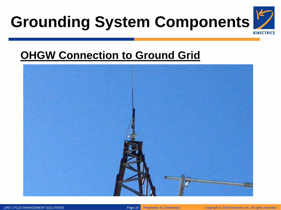
Overhead Ground Wires: Ground conductors located above phase conductors on transmission lines used to shield the overhead high voltage conductors from lightning strikes.
LIFE CYCLE MANAGEMENT SOLUTIONS Proprietary & Confidential Copyright © 2016 Kinectrics Inc. All rights reserved. Page 10
Grounding System Components
OHGW Connection to Ground Grid

LIFE CYCLE MANAGEMENT SOLUTIONS Proprietary & Confidential Copyright © 2016 Kinectrics Inc. All rights reserved. Page 11
Distribution/Concentric Neutral

LIFE CYCLE MANAGEMENT SOLUTIONS Proprietary & Confidential Copyright © 2016 Kinectrics Inc. All rights reserved. Page 12
Objectives of Grounding Primary objectives of grounding are to:
1. Protect life from the danger of electric shocks by limiting potential differences between touchable objects during normal or fault conditions
2. Isolate faults as soon as possible by providing a low impedance path to ground in order to activate protection
3. Redirect fault current and lightning away from equipment and property susceptible to damage
4. Minimize electrical interference
LIFE CYCLE MANAGEMENT SOLUTIONS Proprietary & Confidential Copyright © 2016 Kinectrics Inc. All rights reserved. Page 13
Calculating Ground Grid Parameters: Simplified Scenarios
• See how simple grounding formulas are derived • Understanding the concept of remote earth resistance • Relation between resistance and soil resistivity • Show how image methods handle multilayer soil

LIFE CYCLE MANAGEMENT SOLUTIONS Proprietary & Confidential Copyright © 2016 Kinectrics Inc. All rights reserved. Page 14
Why Modelling is Important?
• Analytical understanding • Predicts performance before construction • Allows optimizing use of copper • Usually less expensive than testing • Many different modelling tools available • Results can easily be rechecked

LIFE CYCLE MANAGEMENT SOLUTIONS Proprietary & Confidential Copyright © 2016 Kinectrics Inc. All rights reserved. Page 15
Mutual Resistance Rm(x), Half Sphere Rg
2r2
Ig)r(Jπ
=
)r(J)r(E ρ=
∫= dr)r(E)x(V
Resistivity ρ
∞
π
ρ=
xr2Ig
x2Igπ
ρ=
a2Rg
x2)x(RmMutual
πρ
=πρ
=
Ig V(a) x V(x) a

LIFE CYCLE MANAGEMENT SOLUTIONS Proprietary & Confidential Copyright © 2016 Kinectrics Inc. All rights reserved. Page 16
Sunde (1949) Ellipsoids of Revolution
a
d
a a
a4RgDisk ρ
=ad2ln
d2RgRod
πρ
=a2
RgSphereπρ
=
E.D. Sunde, “Earth Conduction Effects of Transmission Systems”, Van Nostrand, 1949, p 71

LIFE CYCLE MANAGEMENT SOLUTIONS Proprietary & Confidential Copyright © 2016 Kinectrics Inc. All rights reserved. Page 17
Two Layer Soil Gives Multiple Images
I k I
k2 I k I
k I k2 I
k I I
P
1212
ρρρρK
+−
=
ρ1
ρ2
( )∑
+πρ
+πρ
=∞
=1 2211
22 n
n
hnx
Kx
)x(Rm
h

LIFE CYCLE MANAGEMENT SOLUTIONS Proprietary & Confidential Copyright © 2016 Kinectrics Inc. All rights reserved. Page 18
Importance of Soil Information
• The grid resistance if directly proportional to soil resistivity.
• Similar grid arrangements in different soils have completely different performances
a4RgDisk ρ
=

LIFE CYCLE MANAGEMENT SOLUTIONS Proprietary & Confidential Copyright © 2016 Kinectrics Inc. All rights reserved. Page 19
Grounding Perspectives • Concept of Remote Electrode, Earth Resistance
• Integrity, Bonding, 4 point resistance measurement
Ig V(a)
x V(x)
a
LIFE CYCLE MANAGEMENT SOLUTIONS Proprietary & Confidential Copyright © 2016 Kinectrics Inc. All rights reserved. Page 20
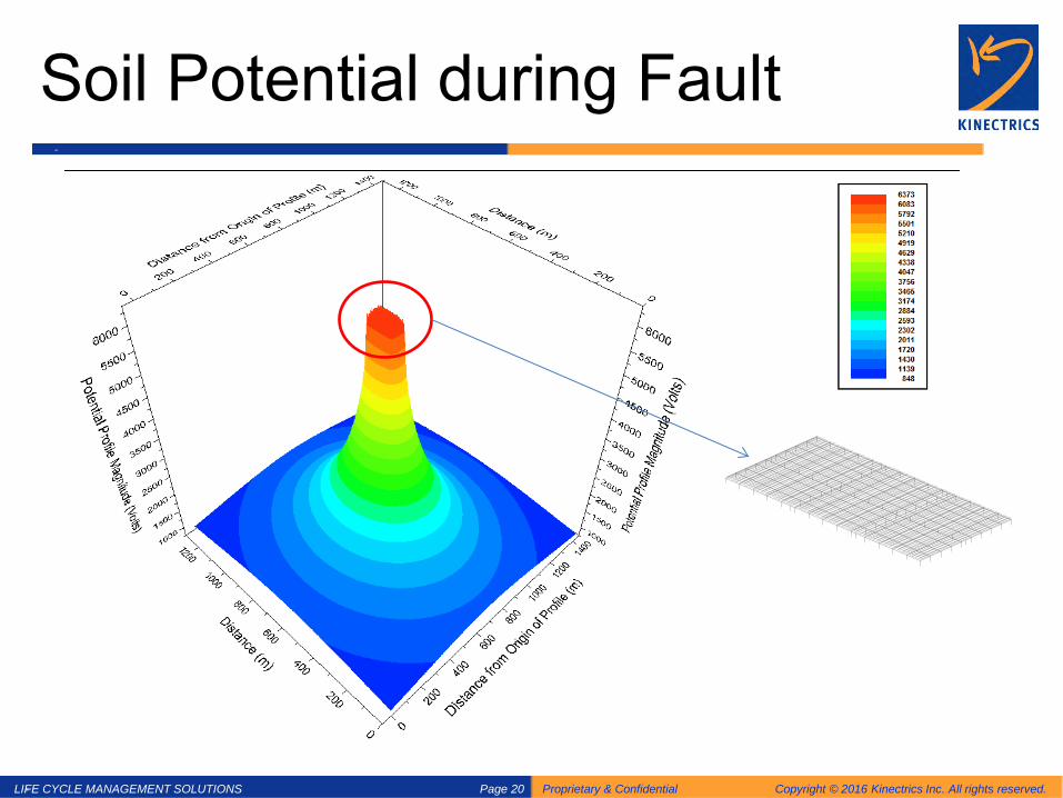
Soil Potential during Fault
LIFE CYCLE MANAGEMENT SOLUTIONS Proprietary & Confidential Copyright © 2016 Kinectrics Inc. All rights reserved. Page 21
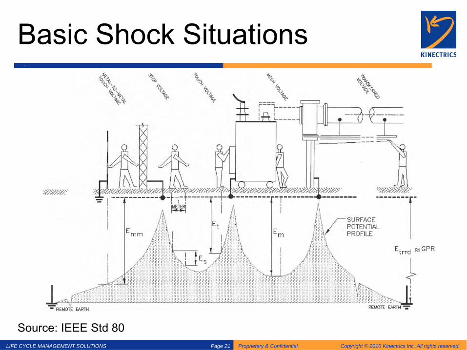
Basic Shock Situations
Source: IEEE Std 80

LIFE CYCLE MANAGEMENT SOLUTIONS Proprietary & Confidential Copyright © 2016 Kinectrics Inc. All rights reserved. Page 22
Touch Voltage Modelling
Source: IEEE Std 80

LIFE CYCLE MANAGEMENT SOLUTIONS Proprietary & Confidential Copyright © 2016 Kinectrics Inc. All rights reserved. Page 23
Open Circuit Touch Voltage
Source: IEEE Std 80
LIFE CYCLE MANAGEMENT SOLUTIONS Proprietary & Confidential Copyright © 2016 Kinectrics Inc. All rights reserved. Page 24
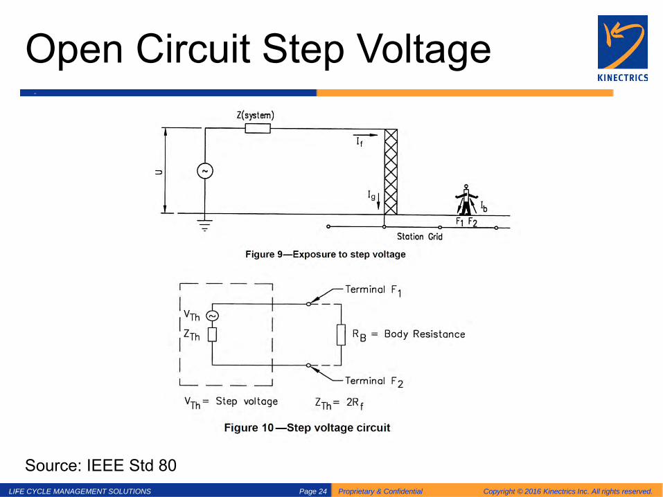
Open Circuit Step Voltage
Source: IEEE Std 80

LIFE CYCLE MANAGEMENT SOLUTIONS Proprietary & Confidential Copyright © 2016 Kinectrics Inc. All rights reserved. Page 25
Resistance of one foot
Model foot resistance by a disk with radius of 8 cm ( b=0.08 m)
𝑅𝑅𝑓𝑓 =𝜌𝜌
4 × 0.08≅ 3𝜌𝜌
𝑅𝑅𝑓𝑓 =𝜌𝜌
4 × 𝑏𝑏
𝑍𝑍𝑡𝑡𝑡 = 1.5 × 𝜌𝜌
𝑍𝑍𝑡𝑡𝑡 = 6 × 𝜌𝜌
For Touch
For Step

LIFE CYCLE MANAGEMENT SOLUTIONS Proprietary & Confidential Copyright © 2016 Kinectrics Inc. All rights reserved. Page 26
Maximum Voltage Threshold
• 𝑉𝑉𝑇𝑇𝑡𝑇𝑇𝑇𝑇𝑇𝑇𝑡𝑇𝑇𝑇𝑇𝑇𝑇 = (𝑅𝑅𝐵𝐵𝑇𝑇𝑇𝑇𝐵𝐵 + 𝑍𝑍𝑡𝑡𝑡) × 𝐼𝐼𝑚𝑚𝑚𝑚𝑚𝑚
𝑅𝑅𝐵𝐵𝑇𝑇𝑇𝑇𝐵𝐵 (Body Resistance)
𝐼𝐼𝑚𝑚𝑚𝑚𝑚𝑚 (Electrocution Current)

LIFE CYCLE MANAGEMENT SOLUTIONS Proprietary & Confidential Copyright © 2016 Kinectrics Inc. All rights reserved. Page 27
Body Impedance Model - Einthoven
100 V
LIFE CYCLE MANAGEMENT SOLUTIONS Proprietary & Confidential Copyright © 2016 Kinectrics Inc. All rights reserved. Page 28
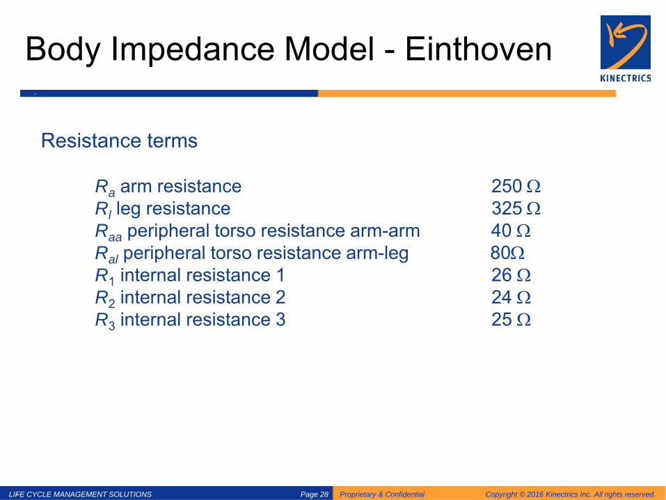
Body Impedance Model - Einthoven
Resistance terms Ra arm resistance 250 Ω Rl leg resistance 325 Ω Raa peripheral torso resistance arm-arm 40 Ω Ral peripheral torso resistance arm-leg 80Ω R1 internal resistance 1 26 Ω R2 internal resistance 2 24 Ω R3 internal resistance 3 25 Ω
LIFE CYCLE MANAGEMENT SOLUTIONS Proprietary & Confidential Copyright © 2016 Kinectrics Inc. All rights reserved. Page 29
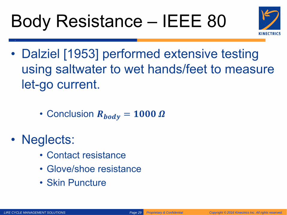
Body Resistance – IEEE 80
• Dalziel [1953] performed extensive testing using saltwater to wet hands/feet to measure let-go current.
• Conclusion 𝑹𝑹𝒃𝒃𝒃𝒃𝒃𝒃𝒃𝒃 = 𝟏𝟏𝟏𝟏𝟏𝟏𝟏𝟏 𝜴𝜴
• Neglects: • Contact resistance • Glove/shoe resistance • Skin Puncture

LIFE CYCLE MANAGEMENT SOLUTIONS Proprietary & Confidential Copyright © 2016 Kinectrics Inc. All rights reserved. Page 30
Electrocution Current: IEC 60749 to IEEE 80 30
LIFE CYCLE MANAGEMENT SOLUTIONS Proprietary & Confidential Copyright © 2016 Kinectrics Inc. All rights reserved. Page 31
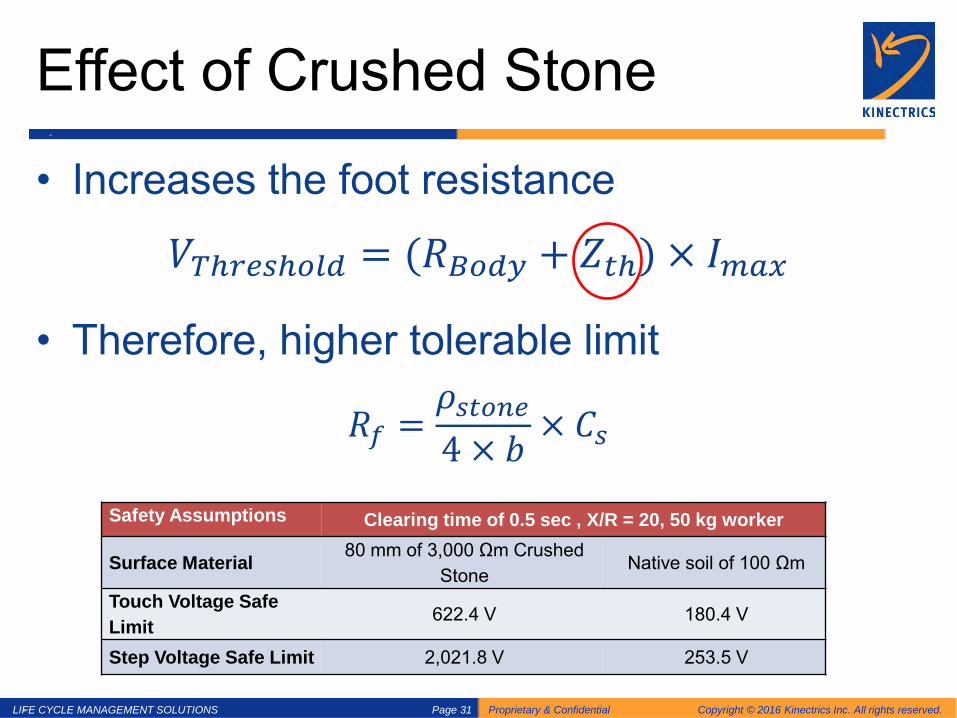
Effect of Crushed Stone
• Increases the foot resistance
𝑉𝑉𝑇𝑇𝑡𝑇𝑇𝑇𝑇𝑇𝑇𝑡𝑇𝑇𝑇𝑇𝑇𝑇 = (𝑅𝑅𝐵𝐵𝑇𝑇𝑇𝑇𝐵𝐵 + 𝑍𝑍𝑡𝑡𝑡) × 𝐼𝐼𝑚𝑚𝑚𝑚𝑚𝑚
• Therefore, higher tolerable limit
𝑅𝑅𝑓𝑓 =𝜌𝜌𝑇𝑇𝑡𝑡𝑇𝑇𝑠𝑠𝑇𝑇4 × 𝑏𝑏
× 𝐶𝐶𝑇𝑇
Safety Assumptions Clearing time of 0.5 sec , X/R = 20, 50 kg worker
Surface Material 80 mm of 3,000 Ωm Crushed Stone
Native soil of 100 Ωm
Touch Voltage Safe Limit 622.4 V 180.4 V
Step Voltage Safe Limit 2,021.8 V 253.5 V

LIFE CYCLE MANAGEMENT SOLUTIONS Proprietary & Confidential Copyright © 2016 Kinectrics Inc. All rights reserved. Page 32
Ground Grid Under Fault Conditions

LIFE CYCLE MANAGEMENT SOLUTIONS Proprietary & Confidential Copyright © 2016 Kinectrics Inc. All rights reserved. Page 33
Fault Current From Remote Source
If
Ig = If - In - Ii Ie = Ig - Id – 2 Ic
Ie
Id
In
Ii + Ic Ic

LIFE CYCLE MANAGEMENT SOLUTIONS Proprietary & Confidential Copyright © 2016 Kinectrics Inc. All rights reserved. Page 34
Simplified Scenario

LIFE CYCLE MANAGEMENT SOLUTIONS Proprietary & Confidential Copyright © 2016 Kinectrics Inc. All rights reserved. Page 35
Problem Formulation

LIFE CYCLE MANAGEMENT SOLUTIONS Proprietary & Confidential Copyright © 2016 Kinectrics Inc. All rights reserved. Page 36
Split Factor
LIFE CYCLE MANAGEMENT SOLUTIONS Proprietary & Confidential Copyright © 2016 Kinectrics Inc. All rights reserved. Page 37
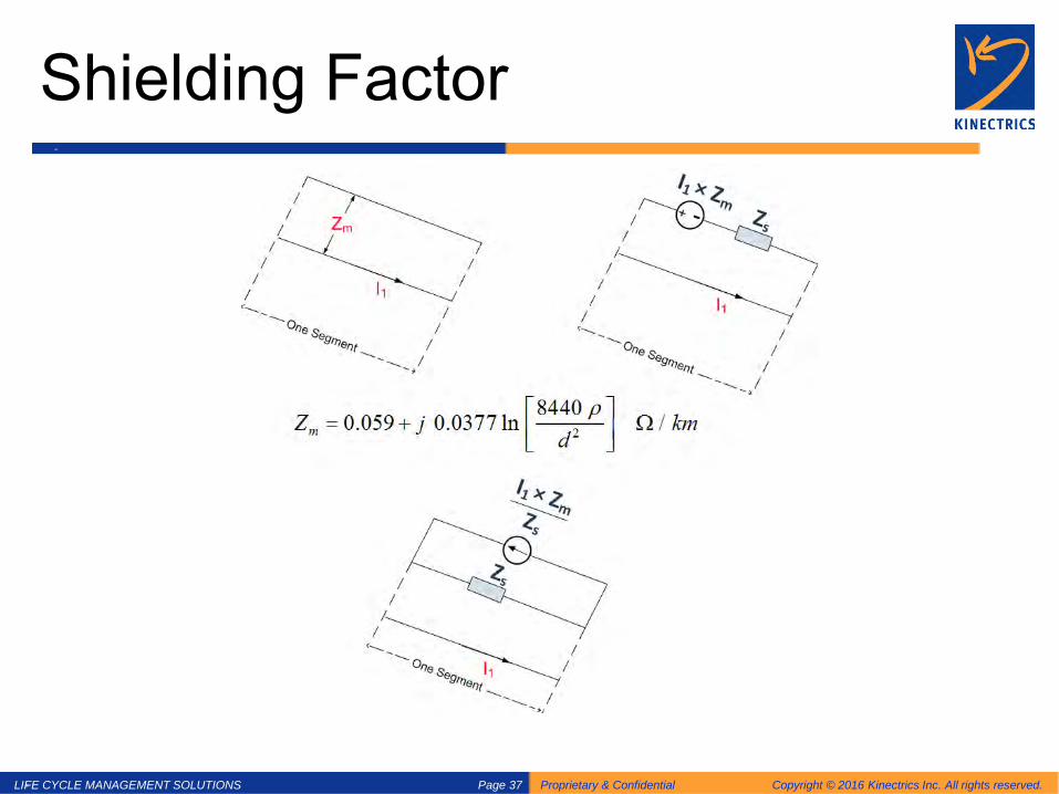
Shielding Factor
LIFE CYCLE MANAGEMENT SOLUTIONS Proprietary & Confidential Copyright © 2016 Kinectrics Inc. All rights reserved. Page 38
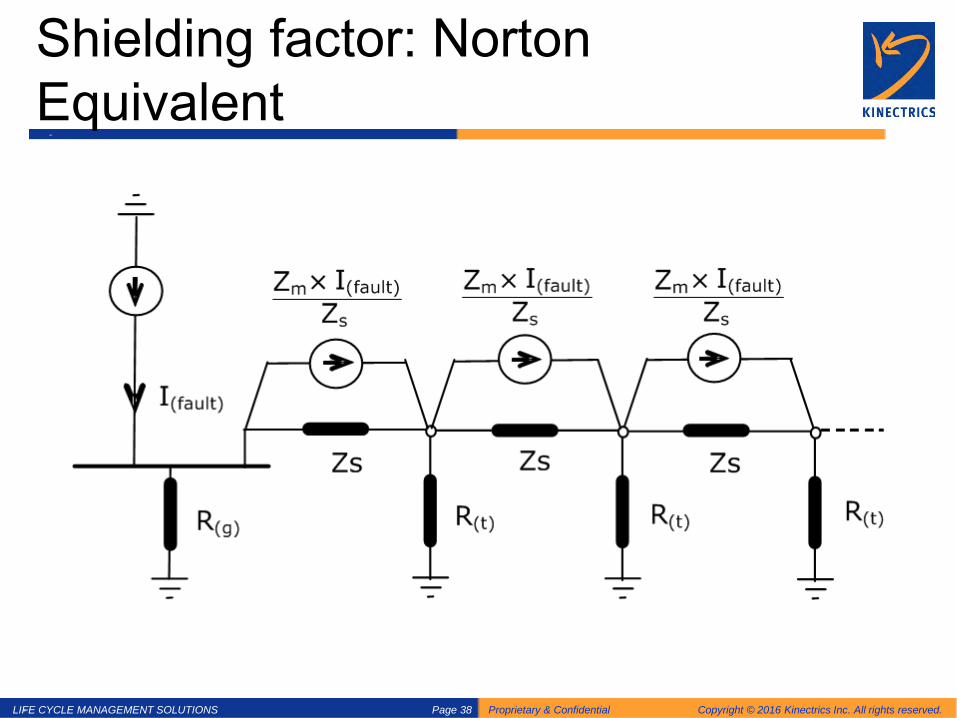
Shielding factor: Norton Equivalent

LIFE CYCLE MANAGEMENT SOLUTIONS Proprietary & Confidential Copyright © 2016 Kinectrics Inc. All rights reserved. Page 39
Shielding factor: De-coupled

LIFE CYCLE MANAGEMENT SOLUTIONS Proprietary & Confidential Copyright © 2016 Kinectrics Inc. All rights reserved. Page 40
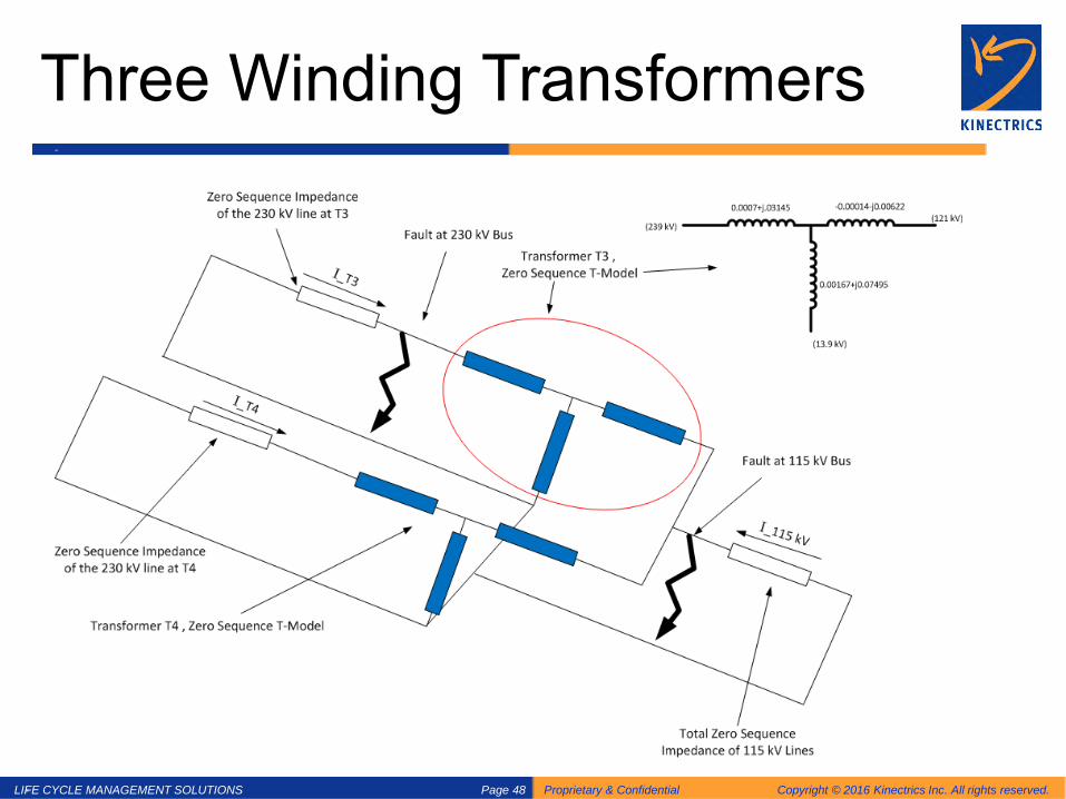
Circulating Current within the Transformer
• Some of the fault current will be circulating within the transformer
• The circulating current will not return to remote earth and therefore will not cause any GPR
• To properly account for the circulating current, transformer winding configuration as well as the impedance model must be known

LIFE CYCLE MANAGEMENT SOLUTIONS Proprietary & Confidential Copyright © 2016 Kinectrics Inc. All rights reserved. Page 41
Sequence Network Theory
(Fortescue's Theorem 1918) Three unbalanced phasors of a three phase system can be mapped into three balanced systems of phasors. The balanced sets of components are: • Positive sequence components: consisting of three phasors
equal in magnitude, 120o apart in phase, but have the same phase sequence as the original phasors.
• Negative sequence components: consisting of three phasors equal in magnitude, 120o apart in phase, and have the opposite phase sequence as the original phasors.
• Zero sequence components: consisting of three phasors equal in magnitude and with zero phase displacement from each other.

LIFE CYCLE MANAGEMENT SOLUTIONS Proprietary & Confidential Copyright © 2016 Kinectrics Inc. All rights reserved. Page 42
Sequence Network Theory
LIFE CYCLE MANAGEMENT SOLUTIONS Proprietary & Confidential Copyright © 2016 Kinectrics Inc. All rights reserved. Page 43
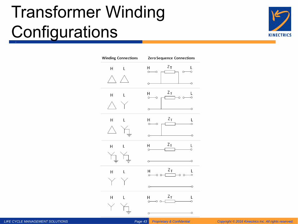
Transformer Winding Configurations
LIFE CYCLE MANAGEMENT SOLUTIONS Proprietary & Confidential Copyright © 2016 Kinectrics Inc. All rights reserved. Page 44
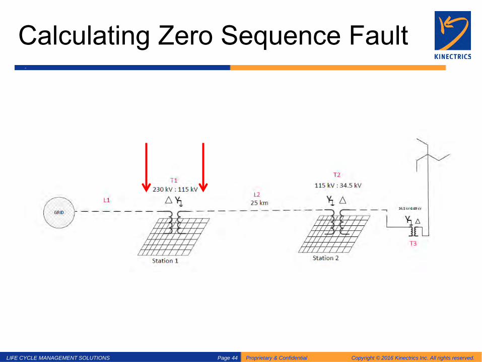
Calculating Zero Sequence Fault
LIFE CYCLE MANAGEMENT SOLUTIONS Proprietary & Confidential Copyright © 2016 Kinectrics Inc. All rights reserved. Page 45
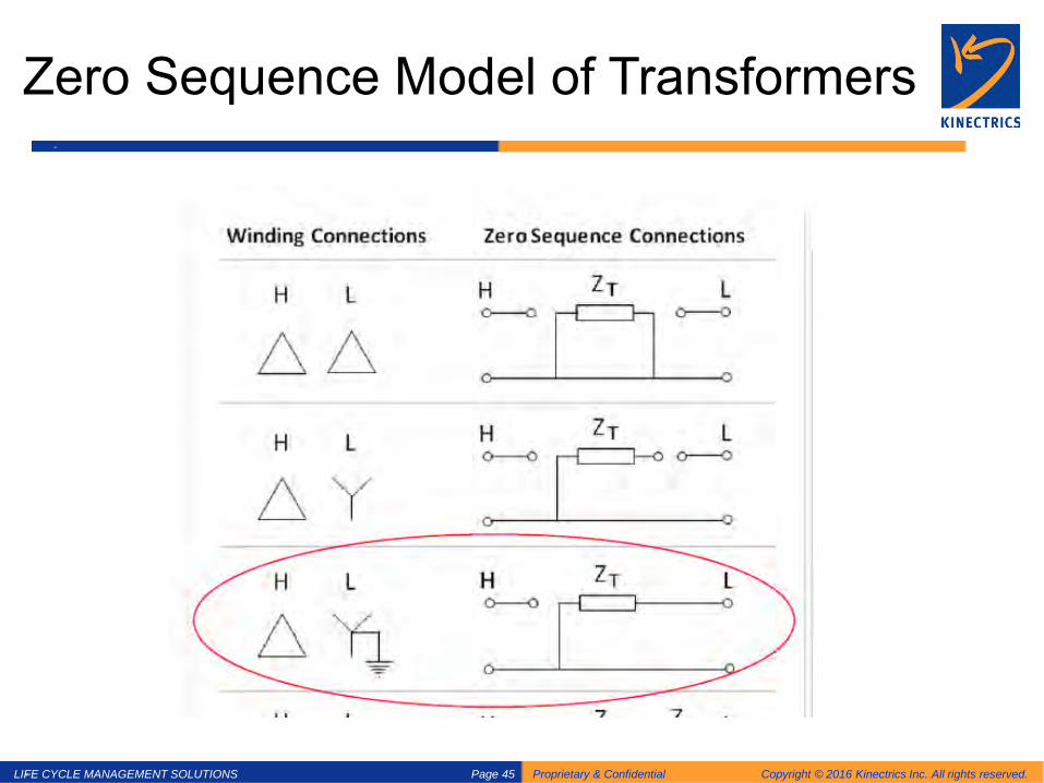
Zero Sequence Model of Transformers
LIFE CYCLE MANAGEMENT SOLUTIONS Proprietary & Confidential Copyright © 2016 Kinectrics Inc. All rights reserved. Page 46
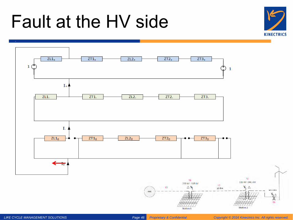
Fault at the HV side

LIFE CYCLE MANAGEMENT SOLUTIONS Proprietary & Confidential Copyright © 2016 Kinectrics Inc. All rights reserved. Page 47
Fault at LV Side
LIFE CYCLE MANAGEMENT SOLUTIONS Proprietary & Confidential Copyright © 2016 Kinectrics Inc. All rights reserved. Page 48
Three Winding Transformers

LIFE CYCLE MANAGEMENT SOLUTIONS Proprietary & Confidential Copyright © 2016 Kinectrics Inc. All rights reserved. Page 49
Summary – Fault Analysis

LIFE CYCLE MANAGEMENT SOLUTIONS Proprietary & Confidential Copyright © 2016 Kinectrics Inc. All rights reserved. Page 50
Problem Formulation

LIFE CYCLE MANAGEMENT SOLUTIONS Proprietary & Confidential Copyright © 2016 Kinectrics Inc. All rights reserved. Page 51
Driving Point Impedance - Decoupling
LIFE CYCLE MANAGEMENT SOLUTIONS Proprietary & Confidential Copyright © 2016 Kinectrics Inc. All rights reserved. Page 52
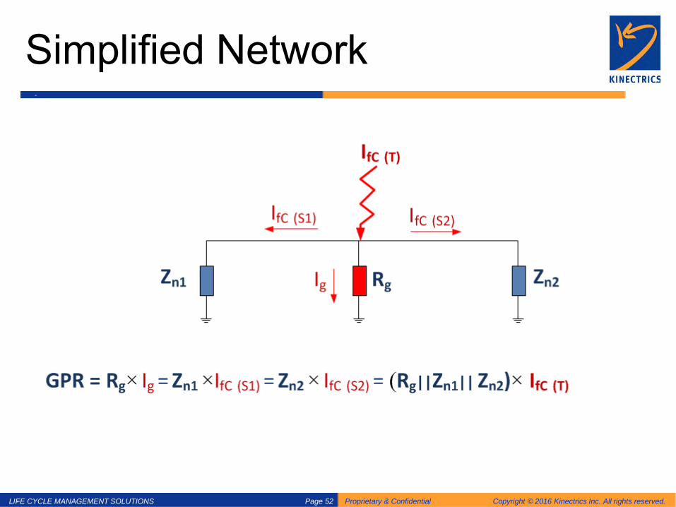
Simplified Network

LIFE CYCLE MANAGEMENT SOLUTIONS Proprietary & Confidential Copyright © 2016 Kinectrics Inc. All rights reserved. Page 53
Transformer Circulating Current

LIFE CYCLE MANAGEMENT SOLUTIONS Proprietary & Confidential Copyright © 2016 Kinectrics Inc. All rights reserved. Page 54
Zone of Influence
• IEEE Std. 367 • 300 V peak contour • Affected telephone communication pedestals
– Twisted pairs – Pedestal ground is ok…
IEEE 367 - Recommended Practice for Determining the Electric Power Station Ground Potential Rise and Induced Voltage from a Power Fault

LIFE CYCLE MANAGEMENT SOLUTIONS Proprietary & Confidential Copyright © 2016 Kinectrics Inc. All rights reserved. Page 55
Zone of Influence
0
500
1000
1500
2000
2500
3000
3500
4000
4500
0 100 200 300 400 500 600 700 800 900 1000
Soil
Pote
ntia
l
Distance from Grid Center (m)
𝑽𝑽𝒙𝒙 =𝝆𝝆𝟐𝟐𝝅𝝅𝒙𝒙
𝑰𝑰

LIFE CYCLE MANAGEMENT SOLUTIONS Proprietary & Confidential Copyright © 2016 Kinectrics Inc. All rights reserved. Page 56
Evaluating the Grounding System Performance
• Two Aspects:
When a fault happens, what is the potential rise of the grounding system (GPR) and will it be safe to touch grounded equipment (touch potential) or walk within the yard (step potential)? Are all equipment/structures properly tied to the grid with fault rated ground conductors?
Integrity Tests
Current Injection Tests (Fall of Potential)
LIFE CYCLE MANAGEMENT SOLUTIONS Proprietary & Confidential Copyright © 2016 Kinectrics Inc. All rights reserved. Page 57
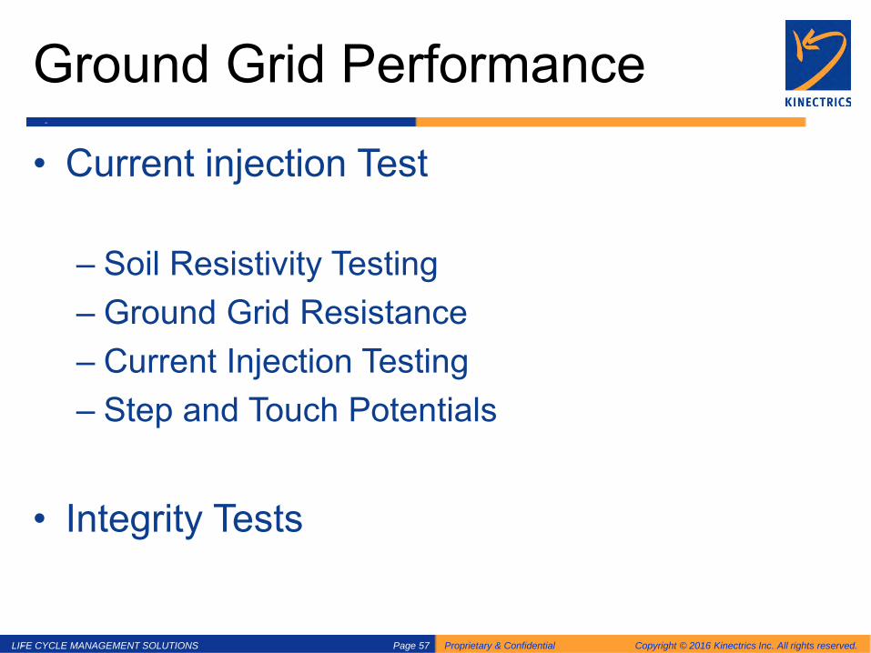
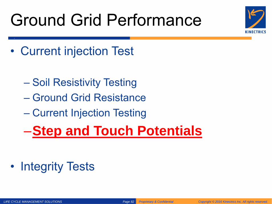
Ground Grid Performance
• Current injection Test
– Soil Resistivity Testing – Ground Grid Resistance – Current Injection Testing – Step and Touch Potentials
• Integrity Tests

LIFE CYCLE MANAGEMENT SOLUTIONS Proprietary & Confidential Copyright © 2016 Kinectrics Inc. All rights reserved. Page 58
Ground Grid Performance
• Current Injection Test
–Soil Resistivity Testing – Ground Grid Resistance – Current Injection Testing – Step and Touch Potentials
• Integrity Tests
LIFE CYCLE MANAGEMENT SOLUTIONS Proprietary & Confidential Copyright © 2016 Kinectrics Inc. All rights reserved. Page 59
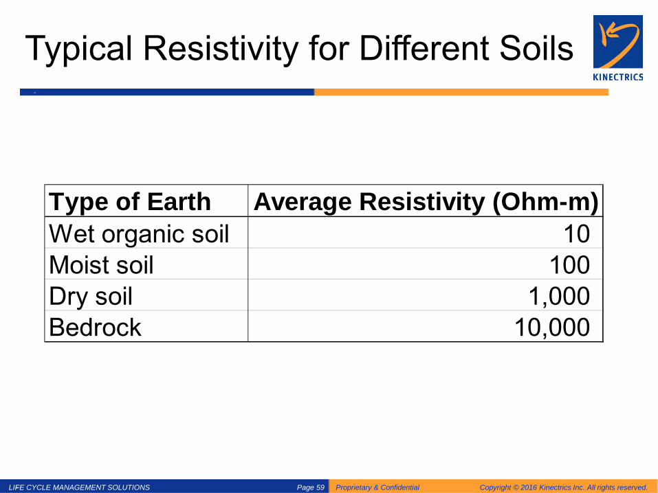
Typical Resistivity for Different Soils
Type of Earth Average Resistivity (Ohm-m)Wet organic soil 10 Moist soil 100 Dry soil 1,000 Bedrock 10,000

LIFE CYCLE MANAGEMENT SOLUTIONS Proprietary & Confidential Copyright © 2016 Kinectrics Inc. All rights reserved. Page 60
Measurement Techniques Wenner Survey Techniques Four equally spaced probes are driven into the soil.
s s s s s s
LIFE CYCLE MANAGEMENT SOLUTIONS Proprietary & Confidential Copyright © 2016 Kinectrics Inc. All rights reserved. Page 61
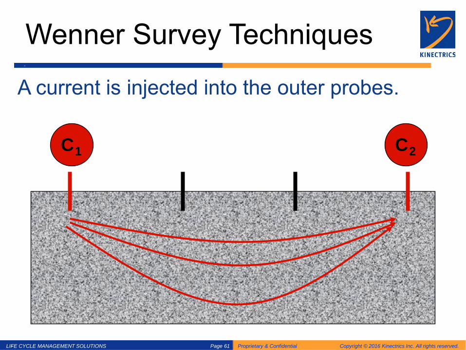
Wenner Survey Techniques
A current is injected into the outer probes.
s s s C1 C2

LIFE CYCLE MANAGEMENT SOLUTIONS Proprietary & Confidential Copyright © 2016 Kinectrics Inc. All rights reserved. Page 62
Wenner Survey Techniques
A voltage is measured at the inner probes.
s s s C1 P1 P2 C2

LIFE CYCLE MANAGEMENT SOLUTIONS Proprietary & Confidential Copyright © 2016 Kinectrics Inc. All rights reserved. Page 63
Wenner Survey Techniques •The apparent resistivity is calculated:
•lw is the probe depth •s is the Wenner probe spacing
2 2 2 2
421
4
a
w w
V ss sI
s l s l
πρ ∆=
+ −+ +
)(2)( sRss ma ⋅⋅⋅= πρfor lw << s
𝑅𝑅𝑚𝑚(𝑠𝑠)

LIFE CYCLE MANAGEMENT SOLUTIONS Proprietary & Confidential Copyright © 2016 Kinectrics Inc. All rights reserved. Page 64
Soil Resistivity Testing

LIFE CYCLE MANAGEMENT SOLUTIONS Proprietary & Confidential Copyright © 2016 Kinectrics Inc. All rights reserved. Page 65
Soil Resistivity Surveys
LIFE CYCLE MANAGEMENT SOLUTIONS Proprietary & Confidential Copyright © 2016 Kinectrics Inc. All rights reserved. Page 66
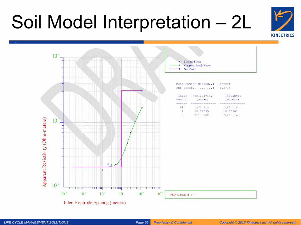
Soil Model Interpretation – 2L
LIFE CYCLE MANAGEMENT SOLUTIONS Proprietary & Confidential Copyright © 2016 Kinectrics Inc. All rights reserved. Page 67
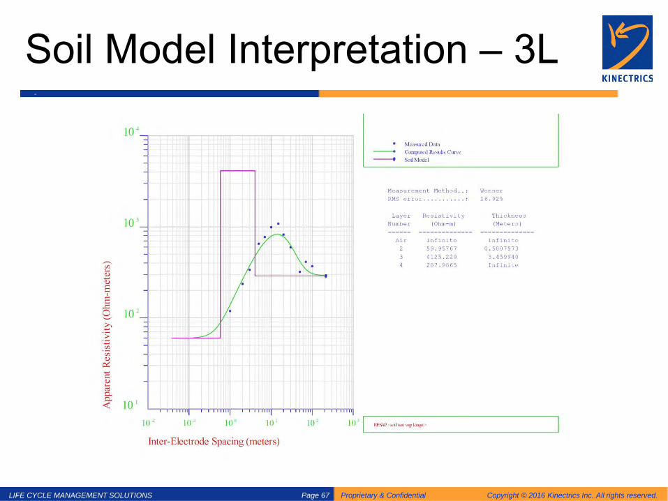
Soil Model Interpretation – 3L

LIFE CYCLE MANAGEMENT SOLUTIONS Proprietary & Confidential Copyright © 2016 Kinectrics Inc. All rights reserved. Page 68
Ground Grid Performance
• Current injection Test
– Soil Resistivity Testing
–Ground Grid Resistance – Current Injection Testing – Step and Touch Potentials
• Integrity Tests
LIFE CYCLE MANAGEMENT SOLUTIONS Proprietary & Confidential Copyright © 2016 Kinectrics Inc. All rights reserved. Page 69
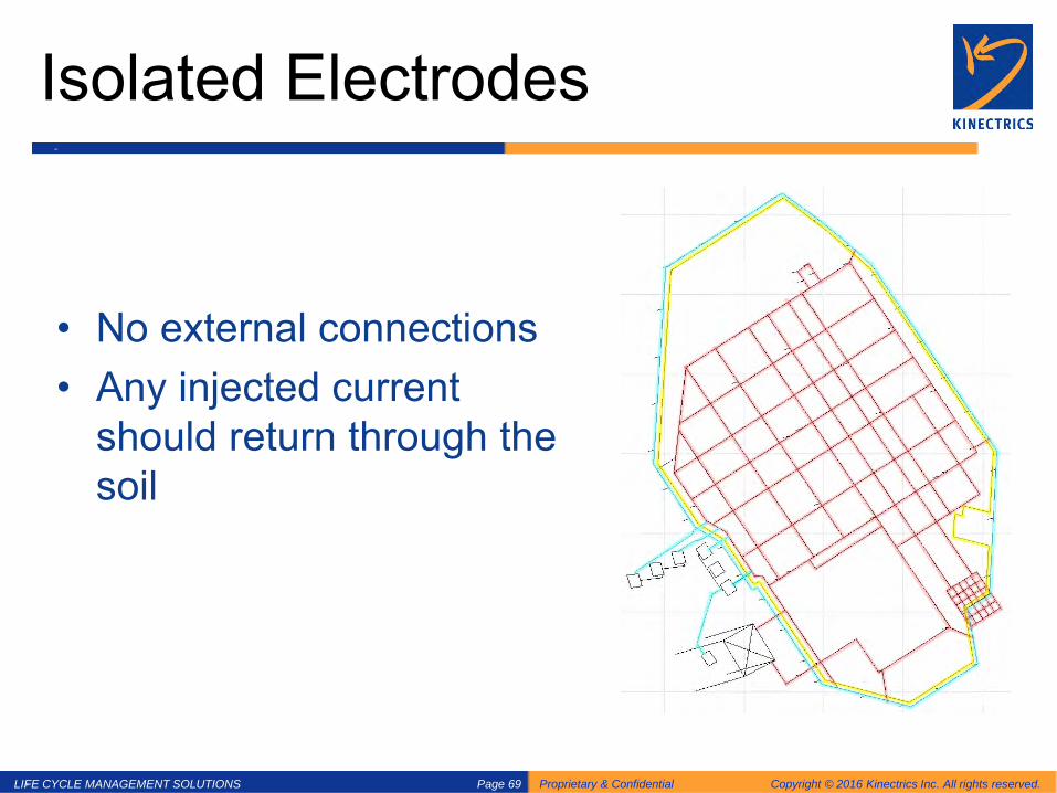
Isolated Electrodes
• No external connections • Any injected current
should return through the soil

LIFE CYCLE MANAGEMENT SOLUTIONS Proprietary & Confidential Copyright © 2016 Kinectrics Inc. All rights reserved. Page 70
Fall of Potential (FOP) or 3 Pin Method
IEEE Std 81-2012
• Widely accepted method • Isolated grid only • Test current - 50 Hz to 3400 Hz • Reference electrodes E and G • P usually in the same direction as EG • How far should EG be?
E P G

LIFE CYCLE MANAGEMENT SOLUTIONS Proprietary & Confidential Copyright © 2016 Kinectrics Inc. All rights reserved. Page 71
Deriving the 62% formula

LIFE CYCLE MANAGEMENT SOLUTIONS Proprietary & Confidential Copyright © 2016 Kinectrics Inc. All rights reserved. Page 72
Variations of 3-Pin FOP
LIFE CYCLE MANAGEMENT SOLUTIONS Proprietary & Confidential Copyright © 2016 Kinectrics Inc. All rights reserved. Page 73
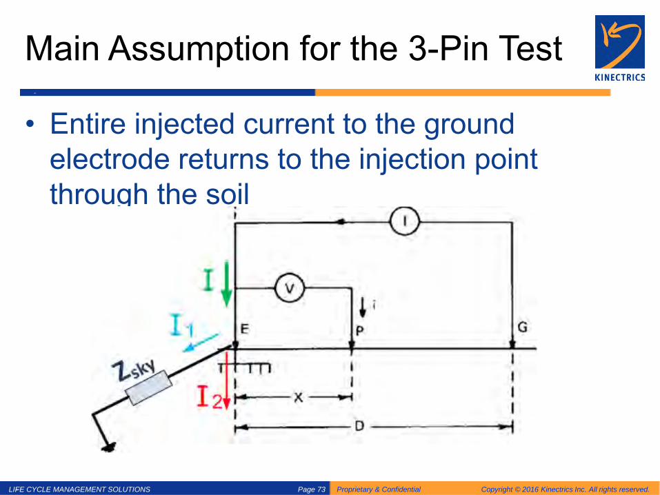
Main Assumption for the 3-Pin Test
• Entire injected current to the ground electrode returns to the injection point through the soil

LIFE CYCLE MANAGEMENT SOLUTIONS Proprietary & Confidential Copyright © 2016 Kinectrics Inc. All rights reserved. Page 74
Drawbacks with the 3- Pin Test
– Not intended for grids with interconnections – Can’t measure Step and Touch voltages – Can’t measure Current Splits into external
connection – Phase angle information not recorded
Solution? – Current Injection Testing – Customized off-frequency current injection – Recording soil potential profiles (complex) – Measuring Current Splits – Measuring Step and Touch

LIFE CYCLE MANAGEMENT SOLUTIONS Proprietary & Confidential Copyright © 2016 Kinectrics Inc. All rights reserved. Page 75
Ground Grid Performance
• Current injection Test
– Soil Resistivity Testing – Ground Grid Resistance
–Current Injection Testing – Step and Touch Potentials
• Integrity Tests

LIFE CYCLE MANAGEMENT SOLUTIONS Proprietary & Confidential Copyright © 2016 Kinectrics Inc. All rights reserved. Page 76
Overland Current Injection Testing
pg
cg P2
C2
grid
Vm - +
Im
θ
cp

LIFE CYCLE MANAGEMENT SOLUTIONS Proprietary & Confidential Copyright © 2016 Kinectrics Inc. All rights reserved. Page 77
Proximity Correction
cg pg
cp
I
- Vcg +
α Im + Vpg - - Vcp +
+ Vm -
Ze
Rg
C2 P2
)cp(Rm)pg(RmRgZe
Ze)cg(RmZtZg −α+
++=
Solving for Zg needs soil resistivity info, current split test and modelling of Rg

LIFE CYCLE MANAGEMENT SOLUTIONS Proprietary & Confidential Copyright © 2016 Kinectrics Inc. All rights reserved. Page 78
Test Set up…

LIFE CYCLE MANAGEMENT SOLUTIONS Proprietary & Confidential Copyright © 2016 Kinectrics Inc. All rights reserved. Page 79
Current Injection Test Set up
• Off-frequency Signal Generator • 4 channel signal analyser • Signal post-processing
Protection Box Amplifier Post
Processing

LIFE CYCLE MANAGEMENT SOLUTIONS Proprietary & Confidential Copyright © 2016 Kinectrics Inc. All rights reserved. Page 80
Source: Kinectrics Inc.
How to correct for proximity?

LIFE CYCLE MANAGEMENT SOLUTIONS Proprietary & Confidential Copyright © 2016 Kinectrics Inc. All rights reserved. Page 81
# Distance From P to G
Measured Impedance Readings Modelled Impedance Readings
Abs Ph Complex Abs Ph Complex
1 330 (m) 0.0619 53.9 0.0365+0.0500i 0.0769 35.9 0.0623+0.0451i 2 530 (m) 0.0783 43.6 0.0567+0.0540i 0.0862 36.2 0.0696+0.0509i 3 735 (m) 0.0825 42.1 0.0612+0.0553i 0.0884 37.9 0.0698+0.0543i 4 885 (m) 0.0842 40.5 0.0640+0.0547i 0.0883 39.5 0.0683+0.0561i 5 1,085 (m) 0.0855 38.1 0.0673+0.0528i 0.0875 41.6 0.0656+0.0580i 6 1,260 (m) 0.0857 39.6 0.0660+0.0546i 0.0865 43.6 0.0627+0.0596i 7 1,430 (m) 0.0861 35.0 0.0705+0.0494i 0.0859 45.0 0.0609+0.0607i
RMSE (Magnitudes) – Model vs. Measured 8.2%
Source: Kinectrics Inc.
Proximity Correction
LIFE CYCLE MANAGEMENT SOLUTIONS Proprietary & Confidential Copyright © 2016 Kinectrics Inc. All rights reserved. Page 82
Ground Grid Performance
• Current injection Test
– Soil Resistivity Testing – Ground Grid Resistance – Current Injection Testing
–Step and Touch Potentials
• Integrity Tests

LIFE CYCLE MANAGEMENT SOLUTIONS Proprietary & Confidential Copyright © 2016 Kinectrics Inc. All rights reserved. Page 83
Step and Touch Potentials
Frequency Selective Voltmeter

LIFE CYCLE MANAGEMENT SOLUTIONS Proprietary & Confidential Copyright © 2016 Kinectrics Inc. All rights reserved. Page 84
Stone Tests

LIFE CYCLE MANAGEMENT SOLUTIONS Proprietary & Confidential Copyright © 2016 Kinectrics Inc. All rights reserved. Page 85
Current Splits
LIFE CYCLE MANAGEMENT SOLUTIONS Proprietary & Confidential Copyright © 2016 Kinectrics Inc. All rights reserved. Page 86
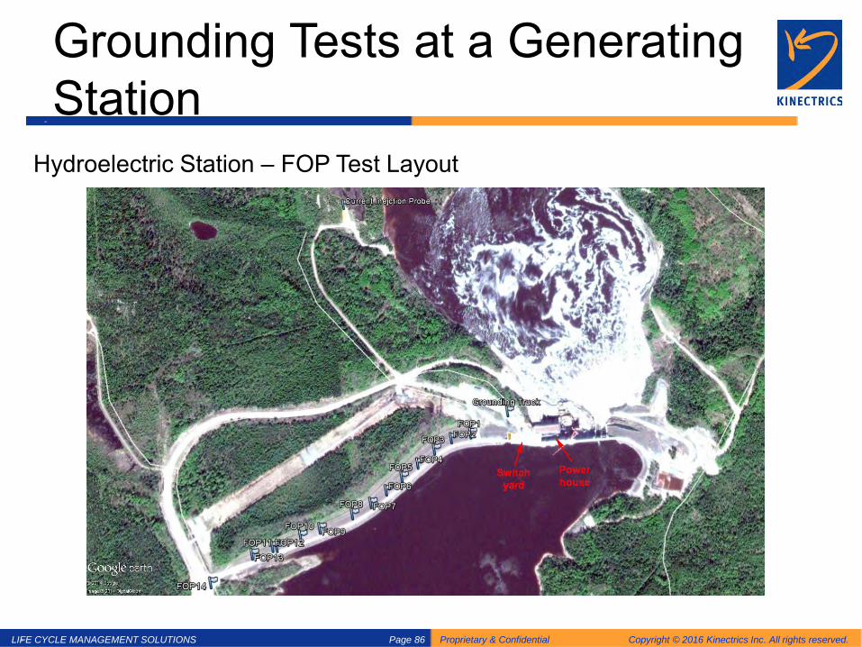
Grounding Tests at a Generating Station
Hydroelectric Station – FOP Test Layout
Source: Kinectrics Inc.
LIFE CYCLE MANAGEMENT SOLUTIONS Proprietary & Confidential Copyright © 2016 Kinectrics Inc. All rights reserved. Page 87
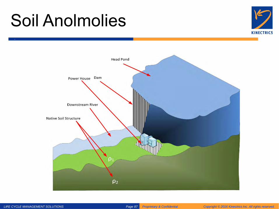
Soil Anolmolies
LIFE CYCLE MANAGEMENT SOLUTIONS Proprietary & Confidential Copyright © 2016 Kinectrics Inc. All rights reserved. Page 88
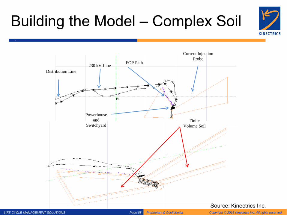
Building the Model – Complex Soil
Current Injection Probe
Finite Volume Soil
FOP Path 230 kV Line Distribution Line
Powerhouse and
Switchyard
Source: Kinectrics Inc.

LIFE CYCLE MANAGEMENT SOLUTIONS Proprietary & Confidential Copyright © 2016 Kinectrics Inc. All rights reserved. Page 89
Ground Grid Performance
• Current injection Test
– Soil Resistivity Testing – Ground Grid Resistance – Current Injection Testing – Step and Touch Potentials
• Integrity Tests

LIFE CYCLE MANAGEMENT SOLUTIONS Proprietary & Confidential Copyright © 2016 Kinectrics Inc. All rights reserved. Page 90
Grid Integrity Tests - Why ?
• Check for dig ins after construction • Test for fused conductors after heavy faults • Measure fence interconnection / isolation • Look for corrosion on connectors • Confirm gradient control at gates • Locate grid conductors

LIFE CYCLE MANAGEMENT SOLUTIONS Proprietary & Confidential Copyright © 2016 Kinectrics Inc. All rights reserved. Page 91
Custom Micro Ohmmeter & Leads
Battery powered (10 A) micro ohmmeter

LIFE CYCLE MANAGEMENT SOLUTIONS Proprietary & Confidential Copyright © 2016 Kinectrics Inc. All rights reserved. Page 92
Grid Integrity Test - How ?
• Measure R between nearby accessible loops • Pace out distance, add vertical loop length • Estimate P as number of parallel conductors • Check routing of grid conductors

LIFE CYCLE MANAGEMENT SOLUTIONS Proprietary & Confidential Copyright © 2016 Kinectrics Inc. All rights reserved. Page 93
Grounding Print with Integrity Nodes
LIFE CYCLE MANAGEMENT SOLUTIONS Proprietary & Confidential Copyright © 2016 Kinectrics Inc. All rights reserved. Page 94
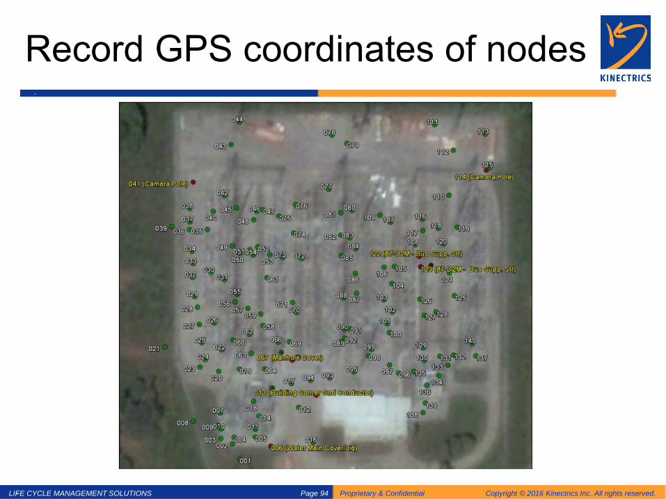
Record GPS coordinates of nodes

LIFE CYCLE MANAGEMENT SOLUTIONS Proprietary & Confidential Copyright © 2016 Kinectrics Inc. All rights reserved. Page 95
Reporting the measurements

LIFE CYCLE MANAGEMENT SOLUTIONS Proprietary & Confidential Copyright © 2016 Kinectrics Inc. All rights reserved. Page 96
Higher than Estimated Values
LIFE CYCLE MANAGEMENT SOLUTIONS Proprietary & Confidential Copyright © 2016 Kinectrics Inc. All rights reserved. Page 97
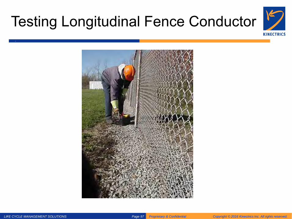
Testing Longitudinal Fence Conductor
LIFE CYCLE MANAGEMENT SOLUTIONS Proprietary & Confidential Copyright © 2016 Kinectrics Inc. All rights reserved. Page 98
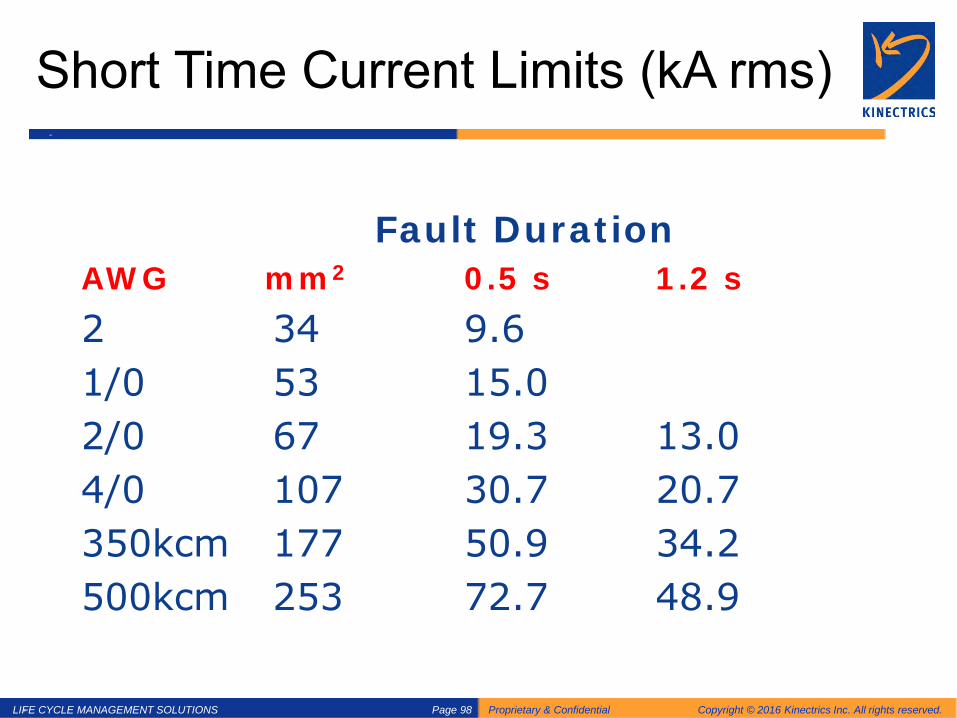
Short Time Current Limits (kA rms)
Fault Duration AWG mm2 0.5 s 1.2 s 2 34 9.6 1/0 53 15.0 2/0 67 19.3 13.0 4/0 107 30.7 20.7 350kcm 177 50.9 34.2 500kcm 253 72.7 48.9

LIFE CYCLE MANAGEMENT SOLUTIONS Proprietary & Confidential Copyright © 2016 Kinectrics Inc. All rights reserved. Page 99
Tests Benefits
Integrity Tests Can Identify: Current Injection Tests Can Identify Bonds not rated for faults Excessive GPR
Structures completely floating Excessive Step Potentials inside the yard and outside on native soil
Major equipment with a single bond (no contingency)
Excessive Touch Potentials on all major equipment inside the yard and station
fence
Missing bonds to equipment Excessive transfer potential to nearby residential houses
High resistance between equipment and the ground grid,
and across gates
Current Splits into external connections (such as skywires/cable concentric neutral)
Part of yard completely isolated Coordination issues with other utilities ( pipeline/gas/water)

LIFE CYCLE MANAGEMENT SOLUTIONS Proprietary & Confidential Copyright © 2016 Kinectrics Inc. All rights reserved. Page 100
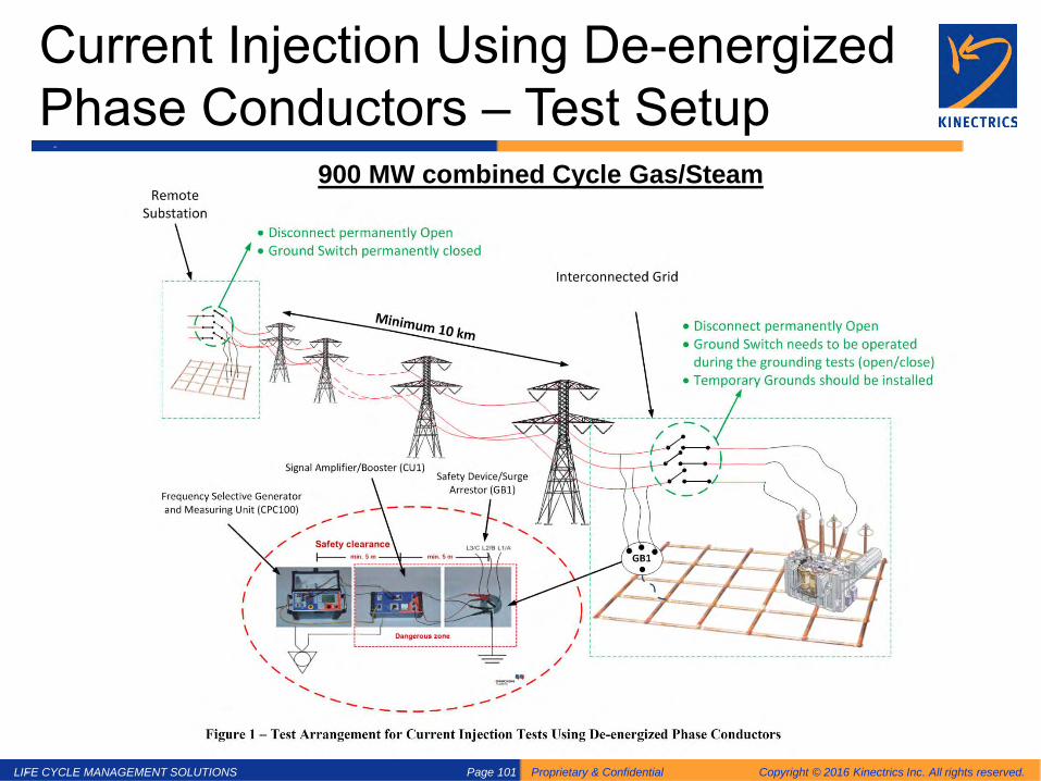
Current Injection Using De-energized Phase Conductors • When the grid footprint is large • Downtown/busy residential areas with multi-
grounded neutral Solution?
– Use grounded phase conductors as the current lead (outage required)
– Needs more powerful equipment – Test fault gets injected from the actual phase
conductor – Higher test fault Better step and touch
measurement
LIFE CYCLE MANAGEMENT SOLUTIONS Proprietary & Confidential Copyright © 2016 Kinectrics Inc. All rights reserved. Page 101
Current Injection Using De-energized Phase Conductors – Test Setup
900 MW combined Cycle Gas/Steam

LIFE CYCLE MANAGEMENT SOLUTIONS Proprietary & Confidential Copyright © 2016 Kinectrics Inc. All rights reserved. Page 102
Questions?


![Model for Calculating the Density and Resistivity of ... · Stichtenoth et al. [2] have reported resistance measurements for p-doped GaAs nanopillars and their relation to hole concentration](https://img.pdfslide.us/doc/110x75/602d272f5d1f53733061670b/model-for-calculating-the-density-and-resistivity-of-stichtenoth-et-al-2.jpg)