Embed Size (px)
Citation preview
© Faculty of Mechanical Engineering, Belgrade. All rights reserved FME Transactions (2019) 47, 560-575 560
Received: November 2018, Accepted: March 2019 Correspondence to: Dr Dhananjay R. Mishra Department of Mechanical Engineering, Jaypee University of Engineering and Technology, India E-mail: [email protected] doi: 10.5937/fmet1903560G
Girish Dutt Gautam
Department of Mechanical Engineering, Jaypee University of Engineering and
Technology, Madhya Pradesh
India
Dhananjay R. Mishra Department of Mechanical Engineering,
Jaypee University of Engineering and Technology,
Madhya Pradesh India
Evaluation of Geometrical Quality Characteristics in Pulsed Nd:YAG Laser Cutting of Kevlar-29/Basalt Fiber Reinforced Hybrid Composite Using Grey Relational Analysis Based on Genetic Algorithm In advanced machining techniques, laser beam cutting provides better control over the cut surface geometry in the cutting of fiber reinforced composites compared with conventional machining techniques due to its non-contact and localized processing. However, the performance of laser cutting for hybrid fiber reinforced polymer composites is yet to reveal. It has paved the way of present study, which reports on the pulsed Nd:YAG laser cutting of 1.35mm thick Kevlar-29 and Basalt fiber based hybrid composite sheet. The geometrical accuracy of the cut has been eveluated by the measured values of kerf width, kerf deviation, and kerf taper for 42 different combinations of five laser-cutting parameters such as lamp current, pulse width, pulse frequency, compressed air pressure and cutting speed. Moreover, an integrated approach based on Grey relational analysis and genetic algorithm (GRGA) has been used for the single index optimizations of different kerf qualities. Furthermore, parametric effects have been also discussed. Keywords: Nd:YAG laser beam cutting; Kevlar fiber; Basalt fiber; Hybrid composite; Kerf quality characteristics; Grey relational analysis based genetic algorithm (GRGA).
1. INTRODUCTION
In recent years, the focus of researchers has shifted from conventional materials to fiber reinforced polymer (FRP) composites for various engineering applications. Distinctive features of FRP composites such as higher stiffness and strength to weight ratio, superior corrosion, and electrical resistant properties, etc. make them sui-table for automobile, marine, aerospace, racing cars, defence etc. sectors. [1,2] However, FRP composites suffer from strength degradation due to delamination during their service life. Thereby, researchers have paved attention to the hybridization of two or more dissimilar types of fibers in a common matrix phase to enhance the performance of composite materials. [3] Fiber hybridization is the process of blending two or more distinct fibers in a common matrix phase to achi-eve improved properties. [4] Various researchers deve-loped different types of hybrid fiber reinforced polymer composites based on their requirement. [5] In the literature survey it has revealed that maximum research work has done for the glass-carbon, glass-aramid, aramid-carbon fiber based hybrid composites etc. [6–8]
In synthetic fibers, Aramid fibers own superior
resistive ability to heat, shocks and scratches. These are prepared by the chemical reactions between the amine group and carboxylic acid halide at DuPont Company in the early 1960s. [9] Kevlar is the most popular type of aramid fiber having tremendous mechanical properties due to its primary, secondary and tertiary chemical structures. It has higher thermo-mechanical properties with better resistant to wear, shock and heat. Kevlar fiber reinforced polymer (KFRP) composites, reinforced by different grades of Kevlar fibers such as K-29, K-49, K-129, etc. are widely using in aerospace, defence, automobile, and marine industries. [10]
In the literature, it has been observed that most of the researches have focused on the hybrid composites of Kevlar fibers with glass and carbon fibers. The unavailability of literature for Kevlar and basalt fiber based hybrid composites encouraged to the present study. However, hybridization of basalt fiber with carbon and glass fiber has significantly improved flexural and impact strength of the composites. [11] Basalt fiber is a natural inorganic fiber obtained by the melting and extrusion process of basalt rocks. It has higher heat resistant properties for a wide range of temperature from -269 to 650°C. Basalt fibers also have higher oxidation, radiation resistive properties with high compression and shear strength. [12] Basalt fiber reinforced polymer (BFRP) composites have a wide range of applications in various engineering sectors as bridge cables, thermal and sound insulation/protection, pipes, bars, fittings, fabrics, structural plastics,
FME Transactions VOL. 47, No 3, 2019 ▪ 561
automotive parts, concrete reinforcement and frictional materials. [13] BFRP composites possess outstanding recyclability properties with stable and higher frictional coefficient. BFRP also have an eco-friendly nature. Recently, researchers have observed that basalt fiber is able to replace glass and carbon fibers for various engi-neering applications due to their excellent mechanical and structural properties with low cost. The hybrid com-posites of Kevlar and basalt fibers provide superior shock resistant properties for ballistic applications. Ban-daru et al. [14] have observed that mechanical behavior of Kevlar and basalt fiber based hybrid composites make them suitable for armours and aerospace appli-cations. In another study [15], they have found that Kevlar and basalt fiber based hybrid composites have higher impact strength with low density.
The cutting of FRP composites is a tough task by using the conventional machining techniques due to the requirement of the higher specific energy. This specific energy is responsible for the development of higher fric-tional forces on the cutting tool and results in a poor product quality. In the conventional cutting of FRP composites, cut quality is also worse due to the whis-ker’s formation, fiber pullout and delamination. [16,17]
In advanced machining techniques, Laser beam cutting (LBC) offers several advantages over conven-tional machining of FRP composites due to its non-contact nature. LBC eliminates cutting and vibration forces in the process thus no tool wear and deflection occur as compared to conventional techniques. [18] In literature survey, it has found that LBC has the capa-bility to cut various types of FRP composites such as glass fiber reinforced polymer (GFRP) composites [19–21], carbon fiber reinforced polymer (CFRP) compo-sites [22–24], Kevlar fiber reinforced polymer (KFRP) composites [10,16,25–27] etc. with a higher degree of precision accuracy and reproducibility. In laser cutting process, proper selection of machining parameters are required for accomplishing accurate geometry of cut.
Various researchers employed a number of opti-mization techniques to achieve the optimum levels of laser cutting parameters for FRP composites. Gautam and Pandey [16] employed a Teaching learning algo-rithm based optimization of Nd:YAG laser cutting para-meters of Kevlar composite laminate. They used lamp current, pulse width, pulse frequency, compressed air pressure and cutting speed as input variables to measure the top and bottom kerf deviation. They revealed that cutting speed and lamp current was the most significant factor for the top and bottom kerf deviation, respectively. Rao et al. [28] have used response surface methodology (RSM) to optimize laser parameters such as laser power, beam scanning speed and assist gas flow rate to achieve higher cutting surface quality in terms of kerf width, taper percentage, and heat affected zone. They observed a remarkable improvement in cut quality characteristics. Hossain et al. [29] employed the fuzzy expert system to predict the optimal values of laser power, cutting speed, stand-off distance and assist gas pressure to achieve better kerf width. They observed that developed fuzzy expert system predict kerf width with 0.385% relative error with experimental results. Madic et al. [30] have used grey relational analysis
(GRA) technique to determine optimal values of laser cutting parameters such as laser power, cutting speed, assist gas pressure and focus position to simultaneously improve the depth of separation line, drag-line separation, and burr height. GRA also successfully implemented by Palanikumar et al. [31] to obtain an optimal set of drilling parameters for glass fiber reinforced polymer composite. Therefore, the appropriate selection of laser parameters is required to achieve a better geometry of cut. This is the reason for the motivation of the present research work.
A thorough scrutiny of the literature has clearly indicated that the potential of laser cutting on Kevlar-basalt fiber based hybrid composites yet to reveal. Keeping this fact in mind, the present study has carried out. In the present work, the main aim is to achieve a better geometry of cut during pulsed Nd:YAG laser cutting of Kevlar-29/basalt fiber based hybrid composites by identifying optimal settings of laser cutting parameters such as lamp current (I), pulse width (PW), pulse frequency (f), compressed air pressure (p) and cutting speed (S). Because of this, key kerf quality characteristics viz. kerf width, kerf deviation, and kerf taper have attempted to minimize. Therefore, a multi-objective optimization has carried out by using a hybrid grey relational analysis based genetic algorithm (GRGA) optimization technique. Further, to identify the behavior of hybrid composite surface during laser cutting the effects of laser process parameters on single index of multiple kerf quality characteristics have also discussed. Finally, confirmation experiments have conducted to validate the obtained optimal solutions.
2. METHODOLOGY, MATERIAL AND EXPERI-
MENTATION 2.1 Methodology
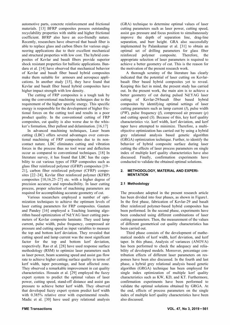
The procedure adopted in the present research article has been divided into four phases, as shown in Figure1. In the first phase, fabrication of Kevlar-29 and basalt fiber reinforced polymer-based hybrid composites has been performed. In the second phase, experiments have been conducted using different combinations of laser cutting parameters. Then, the measurement of the values of different geometrical cut quality characteristics has been carried out.
Third phase consists of the development of mathe-matical models of kerf width, kerf deviation, and kerf taper. In this phase, Analysis of variances (ANOVA) has been performed to check the adequacy and relia-bility of developed models. Moreover, percentage con-tribution effects of different laser parameters on res-ponses have been also discussed. In the fourth and last phase, a hybrid grey relational analysis based genetic algorithm (GRGA) technique has been employed for single index optimization of multiple kerf quality characteristics such as KW, KD, and KT. Furthermore, confirmation experiments have been performed to validate the optimal solutions obtained by GRGA. At the end, effects of process parameters on the single index of multiple kerf quality characteristics have been also discussed.
FME Transactions VOL. 47, No 3, 2019 ▪ 562
Figure 1. Phase diagram of methodology
2.2 Fabrication of Kevlar-29/Basalt fiber reinforced polymer based hybrid composite
In this research, for the fabrication of hybrid composite sheets, hand lay-up technique was used. This is the most practiced composite fabrication method due to lower setup and tooling cost compared to other techniques like resin transfer molding. Hand lay-up technique is widely used in the fabrication of various components in automotive and aircraft industries. In this study, a sheet of novel hybrid composite sheet reinforced by Kevlar-29 and Basalt fiber has fabricated for experimentation. Aerotech Technical Textile, Mumbai, India, supplied woven fabrics of Kevlar-29 and basalt fibers of 200 gsm thick. Whereas, epoxy resin-520 and hardner-509 manufactured by Electro coating & Insulation Technical Pvt. Ltd., Pune, India, were used as a polymeric binding agent. The ingredient materials for fabricated hybrid composite are tabulated in Table 1. Table 1. The ingredient materials of hybrid composite laminate
Ingredient Material Type Woven pattern
Reinforcement
Kevlar-29 fabric
Bi-directional (200 g/m2) Plain
Basalt fabric
Bi-directional (200 g/m2) Plain
Matrix (10:1 ratio)
Epoxy resin LY-520
Hardener HY-509 A mild steel mold having dimensions of 300
mm×300 mm×20 mm is used in fabrication process of hybrid composite laminates within the laboratory. Tailored pieces of kevlar-29 and basalt fiber fabrics have used. Then, epoxy and hardener were mixed together in a weight ratio of 10:1 to prepare resin glue by using a stirrer. Moreover, a silicon spray was used as a releasing agent to ease removal of the fabricated composite sheet. After this, resin glue was sprayed on the mold surface by a brush and one mat of the Kevlar-29 fabric is placed. Then, a layer of basalt fiber fabric was placed over the base layer of kevlar-29 fiber. This process was repeated for the seven layers of fiber
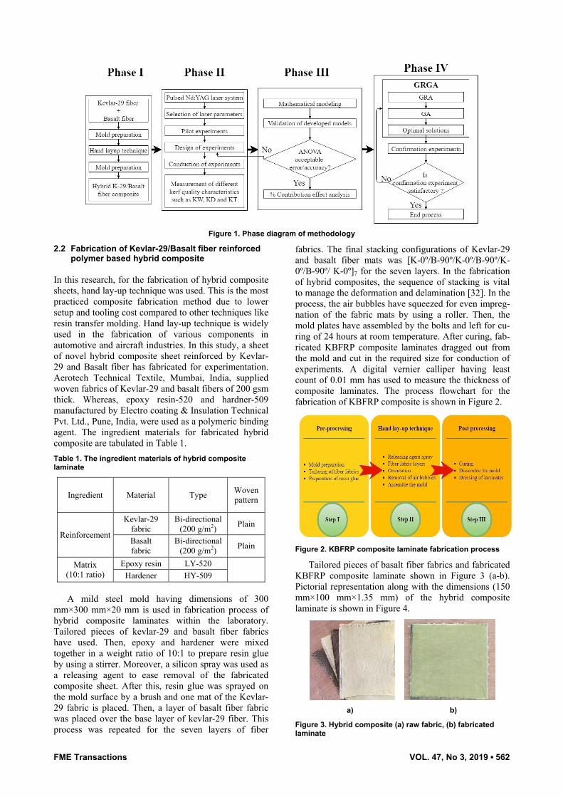
fabrics. The final stacking configurations of Kevlar-29 and basalt fiber mats was [K-0º/B-90º/K-0º/B-90º/K-0º/B-90º/ K-0º]7 for the seven layers. In the fabrication of hybrid composites, the sequence of stacking is vital to manage the deformation and delamination [32]. In the process, the air bubbles have squeezed for even impreg-nation of the fabric mats by using a roller. Then, the mold plates have assembled by the bolts and left for cu-ring of 24 hours at room temperature. After curing, fab-ricated KBFRP composite laminates dragged out from the mold and cut in the required size for conduction of experiments. A digital vernier calliper having least count of 0.01 mm has used to measure the thickness of composite laminates. The process flowchart for the fabrication of KBFRP composite is shown in Figure 2.
Figure 2. KBFRP composite laminate fabrication process
Tailored pieces of basalt fiber fabrics and fabricated KBFRP composite laminate shown in Figure 3 (a-b). Pictorial representation along with the dimensions (150 mm×100 mm×1.35 mm) of the hybrid composite laminate is shown in Figure 4.
a) b)
Figure 3. Hybrid composite (a) raw fabric, (b) fabricated laminate
FME Transactions VOL. 47, No 3, 2019 ▪ 563
Figure 4. Dimensions of Hybrid composite laminate
2.3 Laser setup & experimentation
In this research work, a pulsed Nd:YAG laser system developed at Raja Rammana Centre of Advanced Tech-nology (RRCAT), Indore, India, having 250W average output power and three axes CNC-controlled table has used for the cutting of the Kevlar-basalt hybrid compo-site laminate. Compressed air has used as an assist gas to expel molten material from the cut surface. It is requ-ired for protecting the focusing lens from emitted fume due to vaporization and burning of the work piece ma-terial. Moreover, standoff distance between the nozzle and specimen has fixed at 1 mm and kept constant for the entire range of experiments. Table 2 shows the specifications of the pulsed Nd: YAG laser system used in this research work. Table 2. Nd:YAG laser parameters and their levels
Factor Unit Level 1
Level 2
Level 3
Lamp current (I) Amp 160 180 200
Pulse width (PW) ms 2 2.3 2.6 Pulse frequency (f) Hz 20 25 30 Compressed air pressure (p) kg/cm2 8 9 10
Cutting speed (S) mm/min 50 100 200 2.4 Evaluation of geometrical quality characteristics
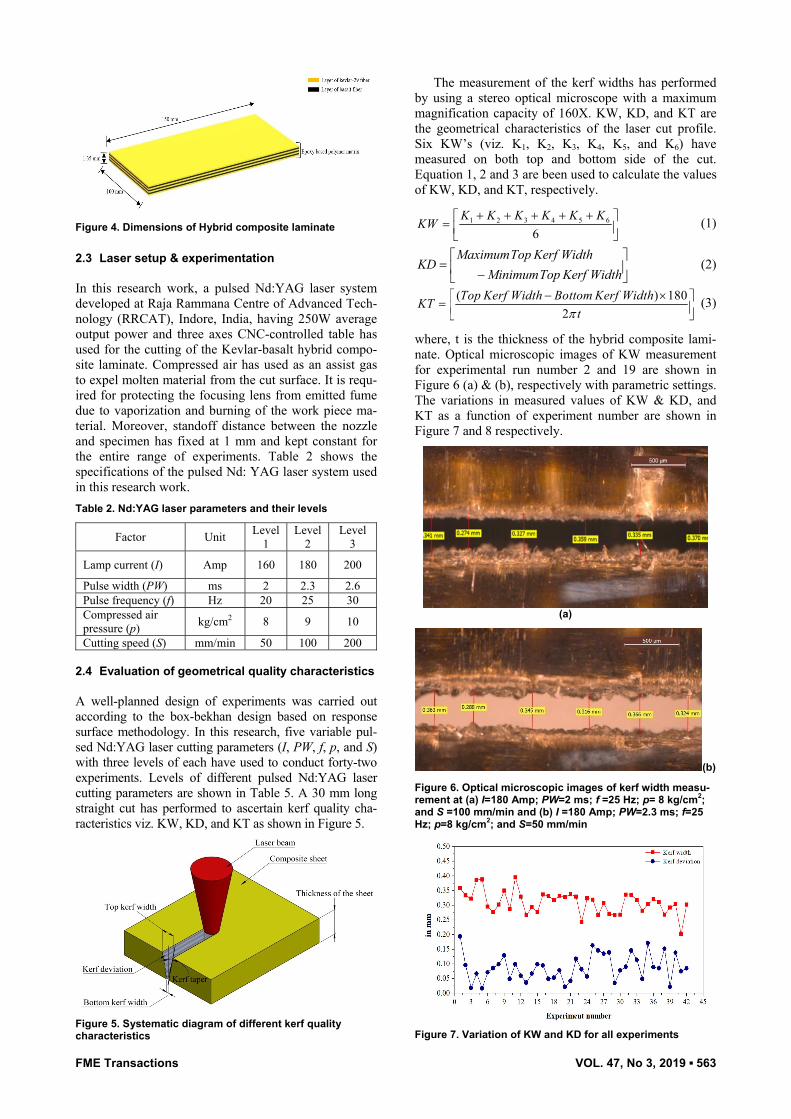
A well-planned design of experiments was carried out according to the box-bekhan design based on response surface methodology. In this research, five variable pul-sed Nd:YAG laser cutting parameters (I, PW, f, p, and S) with three levels of each have used to conduct forty-two experiments. Levels of different pulsed Nd:YAG laser cutting parameters are shown in Table 5. A 30 mm long straight cut has performed to ascertain kerf quality cha-racteristics viz. KW, KD, and KT as shown in Figure 5.
Figure 5. Systematic diagram of different kerf quality characteristics
The measurement of the kerf widths has performed by using a stereo optical microscope with a maximum magnification capacity of 160X. KW, KD, and KT are the geometrical characteristics of the laser cut profile. Six KW’s (viz. K1, K2, K3, K4, K5, and K6) have measured on both top and bottom side of the cut. Equation 1, 2 and 3 are been used to calculate the values of KW, KD, and KT, respectively.
1 2 3 4 5 6
6K K K K K K
KW+ + + + +⎡ ⎤= ⎢ ⎥⎣ ⎦
(1)
MaximumTop Kerf WidthKD
MinimumTop Kerf Width⎡ ⎤
= ⎢ ⎥−⎣ ⎦ (2)
( ) 1802
Top Kerf Width Bottom Kerf WidthKTtπ
− ×⎡ ⎤= ⎢ ⎥⎣ ⎦ (3)
where, t is the thickness of the hybrid composite lami-nate. Optical microscopic images of KW measurement for experimental run number 2 and 19 are shown in Figure 6 (a) & (b), respectively with parametric settings. The variations in measured values of KW & KD, and KT as a function of experiment number are shown in Figure 7 and 8 respectively.
(a)
(b)
Figure 6. Optical microscopic images of kerf width measu-rement at (a) I=180 Amp; PW=2 ms; f =25 Hz; p= 8 kg/cm2; and S =100 mm/min and (b) I =180 Amp; PW=2.3 ms; f=25 Hz; p=8 kg/cm2; and S=50 mm/min
Figure 7. Variation of KW and KD for all experiments
FME Transactions VOL. 47, No 3, 2019 ▪ 564
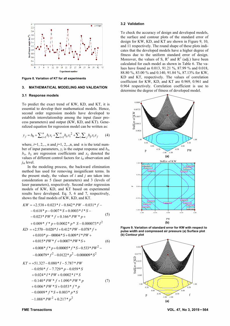
Figure 8. Variation of KT for all experiments
3. MATHEMATICAL MODELING AND VALIDATION 3.1 Response models
To predict the exact trend of KW, KD, and KT, it is essential to develop their mathematical models. Hence, second order regression models have developed to establish interrelationship among the input (laser pro-cess parameters) and output (KW, KD, and KT). Gene-ralized equation for regression model can be written as:
20 1 1
n nj i i ii i ij i ji i i jy b b x b x b x x= == + + +∑ ∑ ∑ ∑ (4)
where, i=1, 2,.., n and j=1, 2,..,n, and n is the total num-ber of input parameters, yj is the output response and b0, bii, bij are regression coefficients and xij denoted the values of different control factors for ith observation and jth level.
In the modeling process, the backward elimination method has used for removing insignificant terms. In the present study, the values of i and j are taken into consideration as 5 (laser parameters) and 3 (levels of laser parameters), respectively. Second order regression models of KW, KD, and KT based on experimental results have developed. Eq. 5, 6 and 7, respectively, shows the final models of KW, KD, and KT.
2
2.538 0.023* 0.842* 0.031*0.618* 0.007* 0.0003* *0.023* * 0.166* *
0.009* * 0.0002* * 0.000073*
KW I PW fp S I SPW f PW p
f p p S I
= + + − − −− − + −− + +
+ + −
(5)
2
2 2 2
2.570 0.020* 0.412* 0.078*0.010* 00004* 0.009* *0.015* * 0.0007* *
0.008* * 0.00005* * 0.533*
0.00079* 0.0122* 0.000009*
KD I PW fp S I PWPW f PW S
f p f S PW
f p S
= + − + − ++ − + ++ + +
+ + − −
− − −
(6)
2 2
51.327 0.080* 5.787*0.050* 7.729* 0.059*0.024* * 0.0002* *0.140* * 1.090* *0.006* * 0.053* *0.0009* * 0.003* *
1.088* 0.217*
KT I PWf p SI PW I SPW f PW pPW S f p
f S p S
PW p
= + − −− − −+ +− ++ +− +
− +
(7)
3.2 Validation
To check the accuracy of design and developed models, the surface and contour plots of the standard error of design for KW, KD, and KT are shown in Figure 9, 10, and 11 respectively. The round shape of these plots indi-cates that the developed models have a higher degree of fitness due to the uniform standard error of design. Moreover, the values of S, R2 and R2 (adj.) have been calculated for each model as shown in Table 6. The va-lues have found as 0.013, 91.21 %, 87.99 % and 0.018, 88.80 %, 83.00 % and 0.140, 91.84 %, 87.13% for KW, KD and KT, respectively. The values of correlation coefficient for KW, KD, and KT are 0.969, 0.961 and 0.964 respectively. Correlation coefficient is use to determine the degree of fitness of developed model.
-1.00 -0.50
0.00 0.50
1.00
-1.00 -0.50
0.00 0.50
1.00
0.0026
0.00415
0.0057
0.00725
0.0088
Std
Err o
f KW
PW p
(a)
-1.00 -0.50 0.00 0.50 1.00
-1.00
-0.50
0.00
0.50
1.00StdErr of KW
PW
p
0.003696090.0047037
0.0047037
0.0047037 0.0047037
0.00571131 0.00571131
0.005711310.00571131
0.006718920.00671892
0.006718920.00671892
0.00772653
22
(b)
Figure 9. Variation of standard error for KW with respect to pulse width and compressed air pressure (a) Surface plot (b) Contour plot
-1.00 -0.50
0.00 0.50
1.00
-1.00 -0.50
0.00 0.50
1.00
0.005
0.00925
0.0135
0.01775
0.022
Std
Err o
f KD
f p
(a)
FME Transactions VOL. 47, No 3, 2019 ▪ 565
-1.00 -0.50 0.00 0.50 1.00
-1.00
-0.50
0.00
0.50
1.00StdErr of KD
f
p
0.00808397
0.0108175 0.0108175
0.0108175 0.0108175
0.0135511 0.0135511
0.0135511 0.0135511
0.0162847 0.0162847
0.0162847 0.0162847
0.0190182 0.0190182
22
(b)
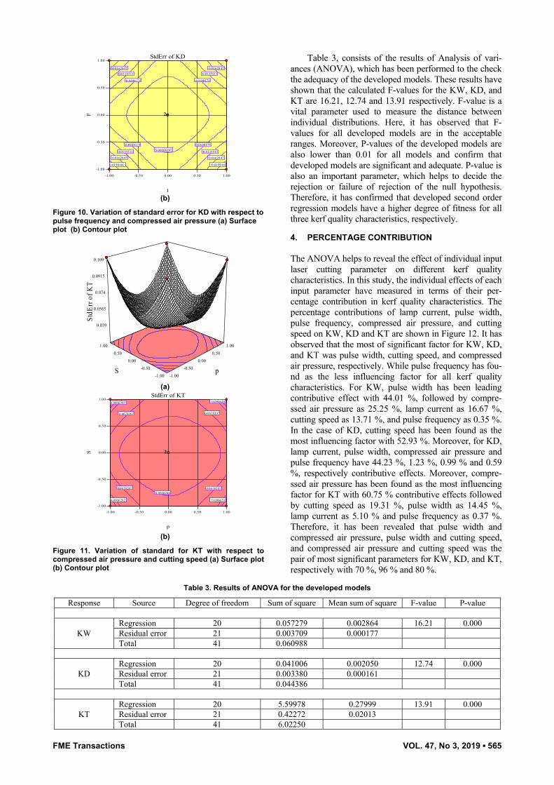
Figure 10. Variation of standard error for KD with respect to pulse frequency and compressed air pressure (a) Surface plot (b) Contour plot
-1.00 -0.50
0.00 0.50
1.00
-1.00 -0.50
0.00 0.50
1.00
0.039
0.0565
0.074
0.0915
0.109
Std
Err o
f KT
p S
(a)
-1.00 -0.50 0.00 0.50 1.00
-1.00
-0.50
0.00
0.50
1.00StdErr of KT
p
S
0.0506246
0.0906292 0.0906292
0.0906292 0.0906292
0.0678207 0.0678207
0.0678207 0.0678207
22
(b)
Figure 11. Variation of standard for KT with respect to compressed air pressure and cutting speed (a) Surface plot (b) Contour plot
Table 3, consists of the results of Analysis of vari-ances (ANOVA), which has been performed to the check the adequacy of the developed models. These results have shown that the calculated F-values for the KW, KD, and KT are 16.21, 12.74 and 13.91 respectively. F-value is a vital parameter used to measure the distance between individual distributions. Here, it has observed that F-values for all developed models are in the acceptable ranges. Moreover, P-values of the developed models are also lower than 0.01 for all models and confirm that developed models are significant and adequate. P-value is also an important parameter, which helps to decide the rejection or failure of rejection of the null hypothesis. Therefore, it has confirmed that developed second order regression models have a higher degree of fitness for all three kerf quality characteristics, respectively. 4. PERCENTAGE CONTRIBUTION
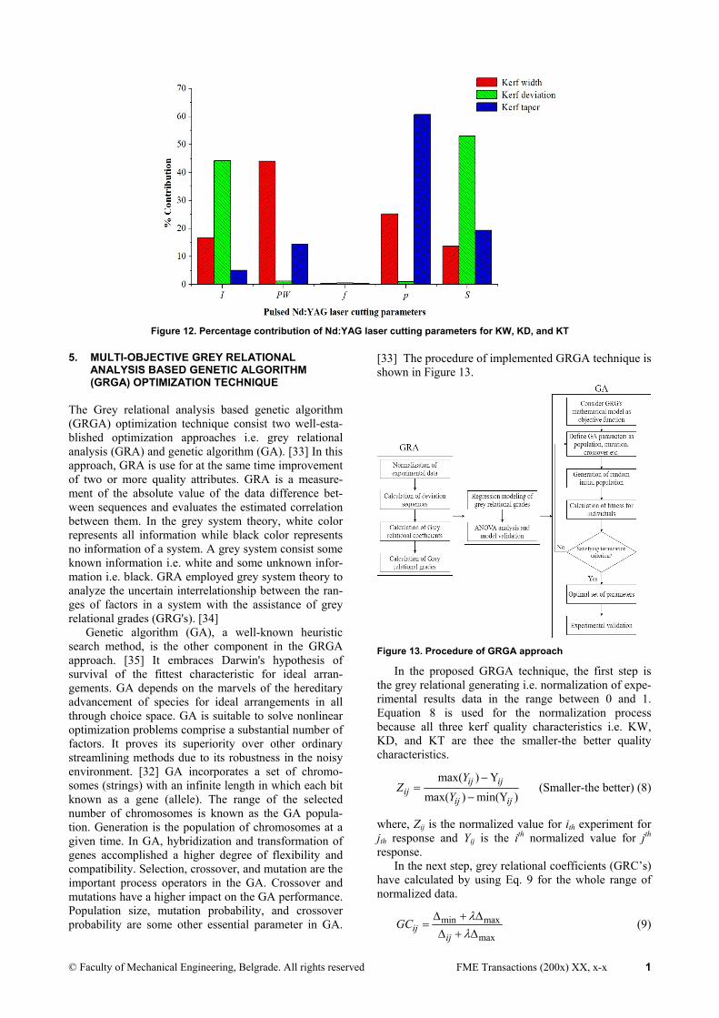
The ANOVA helps to reveal the effect of individual input laser cutting parameter on different kerf quality characteristics. In this study, the individual effects of each input parameter have measured in terms of their per-centage contribution in kerf quality characteristics. The percentage contributions of lamp current, pulse width, pulse frequency, compressed air pressure, and cutting speed on KW, KD and KT are shown in Figure 12. It has observed that the most of significant factor for KW, KD, and KT was pulse width, cutting speed, and compressed air pressure, respectively. While pulse frequency has fou-nd as the less influencing factor for all kerf quality characteristics. For KW, pulse width has been leading contributive effect with 44.01 %, followed by compre-ssed air pressure as 25.25 %, lamp current as 16.67 %, cutting speed as 13.71 %, and pulse frequency as 0.35 %. In the case of KD, cutting speed has been found as the most influencing factor with 52.93 %. Moreover, for KD, lamp current, pulse width, compressed air pressure and pulse frequency have 44.23 %, 1.23 %, 0.99 % and 0.59 %, respectively contributive effects. Moreover, compre-ssed air pressure has been found as the most influencing factor for KT with 60.75 % contributive effects followed by cutting speed as 19.31 %, pulse width as 14.45 %, lamp current as 5.10 % and pulse frequency as 0.37 %. Therefore, it has been revealed that pulse width and compressed air pressure, pulse width and cutting speed, and compressed air pressure and cutting speed was the pair of most significant parameters for KW, KD, and KT, respectively with 70 %, 96 % and 80 %.
Table 3. Results of ANOVA for the developed models
Response Source Degree of freedom Sum of square Mean sum of square F-value P-value
KW Regression 20 0.057279 0.002864 16.21 0.000 Residual error 21 0.003709 0.000177 Total 41 0.060988
KD Regression 20 0.041006 0.002050 12.74 0.000 Residual error 21 0.003380 0.000161 Total 41 0.044386
KT Regression 20 5.59978 0.27999 13.91 0.000 Residual error 21 0.42272 0.02013 Total 41 6.02250
© Faculty of Mechanical Engineering, Belgrade. All rights reserved FME Transactions (200x) XX, x-x 1
Figure 12. Percentage contribution of Nd:YAG laser cutting parameters for KW, KD, and KT
5. MULTI-OBJECTIVE GREY RELATIONAL ANALYSIS BASED GENETIC ALGORITHM (GRGA) OPTIMIZATION TECHNIQUE
The Grey relational analysis based genetic algorithm (GRGA) optimization technique consist two well-esta-blished optimization approaches i.e. grey relational analysis (GRA) and genetic algorithm (GA). [33] In this approach, GRA is use for at the same time improvement of two or more quality attributes. GRA is a measure-ment of the absolute value of the data difference bet-ween sequences and evaluates the estimated correlation between them. In the grey system theory, white color represents all information while black color represents no information of a system. A grey system consist some known information i.e. white and some unknown infor-mation i.e. black. GRA employed grey system theory to analyze the uncertain interrelationship between the ran-ges of factors in a system with the assistance of grey relational grades (GRG's). [34]
Genetic algorithm (GA), a well-known heuristic search method, is the other component in the GRGA approach. [35] It embraces Darwin's hypothesis of survival of the fittest characteristic for ideal arran-gements. GA depends on the marvels of the hereditary advancement of species for ideal arrangements in all through choice space. GA is suitable to solve nonlinear optimization problems comprise a substantial number of factors. It proves its superiority over other ordinary streamlining methods due to its robustness in the noisy environment. [32] GA incorporates a set of chromo-somes (strings) with an infinite length in which each bit known as a gene (allele). The range of the selected number of chromosomes is known as the GA popula-tion. Generation is the population of chromosomes at a given time. In GA, hybridization and transformation of genes accomplished a higher degree of flexibility and compatibility. Selection, crossover, and mutation are the important process operators in the GA. Crossover and mutations have a higher impact on the GA performance. Population size, mutation probability, and crossover probability are some other essential parameter in GA.
[33] The procedure of implemented GRGA technique is shown in Figure 13.
Figure 13. Procedure of GRGA approach
In the proposed GRGA technique, the first step is the grey relational generating i.e. normalization of expe-rimental results data in the range between 0 and 1. Equation 8 is used for the normalization process because all three kerf quality characteristics i.e. KW, KD, and KT are thee the smaller-the better quality characteristics.
max( ) Ymax( ) min(Y )
ij ijij
ij ij
YZ
Y−
=−
(Smaller-the better) (8)
where, Zij is the normalized value for ith experiment for jth response and Yij is the ith normalized value for jth
response. In the next step, grey relational coefficients (GRC’s)
have calculated by using Eq. 9 for the whole range of normalized data.
min max
maxij
ijGC
λλ
Δ + Δ=
Δ + Δ (9)
FME Transactions VOL. 47, No 3, 2019 ▪ 567
where, GCij is the grey relational coefficient for the ith experiment and jth response. ∆ is the absolute difference between Yoj and Yij; here Yoj is the ideal normalized value of jth response. ∆min and ∆max are minimum and maximum values of ∆, respectively. λ is the distin-guishing coefficient having range 0 ≤ λ≤1. In this study, the value of λ is taken as 0.5.
Weighting ratio 1:1:1 was set for all three kerf quality characteristics for incorporating the GRC’s into the grey relational grade for each experiment. Grey relational grades (Gi) were computed as per Eq. 10.
1i ijG GC
m= ∑ (10)
where, m is the number of responses. After calculating GRG’s for all experimental runs, a
second-order regression model of GRG’s has developed. This developed mathematical model used as an objective function for GA based optimization. After defining GA parameters such as population size, crossover probability and mutation probability, etc. initial random population is generated. If the fitness of objective function found satis-
fied then terminate the program otherwise change in parameters settings. This process is repeated until to achieve the best fitness value of the function.
6. RESULTS AND DISCUSSION 6.1 Grey relational grades modeling
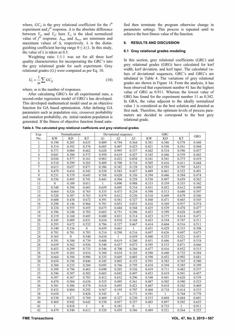
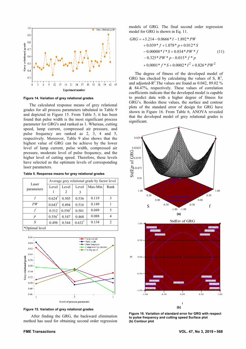
In this section, grey relational coefficients (GRC) and grey relational grades (GRG) have calculated for kerf width, kerf deviation, and kerf taper. The calculated va-lues of deviational sequences, GRC’s and GRG’s are tabulated in Table 4. The variations of grey relational grades are shown in Figure 14. From the analysis, it has been observed that experiment number 41 has the highest value of GRG as 0.911. Whereas the lowest value of GRG has found for the experiment number 11 as 0.342. In GRA, the value adjacent to the ideally normalized value 1 is considered as the best solution and denoted as first rank. Therefore, the optimum levels of process para-meters are decided to correspond to the best grey relational grade.
Table 4. The calculated grey relational coefficients and grey relational grades
Exp. No.
Normalization Deviational sequence GRC GRG KW KD KT Δ1 Δ2 Δ3 KW KD KT 1 0.190 0.205 0.635 0.809 0.794 0.364 0.381 0.386 0.578 0.448 2 0.314 0.592 0.576 0.685 0.407 0.423 0.421 0.550 0.541 0.504 3 0.371 0.004 0.662 0.628 0.995 0.337 0.442 0.334 0.596 0.457 4 0.041 0.380 0.572 0.958 0.619 0.427 0.342 0.446 0.539 0.442 5 0.036 0.577 0.161 0.963 0.422 0.838 0.341 0.541 0.373 0.419 6 0.510 0.299 0.283 0.489 0.700 0.716 0.505 0.416 0.411 0.444 7 0.613 0.657 0.871 0.386 0.342 0.128 0.563 0.593 0.795 0.651 8 0.479 0.416 0.542 0.520 0.583 0.457 0.489 0.461 0.522 0.491 9 0.231 0.379 0.643 0.768 0.620 0.356 0.394 0.446 0.584 0.474
10 0.556 0.495 0.741 0.443 0.504 0.258 0.530 0.497 0.659 0.562 11 0 0.109 0.011 1 0.890 0.988 0.333 0.359 0.335 0.342 12 0.340 0.394 0.683 0.659 0.605 0.316 0.431 0.452 0.612 0.498 13 0.664 0.526 0.765 0.335 0.473 0.234 0.598 0.513 0.680 0.597 14 0.520 0.387 0.763 0.479 0.612 0.236 0.510 0.449 0.678 0.546 15 0.608 0.438 0.672 0.391 0.561 0.327 0.560 0.471 0.603 0.545 16 0.298 0.146 0.966 0.701 0.853 0.033 0.416 0.369 0.937 0.574 17 0.324 0.555 0.455 0.675 0.444 0.544 0.425 0.529 0.478 0.477 18 0.396 0.248 0.703 0.603 0.751 0.296 0.453 0.399 0.628 0.493 19 0.319 0.168 0.685 0.680 0.831 0.314 0.423 0.375 0.614 0.471 20 0.345 0.089 0.831 0.654 0.910 0.168 0.433 0.354 0.747 0.511 21 0.293 0.672 0.532 0.706 0.327 0.467 0.414 0.604 0.516 0.511 22 0.340 0.336 0 0.659 0.663 1 0.431 0.429 0.333 0.398 23 0.783 0.701 0.783 0.216 0.298 0.216 0.697 0.626 0.697 0.673 24 0.365 0 0.540 0.634 1 0.459 0.440 0.333 0.521 0.431 25 0.391 0.380 0.739 0.608 0.619 0.260 0.451 0.446 0.657 0.518 26 0.659 0.562 0.926 0.340 0.437 0.073 0.595 0.533 0.871 0.666 27 0.453 0.299 0.733 0.546 0.700 0.266 0.477 0.416 0.652 0.515 28 0.639 0.365 0.816 0.360 0.634 0.183 0.580 0.440 0.732 0.584 29 0.664 0.394 0.996 0.335 0.605 0.003 0.598 0.452 0.992 0.681 30 0.654 0.196 0.846 0.345 0.803 0.153 0.591 0.383 0.765 0.580 31 0.304 0.233 0.204 0.695 0.766 0.795 0.418 0.394 0.385 0.399 32 0.309 0.796 0.463 0.690 0.203 0.536 0.419 0.711 0.482 0.537 33 0.396 0.307 0.502 0.603 0.692 0.497 0.453 0.419 0.501 0.457 34 0.587 0.367 0.703 0.412 0.632 0.296 0.548 0.441 0.628 0.539 35 0.474 0.504 0.638 0.525 0.495 0.361 0.487 0.502 0.580 0.523 36 0.381 0.306 0.578 0.618 0.693 0.421 0.447 0.418 0.542 0.469 37 0.432 0.804 0.292 0.567 0.195 0.707 0.468 0.718 0.414 0.533 38 0.654 1 0.828 0.345 0 0.171 0.591 1 0.744 0.778 39 0.530 0.672 0.769 0.469 0.327 0.230 0.515 0.604 0.684 0.601 40 0.469 0.942 0.642 0.530 0.057 0.357 0.485 0.897 0.582 0.655 41 1 0.818 1 0 0.181 0 1 0.733 1 0.911 42 0.479 0.540 0.613 0.520 0.459 0.386 0.489 0.521 0.564 0.525
FME Transactions VOL. 47, No 3, 2019 ▪ 568
Figure 14. Variation of grey relational grades
The calculated response means of grey relational grades for all process parameters tabulated in Table 9 and depicted in Figure 15. From Table 5, it has been found that pulse width is the most significant process parameter for GRG's and ranked as 1. Whereas, cutting speed, lamp current, compressed air pressure, and pulse frequency are ranked as 2, 3, 4 and 5, respectively. Moreover, Table 9 also shows that the highest value of GRG can be achieve by the lower level of lamp current, pulse width, compressed air pressure, moderate level of pulse frequency, and the higher level of cutting speed. Therefore, these levels have selected as the optimum levels of corresponding laser parameters. Table 5. Response means for grey relational grades
Laser parameters
Average grey relational grade by factor level Level
1 Level
2 Level
3 Max-Min Rank
I 0.624* 0.505 0.536 0.119 3 PW 0.643* 0.494 0.516 0.149 1
f 0.512 0.550* 0.501 0.049 5 p 0.556* 0.547 0.468 0.088 4 S 0.498 0.544 0.632* 0.134 2
*Optimal level
Figure 15. Variation of grey relational grades
After finding the GRG, the backward elimination method has used for obtaining second order regression
models of GRG. The final second order regression model for GRG is shown in Eq. 11.
2 2
3.214 0.0666* 1.892*0.039* 1.078* 0.012*0.00008* * 0.034* *0.325* * 0.015* *
0.0001* * 0.0002* 0.826*
GRG I PWf p S
I S PW fPW p f p
f S I PW
= + − −+ + +− +− −
+ + +
(11)
The degree of fitness of the developed model of GRG has checked by calculating the values of S, R2, and adjusted-R2.The values are found as 0.042, 89.02 % & 84.47%, respectively. These values of correlation coefficients indicate that the developed model is capable to predict data with a higher degree of fitness for GRG’s. Besides these values, the surface and contour plots of the standard error of design for GRG have shown in Figure 16. From Table 6, ANOVA revealed that the developed model of grey relational grades is significant.
-1.00 -0.50
0.00 0.50
1.00
-1.00 -0.50
0.00 0.50
1.00
0.01
0.01475
0.0195
0.02425
0.029
Std
Err o
f GRG
f S
(a)
-1.00 -0.50 0.00 0.50 1.00
-1.00
-0.50
0.00
0.50
1.00StdErr of GRG
f
S
0.0133952
0.0163535 0.0163535
0.0163535 0.0163535
0.0193119 0.0193119
0.0193119 0.0193119
0.0222703 0.0222703
0.0222703 0.0222703
0.0252287 0.0252287
22
(b)
Figure 16. Variation of standard error for GRG with respect to pulse frequency and cutting speed Surface plot (b) Contour plot
FME Transactions VOL. 47, No 3, 2019 ▪ 569
Table 7. ANOVA for grey relational grades
Source Sum of squares DF Mean square F-value P-value
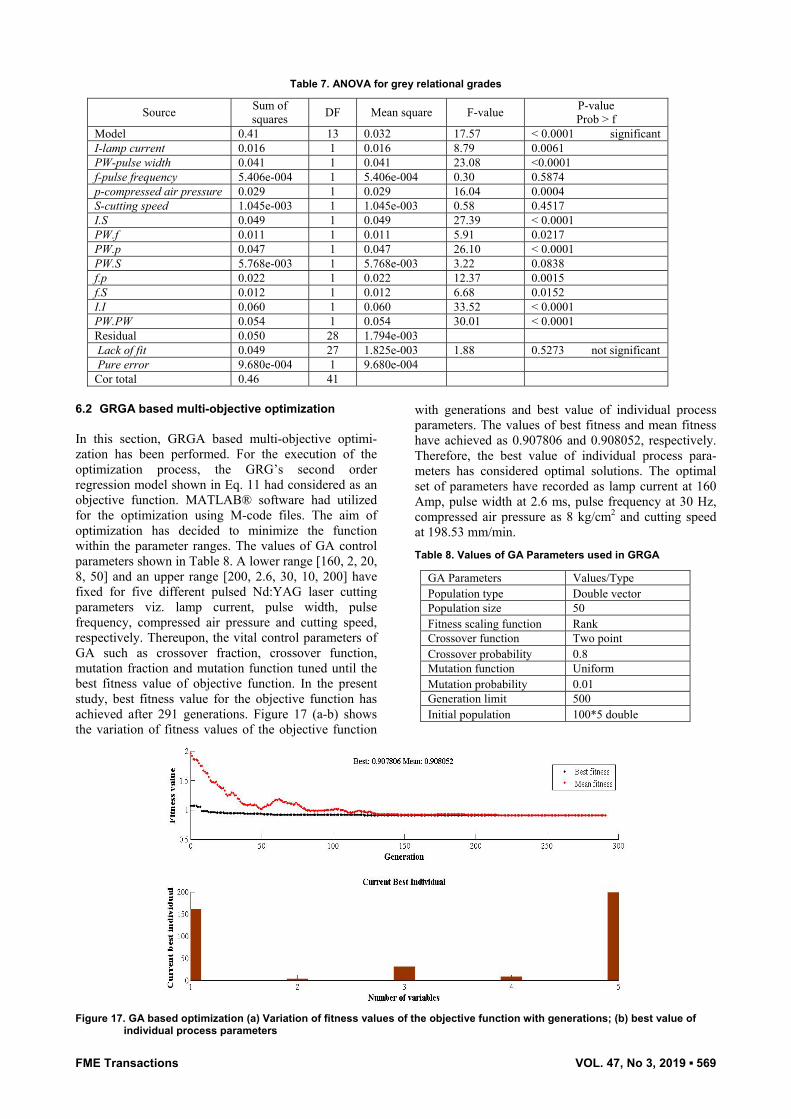
Prob > f Model 0.41 13 0.032 17.57 < 0.0001 significant I-lamp current 0.016 1 0.016 8.79 0.0061 PW-pulse width 0.041 1 0.041 23.08 <0.0001 f-pulse frequency 5.406e-004 1 5.406e-004 0.30 0.5874 p-compressed air pressure 0.029 1 0.029 16.04 0.0004 S-cutting speed 1.045e-003 1 1.045e-003 0.58 0.4517 I.S 0.049 1 0.049 27.39 < 0.0001 PW.f 0.011 1 0.011 5.91 0.0217 PW.p 0.047 1 0.047 26.10 < 0.0001 PW.S 5.768e-003 1 5.768e-003 3.22 0.0838 f.p 0.022 1 0.022 12.37 0.0015 f.S 0.012 1 0.012 6.68 0.0152 I.I 0.060 1 0.060 33.52 < 0.0001 PW.PW 0.054 1 0.054 30.01 < 0.0001 Residual 0.050 28 1.794e-003 Lack of fit 0.049 27 1.825e-003 1.88 0.5273 not significant Pure error 9.680e-004 1 9.680e-004 Cor total 0.46 41
6.2 GRGA based multi-objective optimization
In this section, GRGA based multi-objective optimi-zation has been performed. For the execution of the optimization process, the GRG’s second order regression model shown in Eq. 11 had considered as an objective function. MATLAB® software had utilized for the optimization using M-code files. The aim of optimization has decided to minimize the function within the parameter ranges. The values of GA control parameters shown in Table 8. A lower range [160, 2, 20, 8, 50] and an upper range [200, 2.6, 30, 10, 200] have fixed for five different pulsed Nd:YAG laser cutting parameters viz. lamp current, pulse width, pulse frequency, compressed air pressure and cutting speed, respectively. Thereupon, the vital control parameters of GA such as crossover fraction, crossover function, mutation fraction and mutation function tuned until the best fitness value of objective function. In the present study, best fitness value for the objective function has achieved after 291 generations. Figure 17 (a-b) shows the variation of fitness values of the objective function
with generations and best value of individual process parameters. The values of best fitness and mean fitness have achieved as 0.907806 and 0.908052, respectively. Therefore, the best value of individual process para-meters has considered optimal solutions. The optimal set of parameters have recorded as lamp current at 160 Amp, pulse width at 2.6 ms, pulse frequency at 30 Hz, compressed air pressure as 8 kg/cm2 and cutting speed at 198.53 mm/min.
Table 8. Values of GA Parameters used in GRGA
GA Parameters Values/Type Population type Double vector Population size 50 Fitness scaling function Rank Crossover function Two point Crossover probability 0.8 Mutation function Uniform Mutation probability 0.01 Generation limit 500 Initial population 100*5 double
Figure 17. GA based optimization (a) Variation of fitness values of the objective function with generations; (b) best value of
individual process parameters
FME Transactions VOL. 47, No 3, 2019 ▪ 570
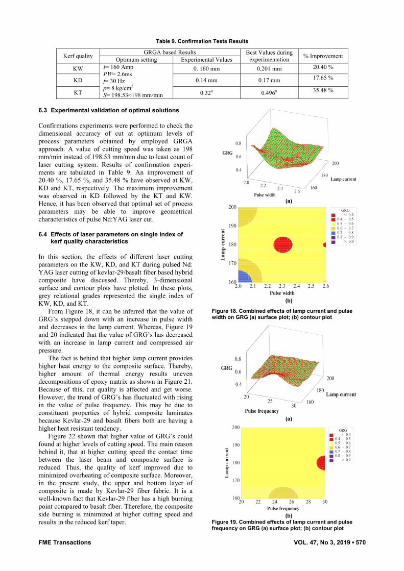
Table 9. Confirmation Tests Results
Kerf quality GRGA based Results Best Values during experimentation % Improvement Optimum setting Experimental Values
KW I= 160 Amp PW= 2.6ms f= 30 Hz p= 8 kg/cm2 S= 198.53≈198 mm/min
0. 160 mm 0.201 mm 20.40 %
KD 0.14 mm 0.17 mm 17.65 %
KT 0.32ο 0.496ο 35.48 %
6.3 Experimental validation of optimal solutions Confirmations experiments were performed to check the dimensional accuracy of cut at optimum levels of process parameters obtained by employed GRGA approach. A value of cutting speed was taken as 198 mm/min instead of 198.53 mm/min due to least count of laser cutting system. Results of confirmation experi-ments are tabulated in Table 9. An improvement of 20.40 %, 17.65 %, and 35.48 % have observed at KW, KD and KT, respectively. The maximum improvement was observed in KD followed by the KT and KW. Hence, it has been observed that optimal set of process parameters may be able to improve geometrical characteristics of pulse Nd:YAG laser cut. 6.4 Effects of laser parameters on single index of
kerf quality characteristics
In this section, the effects of different laser cutting parameters on the KW, KD, and KT during pulsed Nd: YAG laser cutting of kevlar-29/basalt fiber based hybrid composite have discussed. Thereby, 3-dimensional surface and contour plots have plotted. In these plots, grey relational grades represented the single index of KW, KD, and KT.
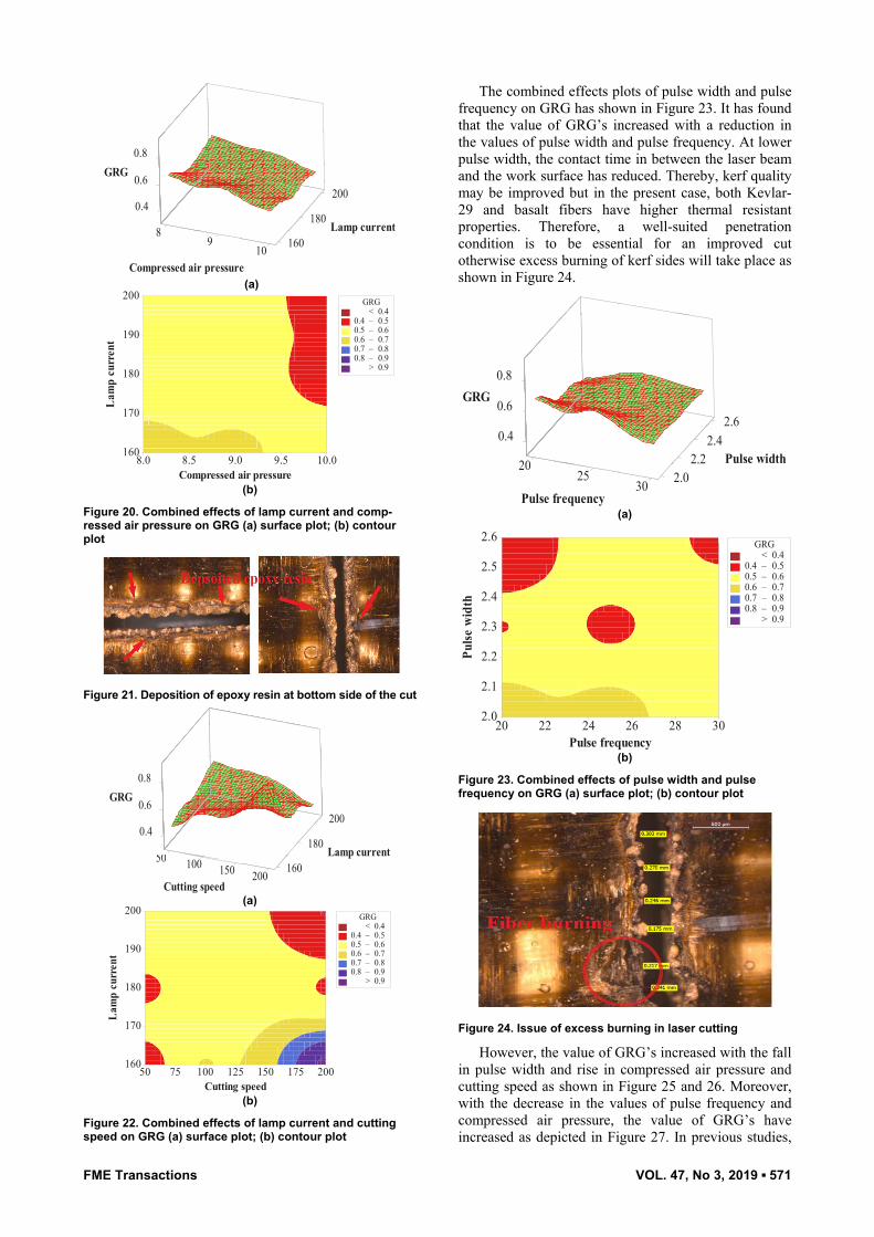
From Figure 18, it can be inferred that the value of GRG’s stepped down with an increase in pulse width and decreases in the lamp current. Whereas, Figure 19 and 20 indicated that the value of GRG’s has decreased with an increase in lamp current and compressed air pressure.
The fact is behind that higher lamp current provides higher heat energy to the composite surface. Thereby, higher amount of thermal energy results uneven decompositions of epoxy matrix as shown in Figure 21. Because of this, cut quality is affected and get worse. However, the trend of GRG’s has fluctuated with rising in the value of pulse frequency. This may be due to constituent properties of hybrid composite laminates because Kevlar-29 and basalt fibers both are having a higher heat resistant tendency.
Figure 22 shown that higher value of GRG’s could found at higher levels of cutting speed. The main reason behind it, that at higher cutting speed the contact time between the laser beam and composite surface is reduced. Thus, the quality of kerf improved due to minimized overheating of composite surface. Moreover, in the present study, the upper and bottom layer of composite is made by Kevlar-29 fiber fabric. It is a well-known fact that Kevlar-29 fiber has a high burning point compared to basalt fiber. Therefore, the composite side burning is minimized at higher cutting speed and results in the reduced kerf taper.
0.2 .2 2 .2 4
0.4
60.
1606.2
180
200
0.8
GRG
tnerruc pmaL
htdiw esluP (a)
Pulse width
Lam
p cu
rren
t
2.62.52.42.32.22.12.0
200
190
180
170
160
> – – – – – < 0.4
0.4 0.50.5 0.60.6 0.70.7 0.80.8 0.9
0.9
GRG
(b)
Figure 18. Combined effects of lamp current and pulse width on GRG (a) surface plot; (b) contour plot
0225
40.
.0 6
20206103
801
020
0 8.GRG
tnerruc pmaL
ycneuqerf esluP (a)
Pulse frequency
Lam
p cu
rren
t
302826242220
200
190
180
170
160
> – – – – – < 0.4
0.4 0.50.5 0.60.6 0.70.7 0.80.8 0.9
0.9
GRG
(b)
Figure 19. Combined effects of lamp current and pulse frequency on GRG (a) surface plot; (b) contour plot
FME Transactions VOL. 47, No 3, 2019 ▪ 571
89
4.0
0 6.
801601
180
200
0.8GRG
amp currentL
a desserpmo iC pressurer (a)
Compressed air pressure
Lam
p cu
rren
t
10.09.59.08.58.0
200
190
180
170
160
> – – – – – < 0.4
0.4 0.50.5 0.60.6 0.70.7 0.80.8 0.9
0.9
GRG
(b)
Figure 20. Combined effects of lamp current and comp-ressed air pressure on GRG (a) surface plot; (b) contour plot
Figure 21. Deposition of epoxy resin at bottom side of the cut
50 001 051
40.
.0 6
061002
81 0
200
80.GRG
tnerruc pmaL
deeps gnittuC (a)
Cutting speed
Lam
p cu
rren
t
2001751501251007550
200
190
180
170
160
> – – – – – < 0.4
0.4 0.50.5 0.60.6 0.70.7 0.80.8 0.9
0.9
GRG
(b)
Figure 22. Combined effects of lamp current and cutting speed on GRG (a) surface plot; (b) contour plot
The combined effects plots of pulse width and pulse frequency on GRG has shown in Figure 23. It has found that the value of GRG’s increased with a reduction in the values of pulse width and pulse frequency. At lower pulse width, the contact time in between the laser beam and the work surface has reduced. Thereby, kerf quality may be improved but in the present case, both Kevlar-29 and basalt fibers have higher thermal resistant properties. Therefore, a well-suited penetration condition is to be essential for an improved cut otherwise excess burning of kerf sides will take place as shown in Figure 24.
2025
.40
0.6
220 2.2.0203
4.22.2
2.64
0.8GRG
htdiw esluP
ycneuqerf esluP (a)
Pulse frequency
Pulse
wid
th
302826242220
2.6
2.5
2.4
2.3
2.2
2.1
2.0
> – – – – – < 0.4
0.4 0.50.5 0.60.6 0.70.7 0.80.8 0.9
0.9
GRG
(b)
Figure 23. Combined effects of pulse width and pulse frequency on GRG (a) surface plot; (b) contour plot
Figure 24. Issue of excess burning in laser cutting
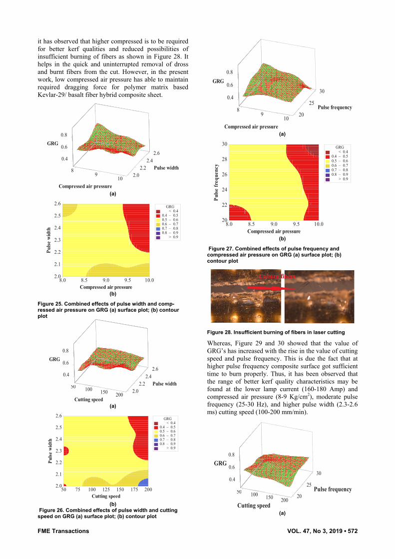
However, the value of GRG’s increased with the fall in pulse width and rise in compressed air pressure and cutting speed as shown in Figure 25 and 26. Moreover, with the decrease in the values of pulse frequency and compressed air pressure, the value of GRG’s have increased as depicted in Figure 27. In previous studies,
FME Transactions VOL. 47, No 3, 2019 ▪ 572
it has observed that higher compressed is to be required for better kerf qualities and reduced possibilities of insufficient burning of fibers as shown in Figure 28. It helps in the quick and uninterrupted removal of dross and burnt fibers from the cut. However, in the present work, low compressed air pressure has able to maintain required dragging force for polymer matrix based Kevlar-29/ basalt fiber hybrid composite sheet.
89
0 4.
0 6.
8 2.2.2 010
2 4.2.2
.624
0.8GRG
se widthluP
a desserpmo iC pressurer (a)
Compressed air pressure
Pulse
wid
th
10.09.59.08.58.0
2.6
2.5
2.4
2.3
2.2
2.1
2.0
> – – – – – < 0.4
0.4 0.50.5 0.60.6 0.70.7 0.80.8 0.9
0.9
GRG
(b)
Figure 25. Combined effects of pulse width and comp-ressed air pressure on GRG (a) surface plot; (b) contour plot
50 1 00 150
0.4
.0 6
22..02
020
2.422.
2.64
0.8GRG
htdiw esluP
deeps gnittuC (a)
Cutting speed
Pulse
wid
th
2001751501251007550
2.6
2.5
2.4
2.3
2.2
2.1
2.0
> – – – – – < 0.4
0.4 0.50.5 0.60.6 0.70.7 0.80.8 0.9
0.9
GRG
(b)
Figure 26. Combined effects of pulse width and cutting speed on GRG (a) surface plot; (b) contour plot
89
0 4.
6.0
802
01
52
30
80.GGR
s frluP e ycneuqe
erusserp ria deomprC ess (a)
Compressed air pressure
Pulse
freq
uenc
y10.09.59.08.58.0
30
28
26
24
22
20
> – – – – – < 0.4
0.4 0.50.5 0.60.6 0.70.7 0.80.8 0.9
0.9
GRG
(b)
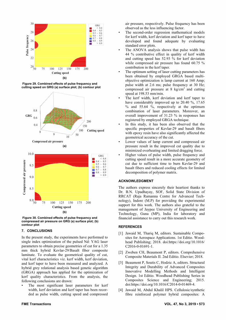
Figure 27. Combined effects of pulse frequency and compressed air pressure on GRG (a) surface plot; (b) contour plot
Figure 28. Insufficient burning of fibers in laser cutting
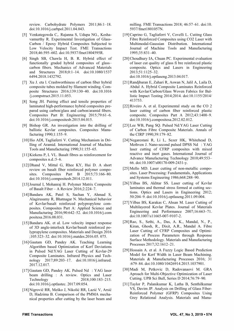
Whereas, Figure 29 and 30 showed that the value of GRG’s has increased with the rise in the value of cutting speed and pulse frequency. This is due the fact that at higher pulse frequency composite surface got sufficient time to burn properly. Thus, it has been observed that the range of better kerf quality characteristics may be found at the lower lamp current (160-180 Amp) and compressed air pressure (8-9 Kg/cm2), moderate pulse frequency (25-30 Hz), and higher pulse width (2.3-2.6 ms) cutting speed (100-200 mm/min).
05 001 150
0.4
.60
20002
25
03
0 8.GRG
ycneuqerf esluP
deeps gnittuC (a)
FME Transactions VOL. 47, No 3, 2019 ▪ 573
Cutting speed
Pulse
freq
uenc
y
2001751501251007550
30
28
26
24
22
20
> – – – – – < 0.4
0.4 0.50.5 0.60.6 0.70.7 0.80.8 0.9
0.9
GRG
(b)
Figure 29. Combined effects of pulse frequency and cutting speed on GRG (a) surface plot; (b) contour plot
89
40.
.0 6
8 1005001
51 0100
2 000
0 8.GRG
ng speedittuC
a desC erpmo ir pressures (a)
Cutting speed
Com
pres
sed
air p
ress
ure
2001751501251007550
10.0
9.5
9.0
8.5
8.0
> – – – – – < 0.4
0.4 0.50.5 0.60.6 0.70.7 0.80.8 0.9
0.9
GRG
(b)
Figure 30. Combined effects of pulse frequency and compressed air pressure on GRG (a) surface plot; (b) contour plot
7. CONCLUSIONS
In the present study, the experiments have performed to single index optimization of the pulsed Nd: YAG laser parameters to obtain precise geometries of cut for a 1.35 mm thick hybrid Kevlar-29/Basalt fiber composite laminate. To evaluate the geometrical quality of cut, vital kerf characteristics viz. kerf width, kerf deviation, and kerf taper to have been measured and analyzed. A hybrid grey relational analysis based genetic algorithm (GRGA) approach has applied for the optimization of kerf quality characteristics. From the analysis, the following conclusions are drawn: • The most significant laser parameters for kerf
width, kerf deviation and kerf taper has been recor-ded as pulse width, cutting speed and compressed
air pressure, respectively. Pulse frequency has been observed as the less influencing factor.
• The second-order regression mathematical models for kerf width, kerf deviation and kerf taper to have developed and found adequate by evaluating standard error plots.
• The ANOVA analysis shows that pulse width has 44 % contributive effect in quality of kerf width and cutting speed has 52.93 % for kerf deviation while compressed air pressure has found 60.75 % contribution in the kerf taper.
• The optimum setting of laser cutting parameters has been obtained by employed GRGA based multi-objective optimization is lamp current at 160 Amp; pulse width at 2.6 ms; pulse frequency at 30 Hz; compressed air pressure at 8 kg/cm2 and cutting speed at 198.53 mm/min.
• The kerf width, kerf deviation and kerf taper to have considerably improved up to 20.40 %, 17.65 % and 55.64 %, respectively at the optimum combination of laser parameters. Moreover, an overall improvement of 31.23 % in responses has registered by employed GRGA technique.
• In this study, it has been also observed that the specific properties of Kevlar-29 and basalt fibers with epoxy resin have also significantly affected the geometrical accuracy of the cut.
• Lower values of lamp current and compressed air pressure result in the improved cut quality due to minimized overheating and limited dragging force.
• Higher values of pulse width, pulse frequency and cutting speed result in a more accurate geometry of cut due to sufficient time to burn Kevlar-29 and basalt fibers and reduced cooling effects for limited decomposition of polymer matrix.
ACKNOWLEDGMENT
The authors express sincerely their heartiest thanks to Dr. B.N. Upadhayay, SOF, Solid State Division of RRCAT (Raja Ramanna Centre for Advanced Tech-nology), Indore (M.P) for providing the experimental support for this work. The authors also grateful to the management of Jaypee University of Engineering and Technology, Guna (MP), India for laboratory and financial assistance to carry out this research work.
REFERENCES
[1] Jawaid M, Thariq M, editors. Sustainable Compo-sites for Aerospace Applications. 1st Editio. Wood-head Publishing; 2018. doi:https://doi.org/10.1016/ C2016-0-01691-1.
[2] Zweben CH, Beaumont P, editors. Comprehensive Composite Materials II. 2nd Editio. Elsevier; 2018.
[3] Beaumont P, Soutis C, Hodzic A, editors. Structural Integrity and Durability of Advanced Composites Innovative Modelling Methods and Intelligent Design. 1st Editio. Woodhead Publishing Series in Composites Science and Engineering; 2015. doi:https://doi.org/10.1016/C2014-0-01469-4.
[4] Jawaid M, Abdul Khalil HPS. Cellulosic/synthetic fibre reinforced polymer hybrid composites: A
FME Transactions VOL. 47, No 3, 2019 ▪ 574
review. Carbohydrate Polymers 2011;86:1–18. doi:10.1016/j.carbpol.2011.04.043.
[5] Venkategowda C,. Rajanna S, Udupa NG., Kesha-vamurthy R. Experimental Investigation of Glass- Carbon / Epoxy Hybrid Composites Subjected to Low Velocity Impact Test. FME Transactions 2018;46:595–602. doi:10.5937/fmet1804595R.
[6] Singh SB, Chawla H, B. R. Hybrid effect of functionally graded hybrid composites of glass–carbon fibers. Mechanics of Advanced Materials and Structures 2018;0:1–14. doi:10.1080/1537 6494.2018.1432792.
[7] Xu J. eta l. Crashworthiness of carbon fiber hybrid composite tubes molded by filament winding. Com-posite Structures 2016;139:130–40. doi:10.1016 /j.compstruct.2015.11.053.
[8] Song JH. Pairing effect and tensile properties of laminated high-performance hybrid composites pre-pared using carbon/glass and carbon/aramid fibers. Composites Part B: Engineering 2015;79:61–6. doi:10.1016/j.compositesb.2015.04.015.
[9] Bishop GR. An investigation into the drilling of ballistic Kevlar composites. Composites Manu-facturing 1990;1:155–9.
[10] Ilio ADI, Tagliaferri V. Cutting Mechanism in Dri-lling of Aramid. International Journal of Machine Tools and Manufacturing 1990;31:155–65.
[11] Kiekens P, L VL. Basalt fibres as reinforcement for composites n.d.:5–6.
[12] Dhand V, Mittal G, Rhee KY, Hui D. A short review on basalt fiber reinforced polymer compo-sites. Composites Part B 2015;73:166–80. doi:10.1016/j.compositesb.2014.12.011.
[13] Journal I, Mohanraj H. Polymer Matrix Composite of Basalt Fiber – A Review 2016;2:224–7.
[14] Bandaru AK, Patel S, Sachan Y, Ahmad S, Alagirusamy R, Bhatnagar N. Mechanical behavior of Kevlar/basalt reinforced polypropylene com-posites. Composites Part A: Applied Science and Manufacturing 2016;90:642–52. doi:10.1016/j.com positesa.2016.08.031.
[15] Bandaru AK. et al. Low velocity impact response of 3D angle-interlock Kevlar/basalt reinforced po-lypropylene composites. Materials and Design 2016 ;105:323–32. doi:10.1016/j.matdes.2016.05. 075.
[16] Gautam GD, Pandey AK. Teaching Learning Algorithm based Optimization of Kerf Deviations in Pulsed Nd:YAG Laser Cutting of Kevlar-29 Composite Laminates. Infrared Physics and Tech-nology 2017;89:203–17. doi:10.1016/j.infrared. 2017.12.017.
[17] Gautam GD, Pandey AK. Pulsed Nd�: YAG laser beam drilling�: A review. Optics and Laser Technology 2018;100:183–215. doi:10.1016/j.optlastec. 2017.09.054.
[18] Nigrovič RR, Meško J, Nikolić RR, Lazić V, Arsić D, Hadzima B. Comparison of the PMMA mecha-nical properties after cutting by the laser beam and
milling. FME Transactions 2018; 46:57–61. doi:10. 5937/fmet1801057N.
[19] Caprino G, Tagliaferri V, Covelli L. Cutitng Glass Fibre Reinforced Composites using CO2 Laser with Multimodal-Gaussian Distribution. International Journal of Machine Tools and Manufacturing 1995;35:831–40.
[20] Choudhury IA, Chuan PC. Experimental evaluation of laser cut quality of glass fi bre reinforced plastic composite. Optics and Lasers in Engineering 2013;51:1125–32. doi:10.1016/j.optlaseng.2013.04.017.
[21] Randjbaran E, Zahari R, Aswan N, Jalil A, Laila D, Abdul A. Hybrid Composite Laminates Reinforced with Kevlar/Carbon/Glass Woven Fabrics for Bal-listic Impact Testing 2014;2014. doi:10.1155/2014/ 413753.
[22] Riveiro A. et al. Experimental study on the CO 2 laser cutting of carbon fiber reinforced plastic composite. Composites Part A 2012;43:1400–9. doi:10.1016/j.compositesa.2012.02.012.
[23] Lee WB, Pang SQ. Pulsed Nd:YAG Laser Cutting of Carbon Fibre Composite Materials. Annals of the CIRP 1990;39:179–82.
[24] Negarestani R, Li L, Sezer HK, Whitehead D, Methven J. Nano-second pulsed DPSS Nd�: YAG laser cutting of CFRP composites with mixed reactive and inert gases. International Journal of Advance Manufacturing Technology 2010;49:553–66. doi:10.1007/s00170-009-2431-y.
[25] Mello MD. Laser cutting of non-metallic compo-sites. Laser Processing: Fundamentals, Applications and Systems Engineering 1986;668:288–90.
[26] Yilbas BS, Akhtar SS. Laser cutting of Kevlar laminates and thermal stress formed at cutting sec-tions. Optics and Lasers in Engineering 2012; 50:204–9. doi:10.1016/j.optlaseng.2011.09.004.
[27] Yilbas BS, Karakas C, Ahsan M. Laser Cutting of Multilayered Kevlar Plates. Journal of Materials Engineering and Performance 2007;16:663–71. doi:10.1007/s11665-007-9107-2.
[28] Rao, S., Sethi, A., Das, A. K., Mandal, N., P., Kiran, Ghosh, R., Dixit, A.R., Mandal A. Fibre Laser Cutting of CFRP Composites and Optimi-zation of Process Parameters through Response Surface Methodology. Materials and Manufacturing Processes 2017;32:1612–21.
[29] Hossain A. et al. A Fuzzy Logic Based Prediction Model for Kerf Width in Laser Beam Machining. Materials & Manufacturing Processes 2016; 31 :679–84. doi:10.1080/10426914.2015.1037901.
[30] Madi M, Petkovic D, Radovanaovi M. GRA Aproach for Multi-Objective Optimization of Laser Cutting. UPB Sci Bull, Series D 2014;76:79–90.
[31] Taylor P, Palanikumar K, Latha B, Senthilkumar VS, Davim JP. Analysis on Drilling of Glass Fiber-Reinforced Polymer (GFRP) Composites Using Grey Relational Analysis. Materials and Manu-
FME Transactions VOL. 47, No 3, 2019 ▪ 575
facturing Processes 2012;27:297–305. doi:10.1080/ 10426914.2011.577865.
[32] Jang BZ et al. Impact resistance and energy absorption mechanisms in hybrid composites. Composites Science and Technology 1989;34:305–35. doi:10.1016/0266-3538(89)90002-X.
[33] Pandey AK, Gautam GD. Grey relational analysis-based genetic algorithm optimization of electrical discharge drilling of Nimonic-90 superalloy. Jour-nal of the Brazilian Society of Mechanical Sciences and Engineering 2018;40:1–16. doi:10.1007/ s40430-018-1045-4.
[34] Haq AN, Marimuthu P, Jeyapaul R. Multi response optimization of machining parameters of drilling Al / SiC metal matrix composite using grey relational analysis in the Taguchi method. International Journal of Advance Manufacturing Technology 2008;37:250–5. doi:10.1007/s00170-007-0981-4.
[35] Ivanov TD, Simonović AM, Svorcan JS, Peković OM. VAWT Optimization Using Genetic Algorithm and CST Airfoil Parameterization. FME Tran-sactions 2017;45:26–31. doi:10.5937/fmet1701026I.
ЕВАЛУАЦИЈА КВАЛИТЕТА ГЕОМЕТРИЈСКИХ КАРАКТЕРИСТИКА РЕЗАЊА ПУЛСНИМ Nd:YAG ЛАСЕРОМ
ХИБРИДНОГ КОМПОЗИТА ОЈАЧАНОГ KEVLAR-29/BASALT ВЛАКНИМА
ПРИМЕНОМ ГРЕЈОВЕ РЕЛАЦИОНЕ АНАЛИЗЕ БАЗИРАНЕ НА ГЕНЕТСКОМ
АЛГОРИТМУ
Г.Д. Гаутам, Д.Р. Мишра
Напредне технике обраде резањем ласером обез-беђују бољу контролу геометрије површине резања код композита ојачаних влакнима у поређењу са конвенционалним техникама резања захваљујући процесу у коме нема контакта и који је локализован. Међутим, перформансе резања ласером хибридних полимерних композита са ојачањем влакнима тек треба открити. У овом раду је приказано резање пулсним Nd:YAG ласером плоче дебљине 1,35 мм од композитног материјала oјачаног Kevlar-29/Basalt влакнима. Геометријска тачност је процењена мере-њем вредности ширине реза, одступања реза и конусности реза код 42 комбинације 5 параметара резања ласером: струја у лампи, ширина пулса, фреквенција пулса, притисак компримованог ваздуха и брзина резања. Интегрисани приступ бази-ран на Грејовој релационој анализи и генетском алгоритму коришћен је за оптимизацију поједи-начних параметара за различите типове квалитета реза. Утицај параметара такође се разматра у раду.