Embed Size (px)
Citation preview

September 10, 2002 8:38 WSPC/165-IJSSD 00059
International Journal of Structural Stability and DynamicsVol. 2, No. 3 (2002) 355–374c© World Scientific Publishing Company
EVALUATION OF DYNAMIC LOAD ON RAILTRACKSLEEPERS BASED ON VEHICLE-TRACK
MODELING AND ANALYSIS
G. KUMARAN∗, DEVDAS MENON† and K. KRISHNAN NAIR‡
Department of Civil Engineering, Indian Institute of Technology Madras,Chennai 600 036, India
∗[email protected]†[email protected]‡[email protected]
Received 22 April 2002Accepted 1 June 2002
The present study reports the results of a rigorous dynamic interaction analysis thataccounts for the vehicle-track characteristics and rail imperfections. In order to performa rigorous dynamic analysis, a model involving all components of the track structureand vehicle parameters are required. A vehicle model (conforming to Indian Railways)with 17 degrees of freedom has been considered. The track model consists of rail, rail-pad, sleeper, ballast, sub-ballast, subsoil and a track length encompassing 12 prestressedconcrete sleepers. The dynamic interactive analysis is carried out between the vehicle andtrack in the time domain using a finite element software. The results of the interactiveanalysis give responses in the form of reaction time histories at the rail-seat locationsduring the passage of vehicle. A parametric study is carried out to assess the influence ofdifferent track parameters on the dynamic load on the railtrack sleepers. Based on thisstudy, suitable load amplification factors are arrived at to facilitate an improved designbasis for an equivalent static analysis in practical designs of sleepers.
Keywords: Railtrack sleepers; dynamic analysis; vehicle model; track model; finiteelement analysis; track imperfections.
1. Introduction
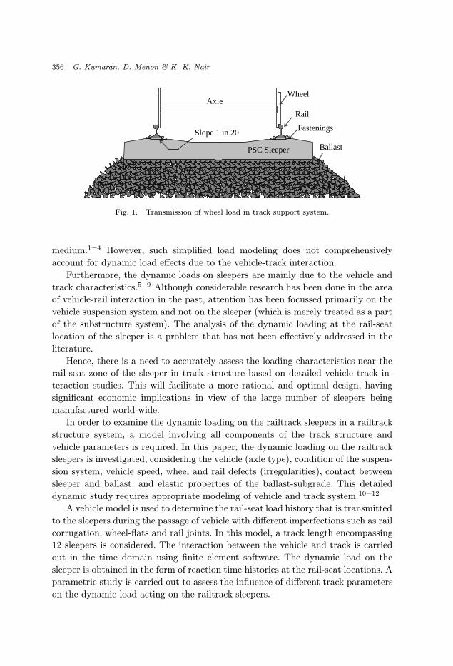
The railtrack structure system consists of the wheels, rails, rail-pads, fastenings,
sleepers, ballast and subgrade, cf. Fig. 1. In this track structure system, the load
transmission occurs, from the axle to the wheels, from wheels to rails, from rails
to sleepers, and finally from sleepers to the supporting ballast and subgrade. For
the purpose of design, railtrack seat loads are modeled as equivalent static loads
(including an “impact factor” for dynamic amplification derived empirically) equi-
librating with the ballast pressures provided by the underlying ballast-subgrade
∗Ph.D Research Scholar.†Associate Professor.‡M.S Research Scholar.
355
September 10, 2002 8:38 WSPC/165-IJSSD 00059
356 G. Kumaran, D. Menon & K. K. Nair
Wheel Axle
Ballast
Rail
Fastenings Slope 1 in 20
PSC Sleeper
Fig. 1. Transmission of wheel load in track support system.
medium.1–4 However, such simplified load modeling does not comprehensively
account for dynamic load effects due to the vehicle-track interaction.
Furthermore, the dynamic loads on sleepers are mainly due to the vehicle and
track characteristics.5–9 Although considerable research has been done in the area
of vehicle-rail interaction in the past, attention has been focussed primarily on the
vehicle suspension system and not on the sleeper (which is merely treated as a part
of the substructure system). The analysis of the dynamic loading at the rail-seat
location of the sleeper is a problem that has not been effectively addressed in the
literature.
Hence, there is a need to accurately assess the loading characteristics near the
rail-seat zone of the sleeper in track structure based on detailed vehicle track in-
teraction studies. This will facilitate a more rational and optimal design, having
significant economic implications in view of the large number of sleepers being
manufactured world-wide.
In order to examine the dynamic loading on the railtrack sleepers in a railtrack
structure system, a model involving all components of the track structure and
vehicle parameters is required. In this paper, the dynamic loading on the railtrack
sleepers is investigated, considering the vehicle (axle type), condition of the suspen-
sion system, vehicle speed, wheel and rail defects (irregularities), contact between
sleeper and ballast, and elastic properties of the ballast-subgrade. This detailed
dynamic study requires appropriate modeling of vehicle and track system.10–12
A vehicle model is used to determine the rail-seat load history that is transmitted
to the sleepers during the passage of vehicle with different imperfections such as rail
corrugation, wheel-flats and rail joints. In this model, a track length encompassing
12 sleepers is considered. The interaction between the vehicle and track is carried
out in the time domain using finite element software. The dynamic load on the
sleeper is obtained in the form of reaction time histories at the rail-seat locations. A
parametric study is carried out to assess the influence of different track parameters
on the dynamic load acting on the railtrack sleepers.
September 10, 2002 8:38 WSPC/165-IJSSD 00059
Dynamic Load of Railtrack Sleepers 357
The sleeper can be easily designed once the load on the sleeper is established
from the rigorous dynamic analysis, and this will provide a rational basis for
improved design recommendations.
2. Model of Railway Vehicle
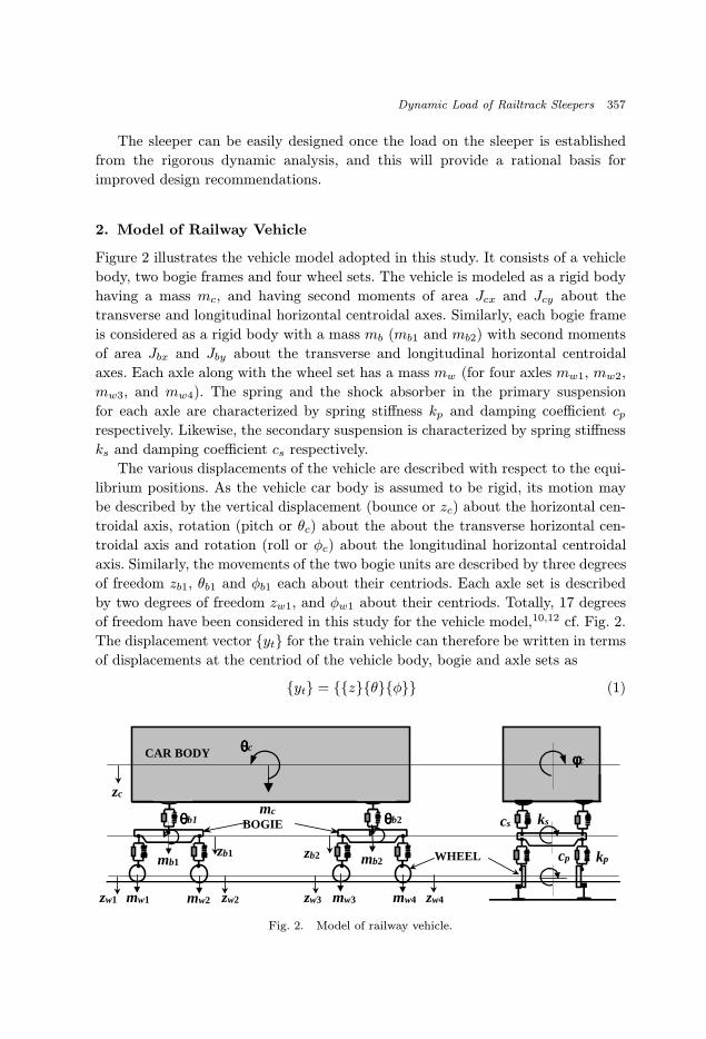
Figure 2 illustrates the vehicle model adopted in this study. It consists of a vehicle
body, two bogie frames and four wheel sets. The vehicle is modeled as a rigid body
having a mass mc, and having second moments of area Jcx and Jcy about the
transverse and longitudinal horizontal centroidal axes. Similarly, each bogie frame
is considered as a rigid body with a mass mb (mb1 and mb2) with second moments
of area Jbx and Jby about the transverse and longitudinal horizontal centroidal
axes. Each axle along with the wheel set has a mass mw (for four axles mw1, mw2,
mw3, and mw4). The spring and the shock absorber in the primary suspension
for each axle are characterized by spring stiffness kp and damping coefficient cprespectively. Likewise, the secondary suspension is characterized by spring stiffness
ks and damping coefficient cs respectively.
The various displacements of the vehicle are described with respect to the equi-
librium positions. As the vehicle car body is assumed to be rigid, its motion may
be described by the vertical displacement (bounce or zc) about the horizontal cen-
troidal axis, rotation (pitch or θc) about the about the transverse horizontal cen-
troidal axis and rotation (roll or φc) about the longitudinal horizontal centroidal
axis. Similarly, the movements of the two bogie units are described by three degrees
of freedom zb1, θb1 and φb1 each about their centriods. Each axle set is described
by two degrees of freedom zw1, and φw1 about their centriods. Totally, 17 degrees
of freedom have been considered in this study for the vehicle model,10,12 cf. Fig. 2.
The displacement vector {yt} for the train vehicle can therefore be written in terms
of displacements at the centriod of the vehicle body, bogie and axle sets as
{yt} = {{z}{θ}{φ}} (1)
θθθθc
mc
CAR BODY
BOGIE
WHEEL
φφφφc
ks
kpcp
csθθθθb1 θθθθb2
mb1 mb2
mw1 mw2 mw3 mw4
zb1 zb2
zc
zw1 zw2 zw3 zw4
Fig. 2. Model of railway vehicle.
September 10, 2002 8:38 WSPC/165-IJSSD 00059
358 G. Kumaran, D. Menon & K. K. Nair
where
{z} = {zc, zb1, zb2, zw1, zw2, zw3, zw4}; {θ} = {θc, θb1, θb2}
{φ} = {φc, φb1, φb2, φw1, φw2, φw3, φw4} .
The dynamic reactions at the left and right points on the rails are expressed in
terms of the dynamic reactive components WL1(t), WL2(t), WL3(t), WL4(t), and
WR1(t), WR2(t), WR3(t), WR4(t) respectively. Nonlinearities in the behaviour of
suspension the primary and secondary suspension units are not considered in this
present study.
The response is obtained when the vehicle traverses 12 sleeper bays of a model of
a railway track with constant speed. An initially straight track with imperfections
and without imperfections is considered. The vertical dynamic response of railtrack
sleeper excited under moving multi-axle loads on track structure is investigated. The
wheels of the train are assumed to have infinite stiffness. It is also assumed that
there is no loss of contact between the wheels of the vehicle and the rails. A Digital
Power FORTRAN subroutine has been written to perform dynamic analysis of the
vehicle effectively using direct integration technique.13 The equation of motion for
the vehicle model consisting of carbody, bogie units and wheel sets are derived
from rigid body idealization (detailed derivation is given in Appendix A) and can
be expressed as follows:
my + cy + ky = W(t) (2)
where m, c and k are the mass, damping and stiffness matrices of the vehicle
respectively and W(t) and y denote the load and displacement vectors respectively.
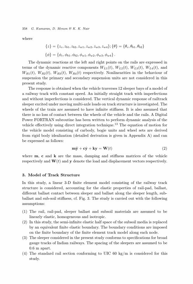
3. Model of Track Structure
In this study, a linear 3-D finite element model consisting of the railway track
structure is considered, accounting for the elastic properties of rail-pad, ballast,
different ballast contact between sleeper and ballast along the sleeper length, sub-
ballast and sub-soil stiffness, cf. Fig. 3. The study is carried out with the following
assumptions:
(1) The rail, rail-pad, sleeper ballast and subsoil materials are assumed to be
linearly elastic, homogeneous and isotropic.
(2) In this study, the semi-infinite elastic half space of the subsoil media is replaced
by an equivalent finite elastic boundary. The boundary conditions are imposed
on the finite boundary of the finite element track model along each node.
(3) The sleeper considered in the present study conforms to specifications for broad
gauge tracks of Indian railways. The spacing of the sleepers are assumed to be
0.6 m apart.
(4) The standard rail section conforming to UIC 60 kg/m is considered for this
study.
September 10, 2002 8:38 WSPC/165-IJSSD 00059
Dynamic Load of Railtrack Sleepers 359
Ballast
Rail
Boundaryconditions
Sleeper
Wheel loads
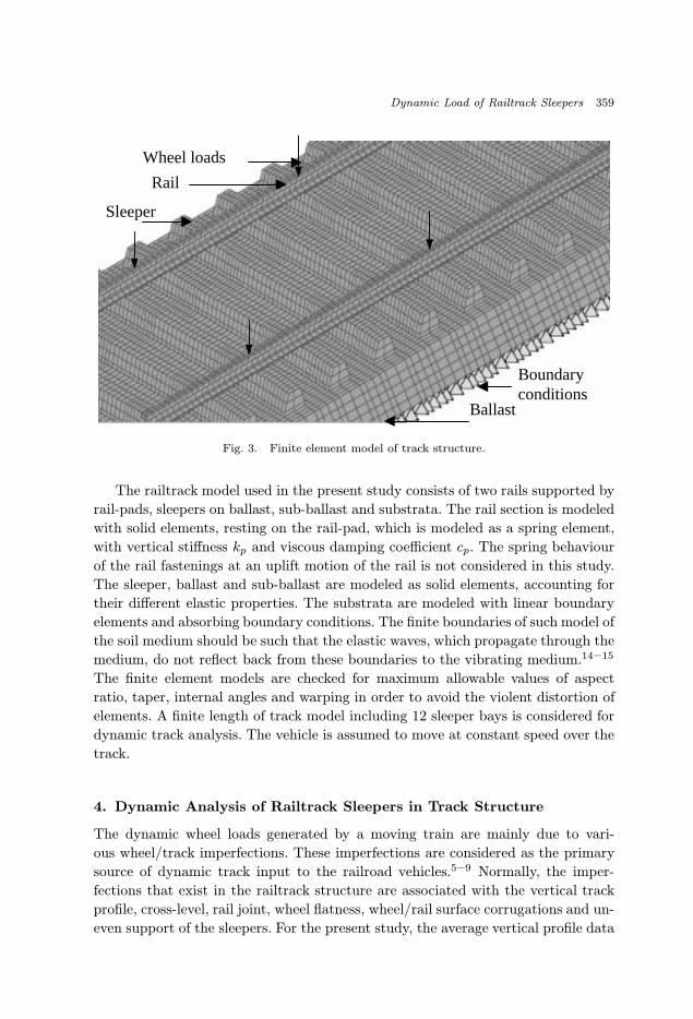
Fig. 3. Finite element model of track structure.
The railtrack model used in the present study consists of two rails supported by
rail-pads, sleepers on ballast, sub-ballast and substrata. The rail section is modeled
with solid elements, resting on the rail-pad, which is modeled as a spring element,
with vertical stiffness kp and viscous damping coefficient cp. The spring behaviour
of the rail fastenings at an uplift motion of the rail is not considered in this study.
The sleeper, ballast and sub-ballast are modeled as solid elements, accounting for
their different elastic properties. The substrata are modeled with linear boundary
elements and absorbing boundary conditions. The finite boundaries of such model of
the soil medium should be such that the elastic waves, which propagate through the
medium, do not reflect back from these boundaries to the vibrating medium.14–15
The finite element models are checked for maximum allowable values of aspect
ratio, taper, internal angles and warping in order to avoid the violent distortion of
elements. A finite length of track model including 12 sleeper bays is considered for
dynamic track analysis. The vehicle is assumed to move at constant speed over the
track.
4. Dynamic Analysis of Railtrack Sleepers in Track Structure
The dynamic wheel loads generated by a moving train are mainly due to vari-
ous wheel/track imperfections. These imperfections are considered as the primary
source of dynamic track input to the railroad vehicles.5–9 Normally, the imper-
fections that exist in the railtrack structure are associated with the vertical track
profile, cross-level, rail joint, wheel flatness, wheel/rail surface corrugations and un-
even support of the sleepers. For the present study, the average vertical profile data
September 10, 2002 8:38 WSPC/165-IJSSD 00059
360 G. Kumaran, D. Menon & K. K. Nair
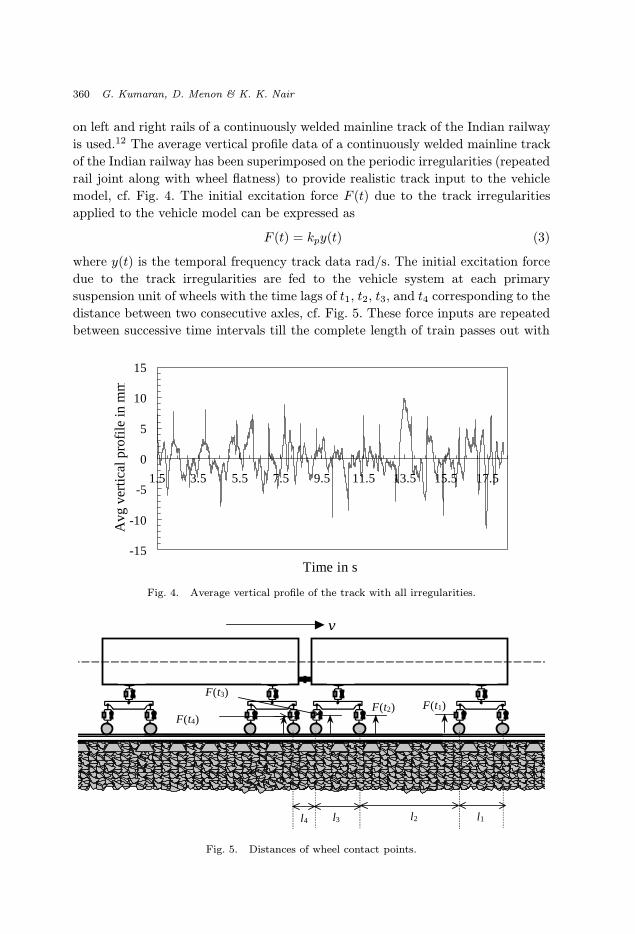
on left and right rails of a continuously welded mainline track of the Indian railway
is used.12 The average vertical profile data of a continuously welded mainline track
of the Indian railway has been superimposed on the periodic irregularities (repeated
rail joint along with wheel flatness) to provide realistic track input to the vehicle
model, cf. Fig. 4. The initial excitation force F (t) due to the track irregularities
applied to the vehicle model can be expressed as
F (t) = kpy(t) (3)
where y(t) is the temporal frequency track data rad/s. The initial excitation force
due to the track irregularities are fed to the vehicle system at each primary
suspension unit of wheels with the time lags of t1, t2, t3, and t4 corresponding to the
distance between two consecutive axles, cf. Fig. 5. These force inputs are repeated
between successive time intervals till the complete length of train passes out with
-15
-10
-5
0
5
10
15
1.5 3.5 5.5 7.5 9.5 11.5 13.5 15.5 17.5
Time in s
Avg
ver
tical
pro
file
in m
m
Fig. 4. Average vertical profile of the track with all irregularities.
v
F(t1)F(t3)
F(t4)
l1l2l4 l3
F(t2)
Fig. 5. Distances of wheel contact points.

September 10, 2002 8:38 WSPC/165-IJSSD 00059
Dynamic Load of Railtrack Sleepers 361
W(t)W(t)
ks
kpcp
cs
Fig. 6. Transmission of wheel load at the wheel-rail contact points.
Response fromvehicle model
Vehicle dynamics
Vertical vehicledynamics model
Track Input for vehicle modelTrack input to vehicle model
R(t) = kpy(t)
Track FEM Model
Checking the compatibilityconditions at the contactnodes between wheel and
track
If satisfied
Combined vehicle and track responses
Upd
ate
d v
alu
e o
f y (t )
Load history near the sleepers P(t)
Sleeper response to various train speeds
Not
Sat
isfie
d
Fig. 7. Flow chart illustrates the interaction between vehicle and track in time domain.
September 10, 2002 8:38 WSPC/165-IJSSD 00059
362 G. Kumaran, D. Menon & K. K. Nair
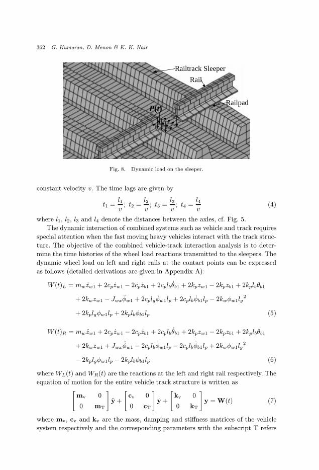
P(t)
Railtrack Sleeper
Rail
Railpad
Fig. 8. Dynamic load on the sleeper.
constant velocity v. The time lags are given by
t1 =l1
v; t2 =
l2
v; t3 =
l3
v; t4 =
l4
v(4)
where l1, l2, l3 and l4 denote the distances between the axles, cf. Fig. 5.
The dynamic interaction of combined systems such as vehicle and track requires
special attention when the fast moving heavy vehicles interact with the track struc-
ture. The objective of the combined vehicle-track interaction analysis is to deter-
mine the time histories of the wheel load reactions transmitted to the sleepers. The
dynamic wheel load on left and right rails at the contact points can be expressed
as follows (detailed derivations are given in Appendix A):
W (t)L = mw zw1 + 2cpzw1 − 2cpzb1 + 2cplbθb1 + 2kpzw1 − 2kpzb1 + 2kplbθb1
+ 2kwzw1 − Jwxφw1 + 2cplgφw1lp + 2cplbφb1lp − 2kwφw1lg2
+ 2kplgφw1lp + 2kplbφb1lp (5)
W (t)R = mw zw1 + 2cpzw1 − 2cpzb1 + 2cplbθb1 + 2kpzw1 − 2kpzb1 + 2kplbθb1
+ 2kwzw1 + Jwxφw1 − 2cplbφw1lp − 2cplbφb1lp + 2kwφw1lg2
− 2kplgφw1lp − 2kplbφb1lp (6)
where WL(t) and WR(t) are the reactions at the left and right rail respectively. The
equation of motion for the entire vehicle track structure is written as[mv 0
0 mT
]y +
[cv 0
0 cT
]y +
[kv 0
0 kT
]y = W(t) (7)
where mv, cv and kv are the mass, damping and stiffness matrices of the vehicle
system respectively and the corresponding parameters with the subscript T refers
September 10, 2002 8:38 WSPC/165-IJSSD 00059
Dynamic Load of Railtrack Sleepers 363
to the track system. The external force vector W(t) resulting from the wheel loads
is dependent on the wheel and track (rail) interaction, and hence is time-dependent.
The interaction between vehicle and track is solved numerically using the time
domain approach. In this study, a digital visual FORTRAN code is written to
calculate the vertical response of the vehicle by direct integration technique using
Newmark’s method. The free vibration analysis is carried out for the combined
vehicle and track system using MSC/NASTRAN software. The time steps for direct
integration are calculated from the natural frequency of the combined vehicle and
track system. The minimum time step to carry out the direct integration scheme
is taken as one-tenth of the fundamental time period, in the interest of numerical
stability.16 The dynamic wheel reaction from the vehicle model is fed to the 3-
D finite element track model. The compatibility conditions are satisfied at each
node and at each time step by considering the displacements of wheel and the
displacement of rail. Figure 7 illustrates vehicle-track interaction analysis in the
time domain.
5. Dynamic Load on Railtrack Sleeper
The dynamic wheel load from interaction analysis gets transmitted as reactive forces
on sleeper. The dynamic force on the railtrack sleeper is calculated as the sum of
the reaction forces obtained at the nodes of the finite element model, cf. Fig. 8. The
following relationship is used to determine the dynamic load history P (t) near the
rail-seat location:
P (t) = kp(zs − zr) + cp(zs − zr) (8)
where, kp and cp are the rail-pad stiffness and damping respectively; zr and zs are
the vertical displacements of the rail and the sleeper at the rail-seat locations respec-
tively and zr and zs are the vertical velocities of the rail and the sleeper respectively.
0
10000
20000
30000
40000
50000
60000
70000
0 0.5 1 1.5 2 2.5 3 3.5 4 4.5
Time in s
Dyn
amic
rai
l-se
at lo
ad in
N
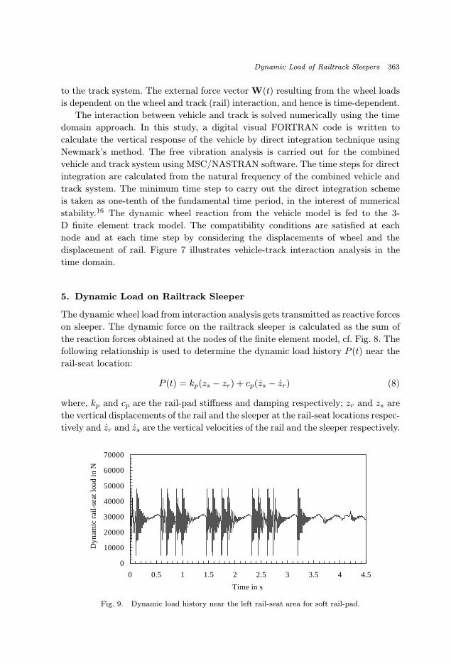
Fig. 9. Dynamic load history near the left rail-seat area for soft rail-pad.
September 10, 2002 8:38 WSPC/165-IJSSD 00059
364 G. Kumaran, D. Menon & K. K. Nair
0
10000
20000
30000
40000
50000
60000
70000
0 0.5 1 1.5 2 2.5 3 3.5 4 4.5
Time in s
Rai
lsea
t loa
d hi
stor
y in
N
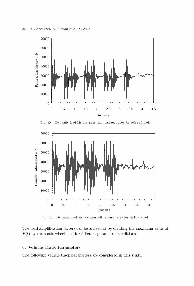
Fig. 10. Dynamic load history near right rail-seat area for soft rail-pad.
0
10000
20000
30000
40000
50000
60000
70000
0 0.5 1 1.5 2 2.5 3 3.5 4
Time in s
Dyn
amic
rai
l-sea
t loa
d in
N
Fig. 11. Dynamic load history near left rail-seat area for stiff rail-pad.
The load amplification factors can be arrived at by dividing the maximum value of
P (t) by the static wheel load for different parametric conditions.
6. Vehicle Track Parameters
The following vehicle track parameters are considered in this study.
September 10, 2002 8:38 WSPC/165-IJSSD 00059
Dynamic Load of Railtrack Sleepers 365
0
10000
20000
30000
40000
50000
60000
70000
0 0.5 1 1.5 2 2.5 3 3.5Time in s
Dyn
amic
rai
lsea
t loa
d in
N
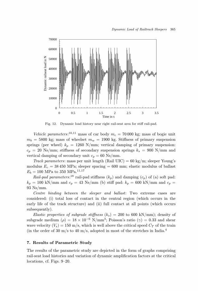
Fig. 12. Dynamic load history near right rail-seat area for stiff rail-pad.
Vehicle parameters :10,11 mass of car body mc = 70 000 kg; mass of bogie unit
mb = 5800 kg; mass of wheelset mw = 1900 kg. Stiffness of primary suspension
springs (per wheel) kp = 1260 N/mm; vertical damping of primary suspension:
cp = 20 Ns/mm; stiffness of secondary suspension springs ks = 900 N/mm and
vertical damping of secondary unit cp = 60 Ns/mm.
Track parameters: mass per unit length (Rail UIC) = 60 kg/m; sleeper Young’s
modulus Ec = 38 450 MPa; sleeper spacing = 600 mm; elastic modulus of ballast
Eb = 100 MPa to 350 MPa.11,17
Rail-pad parameters :18 rail-pad stiffness (kp) and damping (cp) of (a) soft pad:
kp = 100 kN/mm and cp = 43 Ns/mm (b) stiff pad: kp = 600 kN/mm and cp =
93 Ns/mm.
Centre binding between the sleeper and ballast : Two extreme cases are
considered: (i) total loss of contact in the central region (which occurs in the
early life of the track structure) and (ii) full contact at all points (which occurs
subsequently).
Elastic properties of subgrade stiffness (ks) = 200 to 600 kN/mm); density of
subgrade medium (ρ) = 18 × 10−6 N/mm3; Poisson’s ratio (γ) = 0.33 and shear
wave velocity (Vs) = 150 m/s, which is well above the critical speed CT of the train
(in the order of 30 m/s to 40 m/s, adopted in most of the stretches in India.4
7. Results of Parametric Study
The results of the parametric study are depicted in the form of graphs comprising
rail-seat load histories and variation of dynamic amplification factors at the critical
locations, cf. Figs. 9–20.
September 10, 2002 8:38 WSPC/165-IJSSD 00059
366 G. Kumaran, D. Menon & K. K. Nair
8. Summary and Conclusions
The dynamic load on the railtrack sleeper is studied based on the comprehensive
vehicle and track models. The vehicle considered in this study is modeled using
rigid body idealization with 17 degrees of freedom and the track is modeled using
finite element software with a track length encompassing 12 sleepers. The common
imperfections, viz. railjoints, wheel flatness and track unevenness have been consid-
ered for the dynamic input to the vehicle model. The dynamic analysis of vehicle
and track structure has been carried out numerically using finite element method
for different speeds and parametric conditions.
The time history plots of load response near the rail-seat, cf. Figs. 9–12, and the
dynamic amplification factors for different parametric conditions are investigated.
It is observed that the effect of different rail-pad stiffness is more significant than
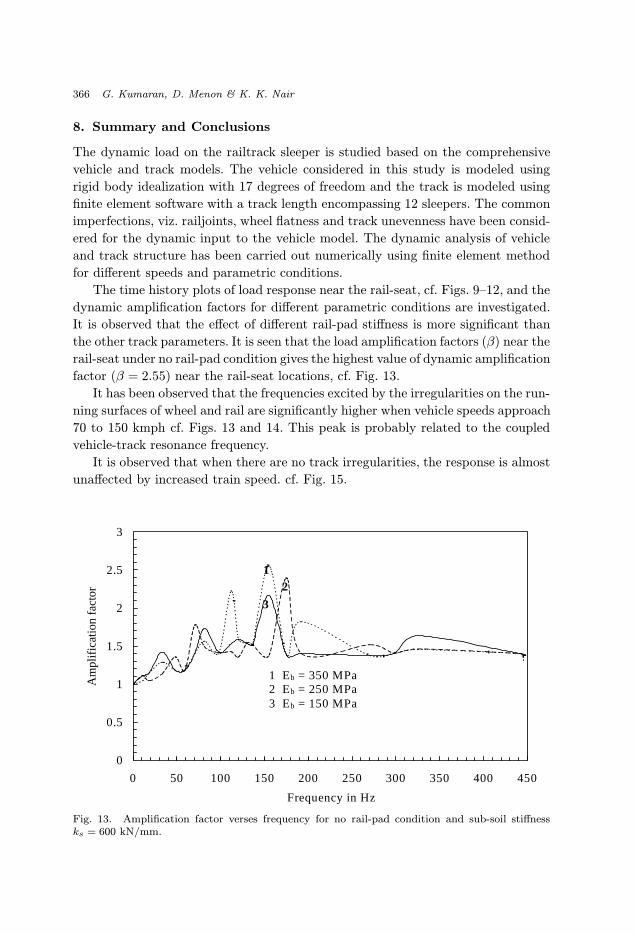
the other track parameters. It is seen that the load amplification factors (β) near the
rail-seat under no rail-pad condition gives the highest value of dynamic amplification
factor (β = 2.55) near the rail-seat locations, cf. Fig. 13.
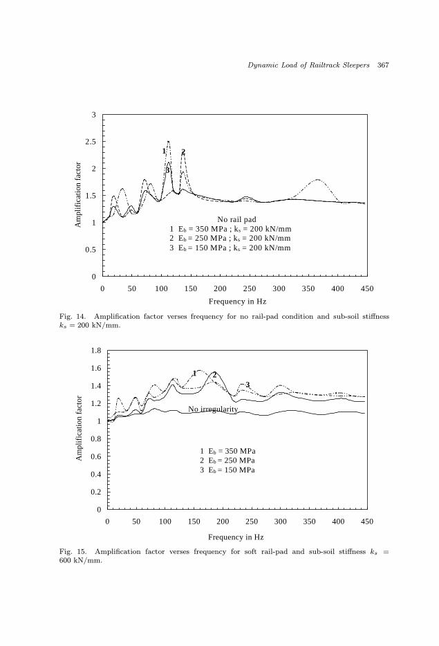
It has been observed that the frequencies excited by the irregularities on the run-
ning surfaces of wheel and rail are significantly higher when vehicle speeds approach
70 to 150 kmph cf. Figs. 13 and 14. This peak is probably related to the coupled
vehicle-track resonance frequency.
It is observed that when there are no track irregularities, the response is almost
unaffected by increased train speed. cf. Fig. 15.
0
0.5
1
1.5
2
2.5
3
0 50 100 150 200 250 300 350 400 450
Frequency in Hz
Am
plifi
catio
n fa
ctor
1 Eb = 350 MPa2 Eb = 250 MPa3 Eb = 150 MPa
1
3
2
Fig. 13. Amplification factor verses frequency for no rail-pad condition and sub-soil stiffnessks = 600 kN/mm.
September 10, 2002 8:38 WSPC/165-IJSSD 00059
Dynamic Load of Railtrack Sleepers 367
0
0.5
1
1.5
2
2.5
3
0 50 100 150 200 250 300 350 400 450
Frequency in Hz
Am
plifi
catio
n fa
ctor
No rail pad1 Eb = 350 MPa ; ks = 200 kN/mm2 Eb = 250 MPa ; ks = 200 kN/mm3 Eb = 150 MPa ; ks = 200 kN/mm
1
3
2
Fig. 14. Amplification factor verses frequency for no rail-pad condition and sub-soil stiffnessks = 200 kN/mm.
0
0.2
0.4
0.6
0.8
1
1.2
1.4
1.6
1.8
0 50 100 150 200 250 300 350 400 450
Frequency in Hz
Am
plifi
catio
n fa
ctor
321
No irregularity
1 Eb = 350 MPa2 Eb = 250 MPa3 Eb = 150 MPa
Fig. 15. Amplification factor verses frequency for soft rail-pad and sub-soil stiffness ks =600 kN/mm.
September 10, 2002 8:38 WSPC/165-IJSSD 00059
368 G. Kumaran, D. Menon & K. K. Nair
0
0.2
0.4
0.6
0.8
1
1.2
1.4
1.6
0 50 100 150 200 250 300 350 400 450
Frequency in Hz
Am
plifi
catio
n fa
ctor
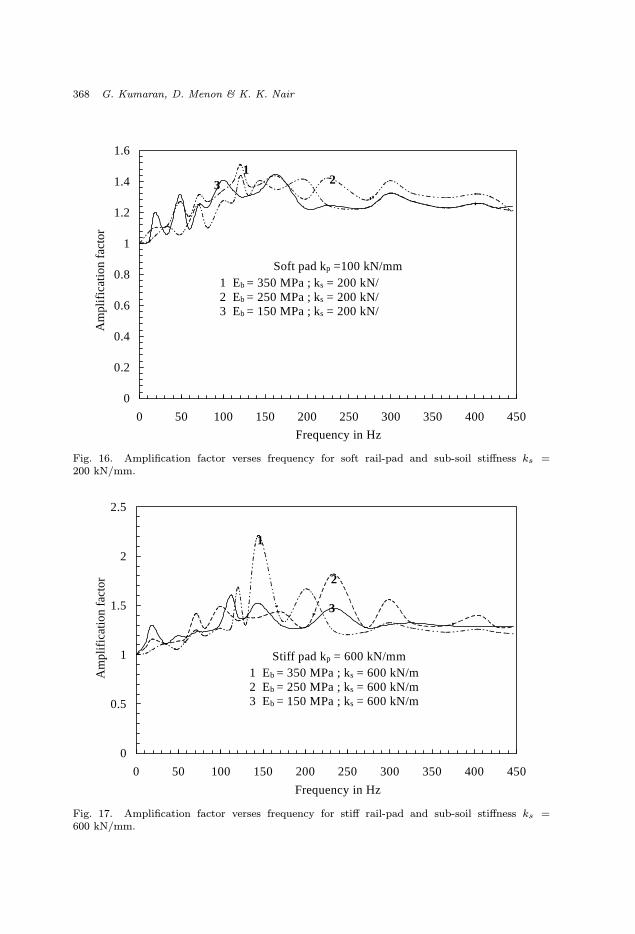
Soft pad kp =100 kN/mm1 Eb = 350 MPa ; ks = 200 kN/2 Eb = 250 MPa ; ks = 200 kN/3 Eb = 150 MPa ; ks = 200 kN/
13 2
Fig. 16. Amplification factor verses frequency for soft rail-pad and sub-soil stiffness ks =200 kN/mm.
0
0.5
1
1.5
2
2.5
0 50 100 150 200 250 300 350 400 450
Frequency in Hz
Am
plifi
catio
n fa
ctor
Stiff pad kp = 600 kN/mm1 Eb = 350 MPa ; ks = 600 kN/m2 Eb = 250 MPa ; ks = 600 kN/m3 Eb = 150 MPa ; ks = 600 kN/m
1
3
2
Fig. 17. Amplification factor verses frequency for stiff rail-pad and sub-soil stiffness ks =600 kN/mm.
September 10, 2002 8:38 WSPC/165-IJSSD 00059
Dynamic Load of Railtrack Sleepers 369
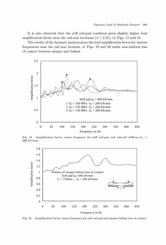
It is also observed that the stiff rail-pad condition gives slightly higher load
amplification factor near the rail-seat locations (β = 2.21), cf. Figs. 17 and 18.
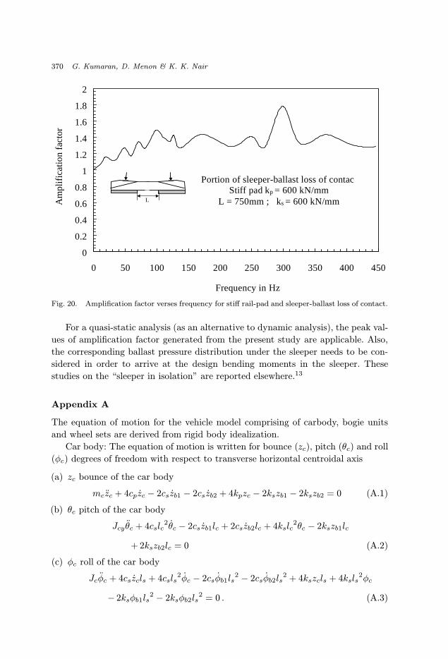
The results of the dynamic analysis gives the load amplification factor for various
frequencies near the rail seat location, cf. Figs. 19 and 20 under non-uniform loss
of contact between sleeper and ballast.
0
0.5
1
1.5
2
2.5
0 50 100 150 200 250 300 350 400 450
Frequency in Hz
Am
plifi
catio
n fa
ctor
Stiff pad kp = 600 kN/mm1 Eb = 350 MPa ; ks = 200 kN/mm2 Eb = 250 MPa ; ks = 200 kN/mm3 Eb = 150 MPa ; ks = 200 kN/mm
1
32
Fig. 18. Amplification factor verses frequency for stiff rail-pad and sub-soil stiffness ks =200 kN/mm.
0
0.2
0.4
0.6
0.8
1
1.2
1.4
1.6
1.8
0 50 100 150 200 250 300 350 400 450
Frequency in Hz
Am
plifi
catio
n fa
ctor
Portion of sleeper-ballast loss of contactSoft pad kp=100 kN/mm
L = 750mm ; ks = 200 kN/mm
L
Fig. 19. Amplification factor verses frequency for soft rail-pad and sleeper-ballast loss of contact.
September 10, 2002 8:38 WSPC/165-IJSSD 00059
370 G. Kumaran, D. Menon & K. K. Nair
0
0.2
0.4
0.6
0.8
1
1.2
1.4
1.6
1.8
2
0 50 100 150 200 250 300 350 400 450
Frequency in Hz
Am
plifi
catio
n fa
ctor
Portion of sleeper-ballast loss of contacStiff pad kp = 600 kN/mm
L = 750mm ; ks = 600 kN/mmL
Fig. 20. Amplification factor verses frequency for stiff rail-pad and sleeper-ballast loss of contact.
For a quasi-static analysis (as an alternative to dynamic analysis), the peak val-
ues of amplification factor generated from the present study are applicable. Also,
the corresponding ballast pressure distribution under the sleeper needs to be con-
sidered in order to arrive at the design bending moments in the sleeper. These
studies on the “sleeper in isolation” are reported elsewhere.13
Appendix A
The equation of motion for the vehicle model comprising of carbody, bogie units
and wheel sets are derived from rigid body idealization.
Car body: The equation of motion is written for bounce (zc), pitch (θc) and roll
(φc) degrees of freedom with respect to transverse horizontal centroidal axis
(a) zc bounce of the car body
mczc + 4cpzc − 2cszb1 − 2cszb2 + 4kpzc − 2kszb1 − 2kszb2 = 0 (A.1)
(b) θc pitch of the car body
Jcy θc + 4cslc2θc − 2cszb1lc + 2cszb2lc + 4kslc
2θc − 2kszb1lc
+ 2kszb2lc = 0 (A.2)
(c) φc roll of the car body
Jcφc + 4cszcls + 4csls2φc − 2csφb1ls
2 − 2csφb2ls2 + 4kszcls + 4ksls
2φc
− 2ksφb1ls2 − 2ksφb2ls
2 = 0 . (A.3)
September 10, 2002 8:38 WSPC/165-IJSSD 00059
Dynamic Load of Railtrack Sleepers 371
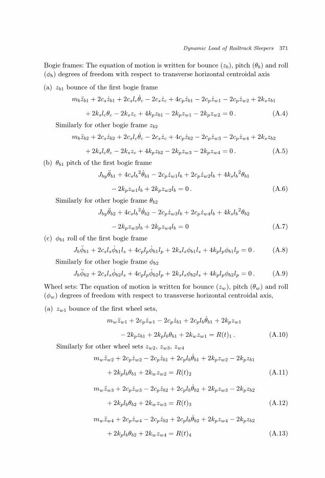
Bogie frames: The equation of motion is written for bounce (zb), pitch (θb) and roll
(φb) degrees of freedom with respect to transverse horizontal centroidal axis
(a) zb1 bounce of the first bogie frame
mbzb1 + 2cszb1 + 2cslcθc − 2cszc + 4cpzb1 − 2cpzw1 − 2cpzw2 + 2kszb1
+ 2kslcθc − 2kszc + 4kpzb1 − 2kpzw1 − 2kpzw2 = 0 . (A.4)
Similarly for other bogie frame zb2
mbzb2 + 2cszb2 + 2cslcθc − 2cszc + 4cpzb2 − 2cpzw3 − 2cpzw4 + 2kszb2
+ 2kslcθc − 2kszc + 4kpzb2 − 2kpzw3 − 2kpzw4 = 0 . (A.5)
(b) θb1 pitch of the first bogie frame
Jby θb1 + 4cslb2θb1 − 2cpzw1lb + 2cpzw2lb + 4kslb
2θb1
− 2kpzw1lb + 2kpzw2lb = 0 . (A.6)
Similarly for other bogie frame θb2
Jby θb2 + 4cslb2θb2 − 2cpzw3lb + 2cpzw4lb + 4kslb
2θb2
− 2kpzw3lb + 2kpzw4lb = 0 (A.7)
(c) φb1 roll of the first bogie frame
Jbφb1 + 2cslsφb1ls + 4cplpφb1lp + 2kslsφb1ls + 4kplpφb1lp = 0 . (A.8)
Similarly for other bogie frame φb2
Jbφb2 + 2cslsφb2ls + 4cplpφb2lp + 2kslsφb2ls + 4kplpφb2lp = 0 . (A.9)
Wheel sets: The equation of motion is written for bounce (zw), pitch (θw) and roll
(φw) degrees of freedom with respect to transverse horizontal centroidal axis,
(a) zw1 bounce of the first wheel sets,
mw zw1 + 2cpzw1 − 2cpzb1 + 2cplbθb1 + 2kpzw1
− 2kpzb1 + 2kplbθb1 + 2kwzw1 = R(t)1 . (A.10)
Similarly for other wheel sets zw2, zw3, zw4
mwzw2 + 2cpzw2 − 2cpzb1 + 2cplbθb1 + 2kpzw2 − 2kpzb1
+ 2kplbθb1 + 2kwzw2 = R(t)2 (A.11)
mwzw3 + 2cpzw3 − 2cpzb2 + 2cplbθb2 + 2kpzw3 − 2kpzb2
+ 2kplbθb2 + 2kwzw3 = R(t)3 (A.12)
mwzw4 + 2cpzw4 − 2cpzb2 + 2cplbθb2 + 2kpzw4 − 2kpzb2
+ 2kplbθb2 + 2kwzw4 = R(t)4 (A.13)
September 10, 2002 8:38 WSPC/165-IJSSD 00059
372 G. Kumaran, D. Menon & K. K. Nair
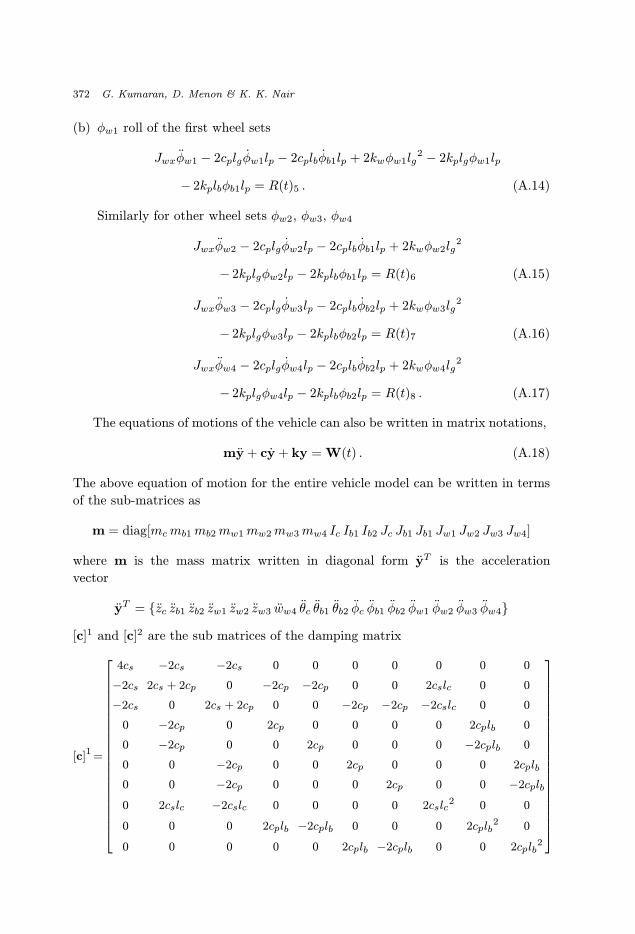
(b) φw1 roll of the first wheel sets
Jwxφw1 − 2cplgφw1lp − 2cplbφb1lp + 2kwφw1lg2 − 2kplgφw1lp
− 2kplbφb1lp = R(t)5 . (A.14)
Similarly for other wheel sets φw2, φw3, φw4
Jwxφw2 − 2cplgφw2lp − 2cplbφb1lp + 2kwφw2lg2
− 2kplgφw2lp − 2kplbφb1lp = R(t)6 (A.15)
Jwxφw3 − 2cplgφw3lp − 2cplbφb2lp + 2kwφw3lg2
− 2kplgφw3lp − 2kplbφb2lp = R(t)7 (A.16)
Jwxφw4 − 2cplgφw4lp − 2cplbφb2lp + 2kwφw4lg2
− 2kplgφw4lp − 2kplbφb2lp = R(t)8 . (A.17)
The equations of motions of the vehicle can also be written in matrix notations,
my + cy + ky = W(t) . (A.18)
The above equation of motion for the entire vehicle model can be written in terms
of the sub-matrices as
m = diag[mcmb1mb2mw1mw2mw3mw4 Ic Ib1 Ib2 Jc Jb1 Jb1 Jw1 Jw2 Jw3 Jw4]
where m is the mass matrix written in diagonal form yT is the acceleration
vector
yT = {zc zb1 zb2 zw1 zw2 zw3 ww4 θc θb1 θb2 φc φb1 φb2 φw1 φw2 φw3 φw4}
[c]1 and [c]2 are the sub matrices of the damping matrix
[c]1 =
4cs −2cs −2cs 0 0 0 0 0 0 0
−2cs 2cs + 2cp 0 −2cp −2cp 0 0 2cslc 0 0
−2cs 0 2cs + 2cp 0 0 −2cp −2cp −2cslc 0 0
0 −2cp 0 2cp 0 0 0 0 2cplb 0
0 −2cp 0 0 2cp 0 0 0 −2cplb 0
0 0 −2cp 0 0 2cp 0 0 0 2cplb
0 0 −2cp 0 0 0 2cp 0 0 −2cplb
0 2cslc −2cslc 0 0 0 0 2cslc2 0 0
0 0 0 2cplb −2cplb 0 0 0 2cplb2 0
0 0 0 0 0 2cplb −2cplb 0 0 2cplb2
September 10, 2002 8:38 WSPC/165-IJSSD 00059
Dynamic Load of Railtrack Sleepers 373
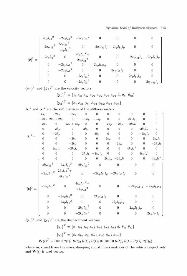
[c]2 =
4cslc12 −2cslc1
2 −2cslc12 0 0 0 0
−2cslc12 2cslc1
2+
4cplb12
0 −2cplb1lg −2cplb1lg 0 0
−2cslcl2 0
2cslc12+
2cplb12
0 0 −2cplb1lg −2cplb1lg
0 −2cplb12 0 2cplb1lg 0 0 0
0 −2cplb12 0 0 2cplb1lg 0 0
0 0 −2cplb12 0 0 2cplb1lg 0
0 0 −2cplb12 0 0 0 2cplb1lg
{y1}T and {y2}T are the velocity vectors
{y1}T = {zc zb1 zb2 zw1 zw2 zw3 zw4 θc θb1 θb2}
{y2}T = {φc φb1 φb1 φw1 φw2 φw3 φw4}[k]1 and [k]2 are the sub matrices of the stiffness matrix
[k]1 =
4ks −2ks −2ks 0 0 0 0 0 0 0
−2ks 2ks + 2kp 0 −2kp −2kp 0 0 2kslc 0 0
−2ks 0 2ks + 4kp 0 0 −2kp −2kp −2kslc 0 0
0 −2kp 0 2kp 0 0 0 0 2kplb 0
0 −2kp 0 0 2kp 0 0 0 −2kplb 0
0 0 −2kp 0 0 2kp 0 0 0 2kplb
0 0 −2kp 0 0 0 2kp 0 0 −2kplb
0 2kslc −2kslc 0 0 0 0 4kslc2 0 0
0 0 0 2kplb −2kplb 0 0 0 4kplb2 0
0 0 0 0 0 2kplb −2kplb 0 0 4kplb2
[k]2 =
4kslc12 −2kslc1
2 −2kslc12 0 0 0 0
−2kslc12 2kslc1
2+
4kplb12
0 −2kplb1lg −2kplb1lg 0 0
−2kslc12 0
4kslc12+
2kplb12
0 0 −2kplb1lg −2kplb1lg
0 −2kplb12 0 2kplb1lg 0 0 0
0 −2kplb12 0 0 2kplb1lg 0 0
0 0 −2kplb12 0 0 2kplb1lg 0
0 0 −2kplb12 0 0 0 2kplb1lg
{y1}T and {y2}T are the displacement vectors
{y1}T = {zc zb1 zb2 zw1 zw2 zw3 zw4 θc θb1 θb2}
{y2}T = {φc φb1 φb1 φw1 φw2 φw3 φw4}
W(t)T = {0 0 0R(t)1R(t)2R(t)3R(t)4 0 0 0 0 0 0R(t)5R(t)6R(t)7R(t)8}where m, c and k are the mass, damping and stiffness matrices of the vehicle respectivelyand W(t) is load vector.
September 10, 2002 8:38 WSPC/165-IJSSD 00059
374 G. Kumaran, D. Menon & K. K. Nair
References
1. A. N. Talbot, Stresses in Railroad Track — Reports of the Special Committee onStresses in Railroad Track, Seven Progress Reports, American Railway Engineeringand Maintenance of Way Association, AREMA, 1934.
2. H. P. J. Taylor, “The prestressed concrete railway sleepers — 50 Years of pretensioned,prestressed concrete,” J. Struct. Eng. 71, pp. 281–289, 1993.
3. H. E. Stewart and D. O’Rourke, “Load factor method for dynamic track loading,” J.Transport. Eng. ASCE 114, pp. 21–39, 1998.
4. Standard Specification for Pretensioned Concrete Sleepers, RDSO, Third Revision,Indian Railways, Lucknow, 1996.
5. S. L. Grassie and S. J. Cox, “The dynamic response of railway track with flexiblesleepers to high frequency vertical excitation,” Proc. Inst. Mech. Eng. D198, pp. 117–124, 1983.
6. K. L. Knothe and S. L. Grassie, “Railway track and vehicle/track interaction,”J. Vehicles Syst. Dynam. 22, 217–262, 1993.
7. J. C. O. Nielsen, “Vertical dynamic interaction between train and track — Influenceof wheel and track imperfections,” J. Sound Vib. 87(5), pp. 825–839, 1995.
8. Y. B. Yang and J. D. Yau, “Vehicle-bridge interaction element for dynamic analysis,”J. Struct. Eng. ASCE 123(11), pp. 1512–1518, 1997.
9. Y. S. Wu., Y. B. Yang and J. D. Yau, “Three-dimensional analysis of train-rail-bridgeinteraction problems,” Vehicle Syst. Dynam. J. Vehicle Mech. Mob. 36(1), pp. 1–35,2001.
10. V. Dukkipati and J. R. Amyot, Computer-Aided Simulation in Railway Dynamics,Marcel Dekker Inc., New York, 1988.
11. C. S. Desai and A. M. Siriwardane, “Numerical models for track support structures,”J. Geotech. Eng. Div. ASCE 108, pp. 461–480, 1982.
12. K. V. Gangadharan, “Analytical and experimental studies on dynamics of rail-road vehicles,” PhD Thesis, Department of Applied Mechanics, Indian Institute ofTechnology Madras, 2001.
13. G. Kumaran, D. Menon and K. K. Nair, “Dynamic response of railtrack sleepers tomoving loads,” Proc. EURODYN 2002 (In print).
14. P. Wolf, Foundation Vibration Analysis using Simple Physical Models, Prentice-Hall,Englewood Cliffs, New Jersey, 1994.
15. J. Dinkel and H. Grundmann, “Winkler parameters for railway dynamics derived from3-D half space analysis,” Proc. Struct. Dynam. — EURODYN 99, pp. 831–836, 1999.
16. A. K. Chopra, Dynamics of Structures Theory and Applications to Earthquake Engi-neering Prentice-Hall, Pearson Education Co., New Jersey, 2001.
17. D. Li and T. Ernest, “Wheel/track dynamic interaction — Track substructureperspective,” J. Vehicle Syst. Dynam. 24, pp. 183–196, 1995.
18. B. Ripke and K. Knothe, “Simulation of high frequency vehicle-track interactions,”J. Vehicle Syst. Dynam. 24(Suppl.), pp. 72–85, 1995.