Embed Size (px)
Citation preview

TECHNICAL REPORT NATICK/ TR-88/023
AD __ ~--
~ EVALUATION OF DESIGN CONCEPTS ·.· FOR TENTS WITH
CW PROTECTION REQUIREMENTS
BY
EARL C. STEEVES .
SEPTEMBER 1987 FlNAL REPORT
OCTOBER 1982-SEPTEMBER 1985
I I \
APPROVED FOR PUBLIC RELEASE; DISTRIBUTION UNLIMITED .
I
, .
UNITED STATES ARMY NATICK . I
RESEARCH, DEVELOPMENT AND ENGINEERING CENTER NATICK, MASSACHUSETTS 01760-5000
AERO-MECHANICAL ENGINEERING DIRECTORATE ·'
I . .

I DISCLAIMERS
The findings contained in this report are not to
be construed as an official Department of the Army
position unless so designated by other authori~ed
documents.
Citation of trade names in this report does not
constitute an official endorsement or approval of
the use of such items.
r·
DESTRUCTION NOTICE
For Classified Documents:
Follow the procedures in DoD 5200.22-M, Industrial
Security Manual, Section II-19 or DoD 5200.1-R,
Information Security Program Regulation, Chapter IX.
For Unclassified/Limited Distribution Documents:
Destroy by any method that prevents disclosure of
contents or reconstruction of the document.
I
' I ~ i

UNCLASSIFIED SECURITY CLASSIFICATION OF THIS PAGE
REPORT DOCUMENTATION PAGE Form Approved OMB No 0704-0188 Exp_ Date: Jun 30, 1986
1a. REPORT SECURITY CLASSIFICATION 1 b. RESTRICTIVE MARKINGS
UNCLASSIFIED 2a. SECURITY CLASSIFICATION AUTHORITY 3. DISTRIBUTION I AVAILABILITY OF REPORT
2b. DECLASSIFICATION I DOWNGRADING SCHEDULE Approved for Public Release; Distribution Unlimited.
4. PERFORMING ORGANIZATION REPORT NUMBER(S) S. MONITORING ORGANIZATION REPORT NUMBER(S)
NAT!CK/TR-\2'2/ o?.S
6a. NAME OF PERFORMING ORGANIZATION 6b. OFFICE SYMBOL 7a. NAME OF MONITORING ORGANIZATION (If applicable)
U.S. Army Natick RD&E Center STRNC-UE 6c. ADDRESS (City, State, and ZIP Code) 7b. ADDRESS (City, State, and ZIP Code)
ATTN: STRNC-UE Natick, MA 01760-5017
Ba. NAME OF FUNDING/SPONSORING Bb. OFFICE SYMBOL 9. PROCUREMENT INSTRUMENT IDENTIFICATION NUMBER ORGANIZATION (If applicable)
Sc. ADDRESS (City, State, and ZIP Code) 10. SOURCE OF FUNDING NUMBERS
PROGRAM PROJECT TASK WORK UNIT ELEMENT NO. NO. NO. ACCESSION NO.
1Ll62723 AH98 AE 056 11. TITLE (Include Security Classification)
Evaluation of Design Concepts for Tents With Cli Protection Requirements 12. PERSONAL AUTHOR(S)
Earl c. Steeves 13a. TYPE OF REPORT 113b. TIME COVERED 14. DATE OF REPORT (Year, Month, Day) . r 5. PAGE COUNT
Fi na 1 FROM l OL82 TO 9L85 1987 September 16. SUPPLEMENTARY NOTATION
17. COSATI CODES 18. SUBJECT TERMS (Continue on reverse if necessary and identify by block number)
FIELD GROUP SUB-GROUP Tents, shelters, concepts, evaluation, collective protection, chemical protection
19. ABSTRACT (Continue on reverse if necessary and identify by block number)
The implementation of the analytic hierarchy process (as described by T.L. Saaty) for the evaluation of tent design concepts is described. A hierarchy made up of the following four levels is used: function to be sheltered, operational factors, design requirements and alternative design concepts. The evaluation was performed by a team of tentage experts in the development community. Instead of considering complete tent concepts, the evaluation was performed on alternative design concepts for the structural support, barrier material and chemica 1 protection components of a tent. The eva 1 uati on found that the most acceptable concepts are the pressurized rib concept for structural support, the laminated fabric film for the barrier material and the integrated environmental/chemical barrier for chemical protection.
20. DISTRIBUTION I AVAILABILITY OF ABSTRACT 21. ABSTRACT SECURITY CLASSIFICATION
IXJ UNCLASSIFIEO/UNLIMITED 0 SAME AS RPT. D OTIC USERS UNCLASSIFIED 22a. NAME OF RESPONSIBLE INDIVIDUAL 22b. TELEPHONE (Include Area Code) 22c. OFFICE SYMBOL
Ear 1 c. Steeves ( 617) 651-5266 STRNC-UE DO FORM 1473,84 MAR 83 APR edition may be used untd exhausted. SECURITY CLASSIFICATION OF THIS PAGE
All other editions are obsolete. UNCLASSIFIED i

i i

SUMMARY
An evaluation of design concepts for tents with chemical warfare (CW) protection requirements has been completed for eight generalized Army functions. The evaluation was carried out using the analytic hierarchy process, which gives a quantitative measure of relative merit. The report illustrates the use of the analytic hierarchy process through the use of a scaled-down hierarchy for tent design, describes the complete hierarchy for tent design, and gives results obtained using this process for the complete hierarchy. Instead of evaluating complete tent designs, alternative concepts for the structural support, barrier material, and chemical protection components are evaluated. The results recommend the following for further development: The pressurized rib concept for structural support with the frame concept as a backup; the laminated fabric/film for the barrier material; and an integral environmental/chemical barrier for chemical protection. The laminated fabric/film is a barrier material that has the environmental and chemical barrier integrated or combined. In the development of this one concept the requirements for two components are satisfied. These recommendations are especially applicable to the battalion aid station because a set of requirements for that item was used in the evaluation.
The process used here for the evaluation of tentage components is sufficiently general for use in evaluation of a complete tent system. This is accomplished by creating a new level four of the hierarchy consisting of some number of alternative tent designs, with each of these designs associated with all of the level three requirements.
i i i

iv

PREFACE
The project of explaining and applying the analytic hierarchy process to the evaluation of tent design concepts was undertaken during the period October 1982 to September 1985. The funding was Program Element 11162723, Project No. AH98, Task No. AE and Work Unit Accession No. 056.
The author expresses his appreciation to Jean Hampel for her contribution to this work. In addition to carrying out the data reduction, she contributed to the establishment of the requirements used and to the conduct of the evaluations.
v

vi

TABLE OF CONTENTS
SUMMARY
PREFACE
LIST OF FIGURES
LIST OF TABLES
INTRODUCTION
DESIGN PROCESS
EVALUATION PROCEDURE
Example Using Scaled Down Hierarchy Level 2, Operational Factors Level 3, Requirements Level 4, Design Concepts
Extension to Complete Hierarchy Conduct of the Evaluations
RESULTS
Results From the Individual Levels of the Hierarchy Evaluation of Component Concepts Using the Complete
Structural Support Concepts Barrier Material Concepts Chemical Protection Concepts Influence of User Evaluation of Level 2
General Comments
CONCLUDING REMARKS
REFERENCES
APPENDIX A Definition of Operational Factors
APPENDIX B Detailed Statement of Requirements
vii
Page iii
v
viii
ix
1
2
6
6 8
10 12 15 19
20
20 Hierarchy 22
22 25 26 28 31
32
34
35
38

Figure
1.
2.
3.
4.
5.
LIST OF FIGURES
Schematic of the Tentage Design Process
Scaled down version of the hierarchy used for the evaluation of tentage structural support concepts
Scaled down version of the hierarchy used for the evaluation of barrier concepts
Illustration of the Pressurized Rib Structural Support Concept
Fabric/Film Laminate Concept for Barrier Material
viii
Page
2
7
14
18
18

Table
1.
2.
3.
4.
5.
6.
7.
8.
9.
10.
11.
12.
13.
14.
15.
16.
17.
LIST OF TABLES
Functions Used in the Evaluation of Concepts
Operational Factors Used in the Evaluation of Concepts
Requirements Implied by the Operational Factors
Numerical Scores for Importance and Their Meaning
Concept Components and Their Related Requirements
Alternative Concepts
Ratings of the Importance of Operational Factors for All Functions
Ratings of the Importance of Requirements
Ratings of Merit for Structural Support Concepts For All Functions
Ratings of Merit for Structural Support Concepts for All Level 4 Evaluators (Battalion Aid Station)
Ratings of Merit for Barrier Material Concepts for All Functions
Ratings of Merit for Barrier Material Concepts for All Level 4 Evaluators (Battalion Aid Station)
Ratings of Merit for Chemical Protection Concepts for All Functions
Ratings of Merit for Chemical Protection Concepts for All Level 4 Evaluators (Battalion Aid Station)
Effect of User Evaluation of Operational Factors on Selection of Alternative Structural Support Concepts
Effect of User Evaluation of Operational Factors on Selection of Alternative Barrier Material Concepts
Effect of User Evaluation of Operational Factors on Selection of Alternative Chemical Protection Concepts
ix
Page
3
3
4
9
17
19
21
23
24
24
25
26
27
27
28
29
30

EVALUATION OF DESIGN CONCEPTS FOR TENTS WITH CW PROTECTION REQUIREMENTS
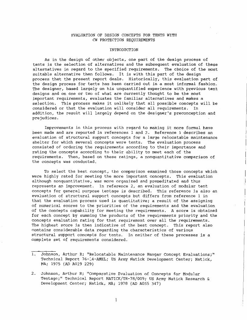
INTRODUCTION
As in the design of other objects, one part of the design process of tents is the selection of alternatives and the subsequent evaluation of these alternatives in regard to the specified requirements. The choice of the most suitable alternative then follows. It is with this part of the design process that the present report deals. Historically, this evaluation part of the design process for tents has been carried out in a most informal fashion. The designer, based largely on his unquantified experience with previous tent designs and on one or two of what are currently thought to be the most important requirements, evaluates the familiar alternatives and makes a selection. This process makes it unlikely that all possible concepts will be considered or that the evaluation will consider all requirements. In addition, the result will largely depend on the designer's preconception and prejudices.
Improvements in this process with regard to making it more formal have been made and are reported in references 1 and 2. Reference 1 describes an evaluation of structural support concepts for a large relocatable maintenance shelter for which several concepts were tents. The evaluation process consisted of ordering the requirements according to their importance and rating the concepts according to their ability to meet each of the requirements. Then, based on these ratings, a nonquantitative comparison of the concepts was conducted.
To select the best concept, the comparison examined those concepts which were highly rated for meeting the more important concepts. This evaluation although nonquantitative, was more organized and premeditated and thus represents an improvement. In reference 2, an evaluation of modular tent concepts for general purpose tentage is described. This reference is also an evaluation of structural support concepts but differs from reference 1 in that the evaluation process used is quantitative; a result of the assigning of numerical scores to the priorities of the requirements and the evaluation of the concepts capability for meeting the requirements. A score is obtained for each concept by summing the products of the requirements priority and the concepts evaluation rating for that requirement over all the requirements. The highest score is then indicative of the best concept. This report also contains considerable data regarding the characteristics of various structural support concepts for tents. In neither of these processes is a complete set of requirements considered.
1. Johnson, Arthur R; "Relocatable Maintenance Hangar Concept Evaluations;" Technical Report 76-14-AMEL; US Army Natick Development Center; Natick, MA; 1975 (AD A019 229)
2. Johnson, Arthur R; "Comparative Evaluation of Concepts for Modular Tentage;" Technical Report NATICK/TR-78/009; US Army Natick Research & Development Center; Natick, MA; 1978 (AD A055 347)

In the present report we make further improvement in the evaluation process. We conduct the evaluation against a complete set of requirements using a quantitative process and some consideration is given to the evolution of the importance of these requirements. The selection of alternative design concepts is made as a step in the design process and can be considered both as complete tent or as component concepts, such as structural support and barrier material concepts. The process also makes the consideration of several design concepts in the evaluation process quite natural.
Here we present a description of the design procedure, the evaluation process, and give some results on the evaluation of concepts for three tent components. Some needs for additional R & D to generate information to make the evaluation more precise are also discussed.
DESIGN PROCESS
The design process includes a great variety of activities from establishing requirements of specifications to the geometric design and material selection for individual components. Here our interest is in the initial and very general part of this process, the selection of and evaluation of alternative design concepts to meet a set of design requirements. This part of the design process is shown schematically in Figure 1. This process consists of establishing design requirements or objectives and a set of alternative design concepts. These are then used in an evaluation procedure to select the most suitable concept. The
FUNCTIONS TO BE SHELTERED
OPERATIONAL FACTORS
DESIGN OBJECTIVES
EVALUATION
DESIGN CONCEPTS
Figure 1. Schematic of the tentage design process
2

requirements or design objectives, part of the process is controlled by the functions to be sheltered, and certain operational factors. In this work we have used a relatively generalized set of army functions so that the number of functions considered was small. The actual functions used are listed in Table 1.
Table 1. Functions Used in the Evaluation of Concepts.
~gistics Management C I Personnel Shelter Feeding Maintenance Medical Battalion Aid Station Division Clearing Station
It will be noted that the first six of these functions are quite general while the last two are specific. These two were included because we have an ongoing program to develop shelters for these functions and the results presented here could have a direct impact on that work. In order for the Army to carry out each of its functions on the battlefield, certain operational factors must be provided for. The factors that we used are listed in Table 2.
Table 2. Operational Factors Used in the Evaluation of Concepts
Operation on a Chemical Battlefield Mobility Operation in Extreme Environments Deception Logistics Burden Safety Task Performance Degradation Space to Perform Function
Although these factors are mostly self-explanatory, expanded definitions are given in Appendix A. While this is not a complete set of operational factors, with Operation on a Nuclear Battlefield, for example, omitted, it does include those applicable to the tentage design problem. The reason for including these operational factors in the process is that their importance varies with the functions. So, in the evaluation of a concept for a given function, this relative importance of the operational factors must be included.
Each of these operational factors implies a set of tent design objectives. For example, mobility requires lightweight, low bulk and rapid erection and striking times. And of particular interest here, operation on a chemical battlefield implies a level of protection, decontamination and
3

entry/exit time. The are given in Table 3.
requirements implied by each of the operational factors One of the needs with regard to the specification of
Table 3. Requirements Implied by the Operational Factors
OPERATIONAL FACTORS
OPERATION ON CW BATTLEFIELD
MOBILITY
OPERATION IN EXTREME ENVIRONMENTS
DECEPTION
SAFETY
TASK PERFORMANCE DEGRADATION
ADEQUATE SPACE
LOGISTICS BURDEN
REQUIREMENTS
LEVEL OF PROTECTION DECONTAMINATION ENTRY/EXIT TIME
ERECTION/STRIKING TIME WEIGHT & BULK TRANSPORTABILITY
SNOW LOAD WINO LOAD MOISTURE PERMEABiliTY OPERATIONAL TEMPERATURE LIMITS SOLAR RADIATION EXPOSURE ICE SAND & OUST
BLACKOUT CAMOUFLAGE NOISE SUPPRESSION & CONTROL ELECTRONIC SHIELDING INFRARED DETECTION
FIRE RESISTANCE EXPOSED MOVING PARTS EMERGENCY EXITS ELECTRICAL GROUNDING
LIGHTING INTERNAL ENVIRONMENTAL CONTROL
USEABLE FLOOR AREA MINIMUM HEIGHT
LIFE, SERVICE/SHELF PARTS SUPPLY & WEAR EASE OF REPAIR INTERCHANGEABLE PARTS
requirements is to make that for the level of protection more definitive and complete. For example, the current requirement for the Tent, Expandable, Modular, Personnel (TEMPER) reads: "Fabrics and other material of the tentage system must be chemical agent resistant and capable of being decontaminated after chemical agent attack. All metallic parts must be painted with chemical agent resistant paint." This type of requirement is far too vague. What is needed is a specification of the external threat, including time history of concentration and type of agent, the allowable internal concentration, and the time that protection is required. This type of specification would allow determination of tent design requirements, such as air infiltration rates and liquid agent penetration rates, for fabric barrier materials.
While the operational factors imply the design objectives, the functions play a large role in setting the magnitudes of these requirements. For example, the medical function requires a much higher level of protection from chemical agents than logistics management. However, if the desire is for
4

general purpose tentage, some trade-off will be necessary among the various requirements for different functions. These trade-offs involve such conflicts as the need for high level of chemical protection, which generally increases weight and erection and striking time, and the need for high mobility, which demands low weight and rapid erection and striking time. The fact that the function has an influence through both the importance of the operational factors and in determining the magnitudes of the requirements is shown schematically in Figure 1, with the function box connected to both the operational factors and design objectives boxes.
The other side of the design process concerns the alternative design concepts for meeting the design objectives. The development of new alternative concepts is a fairly unusual event. Often what are thought to be new concepts are variations of already existing ones. For example, in a recent study described in reference 3, a concept called the skyhook was suggested for the battalion aid station. The concept consists of an arm attached to a HMMWV vehicle with the tent hung from its center via the arm. The perimeter of the tent is supported by poles. This suspension might be thought of as a new concept but, on critical examination, the arm can be thought of as either replacing the central pole in a pole-supported concept or as being an external frame, both of which are concepts in current use. Thus it is difficult to develop new concepts in a premeditated process although frequently variation in existing concepts to meet a specific situation can result from such a process. Alternative design concepts can be considered in two different ways. In the first, consideration is given to the components of a tent such as structural support, barrier material, and chemical protection components. Alternative design concepts for each of the components can be considered and evaluated. In the second way, consideration is given to complete tent design including all of its components. The evaluation process used here can be applied to both ways although here we report results only for the treatment of components.
COnnecting these two sides of the design process, requirements and design concepts, is an evaluation process which seeks to select the most suitable concept or the concept that most completely meets the requirements. The process used in this work, while based on engineering judgements and opinions, provides a means to convert the judgements into quantitative measures of the ability of the concepts to meet the requirements.
3. Anon.; Battalion Aid Station Design Concepts; Contract No. DAAK-60-82-C-0054, Task No. 14, US Army Natick RD&E Center, Attn: STRNC-UE, Natick, MA; 1984
5

EVALUATION PROCEDURE
The procedure used for the evaluation of alternative concepts is the analytic hierarchy process, which is described in detail in references 4 and 5. This procedure was chosen because it provides a means for making engineering judgements in an organized and quantitative manner, even in situations that are complicated by many interrelated considerations. This process is accomplished in two ways. First, the consideration is broken into a hierarchy and each level of this hierarchy is considered separately in the evaluation. And second, the judgements about the importance or merit of items in a given level of the hierarchy are made using pair-wise comparisons. Thus the evaluation is reduced to deciding which of two items has the most merit for all possible pairs of items under consideration. While this simplifies the evaluation process, it also increases the number of judgements that must be made. The other attractive aspect of this procedure is that it gives quantative measures of merit. The pair-wise comparisons are made by assigning numerical values in judgement of merit and the process consists of a mathematical procedure to convert these pair-wise ratings into numerical evaluations of merit of the items. The nature of the pair-wise rating process makes it possible for an individual to make inconsistent judgements, but this mathematical procedure checks the consistency of the rating while computing the evaluations of merit.
Example Using Scaled-Down Hierarchy
To describe the procedure in more detail, we use as an example a scaleddown version of the evaluation carried out in this study. To do this, we begin with the hierarchy shown in Figure 2. We have a four-level hierarchy with the goal of determining the most suitable
3structural support concept for
a tent for the medical functions and for the C I function. It should be clear that tw~ results are to be obtained, one for the medical function and one for the C I function. Level two of the hierarchy contains the operational factors; level three the requirements; and level four the component concept alternatives. Since all items on each of the levels are not related to all the items on the next, this example is classified as an imperfect hierarchy. This will require some special treatment because we want to use the same hierarchy in levels 1, 2, and 3 when we change level 4 from structural support concepts to barrier material concepts, for example. The way in which this is treated will be discussed later.
4. Saaty, Thomas L.; "The Analytic Hierarchy Process;" McGraw-Hill International Book Company; 1980
5. Saaty, Thomas L.; "Decision Making For Leaders;" Lifetime Learning Publications; Belmont, CA; 1982
6

LEVEL 1 FUNCTIONS
OPERATION ON CW BATTLEFIELD
MOBILITY
L LEVEL OF PROTECTION •
'""'DECONTAMINATION 8
ENTRY/EXIT TIME @I
ERECTION AND / STRIKING TIME
~ WEIGHT & BULK
TRANSPORT ABILITY
SNOW LOAD
WINO LOAD
C1f (-
t 1:.
OPERATION IN EXTREME MOISTURE • ENVIRONMENTS PERMEABILITY
LEVEL 2 OPERATIONAL FACTORS
OPERATIONAL TEMP. LIMITS
LEVEL 3 REQUIREMENTS
Legend
~
8 POLE
8 FRAME
8 PRESSURIZED RIB (PR)
8 AIR SUPPORTED
LEVEL 4 CONCEPT COMPONENT ALTERNATIVES
0 no influence level to level
~ influence as indicated
Figure 2. Scaled down version of the hierarchy used for evaluation of tentage structural support concepts.
7
(AS)

Level 2, Operational Factors
The evaluation process begins by deciding the relative merit or importance of the operational factor for each of the functions using the pair-wise comparison process. To do this, the following matrix is filled out for the medical function; a similar set could be done for the c3I function.
MEDICAL
Oper cw Bf Mobility
Oper in Ex Env
~ Q)
~ (J
~ ~
~ 1
1/3 1/3
·-"-·-<0
~
3 3 1 3
1/3 1
This matrix is filled out by considering each of the pairs of operational factors, deciding for each pair which is the most important or has the most merit, and assigning a degree to its importance using the numerical scale given in reference 4 and repeated here as Table 4. In light of Table 4, the above matrix for the medical function has the following meaning.
a(1,1) -Operation on CW battlefield has equal importance with itself
a(1,2) - Operation on CW battlefield is weakly more important than mobility
a(1,3) - Operation on CW battlefield is weakly more important than operation in extreme environment
a(2,3) - Mobility is weakly more important than operation in extreme environment.
Where the matrix elements are denoted as a(i,j), with i specifying the row and j the column location of the element.
The remaining elements in the matrix have meanings associated with self-comparison and the reciprocal relationships given in Table 4. Note the reciprocal character of this matrix in which the elements a(i,j) are related by the following rule: a(i,j) = 1/a(j,i). This matrix is then converted to a set of measures of importance by finding its largest eigenvalue and the associated eigenvector.
This eigenvector is the set of measures of importance. Both an intuitive justification and a mathematical proof of this procedure are given in reference 4. For the matrix given above, we get the following for A2 its largest eigenvalue and a 2 , its associated eigenvector.
8
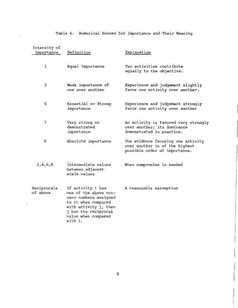
Table 4. Numerical Scores for Importance and Their Meaning
Intensity of Importance
1
3
5
7
9
2,4,6,8
Reciprocals of above
Definition
Equal Importance
Weak importance of one over another
Essential or Strong Importance
Very strong or demonstrated importance
Absolute importance
Intermediate values between adjacent scale values
If activity i has one of the above nonzero numbers assigned to it when compared with activity j, then j has the reciprocal value when compared with i.
9
Explanation
Two activities contribute equally to the objective.
Experience and judgement slightly favor one activity over another.
Experience and judgement strongly favor one activity over another
An activity is favored very strongly over another; its dominance demonstrated in practice.
The evidence favoring one activity over another is of the highest possible order of importance.
When compromise is needed
A reasonable assumption

3.1356 0.584 0.281 0.135
If we look back at the matrix and its meaning, it can be seen that these .measures of importance represent the judgement made. Operation on a CW battlefield was judged to be more important than both mobility and operation in extreme environments, while mobility is more important than operation in extreme environments. These properties are expressed in the matrix a2 which assigns an importance factor of 0.584 to operation on CW battlefield, 0.281 to mobility, and 0.135 to operation in extreme environments. These judgements have a consistency index, C of 0.067 and the criteria for acceptable consistency is that C. < o.t. This completes the analysis of level 2 and we move to level 3 fBr the analysis of the importance of the requirements.
Level 3, Requirements
The importance of the requirements must be judged for each of the operational factors so we will get three reciprocal rating matrices as follows:
Oper CW Bf
Level of Protect. Decon. E/E Time
Mobility
E/S Time Weight & Bulk Transport
10
1
1 1/3 1/5
.,_, u (J) .,_,
0 '-
Q
"'-0
(J)
> (J)
-1
1 1/7 1/7
3 1 1
I
c 0 u (J)
Cl
7 1 5
5 1 1
7 1/5
1

Oper. i.n E.E.
Snow Load Wind Load Moisture Permea. Oper. Temp. Limits
"0
"' 0 _, :;, 0 c::
V')
1 1
1/5 1/3
"0
"' 0 _, "0 c:: ·~ ::;:
1 1
1/5 1/3
"' fi}
s... • "' "' "' ,_...,
"" "' ....,
"'E ··~ s... E ·~ "' "'·~ .JEa. g_,
5 3 5 3 l 1/5 5 1
Since the total number of requirements is 10, each of these matrices should be thought of as a matrix of order 10. For ease of presentation we have given here only the nonvanishing elements of these matrices. For operation on a CW battlefield, the nonvanishing elements occupy the first three rows and columns of its matrix of order 10; for mobility, the elements shown are those in rows and columns 4 through 6; and those for operation in extreme environments occupy the last 4 rows and columns. The large number of zero entries in the pair-wise comparison matrices results from the imperfection or incompleteness of the hierarchy. Wherever a requirement is not related to an operational factor, a pair-wise comparison is not made and a zero is entered in the matrix. For example, the entry/exit time requirement is not related to either mobility or operation in extreme environments so no evaluations are made of that requirement for either of these operational factors. The result of finding the eigenvalues and eigenvectors of these three matrices is:
a = 3
0. 753 0.053 0.184
"3 3.29
c3 0.147
·~
0.559 0.185 0.155
3.03
0.014
ll
·~
0.382 0.382 0.059 0.175
4.15
0.051
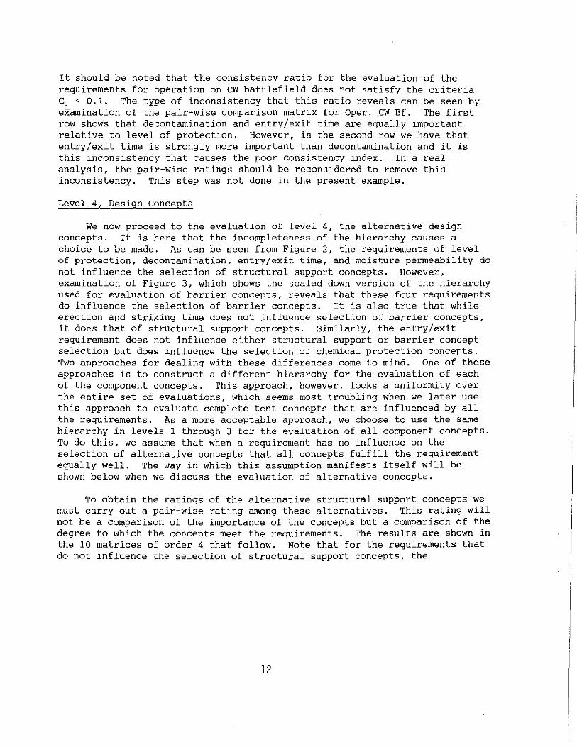
It should be noted that the consistency ratio for the evaluation of the requirements for operation on CW battlefield does not satisfy the criteria C. < 0.1. The type of inconsistency that this ratio reveals can be seen by e~amination of the pair-wise comparison matrix for Oper. CW Bf. The first row shows that decontamination and entry/exit time are equally important relative to level of protection. However, in the second row we have that entry/exit time is strongly more important than decontamination and it is this inconsistency that causes the poor consistency index. In a real analysis, the pair-wise ratings should be reconsidered to remove this inconsistency. This step was not done in the present example.
Level 4, Design Concepts
We now proceed to the evaluation of level 4, the alternative design concepts. It is here that the incompleteness of the hierarchy causes a choice to be made. As can be seen from Figure 2, the requirements of level of protection, decontamination, entry/exit time, and moisture permeability do not influence the selection of structural support concepts. However, examination of Figure 3, which shows the scaled down version of the hierarchy used for evaluation of barrier concepts, reveals that these four requirements do influence the selection of barrier concepts. It is also true that while erection and striking time does not influence selection of barrier concepts, it does that of structural support concepts. Similarly, the entry/exit requirement does not influence either structural support or barrier concept selection but does influence the selection of chemical protection concepts. Two approaches for dealing with these differences come to mind. One of these approaches is to construct a different hierarchy for the evaluation of each of the component concepts. This approach, however, locks a uniformity over the entire set of evaluations, which seems most troubling when we later use this approach to evaluate complete tent concepts that are influenced by all the requirements. As a more acceptable approach, we choose to use the same hierarchy in levels 1 through 3 for the evaluation of all component concepts. To do this, we assume that when a requirement has no influence on the selection of alternative concepts that all concepts fulfill the requirement equally well. The way in which this assumption manifests itself will be shown below when we discuss the evaluation of alternative concepts.
To obtain the ratings of the alternative structural support concepts we must carry out a pair-wise rating among these alternatives. This rating will not be a comparison of the importance of the concepts but a comparison of the degree to which the concepts meet the requirements. The results are shown in the 10 matrices of order 4 that follow. Note that for the requirements that do not influence the selection of structural support concepts, the
12

Medical Tent Example: Matrices on Extent that Concepts Meet Requirements
Level of De con. Protect. eo' ._,·
Pole 1 1 1 1 Pole 1 1 1 1 Frame 1 1 1 1 Frame 1 1 1 1 P.R. 1 1 1 1 P.R. 1 1 1 1 A, S. 1 1 1 1 A.S. 1 1 1 1
Entry/Exit "'
Erection/ Time ~ eo· Striking eo'
"" Time ~:
Pole l 1 1 1 Pole 1 1 1/9 1/9 Frame 1 1 1 1 Fran1e 1 1 1/9 1/9 P.R. 1 1 1 1 P.R. 9 9 1 1 A. S. 1 1 1 1 A.S. 9 9 1 1
Weight & Transport. Bulk c.,'
"' Pole 1 1 1/9 1/9 Pole 1 1 1/5 1/5 Frame 1 1 1/9 1/9 Frame l 1 1/5 1/5 P.R. 9 9 1 l P.R. 5 5 l 1 A. S. 9 9 1 1 A. s,. 5 5 1 1
Snow Load Wind Load eo' eo· .
"' "' Pole 1 1/3 3 7 Pole 1 1/3 1 5 Frame 3 1 3 9 Frame 3 1 3 7 P.R. 1/3 1/3 1 5 P.R. 1 1/3 1 5 A.s. 1/7 1/9 1/5 1 A. S. 1/5 1/7 1/5 1
Moisture "'
Oper. Temp. "' Permeab, "' ~ eo· Limits "' ~ Q;' eo· ~ Q; ~
"" 1<,"' ,.
"' .
"" ~<."' ,. ._,·
---Pole l 1 1 1 Pole 1 1/4 l/3 1 Frame 1 1 1 1 Frame 4 1 1 3 P.R. 1 1 1 1 p. R, 3 1 1 3 A.S. 1 1 1 1 A. S. 1 1/3 1/3 1
13

LEVEL OF PROTECTION ,. OPERATION ON ~DECONTAMINATION ,. CW BATTLEFIELD
@I PERMEABLE FABRICS MEDICAL ENTRY/EXIT TIME •
ERECTION/STRIKING TIME • MOBILITY ~ WEIGHT & BULK II(-~ l!IIMPERMEABLE TRANSPORTABILITY
COATED FABRICS C31 SNOW LOAD ~
~ """'"'" t OPERATION IN
It @I LAMINA TED EXTREME ENVIRONMENTS MOISTURE PERMEABILITY COMPOSITES
OPERATIONAL TEMP. 1-LIMITS
LEVEL 1 LEVEL 2 LEVEL 3 LEVEL 4 FUNCTIONS OPERATIONAL REQUIREMENTS CONCEPT FACTORS COMPONENT ALTERNATIVES
Legend
no influence level to level
Figure l.
influence as indicated
Scaled down version of the hierarchy us~for evaluation of barrier concepts.
14
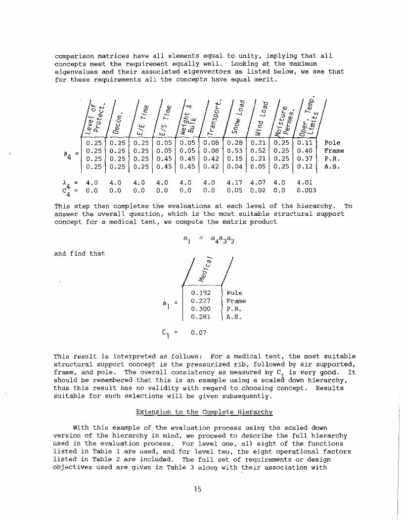
comparison matrices have all elements equal to unity, implying that all concepts meet the requirement equally well. Looking at the maximum eigenvalues and their associated eigenvectors as listed below, we see that for these requirements all the concepts have equal merit.
.,_, " " 4- • <lJ <lJ "" 5.._ '0 '0 <lJ 0.,_,
(J 12 12 0 0 0 5.._ •
-"' ·~ ·~ .,_,
Q -1 -1 "' '0 "'.,_, ,_ ,_ -<::_, "' ;)>
.,_,<ll
"' 0 o,_ c: 0 " "'E <lJ 5.._ "Q;:::J '0 c: c: ·~ <lJ
,!: ·~ -JQ "'"" (/)
"' :£c. 0.25 0.25 0.25 0.05 0.05 0.08 0.28 0.21 0.25 0.11 Pole
a4 ; 0.25 0.25 0.25 0.05 0.05 0.08 0.53 0.52 0.25 0.40 Frame 0.25 0.25 0.25 0.45 0.45 0.42 0.15 0.21 0.25 0.37 P.R. 0.25 0.25 0.25 0.45 0.45 0.42 0.04 0.05 0.25 0.12 A.S.
/-4 ; 4.0 4.0 4.0 4.0 4.0 4.0 4.17 4.07 4.0 4.01
c4 ; 0.0 0.0 0.0 0.0 0.0 0.0 0.05 0.02 0.0 0.003
This step then completes the evaluations at each level of the hierarchy. answer the overall question, which is the most suitable structural support concept for a medical tent,
and find that
we compute the matrix product
c ; l
~
"' (J ·~ 'b
~
0.192 0.227 0. 300 0.281
0.07
Pole Frame P.R. A.S.
To
This result is interpreted as follows: For a medical tent, the most suitable structural support concept is the pressurized rib, followed by air supported, frame, and pole. The overall consistency as measured by C is very good. It should be remembered that this is an example using a scalea down hierarchy, thus this result has no validity with regard to choosing concept. Results suitable for such selections will be given subsequently.
Extension to the Complete Hierarchy
With this example of the evaluation process using the scaled down version of the hierarchy in mind, we proceed to describe the full hierarchy used in the evaluation process. For level one, all eight of the functions listed in Table 1 are used, and for level two, the eight operational factors listed in Table 2 are included. The full set of requirements or design objectives used are given in Table 3 along with their association with
15

specific operational factors. With this information, the first three levels of the hierarchy can be constructed and the fourth level depends on the concepts being evaluated. The requirements that affect the selection of each of the components are shown in Table 5. It will be noted in Table 5 that two of the requirements, "exposed moving parts" and "lighting," do not influence the selection of any of the three components considered here. These have been included because they are legitimate requirements and will influence the selection of accessories and complete tent systems. Thus, to assure constancy for Levels l, 2, and 3 of the hierarchy over the evaluation of all concept components and complete tent systems, these two requirements were included here.
There are some inconsistencies in the relations between requirements and components shown in Table 5 and those shown in Figure 2 for the scaled down version of the hierarchy used in the example. The relationships shown in Table 5 are the ones to be used. The scaled down version of the hierarchy was developed early in this work before all of these relationships had become firm and, since it was to be used here only as an example, it was not updated. A more detailed statement of the requirements which were used in the evaluation tailored toward the battalion aid station are given in Appendix B.
Level four of the hierarchy contains the alternative concepts and these are listed for each component in Table 6. The alternative concepts for structural support are all well known, although the terminology "pressurized rib" may not be. This refers to the concept which has a frame made up of pressure stabilized beams and arches as illustrated in Figure 4. This concept has been investigated and the results presented in reference 6. The concept is presently being used in the Transportable Helicopter Enclosure. Likewise for the barrier materials, the permeable and impermeable coated fabrics are well-known concepts while the fabric/film laminate is not. As shown in Figure 5, the laminate is made up of a thin polymer film laminated between two fabric layers. As indicated in the figure, the film provides resistance to penetration by chemical agents and blackout while the fabric layers provide mechanical strength and protection for the film to abrasion during use. Further details on this concept are given in Reference 7.
6. Steeves, Earl C.; "Fabrication and Testing of Pressurized Rib Tents;" Technical Report NATICK/TR-79/008; US Army Natick Research and Development Command; Natick, MA; 1979 (AD A069 664)
7. Galezewski, Alexander; "Tentage Fabric Laminate Resistant to Chemical Warfare Agents;" Technical Report NATICK/TR-85/05BL; US Army Natick Research and Development Center; Natick, MA; 1985 (AD B095 949L)
16

Table 5. Concept Components and Their Related Requirements
~ ..!( o"' § "t;:j
"'"' ~.,!? Requirements §o~ CJ'e,
b~ Z:t' §1..3' '"'"' q,O
">c.,~ """'~ (JJO.,'-'
Level of Protection X X Decontamination X X X Entry/Exit Time X Erection/Striking Time X X Weight & Bulk X X X Transportability X X X Snow Load X X Wind Load X X Moisture Permeability X Operation Temp. Limits X. Solar Exposure X Ice X X Sand and Dust X Blackout X Camouflage X Noise Control X Electronic Shielding X Infrared Detection X Fire Resistance X Exposed Moving Parts Emergency Exits X Electrical Grounding X Lighting Internal Environmental Control X X Usable Floor Area X Minimum Height X Life Shelf/Service X X Parts Supply & Wear X X Ease of Repair X X Interchangeable Parts X
17

'I
' ''
ARCH ELEMENTS
FABRIC BARRIER
Figure 4. Illustration of the pressurized rib structural support concept.
EXAMPLE PROVIDES
UTER FABRIC POLYESTER WEATHERING PROTECTION LAYER DYEABILITY
BARRIER FILM PROTECTION
BARRIER FILM TEDLAR BARRIER TO CHEM. AGENTS OR MYLAR BLACKOUT PROTECTION
LOW FLAMMABILITY
NER FABRIC KEVLAR OR MECHANICAL STRENGTH LAYER POLYESTER LOW FLAMMABILITY
BARRIER FILM PROTECTION
Figure 5. Fabric/film laminate concept for barrier material.
18
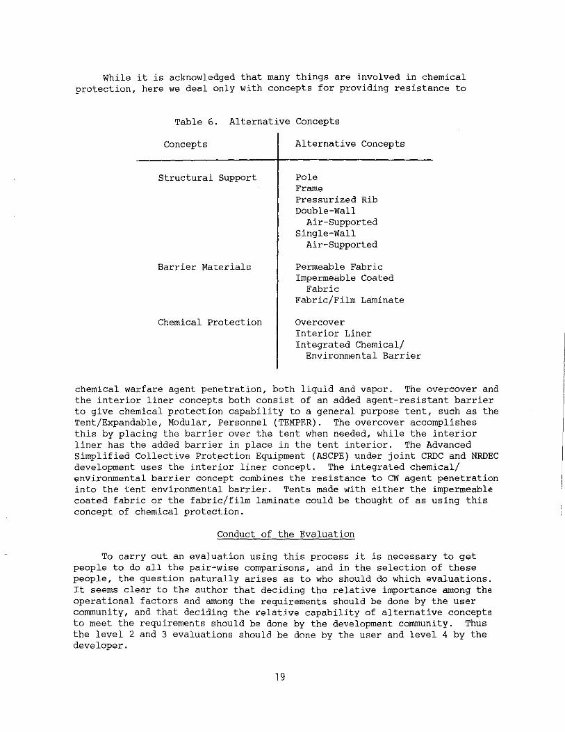
While it is acknowledged that many things are involved in chemical protection, here we deal only with concepts for providing resistance to
Table 6. Alternative Concepts
Concepts Alternative Concepts
Structural Support
Barrier Materials
Chemical Protection
Pole Frame Pressurized Rib Double-Wall
Air-Supported Single-Wall
Air-Supported
Permeable Fabric Impermeable Coated
Fabric Fabric/Film Laminate
Overcover Interior Liner Integrated Chemical/
Environmental Barrier
chemical warfare agent penetration, both liquid and vapor. The overcover and the interior liner concepts both consist of an added agent-resistant barrier to give chemical protection capability to a general purpose tent, such as the Tent/Expandable, Modular, Personnel (TEMPER). The overcover accomplishes this by placing the barrier over the tent when needed, while the interior liner has the added barrier in place in the tent interior. The Advanced Simplified Collective Protection Equipment (ASCPE) under joint CRDC and NRDEC development uses the interior liner concept. The integrated chemical/ environmental barrier concept combines the resistance to CW agent penetration into the tent environmental barrier. Tents made with either the impermeable coated fabric or the fabric/film laminate could be thought of as using this concept of chemical protection.
Conduct of the Evaluation
To carry out an evaluation using this process it is necessary to get people to do all the pair-wise comparisons, and in the selection of these people, the question naturally arises as to who should do which evaluations. It seems clear to the author that deciding the relative importance among the operational factors and among the requirements should be done by the user community, and that deciding the relative capability of alternative concepts to meet the requirements should be done by the development community. Thus the level 2 and 3 evaluations should be done by the user and level 4 by the developer.
19
The author attempted to get participation from the user community on an informal basis by working through the Joint Working Group for the development of the Battalion Aid Station. This attempt was relatively unsuccessful in that we received only four responses to the level 2 questionnaire and none from the level 3 questionnaire. Some results are included from the user level 1 responses to show the differences relative to the developer responses.
The author did complete the entire evaluation, level 2, 3, and 4, including an iteration to assure that the results were consistent. Thus, a complete evaluation exists with reasonable consistency, although it reflects only the views of a member of the development community. In addition, a team of seven evaluators, all from AMED, NRDEC, was assembled to carry out the evaluations of the level 4 alternative concepts. The evaluations of alternative concepts were carried out by giving the team instructions in the pair-wise rating process, reviewing the requirements and describing the alternative concepts after which the evaluators carried out independent judgements in filling out the evaluation form. No attempt was made to get the team to discuss each evaluation and reach a consensus. A measure of the central tendency of the group was obtained by averaging their pair-wise comparison rating. These results are presented as the team average. The measure of central tendency used here is the geometric mean. This measure is required to retain the reciprocal character of the rating matrices.
RESULTS
In this section are the results of the evaluations carried out for each of the three components discussed above. Results are first given for each of the levels of the hierarchy to convey some of the details of the evaluation. This is followed by the results of the full evaluation of the alternative concepts for structural support, barrier materials, and chemical protection.
Results From the Individual Levels of the Hierarchy
In level 2 of the hierarchy the relative importance of the eight operational factors is determined for each of the eight functions being considered. Results from this part of the survey are presented in Table 7 for both evaluator #1, from the developer community, and a representative of the medical branch of the user community. For each function in Table 7 is listed a column of scores specifying the importance of the operational factors for that function. The higher the score, the more important the factor and each column of scores sums to unity. Examination of these results reveals that the user in general rated operation in an extreme environment less important and deception and logistics burden more important than the developer. It is not possible to generalize these results to users and developers in general, but they do give a hint as to the outlook of the two communities. Much more data are needed before general statements about importance can be made.
20

Another interesting observation is seen by looking at the rating given by both the developer and user for the general medical function and the more specific battalion aid station. While there are differences in ratings for all the operational factors, the most striking difference is in the importance of mobility. It is thought to be not very important for the general medical function but among the most important for the battalion aid
Table 7. Ratings of the Importance of Operational Factors for All Functions
Developer Rating <:: 0 ·~ .,_, '0 <lJ <:: _,_,
(J 0 .,_,
"' <:: <:: c:J; (/) (jJ I ~L "' <::o, U;;,
"" <:: 0 :::;Q.J "'"' <:: <lJ '0
.,_ .:J .:2.~ "' tn
<::.,_, ·~
.,_, (J ';V> .~1.. ·~ "' o_
" <:: ·~ c:.,<:: "?,_, "'"' <lJ ·~ " "-'1:0 ~ "' 0~ '-.c: (jJ ~ ~ .,_, ·~ ·~ <lJ
'-' ,J!V> /3«: c;,--./ "- '-' Oper. on CW Batf. .138 .152 .290 .178 .178 .252 .179 .192 Mobility .026 .295 .122 .178 .243 .068 .207 .160 Oper. in Extr. Envir. .128 .141 .202 .267 .202 .167 .061 .088 Deception .043 .211 .037 .045 .073 .022 .044 .046 Logistics Burden .225 .030 .038 .035 .033 .049 .174 .181 Safety .072 .034 .160 .145 .097 .165 .053 .054 Task Perf. Degrad. .043 .070 .046 .070 .070 .199 .179 .157 Space .146 .066 .104 .081 .104 .078 .097 .121
<:: 0
·~ User Rating .,..,
"' <lJ <:: .,_, (J 0 (/) - <::
(JJ'- "' "'"' <:]) <::
<:: ·~ o"'-' <:: tn
·~ "' .:2·~ -<::.,_, <:: (jJ
"' _...,
o_ ·~ .,.., (J .,V>
"' i.. /:!<U
., <:: ·~ .::;-, ·~ "' <lJ ·~ ., ,.. <lJ <lJ-l::
~ ~ ~ ~::; ·~-u Q_(/) c;,'-'
Oper. on CW Batf. .289 .119 .225 .132 . 245 .207 .230 .202 Mobility .194 .126 .143 .178 .206 .032 .206 .188 Oper. in Extr. Envir. .061 .032 .093 .054 .198 .182 .063 .104 Deception .146 .301 .218 .265 .127 .018 .162 .172 Logistics Burden .181 .205 .091 .223 .116 .235 .222 .202 Safety .027 .028 .054 .086 .025 .149 .044 .059 Task Perf. Degrad. .062 .125 .076 .032 .041 .072 .036 .041 Space .038 .063 .099 .029 .041 .105 .036 .030
station. This difference reveals one of the dangers of using very general functions in conducting such surveys as these. It may be wise to pay some attention to the results obtained here for the general function. But before concepts are frozen for a specific application, conduct the survey again with that specific function in mind. What effect these differences have on the selection of alternative concepts will be discussed later.
21
The ratings of the relative importance of the 31 requirements are given in Table 8. It should be remembered that these ratings are the result of an evaluation done by the author, evaluator #1, a member of the development community. The partitioned character of the matrix in Table 8 is the result of the incompleteness of the hierarchy. That is, all of the requirements are not related to all of the operational factors.
Evaluation of Component Concepts Using the Complete Hierarchy
The results of the evaluation of alternative concepts for the tentage components consist of ratings of merit for each of the alternatives. These sets of ratings of merit are given for each of the eight functions. Thus they provide a basis for deciding which component concept is the most suitable for a tent to shelter a given function. These ratings of merit, which are weighted sums of the evluations over the entire hierarchy, use the evaluations of evaluator #1, the author, for levels 2 and 3, and the evaluations of a technical area expert for each component for level 4. To give some indication of the variability among the evaluators we also present the ratings of merit for the battalion aid station based on the evaluations of level 4 by each of the evaluators along with the average over all the evaluators.
Structural Support Concept
The ratings of merit for structural support concepts are presented in Tables 9 and 10. The ratings of the structural support expert in Table 9 show a clear preference for the pressurized rib concept for all functions. For the three medical functions, however, the frame support is a somewhat stronger second place choice. This is especially true for the general medical function where the frame has a nearly equal rating of merit. Examining the results in Table 10, we see that the selection of a structural support concept for the battalion aid station is not unanimous. There are first place ratings for Single-Wall Air-Support and frame in addition to those for pressurized rib. There are, however, more first place choices for pressurized rib and these choices are by larger margins than those for the other concepts. Thus the team average has the highest rating for the pressurized rib although by a very small margin. These results recommend that for the battalion aid station both the pressurized rib and frame concepts be started in the early stages of development and that the final selection between those two be based on results generated during the development.
22
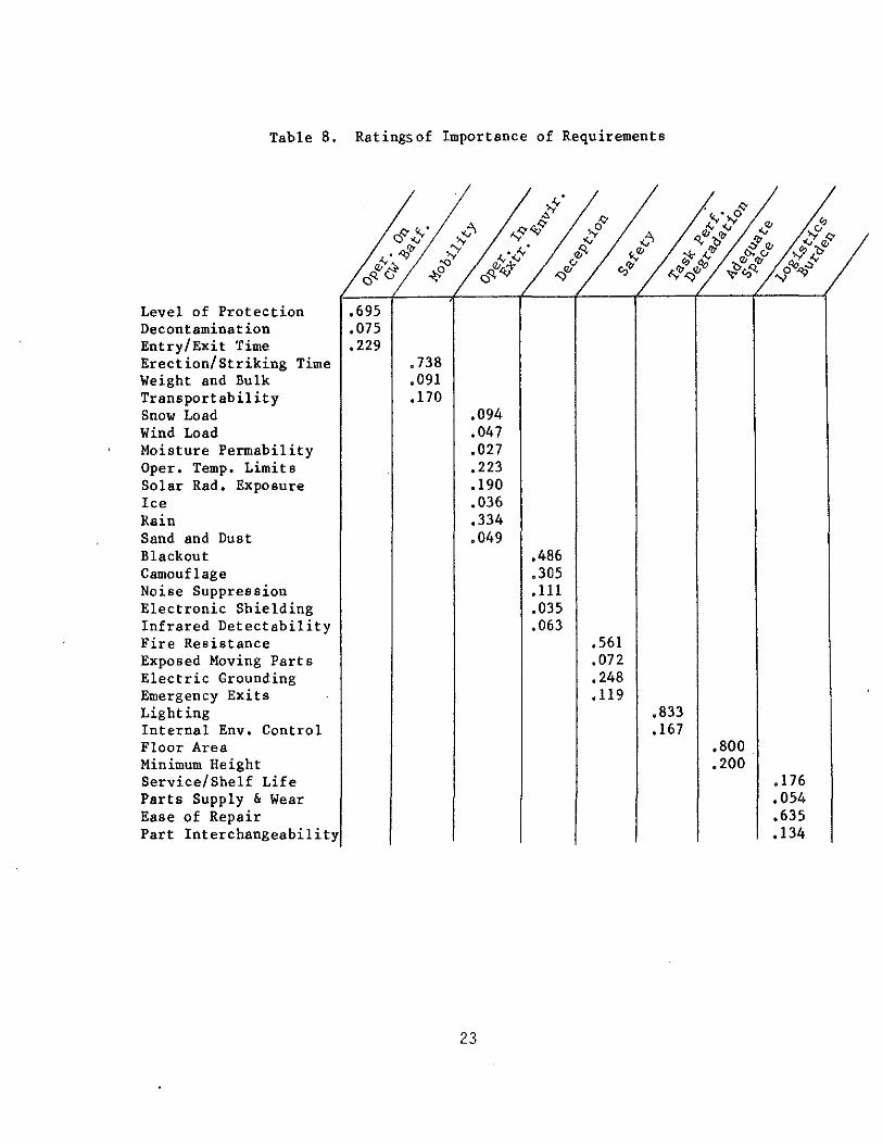
Table 8, Ratingsof Importance of Requirements
Level of Protection Decontamination Entry/Exit Time Erection/Striking Time Weight and Bulk Transportability Snow Load Wind Load Moisture Permability Oper. Temp. Limits Solar Rad, Exposure Ice Rain Sand and Dust Blackout Camouflage Noise Suppression Electronic Shielding Infrared Detectability Fire Resistance Exposed Moving Parts Electric Grounding Emergency Exits Lighting Internal Env. Control Floor Area Minimum Height Service/Shelf Life Parts Supply & Wear Ease of Repair Part Interchangeability
,695 .075 ,229
• 738 ,091 .170
,094 .047 .027 .223 .190 .036 .334 .049
23
.486
.305
.111
.035
.063 .561 ,072 .248 ,119
.833
.167 ,800 .200
.176
.054 ,635 ,134

Table 9.
Function ....,
Vl c UQJ
Structural ·~ E +'<U
Support V> en ·~ "'
Concept enc 0<0 ...J,;:
Pole .174
Frame .172
Pressurized .280 Rib
Double-Wall .184 Air-Supported
Single-Wall .189 Air-Supported
Ratings of Merit for Structural Support Concepts For All runct1ons
QJ u
~ c QJ "' c s.. en c c QJ c QJ 0+' ·~ +' Vl ~ '0 c
~ S- QJ QJ ·~ (V') <U£ QJ "' u 0..<./) "- "" .174 .183 .179 .174
.176 .190 .187 .179
.284 .245 .258 .277
.192 .185 .187 .186
.174 .195 .190 .183
c 0 c en
~ ·~ c 0 c
"' ~ 0 •r- ·.--u "' ·~ Vl s.. . ·~
...., ·>-' ·~ "' '0 +''0<0 > QJ QJ r'd •r- +' ·~~
"' c:J<l:<./l C> u
.169 .161 .165
.224 .202 .201
.236 .277 .268
.187 .189 .186
.184 .171 .179
Level 2 Evaluator #1 Level 3 Evaluator #1 Level 4 Evaluator #1
Table 10. Ratings of Merit for Structural Support Concepts For All Level 4 Evaluators
L eve 4 Evaluator
Structural Support ~
Concept "" Pole .161
Frame .202
Pressurized .277 Rib
Double-Wall .189 Air-Supported
Single-Wall .171 Air-Supported
(Battalion Aid Station)
N (V') "" L(')
"" "" "" "" .179 .193 .195 .153
.223 .206 .224 .229
.228 .182 .188 .264
.182 .181 .191 .165
.188 .238 .202 .188
24
.. <D ,..... co "" "" ""
.189 .197 .180
.184 .244 .215
.218 .146 .217
.191 .171 .185
.218 .241 .202
Level 2 Evaluator #1 Level 3 Evaluator #1
* Team Average

Barrier Material Concepts
The ratings of merit for barrier material concepts are presented in Tables ll and 12. The ratings of merit with the expert level 4 evaluation clearly and decisively recommend the laminated fabric for all functions. Similarly, for all level 4 evaluators the laminated fabric concept received the highest ratings of merit for use as a barrier material in the battalion aid station. Of all the evaluations done, this is the most unanimous and decisive and does not leave any question as to which concept should enter into development.
Table 11. Ratings of Merit for Barrier Material Concepts For All Functions
Function +' VlC: ~
UQJ QJ ·~ E c: <-
Barrier ;..>QJ c: QJ VlO> 0;..>
Material ·~ "' Vl ~ Ole ~ <- QJ
Concepts 0"' M QJ..C: __l;E L) 0. l/)
Permeable .284 .303 .264 Fabric
Impermeable .269 .286 .292 Fabric
Laminated .447 .411 .444 Fabric
25
QJ u c: <0
Ol c: c: QJ ·~ +' -o c: QJ ·~ QJ "' IL "'
.292 .291
.291 .289
.417 .420
c: 0 COl
~ ·~ c: 0 c:
"' ~ 0 .,.... •r-u "' ·~ Vl <-. ·~ +' +' ·~"' -o +' -o "' >OJ QJ I'd .,.... +J ·~~
::E CO<l:U) C) L)
.271 .277 .276
.299 .278 .277
.429 .445 .446
Level 2 Evaluator #1 Level 3 Evaluator #1 Level 4 Evaluator #3

Table 12. Ratings of Merit for Barrier Material Concepts For All Level 4 Evaluators
(Battalion Aid Station)
Level 4 Evaluator
Barrier Materia 1 Concept
~ N M "'" ..,.,
""' ""' ""' ""' "" Permeable
.269 .287 .277 .311 .254 Fabric
Impermeable .332 .310 .278 .315 .271 Fabric
Laminated .399 .403 .445 .374 .475 Fabric
Chemical Protection Concepts
.. <.0 r-- ct:)
"" ""' ""' .284 .289 .283
.301 .304 .298
.415 .407 .419
Level 2 Evaluator #1 Level 3 Evaluator #1
* Team Average
The ratings of merit for chemical protection concepts are presented in Tables 13 and 14. The ratings shown in Table 13 and obtained with the level 4 evaluations of the chemical protection expert give a decisive recommendation to the integral environmental/chemical barrier concept. For the battalion aid station, this recommendation is very nearly unanimous among all the level 4 evaluators. Only evaluator #6 disagreed with this recommendation and the ratings of merit resulting from his evaluation are in sharp disagreement with those of other evaluators. Examination of the details of the evaluation of evaluator #6 does not reveal a specific area of disagreement but a general disagreement regarding the ability of the alternative concepts to meet all the requirements.
26

Table 13. Ratings of Merit for Chemical Protection Concepts For All Functions
Function .., "'.:: --" ow QJ
'rlS <: ... .j.JQJ o= QJ
Chemical "'"" 0'-' ..-lei) "''"" Protection ooa H ... QJ QCI) "' Cll.C
Concept >-'l:>:: u P;CJ"l
Over cover .315 .307 .310
Interior ,276 .256 .296 Liner
Chem/Envir. ,409 .438 .395 Barrier
QJ 0 .:: <I)
"" <: o= QJ .... .j.J
'tl o= QJ .,... QJ <I) ~ :>::
.316 .310
.281 .266
.403 .423
.:: 0 <:oo
H .... .:: 0 o= o= <I) H 0 ........ 0 0 <I) .... rn .., ""' .... .... .j.J -MCI).j.J
'tl .j.J't)CI) ~ Cll <I) QJ Cl)'rl+J 'rlH '-'
:>:: "'<oo AUUl
.316 .310 .311
.309 ,277 .289
.375 .412 .399
Level 2 Evaluator #1 Level 3 Evaluator #1 Level 4 Evaluator #7
Table 14. Ratings of Merit for Chemical Protection Concepts For All Level 4 Evaluators
(Battalion Aid Station)
Level 4 Evaluator
Chemical Protection
.--< N M "' "' Concept "" "" "" "" "" Overcover ,288 .269 .279 .251 ,247
Interior .308 .269 ,306 .311 ,323 Liner
Chem/Envir. .403 .462 .416 .438 .430 Barrier
27
.. "' r-- 00
"" ""' "" ,331 .310 ,289
,364 .277 .304
.305 .412 .407
Level 2 Evaluator #1 Level 3 Evaluator #1
* Team Average

Influence of User Evaluation of Level 2
It was possible to obtain an evaluation of the relative importance of the operational factor from a user representative in the medical community. The results of this evaluation are given in Table 7, along with similar results from a developer representative. There are what appear to be substantial differences between the user and developer results so these two sets of level 2 evaluations were used in obtaining evaluations of the component concepts over the complete hierarchy. These results, which are presented in Tables 15, 16, and 17, will indicate what effect these differences between user and developer evaluation have on the selection of alternative concepts. In these figures, we have results for the component area expert as the level 4 evaluator, evaluator #1 as the level 3 evaluator, and both a user and a developer representative as the level 2 evaluator. Examination of these results reveals that for all three components, structural support, barrier material, and chemical protection, and for all functions, the selection of the best concept among the alternatives is not changed when going over to the user evaluation.
The second, third, fourth, and fifth place choices for structural support concepts, however, do change considerably between the user and developer evaluations of level 2. There is also some variability among the functions in the second and third place choices for barrier materials between these two evaluations. But for all functions, the order of selection of the chemical protection concepts i.s the same for both the user and developer. Thus the user evaluations of level 2 do not seem to alter the selection of alternatives significantly.
Table 15. Effect of User Evaluation of Operational Factors on Selection of Alternative Structural Support Concepts
Function Logistics c 3
I Personnel Feeding Structural Management Shelter Support Concepts User Devel. User De vel. User De vel. User Devel
Pole .180 .174 .173 .174 .178 .183 .184 .179
Frame .188 .172 .202 .176 .192 .190 .182 .187
Pressurized .260 Rib .280 .251 .284 .255 .245 .255 .258
Double-Wall .194 Air-Supported .184 .193 .192 .188 .185 .196 .187
Single-Wall .177 .189 .180 Air-Supported .174 .187 .195 .182 .190
28
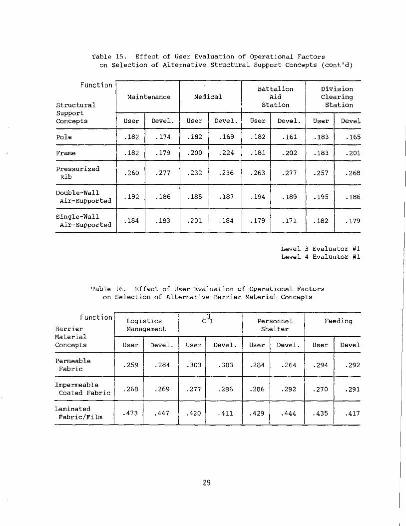
Table 15. Effect of User Evaluation of Operational Factors on Selection of Alternative Structural Support Concepts (cont'd)
Function Maintenance Medical
structural Support Concepts User Devel. User Devel.
Pole .182 .174 .182 .169
Frame .182 .179 .200 .224
Pressurized .260 .277 .232 .236 Rib
Double-Wall .192 .186 .185 .187 Air-Supported
Single-Wall .184 .183 .201 .184 Air-Supported
Battalion Division Aid Clearing
Station Station
User De vel. User Devel
.182 .161 .183 .165
.181 .202 .183 .201
.263 .277 .257 .268
.194 .189 .195 .186
.179 .171 .182 .179
Level 3 Evaluator #1 Level 4 Evaluator #1
Table 16. Effect of User Evaluation of Operational Factors on Selection of Alternative Barrier Material Concepts
Function Logistics c3r Personnel Feeding Barrier Management Shelter Material Concepts User Devel. User Devel. User De vel. User Devel
Permeable .259 .284 .303 .303 .284 .264 .294 .292 Fabric
Impermeable .268 .269 . 277 .286 .286 .292 .270 .291 Coated Fabric
Laminated .473 .447 .420 .411 .429 .444 .435 .417 Fabric/Film
29

Table 15. Effect of User Evaluation of Operational Factors on Selection of Alternative Barrier Material Concepts (cont'd)
Function Maintenance Medical
Barrier Material Concepts User Devel. User De vel.
Permeable .277 .291 .270 .271 Fabric
Impermeable .272 .289 .274 .299 Coated Fabric
Laminated .451 .420 .455 .429 Fabric/Film
Battalion Division Aid Clearing
Station Station
User De vel. User Devel
.259 .277 .278 .275
.254 .278 .258 .277
.457 .445 .454 .446
Level 3 Evaluator #1 Level 4 Evaluator #3
Table 17. Effect of User Evaluation of Operational Factors on Selection of Alternative Chemical Protection Concepts
Function Logistics CJI Personnel Feeding Chemical Management Shelter Protection Concepts User Devel. User De vel. User De vel. User De vel
Overcover .299 . 315 .318 .307 .309 .310 .317 .315
Interior .283 .275 .300 .255 .294 .295 .284 . 281
Liner
Chem/Enviro. .418 .409 .382 .438 .397 .395 .399 .403 Barrier
30
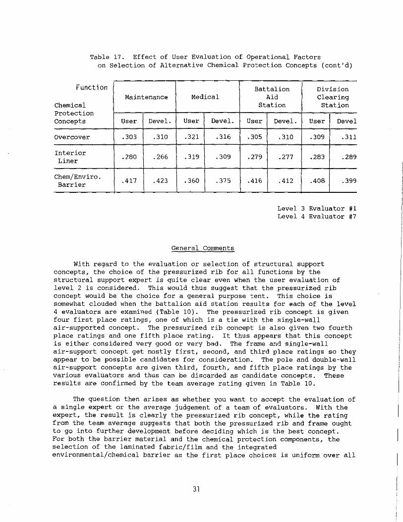
Table 17. Effect of User Evaluation of Operational Factors on Selection of Alternative Chemical Protection Concepts (cont'd)
Function Maintenance Medical
Chemical Protection Concepts User Devel. User De vel.
Overcover .303 .310 .321 .316
Interior .280 .266 .319 .309 Liner
Chem/Enviro. .417 .423 .360 .375 Barrier
General Comments
Battalion Division Aid Clearing
Station Station
User Devel. User De vel
.305 .310 .309 .311
.279 .277 .283 .289
.416 .412 .408 .399
Level 3 Evaluator #1 Level 4 Evaluator #7
With regard to the evaluation or selection of structural support concepts, the choice of the pressurized rib for all functions by the structural support expert is quite clear even when the user evaluation of level 2 is considered. This would thus suggest that the pressurized rib concept would be the choice for a general purpose tent. This choice is somewhat clouded when the battalion aid station results for each of the level 4 evaluators are examined (Table 10). The pressurized rib concept is given four first place ratings, one of which is a tie with the single-wall air-supported concept. The pressurized rib concept is also given two fourth place ratings and one fifth place rating. It thus appears that this concept is either considered very good or very bad. The frame and single-wall air-support concept get mostly first, second, and third place ratings so they appear to be possible candidates for consideration. The pole and double-wall air-support concepts are given third, fourth, and fifth place ratings by the various evaluators and thus can be discarded as candidate concepts. These results are confirmed by the team average rating given in Table 10.
The question then arises as whether you want to accept the evaluation of a single expert or the average judgement of a team of evaluators. With the expert, the result is clearly the pressurized rib concept, while the rating from the team average suggests that both the pressurized rib and frame ought to go into further development before deciding which is the best concept. For both the barrier material and the chemical protection components, the selection of the laminated fabric/film and the integrated environmental/chemical barrier as the first place choices is uniform over all
31

functions and all but one evaluator. Thus these choices are the appropriate ones also for general purpose tents. Not only is the conclusion supported by the unanimity of the ratings, but also by the fact that the first place choices for barrier materials and chemical protection received substantially higher ratings than the other concepts.
In using these results to make decisions, the question of what might be called the authority of the number used in the rating becomes a question. Using the team average for structural support concepts in Table 10 as an example, we can clearly say that the pressurized rib concept is the best concept because it got the highest score. However, the frame concept got a score very slightly smaller. So the question must be asked: Is the difference large enough to remove the frame concept from consideration? It must be remembered, while this is a quantitative evaluation process, the process is really the quantification of engineering judgements or opinions. In view of this, it does not seem reasonable to rule out the frame concept based on the small difference in rating given by the team average. If, however, we were going to base our selection on the evaluation of the expert for structural support, evaluator #1 in Table 10, the rating of the pressurized rib concept is sufficiently larger than that for all other concepts that it could be recommended to move forward in development without a backup concept. The first place choices for both barrier material and chemical protection have sufficient authority in the sense described to recommend moving forward in their development without backup.
The authority of these evaluations could be significantly increased by removing the element of judgement and opinion wherever possible. This could be done with the use of engineering analysis and experiment. For example, the evaluation of structural support concepts for ability to carry snow loads could and should be settled by design analysis. It could be determined which concept can meet the snow load requirement for the least weight for a given size structure. Similarly, the question of erection/striking time could be made more precise by either conducting experiments or going into the field to observe the erection and striking of various tents, thus developing a data base upon which the evaluation can be made. Examination of this evaluation process will suggest a series of investigations such as these that will provide a data base to increase the authority of this evaluation process.
CONCLUDING REMARKS
An evaluation of design concepts for tents with chemical warfare (CW) protection requirements has been completed for eight generalized army functions. The evaluation was carried out using the analytic hierarchy process, which gives a quantitative measure of relative merit. Alternative concepts for the structural support, barrier material, and chemical protection components were evaluated. The results recommend the following for further development: the pressurized rib concept for structural support with the frame concept as a backup; the laminated fabric/film for the barrier material; and an integral environmental/chemical barrier for chemical protection. The laminated fabric film is a barrier material that has the environmental and chemical barrier integrated or combined. In the
32

development of this one concept the requirements for two components, barrier material and chemical protection, are satisfied. These recommendations are especially applicable to the battalion aid station because a set of requirements for that item was used in the evaluation.
The process used here for the evaluation of tentage components is sufficiently general for use in evaluation of a complete tent system. This is accomplished by creating a new level four of the hierarchy consisting of some number of alternative tent designs, with each of these designs associated with all of the level three requirements.
33

REFERENCES
1. ,Johnson, Arthur R.; "Relocatable Maintenance Hanger Concept Evaluations;" Technical Report 76-14-AMEL; US Army Natick Development Center; Natick, MA; 1975 (AD A019 229)
2. Johnson, Arthur R.; "Comparative Evaluation of Concepts for Modular Tentage;" Technical Report NATICK/TR-78/009; US Army Natick Research and Development Center; Natick, MA; 1978 (AD A055 347)
3. Anon.; Battalion Aid Station Design Concepts; Contract No. DAAK-60-82-C-0054, Task No. 14, US Army Natick Research, Development and Engineering Center, Attn: STRNC-UE, Natick, MA; 1984
4. Saaty, Thomas L.; "The Analytic Hierarchy Process;" McGraw-Hill International Book Company; 1980
5. Saaty, Thomas L.; "Decision Making for Leaders; 11 Lifetime Learning Publications; Belmont, CA; 1982
6. Steeves, Earl C.; "Fabrication and Testing of Pressurized Rib Tents; 11
Technical Report NATICK/TR-79/008; US Army Natick Research and Development Command; Natick, MA; 1979 (AD A069 664)
7. Galezewski, Alexander; "Tentage Fabric Laminate Resistant to Chemical Warfare Agents;" Technical Report NATICK/TR-85/058L; US Army Natick Research and Development Center; Natick, MA; 1985 (AD B095 949L)
34

APPENDIX A
Definition of Operational Factors
35

APPENDIX A
Definition of Operational Factors
Operation on the CW Battlefield
Operation on the CW battlefield implies the capability to carry out or at least in some orderly fashion complete a function while under attack by chemical weapons. Included are situations in which a function is ongoing when attack is initiated and carrying out a function during an ongoing attack. Successful operation of a function on the CW battlefield is dependent on the level and method of protection. The highest level of protection for a shelter is collective protection but lower levels such as ventilated facepieces, suits, and filtered masks may be adquate and should be considered for some functions.
Mobility
Mobility is the capability to move about on the battlefield with ease, speed, and frequency. Factors affecting the mobility of shelters are weight, bulk, and erection/striking time.
Operation in Environmental Extremes
This operational factor deals with the capability to carry out or at least complete in an orderly manner a function in the presence of extreme environments including rain, snow, wind, humidity, solar load, etc. These climatic extremes imply requirements which in turn will affect design concepts such as barrier material, structure, and interior conditions.
Deception
Deception is simply the capability to carry out a function without being detected by the enemy. Deception techniques include camouflage, blackout protection, and noise suppression.
Adeguate Space to Perform Function
This operational factor is self-explanatory and obviously space is essential to the performance of a function. What needs to be considered here is how space demanding or sensitive a function is. If somewhat smaller than optimum space is allocated for a function, will this degrade the performance of the function? Space requirements to be considered in a shelter are height, unencumbered floor space, adequate work space, and air space needed for proper ventilation.
Safety
This operational factor encompasses all safety characteristics, for example, fire resistance.
36

Task Performance Degradation
This factor involves the sensitivity of the function to disruption or performance degradation by any events including noise, high wind, CW attack, wearing of CW protection equipment, low light levels to avoid detection, etc. The question to be asked is how important relative to the other factors is freedom from disturbance to the completion of the function.
Logistics Burden
The logistics burden is the need to carry out all the logistics operations associated with the completion of a given function such as supply, storage, and maintenance. Information is sought on how important logistics operations are to the completion of a given function.
37

APPENDIX B
Detailed Statement of Requirements
38

Appendix B
Detailed Statement of Requirements
I. Operation on CW Battlefield
a. Level of Protection
1. The internal environment must be kept below any incapacitating chemical dosages for a minimum of 8 hours.
b. Decontamination
1. Decontamination procedures must reduce the hazard sufficiently so the unit can continue to function.
2. Decontamination time must be kept to a minimum.
c. Entry/Exit Time
1. A patient flow of 40-50 per hour can be expected.
II. Mobility
a. Erection/Striking Time
1. Two men, 15 minutes (completely operational)
b. Weight & Bulk1
1. Maximum weight will not exceed 1.5 lb/ft2
2. Maximum bulk will not exceed .14 ft3jft2 of floor space.
c. Transportability
1. Must have airdrop capability and be suitable for manual loading into existing ground and air transport
III. Operation in Environmental Extremes
a. Snow Load
1. 10 lb/ft2
b. Wind Load
1. Steady: 50 mph
3Y

c. Moisture Permeability
1. Interior humidity must remain about 15%, but not exceed 80%.
d. Operational Temperature Limits
e. Solar Radiation Exposure
1. 0 to 355 W/m 2
f. Ice
1. 3/4" ice buildup
g. Rain
1. 2"/hour @ 20 mph windspeed
h. Sand & Dust
1. Blowing sand @ 40 mph for 20 hours
IV. Deception
a. Blackout
1. Blackout protection must be available without the use of a liner.
b. Camouflage
1. Should conform to current camouflage techniques, standards, and practices.
c. Noise Suppression
1. Noise levels should not exceed 65dB.
d. Electronic Shielding
1. Minimize EMI levels
e. Infrared Detectability
1. Reduce infrared susceptibility
V. Safety
1. Flame resistance (Fed. Std. 191, Test Method 590)
40

1. After flame of 5 seconds maximum
2. Char length of 4.5 inches maximum
b. Exposed Moving Parts
1. Guards shall be provided on all moving parts.
c. Electric Grounding
1. All equipment shall be designed to be at ground potential.
d. Emergency Exits
1. Simple to operate
2. Readily accessible
3. Unobstructed
4. Easy to locate and operate in the dark
5. Quick opening in 3 seconds or less
6. Requires 10-13 lb operating force to open
7. Evacuation of all personnel and patients shall be possible in 60 seconds, using only one-half of the exits.
VI. Task Performance Degradation
a. Lighting
1. General work: 540-755 Lux.
2. Precision work: 1075-1615 Lux.
b. Internal Environmental Control
1. Interior Temperature: 65°-85°F
2. Ventilation
a.
b.
6-10 ft 3/min/man
Air should be moved past an individual at a velocity not more than 100 ft/min, 65 ft/min if possible.
3. Humidity
a. Upper limit of 80% relative humidity at 88°F dry bulb.
41

4. Temperature Uniformity
a. Temperature of air at the floor level and head level should not differ by more than 10°F (5.5°C}.
VII. Adeguate Space
a. Floor area: 440 ft 2
b. Minimum height: 7 ft
VII. Logistics Burden
a. Service/Shelf Life
1. Service: 2 years
2. Shelf: 6 years
b. Parts Supply & Wear
1. Replacement of any one component will occur not more often than every 1,000 hours.
2. 72 hour separation from supply train required.
3. Total maintenance time per 24 hours will not exceed 1 hour.
4. All materials should be mildew resistant (fungus test MIL-STD-810B).
c. Ease of Repair
1. Repairable in the field
2. Repair/replacement requires time not in excess of 30 minutes.
d. Parts Interchangeability
1. Parts should be standardized to the greatest extent possible.
2. Parts should be coded for easy I.D. and interchanging.
42
DISTRIBUTION:
USAFTAWC/TALO Eglin AFB, FL 32542-6008
USAFTAWC/THLO Eglin AFB, FL 32542-6008
Commandant U.S. Army Chemical School Attn: ATZN-CM-CS (Ben Lane) Ft. McClellan, AL 36205
Commander U.S. Army Test & Evaluation Command Attn: AMSTE-TE-T/AMSTE-EV-0 Aberdeen Proving Ground, MA 21005-5055
Commandant Academy of Health Sciences Attn: HSHA-CDM/HSHA-DCD/HSHA-CDM/
HSHA-CTE Ft. Sam Houston, TX 78234
Director MTMC Attn: ATIC-DMD Newport News, VA 23606-0276
Commander Belvoir RD&E Center Attn: STRBE-FED (Robert Rhodes) Ft. Belvoir, VA 22060
U.S. Army Field Artillery Center Attn: ATSF-CD Ft. Sill, OK 73505
Commander Chemical RD&E Center Attn: SMCCR-PPC/SMCCR-PPP Aberdeen Proving Ground, MD 21021
Commandant U.S. Army Quartermaster School Attn: ATSM-CD Ft. Lee, VA 23801
Commander U.S. Army Troop Support Command Attn: AMSTR-E St Louis, MI 63120
Commandant U.S. Army Infantry School Attn: ATSI-CD Ft. Benning, GA 31905
Headquarters Wright Patterson Air Force Base Attn: ASD/AESD WPAFB, OH 45433
Commander Combined Arms Center Attn: ATZL-CAM-I Ft. Levenworth, KS 66027
Headquarters DA Attn: DASG-HCS/DASG-HCD-D Washington DC 20310
Commander u.s. Army Medical RD&E Center Attn: SGRD-E-ES/SGRD-PLE/SGRD-UMA Ft. Detrick Frederick, MD 21701
Commander u.s. Army Logistics Center Attn: ATCL-CFT Ft. Lee, VA 23801
Commander Ordnance School Attn: ATSL-CD/ATSL-CD-CS Aberdeen Proving Ground, MD 21010
Dept of Defense Research & Eng. Department of Defense Washington, DC 20315
Conunandant Transportation School Attn: ATSP-CD Ft. Eustis, VA 23604
Conunander U.S. Army Soldier Support Center Attn: ATSG-DDM/ATZI-NMM Ft. Benjamin Harrison, IN 46216
Commander Army Materiel Command Attn: DRCDE-SSN Alexandria, VA 22333
Conunander Tank and Automotive Command Attn: DRCPM-TV-S/DRCPM-TV/AMCPM-TUL Warren, MI 48090
Commanding General MCDEC Code D073 Quantico, VA 22134
Commander NSWC Code H34 Dahlgreen, VA 22448
Conunander U.S. Army CECOM Attn: AMSEL-SEI-V Ft. Monmouth, NJ 07703
Commander U.S. Army NRDEC Attn: STRNC-USOT Kansas Street Natick, MA 01760-5017
Commander Headquarter US Army Training and Doctrine Command ATTN: ATCD-NC ATTN: ATCD-S Fort Monroe, VA 23651
Commander USA Foreign Science & Tech Ctr 220 Seventh St, NE Charlottesville, VA 22901
Commander US Army Materiel Development &
Readiness Command ATTN: DRDCE-SSN 5001 Eisenhower Avenue Alexandria, VA 22333
Administrator Defense Technical Info. Ctr. ATTN: DTIC-DDAB Cameron Station BG 5 Alexandria, VA 22314
HQDA ATTN: DAMA-CSS WASH DC 20310
Commander HQ US Army Troop Support & Aviation
Materiel Readiness Command ATTN: DRSTS-WH ATTN: Technical Library 4300 Goodfellow Blvd St Louis, MO 63120
Commander US Army Transportation School ATTN: Technical Library ATTN: ATSPQ-CMT Ft. Eustis, VA 23604
Commander US Army Quartermaster School ATTN: ATSM-CD ATTN: Technical Library Fort Lee, VA 23801

Commander US Army Test and Evaluation Command ATTN: DRSTE-CT-A Aberdeen Proving Ground, MD 21005
Director US Army Materials and Mechanics
Research Center ATTN: DRXMR-SM Watertown, MA 02172
Office of The Surgeon General ATTN: DASG-HCL Washington, D.C. 20310
Commander US Army Cold Regions Research &
Engineering Laboratory ATTN: Technical Library Hanover, New Hampshire 03755
Air Force Medical Materiel Field Office ATTN: SFMMFO/FOM Fort Detrick, MD 21701
HQ AFESC/DEOP Tyndall AFB FL 32403
Commander Brooks AFB ATTN: HSD-YAMC San Antonio, TX 78235-5000
Naval Civil Engineering Laboratory Code LEA Port Hueneme, CA
Commandant USAMMCS Attn: ATSK-CMM
93043
Redstone Arsenal, AL 35898