Embed Size (px)
Citation preview
AUT Journal of Civil Engineering
AUT J. Civil Eng., 1(1) (2017) 67-76DOI: 10.22060/ceej.2017.12351.5200
Evaluation of Damage Indicators of Weld and Cyclic Response of Steel Moment Frame Connection Using Side Stiffener Plates
M. Raftari*, R. Mahjoub, A. Hekmati
Departement Of Civil Engineering, Faculty Of Engineering, Khoramabad Branch, Islamic Azad University, Khoramabad, Iran
ABSTRACT: The beam to column connection with side stiffeners in steel moment frames is a moment resisting connection. This type of connection is able to reduce the damage caused by seismic loads. It also has the capability to increase the rate of energy absorption. Moreover, the plastic joints in the base beam significantly reduce the failure of the connection components, including connection region plates, welding, column, etc. In this paper, after introducing the damage indices, the indices were extracted and compared in the weld of the components of connection under cyclic loading. Then, the hysteresis behavior of the connection was examined. For this purpose, modeling was done using finite element method by considering the effects of large deformations. The effects of changes in the thickness of top flange plate, presence or absence of the stiffener plates inside the column and the column thickness changes on the damage indices of the weld of different parts of the connection were studied. Finally, the effect of variations of aforementioned components on the hysteresis parameters of the connection was examined and compared. The results of the present study showed that the variation of the components of connection leads to dramatic changes of a number of damage indices and thereby hysteresis parameters, including the rate of energy loss. As a result, the potential for damage failure may vary.
Review History:
Received: 10 January 2017Revised: 2 March 2017Accepted: 13 March 2017Available Online: 18 March 2017
Keywords:
Energy AbsorptionDamage IndexFinite ElementLarge DeformationsWelding
67
1- IntroductionI-shaped beam connection to steel box column with lateral stiffener plates is a moment resistant connection and has received great attention for its good performance. Connection components include Top Flange Plate, Bottom Flange Plate, Horizontal Stiffener Plates, Vertical Stiffener Plates whose details are shown in Figure 1. Connection performance affecting parameters are outlined as column dimension, beam dimension, lateral stiffeners shapes and dimensions, use or non-use of column continuity plates, weld, and beam-to- column top/bottom flange plates dimensions. Any of the abovementioned elements can significantly affect the connection behavior. There are a number of studies on the behavior of connections and their improvement with the addition of T-stiffeners. White et al. [11] conducted studies on steel connection behavior to lateral and external stiffener plates. They observed that connections with triangular stiffener plates are less rigid than connections with lateral stiffeners plates. Ghobadi et al. [14] found that weld electrode toughness had the most significant effect on the overall performance of the welded joints. Shanmugan et al. [4] studied beam-to-column box on 15 different samples with different stiffener dimensions. During this study, connections were exposed to cyclic loads. Results indicated very appropriate connection seismic behavior compared to the connections with external stiffener plates. Furthermore, some of the connections were studied under finite element method
through which the results indicated a high connection moment resistance, according to connections design standards. Deylami et al. [15] indicated the existence of the vertical trapezoidal stiffeners decrease the rate of stress concentration on the groove weld into beam flange plate which reduces brittle fracture on the weld. Ghobadi et al. [6] studied steel connections performances which have lateral stiffener plates and the results indicated improved connection formation and crack growth removal at the connection source. Shin et al. [7] in their studies, compared analytical and experimental behaviors of connections with external stiffener plates. Three types of failure modes were reported during the study such ashorizontal element failure, vertical element failure, and beam failure. Chen et al. [5] performed their studies on connection samples with lateral stiffener plates. The results indicated crack growth in horizontal stiffener plate apex at beam connection point. Moreover, Daylami et al. [13] in their study reported stress concentration reduction at connection zone welds due to vertical stiffener plate presence. The result was similar to those of other researchers in the field. As far as welded connections failure and different types of damages are concerned, many studies took place after Northridge earthquake. Lemaitre [3] after conducting a study in this regard, categorized various conditions and load damages as brittle damage, ductile damage, creep damage, low range damage, and high range damage. According to the conducted studies on steel structure, brittle and ductile damage, and low range fatigue affect seismic beam-to-column performance. According to the above categorization, brittle damage occurs without substantial plastic strain. Ductile damage refers to the
Corresponding author, E-mail: [email protected]

M. Raftari et al., AUT J. Civil Eng., 1(1) (2017) 67-76, DOI: 10.22060/ceej.2017.12351.5200
68
damage that coincides with plastic deformations larger than plastic strain threshold. Finally, low range fatigue damage occurs when materials are under the influence of cyclic forces for high stress-strain values. Wang et al. [2] presented fracture prediction of welded steel connections using traditional fracture mechanics and calibrated micromechanics based models. The present study mainly aims to study steel moment frames connections damage indices under the influence of cyclic load. Furthermore, to evaluate different damage indices and compare the discrepancies among these indices was used of finite element software of ABAQUS and conduct dynamic analysis on the selected samples. Then evaluation was carried out on hysteresis behaviors of samples and the results were compared.
2- Analytical Study2- 1- Damage Indices Introduction.The present study investigates damage indices such as pressure index, Triaxiality index, equivalent plastic strain, and rupture damage; suggested by EL-tawil [1] and Hancock and Mackenzie [9].
2- 1- 1- PI Pressure IndexPressure index is defined as hydrostatic stress (σm) divided by yield stress.
m ij ij1 1trance( )3 3
σ = − σ = − σ (1)
2- 1- 2- Triaxiality Stress Index (TI)Triaxiality stress index is defined as hydrostatic stress divided by mises stress:
PITIMI
= (2)Lemaitre et al. [3] emphasized on the effect of this index on steel ductile rupture. According to EI-TAWIL [1], if Triaxiality stress index values are below -0.6, they can cause material brittle failure. Thus Triaxiality stress increasing in a connection, results in failure potential increase.
2- 1- 3- Plastic Equivalent Strain Index (PEEQ)Plastic equivalent strain index is calculated by dividing plastic strain to elastic strain. This index is used to evaluate nonlinear strain damage and is defined as follows:
p pij ij
2PEEQ3
= ε ε (3)
The PEEQ index and Triaxiality ratio use to weld access in highest fracture potential locations [16].
2- 1- 4- Rupture Index (RI)Rupture index is applied as a standard to evaluate an element rupture potential and is defined as follows:
P
Y
m
y
RIexp(1.5 )
εε
=σσ
(4)
Hancock and Mackenzie [9] suggested this index for Triaxiality stress different conditions. The index indicates that an increase in Triaxiality stress increases ductile failure potential. The rupture index decreases with increasing triaxial stress, thereby limiting its ductility [3].
3- Steel Connection Design with Side Stiffener PlatesConnection design process would be conducted according to capacity criteria similar to Shin et al.’s [7] studies. Calculations are based on plastic moment capacity and strain stiffening coefficient of 1.2. Stiffeners consist of horizontal and vertical members. Generated coupled axial force in metal beam wings affects horizontal member as a shear force, and vertical member as a tensile force. Three failure modes are reported for the sample connection as follows: 1- Horizontal member shear failure, 2-Vertical member tensile failure, and 3- beam bending moment failure. The design must be as such to avoid primary and secondary modes failures thus to ensure vertical and horizontal members safety. Shin et al.’s [7], studies indicated that horizontal stiffener member has more effect on connection resistance than vertical stiffener;moreover, vertical member shows a good performance once designed according to specified criteria. According to the conducted studies on laboratory samples to design horizontal stiffener members, the following equations (5-8) are recommended:
PMT(d t)
=− (5)
Ph yh
T b(0.96 0.27 ) L t 0.6F2 l≤ − × × × (6)
b0.25 1.33l
≤ ≤ (7)
h mmt 10≤ (8)In the above equations (5-8); Tp , Mp , d , tf , Ph, b, L, th , Fyh are corresponding flange with beam plastic moment axial force, beam plastic moment, beam section height, beam flange thickness, horizontal stiffener member shear resistance, vertical stiffener member width, horizontal stiffener member length, horizontal stiffener thickness, and horizontal stiffener member yield stress. Equation (5) calculates beam plastic moment and equations (6), (7), and (8) are applied to calculate horizontal stiffener plate dimension. Ghobadi et al. [6] according to AWS Structural Welding Code-Steel [10] and American AISC regulations, designed the other members of a connection. Based on their results, beam plastic moment is calculated through equation (9), weld control of
Fig. 1. A Typical of I-beam to box-column connection.

M. Raftari et al., AUT J. Civil Eng., 1(1) (2017) 67-76, DOI: 10.22060/ceej.2017.12351.5200
69
beam flange and horizontal stiffener member corner through equation (10), horizontal stiffener member length control by equation (11), horizontal stiffener plate to vertical stiffener member weld control by equation (12), vertical stiffener member width control by equation (13), and weld control of the corner between vertical stiffener member and column through equations (14), (15), and (16) as in the following:
p ycM 1.2 Z F= × × (9)
P1 ye
TL1 0.707 D 0.6 F2
× × × × > (10)
ph yh
Tb(0.96 0.27 )(t l 0.6 F )l 2
− × × × > (11)
PEXX
T2 L1 0.707 D 0.6 F2
× × × × × > (12)
Pv ye
Tt a F2
× × > (13)
P1 2
TR R2
+ > (14)
1 3 EXXR a 0.707 D 0.6 F= × × × × (15)
2 3 EXXR 2 c 0.707 D 0.6 F= × × × × × (16)In the above equations, Z and FEXX represent beam section plastic module and weld metaltensile resistance, respectively. The other abovementioned parameters are related to Figure 2.As noted above, the study investigates changes in effective parameters of connection area while considering the effect of connection components thickness changes as well as use or non-use of stiffener plate. Sample connection dimensions and their characteristics are presented in Tables 1 and 2.
4- Connection ModelingA beam which is connected to the middle of a column with the same height as the floor height is used in connection
modeling to calculate and specify connections behavior, including the extent of strains and tensions and as a result of damage indices calculations. Beam border conditions in such modeling give the end of the beam the possibility of moving vertically. Moreover, column connection at both ends is in fact at the middle of moment frame column height and has a bearing joint. As known moment frames under the influence of side forces create mid floor height at the turning point and the moment is zero. The details are depicted at Figure 3. Two elements are used in connection modeling; C3D8R element with 8 nodes and SOLID type, and C3D20R with 20 nodes and QUADRATIC type. Connection, as well as weld areas, is modeled with 20 nodes while out of connection points are modeled with 8. Both elements have susceptibility of ductile, stiffening, and large deformations and each node offers three degrees of release and is capable of nonlinear behavior. Connection
Fig. 2. Connection details of specimen, ghobadi et al. [6].
VSP(mm) HSP(mm) Bottom flange plate(mm) Column height(mm) Beam(mm)380x120x10 280x110x10 280x200x10 3000 IPE240
VSP= Vertical stiffener plate, HSP = Horizontal stiffener plate
Table 1. Specifications Model assumed constant in the analysis
Model Name(mm) Continuity Plate Thickness(mm) Top Flange Plate(mm) Bottom Flange Plate(mm)C10-WCS 10 300×100×20 250×250×10C12-WCS 10 300×100×20 250×250×12C15-WCS 10 300×100×20 250×250×15
C10-WOCS Without stiffener 300×100×20 250×250×10C12-WOCS Without stiffener 300×100×20 250×250×12C15-WOCS Without stiffener 300×100×20 250×250×15TFS20-WCS 10 300×100×20 250×250×10TFS15-WCS 10 300×100×15 250×250×10TFS12-WCS 10 300×100×12 250×250×10
TFS20-WOCS Without stiffener 300×100×20 250×250×10TFS15-WOCS Without stiffener 300×100×15 250×250×10TFS12-WOCS Without stiffener 300×100×12 250×250×10
WCS= With stiffener, WOCS= Without stiffener
Table 2. Detail of the analytical model
M. Raftari et al., AUT J. Civil Eng., 1(1) (2017) 67-76, DOI: 10.22060/ceej.2017.12351.5200
70
loading under reciprocating loads is according to Fema’s 350 [8] loading protocol, detailed in Figure 4. According to the test, procedure should include tests of at least two specimens for a given combination of beam and column size. The results of the tests should be capable of predicting the median value of the drift angle capacity. The size of the beam used in the test specimen shall be at least the largest depth and heaviest weight used in the structure. The column shall be selected to represent properly the anticipated inelastic action of the column in the real structure for the beam used in the test specimen. The loading sequence is shown in Figure 4. In the basic loading history, the cycles shall be symmetric in peak deformations. The history is divided into steps and the peak deformation of each step.
5- Materials ModelingSteel stress-strain diagrams and weld are modeled. For the first part of the line elasticity modules of 2.1e6 for steel and 2.8e6 for weld are applied. The slope of the second part was specified equally to elasticity area of 0.02. Current stress value was specified 3340 kg/cm2 and final stress value 4500
kg/cm whose details of this material are presented in Figure5. Weld modeling was based on current stress value of 4200 kg/cm2 and final stress value of 5200 kg/cm2 . The details of this material are presented in Figure 6.
6- ValidationTo prove the validity finite element analysis should be used experimental specimen. Ghobadi [6] examined the seismic behavior of beam-column connection with stiffness side plates. Review model in this experiment was rc7 with specifications of TFS20-WCS in Tables 1 and 2. Figure 7 shows comparison of theoretical and experimental of rc7 model. The obtained results of the experimental model indicates Energy Absorption 245.5 (KN.m-rad) while the Energy Absorption in finite element model is 215.3 (KN.m-rad) . Comparing the two obtained values in Figure 7 indicates an error of about 12%.
7- Results of the AnalysisParameters obtained through this study provide us with a ground to identify the effects of column and stiffeners thickness on connection behavior. The results indicate how the important parameters of a connection change; therefore, they gives us room to comment and decide on the most suitable way to design a connection. Damage index and hysteresis cycle for each of those models are plotted among which hysteresis curve is per connection rotation-moment
Fig. 3. Experimental model Ghobadi et al.[5]
Fig. 4. Cyclic loading history, [8].
Fig. 5. Diagram of Steel stress-strain
Fig. 6. Diagram of Weld stress-strain

M. Raftari et al., AUT J. Civil Eng., 1(1) (2017) 67-76, DOI: 10.22060/ceej.2017.12351.5200
71
values; moreover, moment values are equivalent with beam plastic moment. How formation plastic hinge is shown in Figure 8.
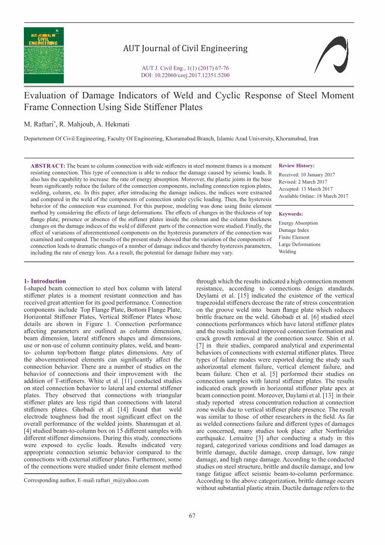
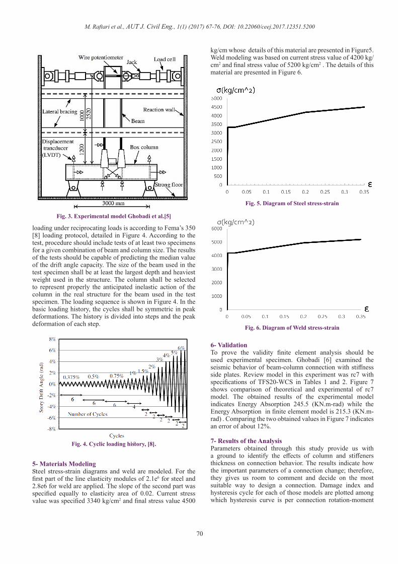
8- Effect of top flange plate thickness on damage indicesThe effect of top flange plate thickness change on damage indices parameters is initially investigated. As Figure 6 shows, where no continuity plate is used, then top flange plate thickness reduction in bottom flange plate weld to beam causes triaxiality stress index (Figure 10) as well as pressure stress increase (Figure 9) which results in probability of increased brittle failure whereas stiffener presence reduces the value as much as 15% while causing reduced brittle failure occurrence. Width reduction causes a slight increase in equivalent plastic strain conforming to Figure 11. These small changes lead to the slight increase in ductile and brittle failure. Top flange plate thickness reduction causes 38% increase in rupture probability in the weld,;furthermore, in the presence of continuity plate, the probability is reduced by 55% . In the case of no continuity plate, Figure 13 indicates that top flange plate thickness reduction causes triaxiality and Figure 14 indicates pressure stress indices reduction at top flange plate weld to the beam. There is still brittle failure probability while with continuity plate, triaxiality index reduces as much as 75% and brittle failure probability is eliminated; moreover, Figure 15 showing 25% reduction in
equivalent plastic strain index in this area indicates brittle or soft failure. Eventually, Figure 16 presents 15% reduction in rupture index that occurs as a result of top flange plate width reduction in the absence of continuity plate while at its presence a substantial reduction of 26% is reported.
9- Effect of column thickness on damage indicesFigures 17 and 18 show that the increase in column plate thickness, lowers triaxiality indices and pressure stress in top flange plate weld to the column which means reduced brittle failure probability; moreover, Figure 19 shows equivalent plastic strain index reduction as an indicator for brittle or ductile failure potential reduction. According to Figure 20, rupture index reduction in this area implies positive column thickness effect in weld behavior. The reduction was as much as 20% with no continuity plate and 54% with the continuity plate.
Fig. 7. compare the hysteresis behavior of models
Fig. 8. formation plastic hinge in beam
Fig. 9. Pressure stress index in top flange plate weld
Fig. 10. Triaxiality index in top flange plate weld
Fig. 11. PEEQ index in top flange plate weld
M. Raftari et al., AUT J. Civil Eng., 1(1) (2017) 67-76, DOI: 10.22060/ceej.2017.12351.5200
72
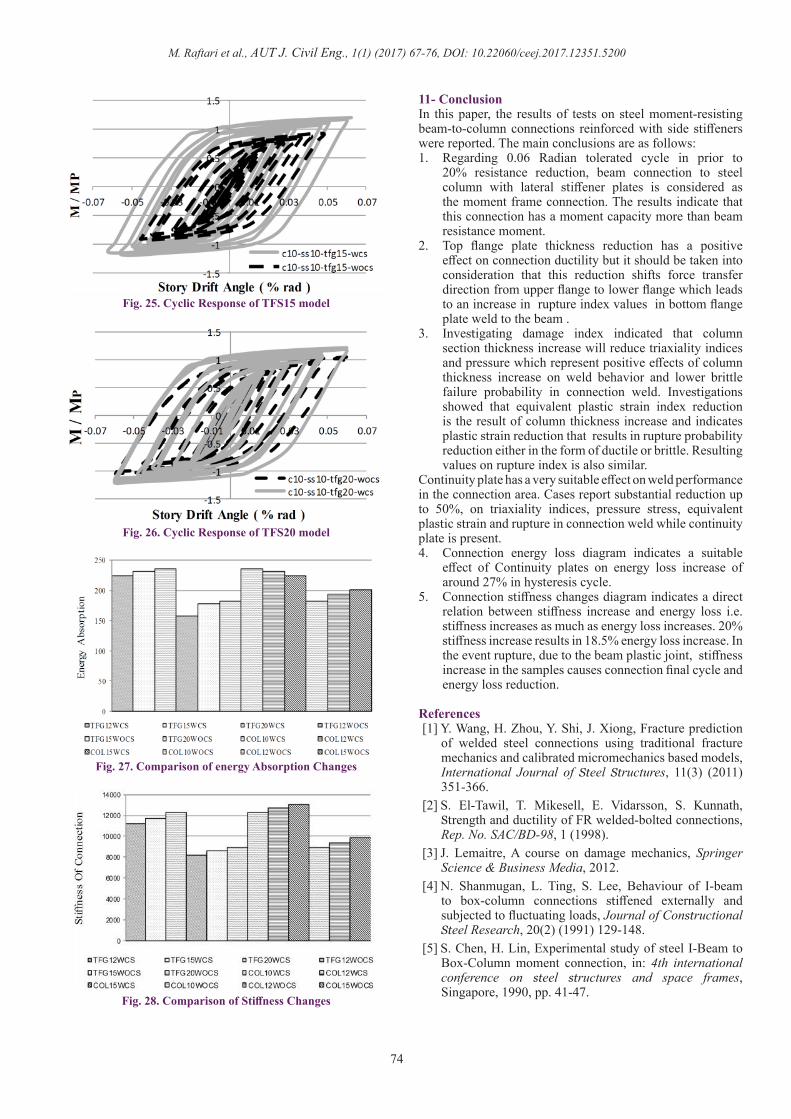
10- Connection hysteresis behavior analysisConnection cyclic behavior study indicates column continuity plate positive effect on connection performance. The presence of continuity plate results in increased connection stiffness that creates a positive effect on connection weld and leads to increased connection resistance and energy loss. In the following hysteresis figures, resulting moment values are equivalent to beam plastic moment. Figure 21 diagrams present the effects of use or non-use of continuity plate on hysteresis cycle which results in increased stiffness and connection resistance in column C10-WCS & C10-WOCS. In addition, Figure 22 indicates the top flange plate thickness changes affect connection cyclic behavior. Similarly, Figure 23 shows stiffness and connection resistance changes in C12-WCS & C12-WOCS models. Figure 23 demonstrates connection hysteresis behavior In C15-WCS & C15-WOCS models. This figures visible the positive impact column thickness changes on the behavior of connect hysteresis. Figures 24 to 26 show the impact of the absence of plate stiffeners on the behavior of connection hysteresis with top flange plate thickness of 12mm. Due to these shapes improve the seismic behavior of connection is visible. Figures 27 and 26 present a detailed comparison of the effect of column section and top flange plate thickness changes, with or without continuity plate. These diagrams show that in the absence of continuity plate, a reduction in top flange plate width will lower energy absorption as much as 4% while connection stiffness reduction is 5%. When continuity plate is present, there would be 30% increase in energy loss and 37% increase in connection stiffness. Moreover, column section width increase without continuity plate which results in 4% energy loss and 6% stiffness increase while in comparison with the presence of continuity plate, 19% energy loss and 36% stiffness increase were reported. It is notable that column sample with section thickness of 12 mm is plastic-joined to beam continuity plate at 34 th cycle and column sample with a section width of 15 mm is a plastic joined to beam continuity plate at 34th cycle and experience failure. In other cases, up to 36th cycle was tolerated by the beam. Finally, the table below shows the obtained values of the amount of energy absorption and stiffness of connection.
Fig. 12. Rupture index in top flange plate weld
Fig. 13. Triaxiality index
Fig. 14. Pressure stress index
Fig. 15. PEEQ index
Fig. 16. Rupture index

M. Raftari et al., AUT J. Civil Eng., 1(1) (2017) 67-76, DOI: 10.22060/ceej.2017.12351.5200
73
Fig. 17. Triaxiality stress index values
Fig. 18. Pressure stress index values
Fig. 19. PEEQ index values
Fig. 20. Rupture index values Fig. 24. Cyclic Response of TFS12 model
Fig. 23. Cyclic Response of C15 model
Fig. 22. Cyclic Response of C12 model
Fig. 21. Cyclic Response of C10 model
M. Raftari et al., AUT J. Civil Eng., 1(1) (2017) 67-76, DOI: 10.22060/ceej.2017.12351.5200
74
11- ConclusionIn this paper, the results of tests on steel moment-resisting beam-to-column connections reinforced with side stiffeners were reported. The main conclusions are as follows:1. Regarding 0.06 Radian tolerated cycle in prior to
20% resistance reduction, beam connection to steel column with lateral stiffener plates is considered as the moment frame connection. The results indicate that this connection has a moment capacity more than beam resistance moment.
2. Top flange plate thickness reduction has a positive effect on connection ductility but it should be taken into consideration that this reduction shifts force transfer direction from upper flange to lower flange which leads to an increase in rupture index values in bottom flange plate weld to the beam .
3. Investigating damage index indicated that column section thickness increase will reduce triaxiality indices and pressure which represent positive effects of column thickness increase on weld behavior and lower brittle failure probability in connection weld. Investigations showed that equivalent plastic strain index reduction is the result of column thickness increase and indicates plastic strain reduction that results in rupture probability reduction either in the form of ductile or brittle. Resulting values on rupture index is also similar.
Continuity plate has a very suitable effect on weld performance in the connection area. Cases report substantial reduction up to 50%, on triaxiality indices, pressure stress, equivalent plastic strain and rupture in connection weld while continuity plate is present.4. Connection energy loss diagram indicates a suitable
effect of Continuity plates on energy loss increase of around 27% in hysteresis cycle.
5. Connection stiffness changes diagram indicates a direct relation between stiffness increase and energy loss i.e. stiffness increases as much as energy loss increases. 20% stiffness increase results in 18.5% energy loss increase. In the event rupture, due to the beam plastic joint, stiffness increase in the samples causes connection final cycle and energy loss reduction.
References[1] Y. Wang, H. Zhou, Y. Shi, J. Xiong, Fracture prediction
of welded steel connections using traditional fracture mechanics and calibrated micromechanics based models, International Journal of Steel Structures, 11(3) (2011) 351-366.
[2] S. El-Tawil, T. Mikesell, E. Vidarsson, S. Kunnath, Strength and ductility of FR welded-bolted connections, Rep. No. SAC/BD-98, 1 (1998).
[3] J. Lemaitre, A course on damage mechanics, Springer Science & Business Media, 2012.
[4] N. Shanmugan, L. Ting, S. Lee, Behaviour of I-beam to box-column connections stiffened externally and subjected to fluctuating loads, Journal of Constructional Steel Research, 20(2) (1991) 129-148.
[5] S. Chen, H. Lin, Experimental study of steel I-Beam to Box-Column moment connection, in: 4th international conference on steel structures and space frames, Singapore, 1990, pp. 41-47.
Fig. 25. Cyclic Response of TFS15 model
Fig. 26. Cyclic Response of TFS20 model
Fig. 27. Comparison of energy Absorption Changes
Fig. 28. Comparison of Stiffness Changes

M. Raftari et al., AUT J. Civil Eng., 1(1) (2017) 67-76, DOI: 10.22060/ceej.2017.12351.5200
75
[6] M. Ghobadi, M. Ghassemieh, A. Mazroi, A. Abolmaali, Seismic performance of ductile welded connections using T-stiffener, Journal of Constructional Steel Research, 65(4) (2009) 766-775.
[7] K.-J. Shin, Y.-J. Kim, Y.-S. Oh, T.-S. Moon, Behavior of welded CFT column to H-beam connections with external stiffeners, Engineering Structures, 26(13) (2004) 1877-1887.
[8] S.J. Venture, G.D. Committee, Recommended seismic design criteria for new steel moment-frame buildings, Federal Emergency Management Agency, 2000.
[9] J. Hancock, A. Mackenzie, On the mechanisms of ductile failure in high-strength steels subjected to multi-axial stress-states, Journal of the Mechanics and Physics of Solids, 24(2-3) (1976) 147-160.
[10] S.W. Code-Steel, American Welding Society, Miami, Fla, (2004) 175-180.
[11] R.N. White, P.J. Fang, Framing connections for square structural tubing, Journal of the Structural Division,
92(2) (1966) 175-194.[12] AISC, Specification for Structural Steel Buildings;
American Institute of Steel Construction, in, Inc, 2005.[13] A. Deylami, A. Toloukian, Effect of Geometry of
Vertical Rib Plate on Cyclic Behavior of Steel Beam to Built-up Box Column Moment Connection, Procedia Engineering, 14 (2011) 3010-3018.
[14] M. Ghobadi, A. Mazroi, M. Ghassemieh, Cyclic response characteristics of retrofitted moment resisting connections, Journal of Constructional Steel Research, 65(3) (2009) 586-598.
[15] A. Deylami, M. Salami, Retrofitting of Moment Connection of Double-I Built-Up Columns using Trapezoidal Stiffeners, Procedia Engineering, 14 (2011) 2544-2551.
[16] J. Ricles, C. Mao, L. Lu, J. Fisher, Development and evaluation of improved ductile welded unreinforced flange connections. SAC Joint Venture, Sacramento, Calif. 2000; Rep. No, SAC/BD-00/24.
Please cite this article using:
M. Raftari, R. Mahjoub, A. Hekmati, “Evaluation of Damage Indicators of Weld and Cyclic Response of Steel
Moment Frame Connection Using Side Stiffener Plates”, AUT J. Civil Eng., (1) (2017) 67-76.
DOI: 10.22060/ceej.2017.12351.5200