Embed Size (px)
Citation preview
Proceedings of CHT-04
ICHMT International Symposium on Advances in Computational Heat Transfer
April 19-24, 2004, Norway
CHT-04-110
EVALUATION OF AN APPROXIMATE METHOD FOR PREDICITING THE U-VALUE OF A WINDOW WITH A BETWEEN-PANES LOUVERED SHADE
D. Naylor*, M. Collins**
*Dept. of Mechanical & Industrial Engineering, Ryerson University, Toronto, Ontario, Canada M5B 2K3
**Dept. of Mechanical Engineering, University of Waterloo, Ontario, Canada N2L 3G1
*Correspondence Author: Fax: 1 (416) 979-5267 Email: [email protected]
ABSTRACT A numerical model has been developed of the conjugate convection, conduction and radiation heat transfer in a double glazed window with a between-panes venetian-type blind. The two-dimensional finite-volume model has been validated for a range of slat angles using U-Value measurements from the open literature. This "Full CFD Model" has been used to show that the thermal performance of the window/blind enclosure can be closely approximated using a much simpler model. The "Simplified Model" combines data from a convection-only CFD solution with a six-surface radiation model. For both standard (high-e) and low-e windows, it has been shown that the Simplified Model can predicted the U-Value of the window/blind enclosure to within 1.5 percent, compared to the Full CFD Model. It has also been shown that the Simplified Model can account for geometric effects, such as the blind being located off the centre line of the gas-filled enclosure. Air was the fill gas in all calculations.
INTRODUCTION Recently, several commercial fenestration products have come onto the market that integrate a louvered blind between the panes of a double-glazed window. However, these products appear to be designed primarily based on aesthetics, rather than on thermal performance considerations. The current numerical study examines the interaction of a louvered blind with the free convection and longwave radiative heat transfer between the panes of a window. The goal is to develop accurate models of these interactions. With these models it may be possible to optimise the thermal performance of the complete blind/glazing unit. Several previous studies have examined the problem of a louvered (venetian-type) blind inside a vertically oriented double glazed window. Garnet [1] and Garnet et al. [2] have made a set of high accuracy measurements of the U-Value using a guarded heater plate apparatus. Measurements were made for range of slat angles and glazing spacings with an aluminum blind. These experimental data will be used in the current study to validate the numerical model. Some previous efforts have also been made to model this problem numerically. Garnet [1] developed a finite-volume CFD model of his experimental setup, which included 49 louvers in an enclosure with a height-to-width ratio of 34. However, severe convergence problems were
encountered and only a limited set of results were obtained (for the blind slats in the horizontal position). Ye [3] was successful in developing a finite element CFD model, with a much smaller computational domain. Ye obtained solutions for a short vertical window (with 19 louvers and an aspect ratio of 10). Recently, Yahoda and Wright [4] have presented a simple one-dimensional model for predicting the thermal resistance of a double-glazed window with a between-panes louvered blind. Their model combined a grey-diffuse radiation model with an empirical correlation for convection in a tall vertical enclosure. The predicted U-Values were within 10 to 15 percent of the experimental U-Value data of Garnet [1], despite the crude approximation used for the convection coefficients. The current study is, in some ways, an extension of the work of Yahoda and Wright [4]. In the present study, a two-dimensional CFD model is developed to study the conjugate conduction, convection and radiative heat transfer in a window with a between-panes venetian blind. Numerical results are obtained both with and without the effects of thermal radiation. The primary object of the current study is to demonstrate that the U-Value of the window/blind enclosure can be obtained accurately without the need to include thermal radiation in the CFD model. It will be shown that CFD results that exclude radiation effects can be subsequently combined with a simple radiation model to obtain the overall U-Value with sufficient accuracy for most window design purposes. This is an important result, since radiation modelling greatly increases the computational overhead. Also, the ability to "decouple" thermal radiation significantly reduces the number of variables in the CFD solution. Hence, this work is a logical precursor to a more complete CFD study of this geometry, which will include the effects of key parameters (such a Rayleigh number, cavity aspect ratio, dimensionless slat pitch, etc.) on the average Nusselt number.
PROBLEM FORMULATION & NUMERICAL SOLUTION
The problem geometry and coordinate system is shown in Figure 1(a). The window consists of a vertical enclosure formed by the inside surface of two window panes (spaced a distance S apart) and two end spacers. The glazing surfaces are approximated as isothermal and the end walls are assumed to be adiabatic. The blind consists of a set of evenly spaced louvers (at pitch P), which can be rotated about their centre points to an angle φ.
The flow is assumed to be steady, laminar incompressible and two-dimensional. All thermophysical properties are assumed constant, except for fluid density which is treated by means of the Boussinesq approximation. With these assumptions, the governing equations for the fluid are:
0yv
xu =
∂∂+
∂∂ [1]
∂∂+
∂∂µ+
∂∂−=
∂∂+
∂∂ρ 2
2
2
2
yu
xu
xp
yuv
xuu [2]
( )C2
2
2
2
TTgy
vx
vyp
yvv
xvu −βρ+
∂∂+
∂∂µ+
∂∂−=
∂∂+
∂∂ρ [3]
∂∂+
∂∂=
∂∂+
∂∂ρ 2
2
2
2
p yT
xTk
yTv
xTuc [4]
Gray-diffuse radiation exchange between the window and blind has been considered, with the assumption that the fill gas is a non-participating medium. For an enclosure consisting of N surfaces the radiosity of the kth surface (Jk) can be expressed in terms of the radiosities of the other N surfaces, as follows [5]:

Figure 1. (a) Model geometry and coordinate system, (b) Dimensions of the window/blind model in millimetres, corresponding to Garnet's experiment [1].
∑∑==
ε−+σε=ρ+=N
1jjkjk
4kk
N
1jjkjkkk JF)1(TJFEJ [5]
where Ek is the emissive power of the surface k, εk is the hemispherical emissivity of surface k, ρk is the reflectivity of surface k and Fkj is the view factor from surface k to surface j. Equation (5) represents N equations for the N surface radiosities. The effect of steady conduction in the blind slats has also be included. In solid regions, the temperature field is given by:
0yT
xT
2
2
2
2
=∂∂+
∂∂ [6]
At the blind-fluid interfaces, no slip and impermeability conditions are applied. In addition to a continuity of temperature, continuity of heat flux is also applied at these interfaces, expressed as follows:
RadFluid
FSolid
B qnTk
nTk ′′+
∂∂−=
∂∂− [7]
where n is the normal vector to the surface, kB and kF are the solid (blind) and fluid conductivities and q"Rad is the local radiative heat flux from the surface. Air was the fill gas in all cases (Prandtl number, Pr=0.717). The governing equations have been solved using the general purpose CFD software FLUENT. The numerical scheme was based on the control-volume formulation with the SIMPLEC algorithm (Van

Doormal and Raithby [6]) and a second-order upwind scheme for evaluation of the convective terms.
COMPARISON WITH EXPERIMENTAL DATA
The numerical model has been validated by comparison with the overall thermal resistance measurements of Garnet [1], which were made using a guarded heater plate apparatus (GHP). In order to understand the procedure used to make these comparisons, some description of the experiment is needed: Garnet's GHP apparatus consisted of a hot-side and cold-side copper plates, which were maintained at constant temperatures by a circulating fluid supplied from constant temperature baths. For the measurements, an insulated glazing unit with a between-panes venetian blind was "sandwiched" between these copper plates. In addition, thin sheets of neoprene were placed between the copper plates and the outer glass surfaces to reduce contact resistance. The GHP apparatus gives a highly accurate measurement of the total heat flux (q") through the test specimen, from copper plate to copper plate. In order to determine the thermal resistance associated with the window/blind assembly (Rwb), the resistance of the two neoprene sheets was subtracted from the total measured resistance, as follows:
qqR2)TT(
R neocphpwb ′′
′′⋅−−= [8]
where Thp and Tcp are the measured temperatures of the hot and cold copper plates and Rneo is the thermal resistance of one neoprene sheet. In Garnet's experiment the hot plate was maintained at Thp= 293 K and the cold plate was maintained at Thp= 273 K. The thickness and conductivity of the neoprene sheet was tneo=1.66 mm, kneo=0.2052 W/mK (Rneo=8.09x10⁻³ Km2/W). As is customary, the overall U-Values for the complete window/blind assembly reported by Garnet included the indoor and outdoor film coefficients which were not present in the experiment. These additional thermal resistances were subsequently added to the window/blind resistance, as follows:
11
outwb1
intotal )hRh(U −−− ++= [9] The overall U-Values reported by Garnet were based on typical indoor and outdoor film coefficients of hin= 8 W/m2K and hout= 23 W/m2K. In should be noted that the glass and neoprene layers were not included as part of the present numerical model. Preliminary numerical tests showed that the heat transfer in these thin layers was highly one-dimensional. However, it was necessary to correct for the temperature drop across the glass and neoprene layers, so that the temperature difference across the air gap in the present numerical model would be identical to that used in Garnet's experiment. The inside surface temperature of the cold glazing (TC) and the inside surface temperature of the hot glazing (TH) were calculated as follows:
)RR(qTT)RR(qTT
glassneohpH
glassneocpC
+′′−=
+′′+= [10]
where Rglass is the thermal resistance of the glass pane. In Garnet's experiment the thickness and conductivity of the glass was tglass=3.84 mm, kglass=0.96 W/mK (Rglass=4.0x10⁻³ Km2/W). For each

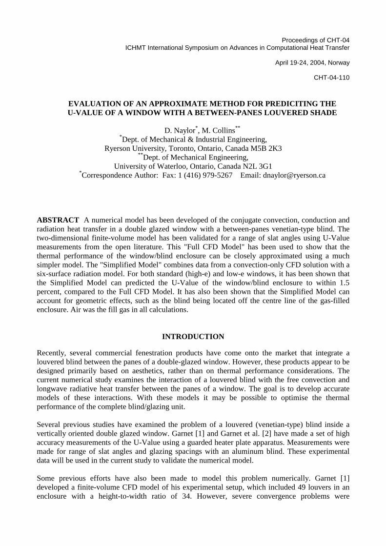
set of test conditions, the heat flux (q") was calculated from the U-Value reported by Garnet, using equations (8) and (9). The calculated glazing temperatures varied slightly from case to case; typically the cold glazing was maintained at a temperature of TC≈275 K and the hot glazing was maintained at TH≈292 K. The dimensions of the numerical window model were set to precisely match the experimental model of Garnet. The detailed dimensions are shown in Figure 1(b). The window had a height of H=604.5mm and a glazing spacing (air gap) of S=17.78 mm. The blind consisted of 49 aluminum slats (kal=120 W/mK) with width W=14.79 mm, thickness t=0.254 mm and pitch P=11.84 mm. The slat curvature was set based on measurements of commercially available blinds. The emissivity of the both windows (εw=0.84), the blind (εB=0.792) and end spacer walls (εs=0.86) was set to match Garnet's experiment. Table 1 shows a sample set of the results of grid testing for the present CFD model. In this table the overall heat transfer rate (q) is the average of the total heat transfer rates at the hot and cold glazings. In all cases, at convergence, an overall heat balance was achieved within 0.3 percent of the total heat transfer. As can be seen from Case 1 and Case 2, doubling the number of radiation surfaces in the radiation calculation changed the radiative heat transfer rates by less than 0.1 percent. In fact, it will be shown later (for the approximate model) that the number of radiation surfaces can be much smaller than used in these CFD calculations, without significantly degrading the predicted radiation heat transfer. So, we are confident that the number of sub-surfaces used in the current study is more than sufficient. Comparing Cases 2, 3 and 4 in Table 1 shows the sensitivity of the predicted heat transfer rates to the grid density. From Case 3 to Case 4, the number of nodes is approximately tripled, while keeping the number of radiation sub-surfaces nearly constant. The overall heat transfer rate across the window/blind system changed by only 0.11 percent and the radiative heat transfer rates changed by less than 0.5 percent. Based on the grid testing results, the typical grid used in this study consisted of approximately 100,000 nodes and 1300 sub-surfaces for the gray-diffuse radiation calculation. Figure 2 shows the numerically predicted temperature and stream function contours for slat angles of φ=0°, 45° and 75° at the conditions of Garnet's experiment. Figure 2(a) shows the temperature field in the entire computational domain for φ=0° to illustrate the extent of the window and the blind. Figures 2(b), (c) and (d) show only the upper and lower sections of the window and blind. It can be seen that, except near the top and bottom of the window, the temperature and flow field is
Table 1
Sample Grid Dependence Test Results for φ=45° (TH=292.0K, TC=274.3K, εH=0.84, εC=0.84, εB=0.792)
# of
Nodes # of RadiationSub-surfaces
Overall Heat Transfer Rate
q (W)
Hot Glazing Radiative HeatTransfer Rate
qrad,H (W)
Cold Glazing Radiative HeatTransfer Rate
qrad,C (W) Case 1 103,513 1353 50.871 26.995 -25.349 Case 2 103,513 677 50.894 26.978 -25.368 Case 3 54,565 637 50.867 26.929 -25.299 Case 4 148,645 682 50.923 27.019 -25.387
Figure 2. (a) Temperature field in the entire window enclosure for φ=0°, (b) Temperature (left) and stream function (right) contours for φ=0° (max. stream function ψmax=1.16x10⁻⁴ m2/s), (c) Temperature and stream function contours for φ=45° (max. stream function ψmax=1.43x10⁻⁴ m2/s), (d) Temperature and stream function contours for φ=75° (max. stream function ψmax=4.00x10⁻⁴ m2/s). strongly periodic. As given in the caption of this figure, the maximum stream function decreases by almost a factor of four when the slats are rotated from the nearly closed position (φ=75°) to the open position (φ=0°). So, the open blind significantly inhibits the free convective flow. This is a important issue from the perspective of flow stability, which will be discussed later. Figure 3 shows a comparison of the numerically predicted U-Value with the experimental results of Garnet [1]. As previously mentioned, these U-Values include the effect of film coefficients on the indoor and outdoor glazing surfaces, which Garnet assumed to be ho=23 W/m2K and hi=8 W/m2K. So, for the sake of direct comparison with Garnet, the current numerical results have been adjusted to included these additional thermal resistances, plus the resistance of the two glass panes. With these adjustments, the present numerical results are typically within 3 percent of the experimental measurements. Garnet estimates the uncertainty in the measured U-Values at ±1.1 percent, which is shown in the error bars in Figure 3.

Figure 3. Comparison of the present numerically predicted U-Value for various slat angles with the experimental measurements of Garnet [1]. "Slats Cold Side Up" corresponds to positive values of slat angle, φ. "Slats Hot Side Up" corresponds to negative values of slat angle, φ. It is interesting to note that Garnet found that the U-Value was slightly dependent on direction in which the blind was closed. In Figure 3, "Hot Side Up" means that the blind is closed such that highest edge of a tilted slat is on the side of the hotter glazing, corresponding to a negative value of φ. Conversely, "Cold Side Up" means that the highest edge of a tilted slat is on the side of the colder glazing, corresponding to a positive value of φ. Garnet found that the U-Values were slightly higher (by up to 6 percent at φ=+75°) when the blind slats were positioned cold side up rather than hot side up, at the same absolute slat angle. Garnet surmised that when the slats were angled cold side up, the blind would more readily deflect the rising warm air over to the cold glazing, thereby enhancing the convection. However, in the current numerical work, this effect was not observed. The U-Values for the blind closed hot side up and cold side up differed by less than 0.3 percent. If the cause of the 6 percent difference in the measured U-Value was the simple geometric effect postulated by Garnet, the current numerical model would almost certainly have confirmed this experimental result. It is interesting to note that a similar prior CFD study by Ye [3] of a short vertical window with a between-panes blind also found that the U-Value was unaffected by sign of the slat angle. Several attempts were made with the present numerical model to reproduce this effect of "blind closing direction", which has been repeatedly detected by Garnet; these included introducing perturbations in the precise horizontal position of the blind (consistent with those measured by Garnet) and small departures of the gravity vector from vertical. These attempts were unsuccessful. In all cases, at the same absolute value of slat angle |φ|, the direction in which the blind was closed had almost no effect on the numerically predicted U-Value. So, the cause of this small effect remains an interesting mystery. It may be that there was some small, but significant, difference in the geometry of Garnet's experimental setup and the current computer model. For example, it has been speculated that the suspended blind may have been displaced (slightly) off centre from its
original position by the free convective flow, when the temperature difference was applied to the guarded heater plate apparatus. This is conjecture and remains to be investigated. An important issue that should be discussed is the stability of the buoyancy-driven flow. For this complex geometry, there are presently no experimental data that would allow one to predict the onset of unsteady flow and the eventual transition to turbulence. However, the stability of flow in vertical enclosures has been studied extensively and can be used as a guide. For a tall vertical rectangular enclosure, the critical Grashof number for the onset of secondary cells is given by Korpela et al. [7] as:
+=A518000Grcrit [11]
where the Grashof number is based on the enclosure width (S) and A is the enclosure aspect ratio, A=H/S. Below this Grashof number the flow is unicellular. Above this Grashof number, a secondary flow exists, which consists of a regular pattern of co-rotating stationary cells along the vertical centre line of the enclosure. In recent experiments with large aspect ratio vertical enclosures, it has been observed that the transition to unsteady flow commences at Grashof numbers only slightly higher than this critical value [8]. For the present numerical study (and Garnet's experiment), the Grashof number was GrS = 1.6 x10⁴ and the aspect ratio was A= 34. This Grashof number is significantly above the critical Grashof number of Grcrit= 9.2x10³. So, in the absence of a blind, it would be questionable to assume steady laminar flow. However, when the blind is present, it is reasonable to assume that the blind will inhibit the flow to some extent, and will likely delay the onset of unsteady flow. This can be demonstrated by calculating the effective Rayleigh number when the blind is completely closed (φ=±90°), such that the window cavity is divided on the vertical centre line by the blind. In this hypothetical case, effective aspect ratio will be A=68 and the critical Grashof number for each "semi-enclosure" is Grcrit=8,625. The actual Grashof number (based on S/2 and (TH-TC)/2) for each "semi-enclosure" is Gr=1000, which is well into the steady conduction-dominated regime. Since configurations where the slats are partly open (φ>90°) are more restrictive to the buoyancy-driven flow than a completely closed blind (see Figure 2), it can be argued that the flow will probably remain steady and laminar for all slat angles. The validity of this argument is supported by the close agreement of the current numerical predictions with Garnet's measurements.
SIMPLIFIED MODEL
In this study, the "Simplified Model" corresponds to (i) convective heat transfer data from a convection-only CFD model of the system, combined with (ii) a simple six surface gray-diffuse radiation model.
Six surface radiation model The approximate radiant analysis is based on the assumptions that the blind slats have no curvature, are gray-diffuse in the longwave part of the spectrum, and can be represented by a single temperature. The array of slats is approximated as infinitely long, such that the radiative heat transfer is periodic. The periodic nature of the radiative heat flux is illustrated in Figure 4, which was calculated as part of the full CFD solution. This figure shows the local radiative heat flux from the hot glazing for φ=45° for the parameters corresponding to Garnet's [1] experiment. It can be seen that the radiative heat transfer is strongly periodic in the centre-glass region of the window. With the above assumptions, the window/blind geometry has been approximated as a six surface enclosure, as shown in Figure 5. In this figure, Surface 1 is the hot glazing and Surface 4 is the cold

Figure 4. Local radiative heat transfer rate on the hot glazing for φ=45° from the current CFD model (εH=0.84, εC=0.84, εB=0.792, TH=292.0 K, TC=274.3 K).
Figure 5. Six surface radiation model of the window and blind. glazing, Surfaces 2 and 3 are the upper slat and Surface 5 and 6 are the lower slat. In most blind installations, the blind pitch (P) is slightly less than the slat width (W), such that the blinds overlap in the closed position (φ→90°). Because of this overlap, it is necessary to divide both the upper and lower slats into two separate surfaces. Yahoda and Wright [4] have noted that the use of a four surface radiation model (where each slat surface is not sub-divided) will produce false transmittance at high slat angles, because of the overlap. For each calculation, the blind temperature (TB) was calculated iteratively based on the balance between radiative and convective heat transfer from the blind surface, which was modeled as:

)TT(Ph)TT(Phq BCBCBHBHB,Rad −+−= [12] where qRad,B is the net radiative heat transfer from one slat, hBH is the hot-side average heat transfer coefficient and hBC is the cold-side average heat transfer coefficient based on the glazing-to-blind temperature difference. In general, the heat transfer coefficient from the hot glazing to the blind will be different than the heat transfer coefficient from the cold glazing to the blind. The key approximation made in this study is that the convective resistances will be divided such that:
enclB
BCenclB
BH h1
h1,
h1)1(
h1 θ=θ−= [13]
where hencl is the heat transfer coefficient for the entire window/blind enclosure. The values of hencl and θB are obtained from a convection-only CFD solution, and are defined as:
CH
CBB
CH
convencl TT
TT,
)TT(Hq
h−−
=θ−
= [14]
where qconv is the overall convective heat transfer rate across the enclosure and θB is the average dimensionless blind temperature. When the blind is located at the centre of the enclosure, we expect θB≈0.5 for all slat angles and the convective resistance on each side of the blind will be approximately equal. However, when the blind is located off centre, the dimensionless blind temperature and the hot- and cold-side heat transfer coefficients will be substantially different. In this case, the total convective resistance across the enclosure (1/hencl) is considered to divide in direct proportion to the dimensionless blind temperature. It is assumed that the effects of radiation will have little effect on the these resistances. As will be shown in the Results section, this turns out to be an excellent approximation. For a known blind temperature, Equation (5) represents a set of simultaneous equations for the surface radiosities, with N=6. The radiation view factors for the six surfaces were calculated using Hottel's crossed-string method [9]. These equations were solved iteratively using the Bevans-Dunkle method [10]. In this iteration, the blind temperature (TB) was adjusted until the convective and radiative heat transfer rates at the blind surface were in balance, as given by Equation (12). To obtain the U-Value of the overall enclosure, the radiative heat transfer rates from the six surface radiation model are combined with convective heat transfer rates. The U-Value is calculated as:
)TT(P)TT(Phq
)TT(P)TT(Phq
UCH
BHBHH,Rad
CH
BCBCC,Radgg −
−+=
−−+
= [15]
where qRad,C and qRad,H are the radiative heat transfer rates from the cold and hot glazing surfaces over one blind pitch (P). The subscript "gg" has been added to emphasize that this U-Value from glazing-to-glazing and does not include the resistance of the glass panes nor the indoor/outdoor film resistances.
RESULTS Table 2 lists the convective heat transfer coefficients and average Nusselt numbers for the current window configuration calculated using the current CFD model, with radiation effects "turned off". With radiation effects omitted, this "convection-only CFD model" computes the free convection in the enclosure, which is coupled to the conduction in the aluminum blinds. The convective heat
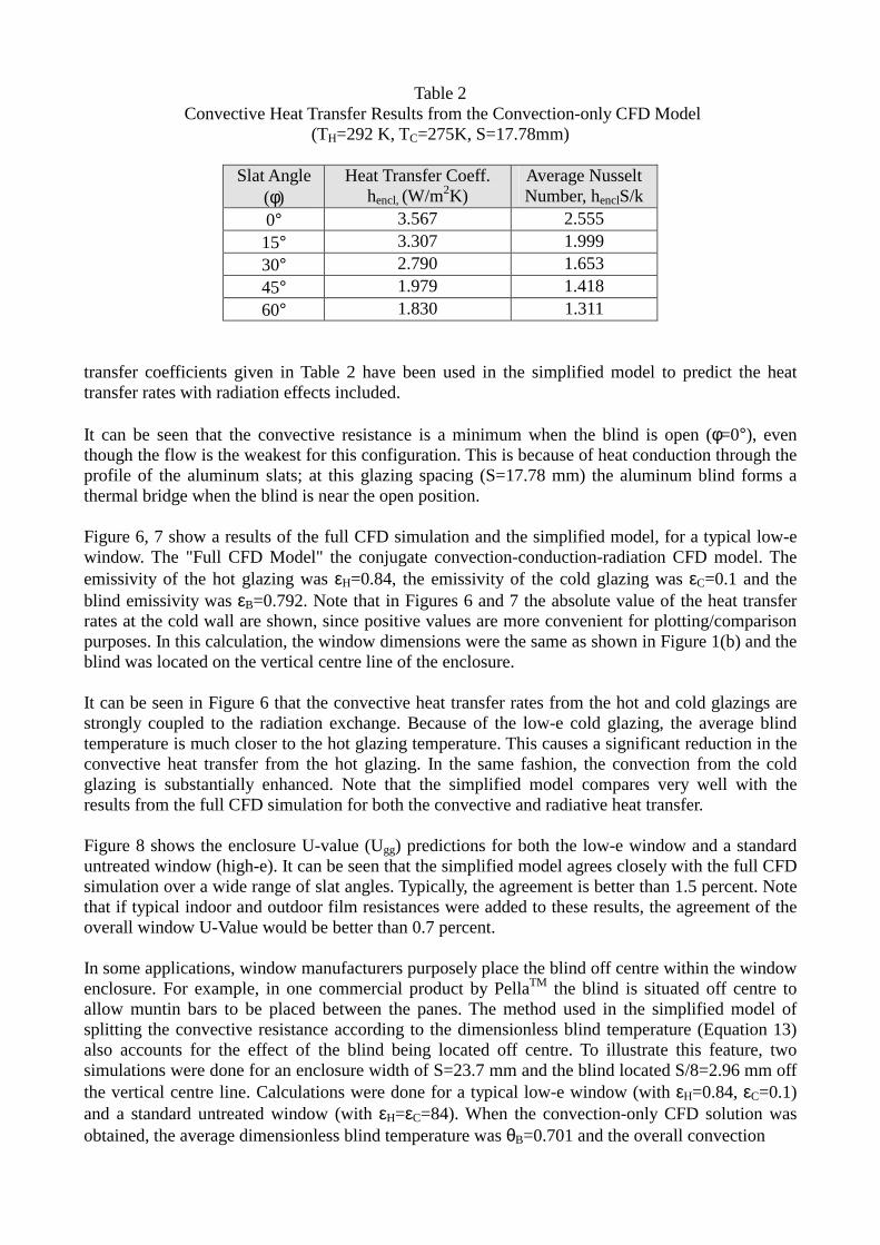
Table 2 Convective Heat Transfer Results from the Convection-only CFD Model
(TH=292 K, TC=275K, S=17.78mm)
Slat Angle (φ)
Heat Transfer Coeff. hencl, (W/m2K)
Average Nusselt Number, henclS/k
0° 3.567 2.555 15° 3.307 1.999 30° 2.790 1.653 45° 1.979 1.418 60° 1.830 1.311
transfer coefficients given in Table 2 have been used in the simplified model to predict the heat transfer rates with radiation effects included. It can be seen that the convective resistance is a minimum when the blind is open (φ=0°), even though the flow is the weakest for this configuration. This is because of heat conduction through the profile of the aluminum slats; at this glazing spacing (S=17.78 mm) the aluminum blind forms a thermal bridge when the blind is near the open position. Figure 6, 7 show a results of the full CFD simulation and the simplified model, for a typical low-e window. The "Full CFD Model" the conjugate convection-conduction-radiation CFD model. The emissivity of the hot glazing was εH=0.84, the emissivity of the cold glazing was εC=0.1 and the blind emissivity was εB=0.792. Note that in Figures 6 and 7 the absolute value of the heat transfer rates at the cold wall are shown, since positive values are more convenient for plotting/comparison purposes. In this calculation, the window dimensions were the same as shown in Figure 1(b) and the blind was located on the vertical centre line of the enclosure. It can be seen in Figure 6 that the convective heat transfer rates from the hot and cold glazings are strongly coupled to the radiation exchange. Because of the low-e cold glazing, the average blind temperature is much closer to the hot glazing temperature. This causes a significant reduction in the convective heat transfer from the hot glazing. In the same fashion, the convection from the cold glazing is substantially enhanced. Note that the simplified model compares very well with the results from the full CFD simulation for both the convective and radiative heat transfer. Figure 8 shows the enclosure U-value (Ugg) predictions for both the low-e window and a standard untreated window (high-e). It can be seen that the simplified model agrees closely with the full CFD simulation over a wide range of slat angles. Typically, the agreement is better than 1.5 percent. Note that if typical indoor and outdoor film resistances were added to these results, the agreement of the overall window U-Value would be better than 0.7 percent. In some applications, window manufacturers purposely place the blind off centre within the window enclosure. For example, in one commercial product by PellaTM the blind is situated off centre to allow muntin bars to be placed between the panes. The method used in the simplified model of splitting the convective resistance according to the dimensionless blind temperature (Equation 13) also accounts for the effect of the blind being located off centre. To illustrate this feature, two simulations were done for an enclosure width of S=23.7 mm and the blind located S/8=2.96 mm off the vertical centre line. Calculations were done for a typical low-e window (with εH=0.84, εC=0.1) and a standard untreated window (with εH=εC=84). When the convection-only CFD solution was obtained, the average dimensionless blind temperature was θB=0.701 and the overall convection
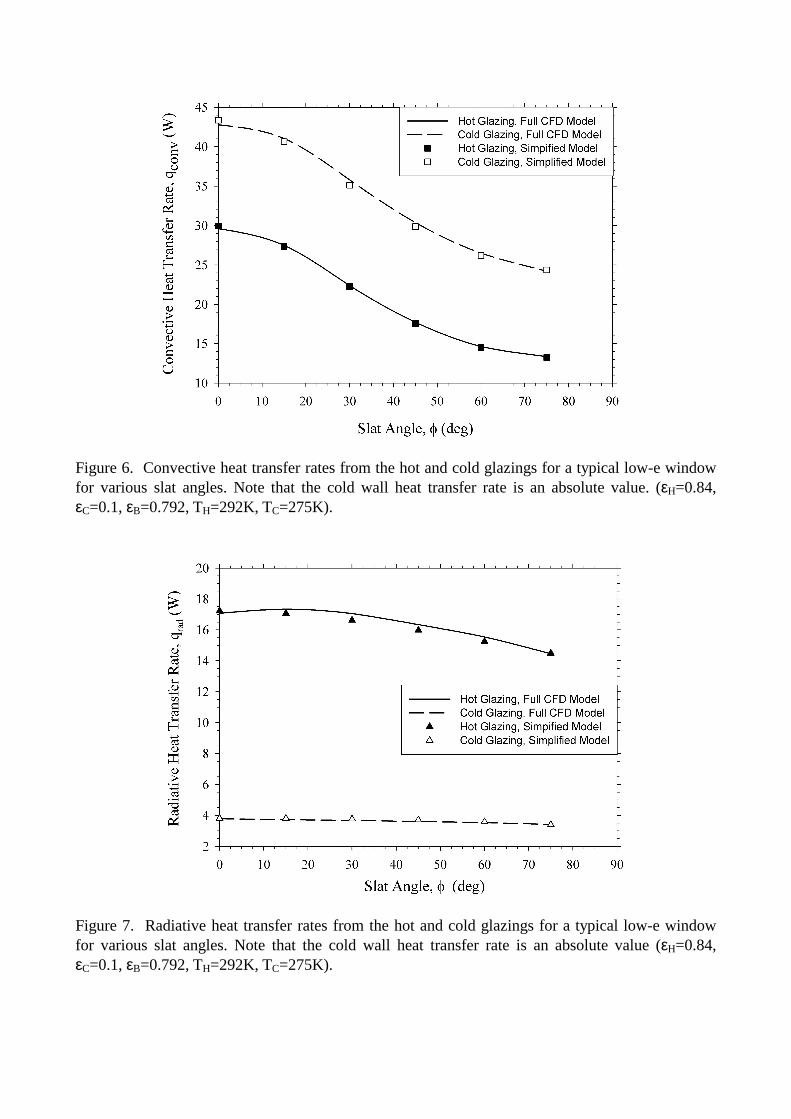
Figure 6. Convective heat transfer rates from the hot and cold glazings for a typical low-e window for various slat angles. Note that the cold wall heat transfer rate is an absolute value. (εH=0.84, εC=0.1, εB=0.792, TH=292K, TC=275K).
Figure 7. Radiative heat transfer rates from the hot and cold glazings for a typical low-e window for various slat angles. Note that the cold wall heat transfer rate is an absolute value (εH=0.84, εC=0.1, εB=0.792, TH=292K, TC=275K).
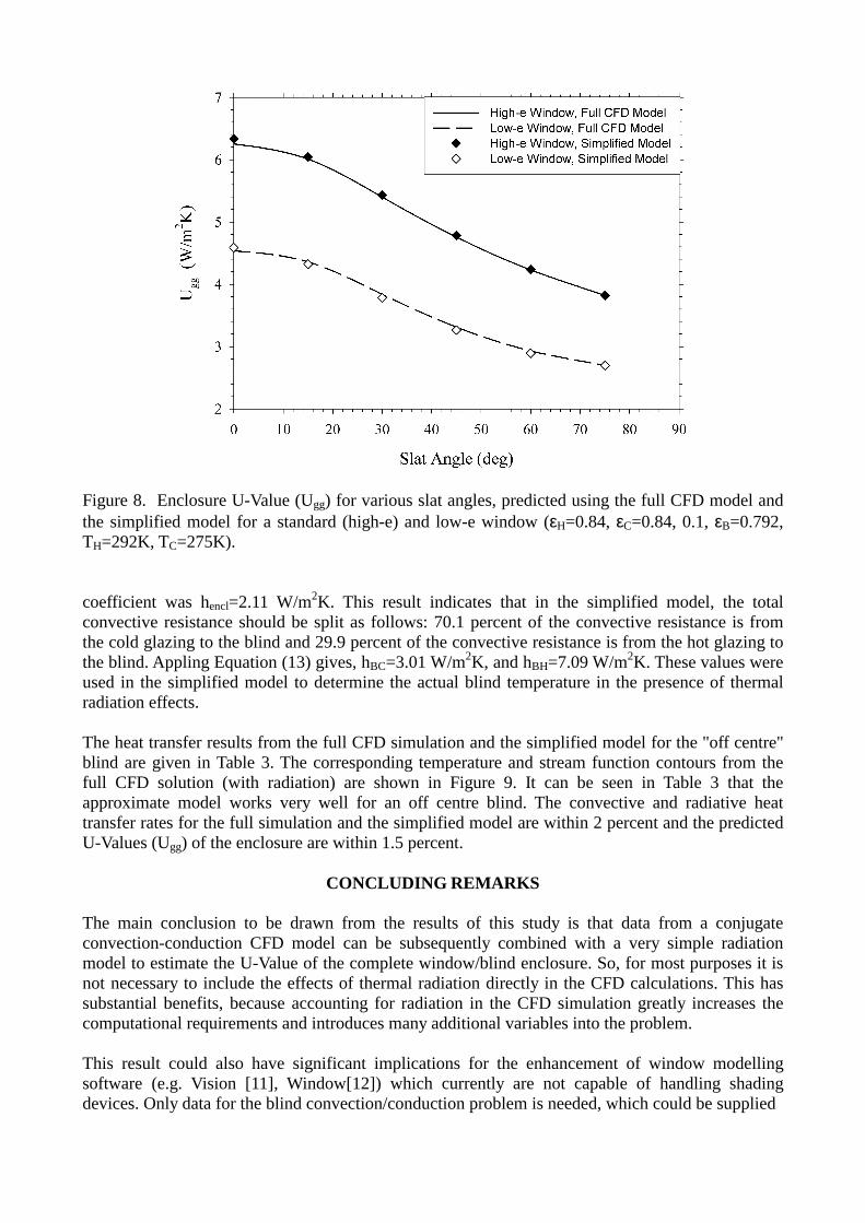
Figure 8. Enclosure U-Value (Ugg) for various slat angles, predicted using the full CFD model and the simplified model for a standard (high-e) and low-e window (εH=0.84, εC=0.84, 0.1, εB=0.792, TH=292K, TC=275K). coefficient was hencl=2.11 W/m2K. This result indicates that in the simplified model, the total convective resistance should be split as follows: 70.1 percent of the convective resistance is from the cold glazing to the blind and 29.9 percent of the convective resistance is from the hot glazing to the blind. Appling Equation (13) gives, hBC=3.01 W/m2K, and hBH=7.09 W/m2K. These values were used in the simplified model to determine the actual blind temperature in the presence of thermal radiation effects. The heat transfer results from the full CFD simulation and the simplified model for the "off centre" blind are given in Table 3. The corresponding temperature and stream function contours from the full CFD solution (with radiation) are shown in Figure 9. It can be seen in Table 3 that the approximate model works very well for an off centre blind. The convective and radiative heat transfer rates for the full simulation and the simplified model are within 2 percent and the predicted U-Values (Ugg) of the enclosure are within 1.5 percent.
CONCLUDING REMARKS
The main conclusion to be drawn from the results of this study is that data from a conjugate convection-conduction CFD model can be subsequently combined with a very simple radiation model to estimate the U-Value of the complete window/blind enclosure. So, for most purposes it is not necessary to include the effects of thermal radiation directly in the CFD calculations. This has substantial benefits, because accounting for radiation in the CFD simulation greatly increases the computational requirements and introduces many additional variables into the problem. This result could also have significant implications for the enhancement of window modelling software (e.g. Vision [11], Window[12]) which currently are not capable of handling shading devices. Only data for the blind convection/conduction problem is needed, which could be supplied
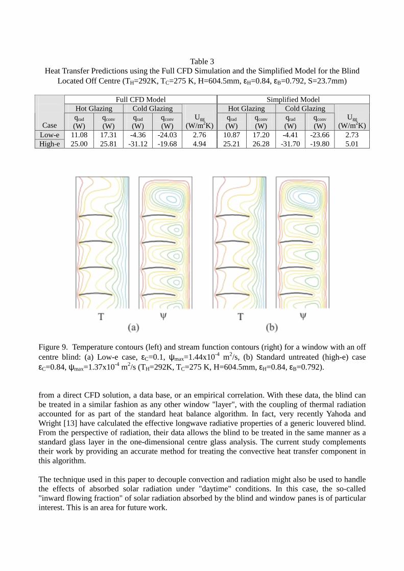
Table 3 Heat Transfer Predictions using the Full CFD Simulation and the Simplified Model for the Blind
Located Off Centre (TH=292K, TC=275 K, H=604.5mm, εH=0.84, εB=0.792, S=23.7mm)
Full CFD Model Simplified Model Hot Glazing Cold Glazing Hot Glazing Cold Glazing
Case qrad (W)
qconv (W)
qrad (W)
qconv (W)
Ugg
(W/m2K)qrad (W)
qconv (W)
qrad (W)
qconv (W)
Ugg
(W/m2K)Low-e 11.08 17.31 -4.36 -24.03 2.76 10.87 17.20 -4.41 -23.66 2.73 High-e 25.00 25.81 -31.12 -19.68 4.94 25.21 26.28 -31.70 -19.80 5.01
Figure 9. Temperature contours (left) and stream function contours (right) for a window with an off centre blind: (a) Low-e case, εC=0.1, ψmax=1.44x10⁻⁴ m2/s, (b) Standard untreated (high-e) case εC=0.84, ψmax=1.37x10⁻⁴ m2/s (TH=292K, TC=275 K, H=604.5mm, εH=0.84, εB=0.792). from a direct CFD solution, a data base, or an empirical correlation. With these data, the blind can be treated in a similar fashion as any other window "layer", with the coupling of thermal radiation accounted for as part of the standard heat balance algorithm. In fact, very recently Yahoda and Wright [13] have calculated the effective longwave radiative properties of a generic louvered blind. From the perspective of radiation, their data allows the blind to be treated in the same manner as a standard glass layer in the one-dimensional centre glass analysis. The current study complements their work by providing an accurate method for treating the convective heat transfer component in this algorithm. The technique used in this paper to decouple convection and radiation might also be used to handle the effects of absorbed solar radiation under "daytime" conditions. In this case, the so-called "inward flowing fraction" of solar radiation absorbed by the blind and window panes is of particular interest. This is an area for future work.

REFERENCES 1. Garnet, J.M., Thermal Performance of Windows with Inter-Pane Venetian Blinds, M.A.Sc. Thesis, University of Waterloo, Waterloo, Ontario, Canada, 1999. 2. Garnet, J.M., Fraser, R.A., Sullivan, H.F. and Wright, J.L., Effect of Internal Venetian Blinds on Window Centre-Glass U-Values, Window Innovations '95, Toronto, pp 273-279, 1995. 3. Ye, P., Effect of Venetian Blinds on Overall Heat Transfer Through Window Systems: A Finite Element Numerical Solution, M.Sc. Thesis, Queen's University, Kingston, Ontario, Canada, 1997. 4. Yahoda, D.S. and Wright, J.L., Heat Transfer Analysis of a Between-Panes Venetian Blind
using Effective Longwave Radiative Properties, ASHRAE Transactions, Vol. 101, Pt.1, in press, 2004.
5. Siegel, R., and Howell, J.R., Thermal Radiation Heat Transfer. McGraw-Hill, New York, 1972. 6. Van Doormal, J.P. and Raithby, G.D., Enhancement of the Simple Method for Predicting Incompressible Flows, Numerical Heat Transfer, Vol. 7, pp 147-163, 1984. 7. Korpela, S.A., Lee, Y. and Drummond, J.E., Heat Transfer Through a Double Pane Window, J. Heat Transfer, pp 539-544, 1982. 8. Jin, H., "Flow Visualization of Natural Convection in a Vertical Cavity", M.A.Sc. Thesis, University of Waterloo, Waterloo, Ontario, Canada, 2000. 9. Hottel, H.C. and Sarofim, A.F., Radiative Heat Transfer, McGraw-Hill, New York, 1967. 10. Wiebelt, J.A., Engineering Radiation Heat Transfer, Holt, Rinehart and Winston, Toronto, 1966. 11. Wright, J.L., and Sullivan, H.F., VISION3 Glazing System Thermal Analysis: Reference Manual, Advanced Glazing Laboratory, Department of Mechanical Engineering, University of Waterloo, Waterloo, Ontario, 1992. 12. Finlayson, E.U., Arasteh, D.K., Huizenga, C., Rubin, M.D., and Reilly, M.S., WINDOW: Documentation of Calculation Procedures, Energy and Environmental Division, Lawrence Berkeley Laboratory, Berkeley, California, 1993. 13. Yahoda, D.S. and Wright, J.L., Methods of Calculating the Effective Longwave Radiative
Properties of a Venetian Blind Layer, ASHRAE Transactions, Vol. 101, Pt.1, in press, 2004.