Embed Size (px)
Citation preview
1
Evaluation of a Test Case and Test Execution Model forDynamic Generation of Test Cases
By
Mats Olin, Carl Wykman
Submitted to the Department of Computer Science in partial fulfillment of therequirements for the degree of
Master of Science
LUND UNIVERSITY, FACULTY OF ENGINEERING
September 2007
Examiner:Per RunesonProfessor of Software EngineeringDepartment of Computer Science,Lund University, Faculty ofEngineering.
Supervisors:Jonas BengtssonSenior SpecialistEricsson AB
Niklas HagermanStaff engineerEricsson AB
Marcus TörndahlDevelopment EngineerEricsson AB

2
3
Abstract
The number of functions that are incorporated and used in mobile phones arecontinuously increasing, creating new demands for mobile platform testdevelopment and testing methods. To improve and facilitate testing and testcase derivation, a new patent filed test case and test execution model wasdeveloped at a large telecommunications company. This model combines amodularized approach to test cases with an ability to execute them in parallel,stand alone or in sequences.
This study presents an evaluation of this patent filed model in aspects of theautomation of concurrency test case derivation through executing test case inparallel. In order to conduct the evaluation an implementation of a prototypeof the model was created. The prototype enabled an exploratory investigationof the model for conducting actual tests on mobile platforms.
The results indicate that parallel execution of test cases can be used to createconcurrency test cases that more resemble the actual usage of the mobileplatform than a static execution of test cases permit. The study also indicatesthat different strategies in implementing test cases affect the level ofautomation achieved, in terms of their independency from each other duringparallel execution.

4
5
Acknowledgements
We would like to thank our supervisors at Ericsson, Jonas Bengtsson, NiklasHagerman and Marcus Törndahl for giving us the opportunity to perform ourmaster’s thesis in such an inspiring and developing environment as thetelecom industry is, and also send a special thanks for the help and guidanceyou have provided.
We would also like to thank our supervisor at LTH, Per Runeson, for hisinvolvement, valuable advises and inputs that has made the completion of thismaster thesis possible.
6
Contents1 Introduction.................................................................................. 71.1 Background.......................................................................................... 71.2 Objective............................................................................................... 81.3 Method.................................................................................................. 81.4 Outline ................................................................................................ 10
2 Theory ........................................................................................ 112.1 Software Engineering Basics............................................................ 112.2 Software Testing ................................................................................ 132.3 Brief overview of the testing process at SV-EMP ............................ 18
3 Test Case and Execution Model Principles............................. 233.1 S3C...................................................................................................... 233.2 ECB..................................................................................................... 243.3 Behavioral Model ............................................................................... 25
4 Model and Prototype Development.......................................... 284.1 The different parts of the S3C/ECB-Prototype ................................. 284.2 ECB-Tool ............................................................................................ 294.3 S3C-Script .......................................................................................... 334.4 S3C Connection Server ..................................................................... 384.5 The Test Execution Script ................................................................. 384.6 Aspects affecting the technical solution.......................................... 38
5 Evaluation and Discussion....................................................... 415.2 Achievement of overall goals for the original model....................... 465.3 Discussion.......................................................................................... 48
6 Conclusions and Future work .................................................. 496.1 Conclusions ....................................................................................... 496.2 Future work ........................................................................................ 49
AppendixUsing the S3C/ECB Prototype .......................................................... 50Distribution of work ........................................................................... 51Glossary.............................................................................................. 52References.......................................................................................... 55
7
1 Introduction
1.1 Background
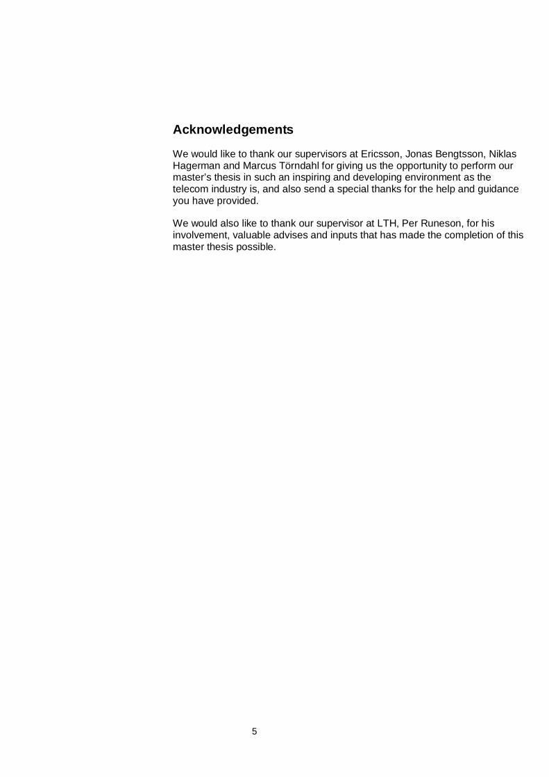
Ericsson Mobile Platforms (EMP) develop mobile platforms which areelectronic devises consisting of hardware and software. Mobile platforms areprimly used as the main electronic device in mobile phones. The pace atwhich new mobile platforms are released are continuously increasing at thesame time as the platforms are getting more and more complex with morefeatures and functions added. The number of possible concurrency situationsbetween the different functions in the platform is therefore dramaticallyincreasing over time. This is causing a demand for more test cases to bedeveloped to ensure good test coverage on new product releases. Today,concurrency testing is not performed to its full extent due to the large numberof possible permutations the concurrent testing of different functions resultsin. Since every test case needs to be designed and developed individually,creating concurrency test cases is resource demanding. The number ofconcurrency test cases in relation to the number of different functions on amobile platform is illustrated in the left box in Figure 1.
The structure of the test cases that are used at EMP today can be seen as asequential script with fixed sequence of actions. That means that aconcurrency test case always executes the same fixed concurrency scenario.While used in a mobile phone, the platform is exposed to different kinds ofconcurrency scenarios since most often, the concurrent functions are run asparallel independent processes. This is illustrated in the right box in Figure 1.
Figure 1. Background
Sequentially codedconcurrency test case. Thedifferentially colored boxessymbolizes test codetargeting different functionsin the platform.
Parallel executedfunctions. Each linesymbolizes a functionand executed togetherthey form a concurrencyscenario.
Number of Functions in the platform
Number of concurrency test casesneeded for full test coverage
8
1.2 Objective
The objective of this master’s thesis is to develop and evaluate a model, herecalled the S3C-Concept, for automating concurrency test case derivation. TheS3C-Concept is based on ideas from a patent pending called A Method And ASystem For Software Testing (P-21560) produced at the Department ofSystem Verification at Ericsson Mobile Platforms (SV-EMP). The evaluation isof an exploratory kind and requires an implementation of a prototype of themodel which will be used for conducting tests on mobile platforms. Thecondition for a successful project is a delivery of an evaluation that declareswhether the model is usable in SV-EMP’s test system or not.
1.3 Method
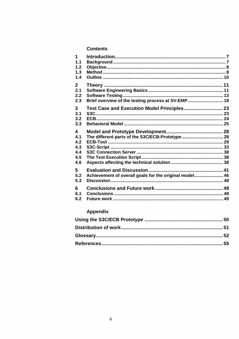
The implementation and evaluation of the patent filed model that forms thebasis of this master’s thesis is a broad task that can be carried out in anumber of iterations. The method used is action research which according toHöst et al (2006) contains of three main phases; observation, development ofsolution proposal and evaluation. In this case, the outcome of both theimplementation (solution proposal) and the evaluation in terms of softwareartifacts and conclusions are uncertain at the starting position. The goal forthe solution proposal phase is to implement a prototype that is functionalenough to be used in the evaluation, and to form a basis for furtherdevelopment. The work process for this master’s thesis is described in Figure2 and the different parts of the work process are described here below.
Figure 2. Work process for this master’s thesis
Pre-Study: The pre-study consists of a literature study to find out aboutexisting knowledge related to the assigned task within the field of test casegeneration, software testing and test automation in general. The pre-studyalso consists of a study of the patented model that is to be implemented andhow the patented model is related to the work process at SV-EMP.
9
Specification: The activities of the specification phase takes the patentedmodel from a conceptual idea to a software design. In further iterations of thedevelopment cycle described in Figure 2, the specification will be adjusteddepending on the results from previous implementation and evaluation. Sincethe development is of an experimental kind with many short iterations, noformal specifications are documented for each iteration.
Implementation: The implementation phase consists of creating softwareartifacts such as test cases, test scripts and parts of the test environmentaccording to the specification. These artifacts are then used as basis for anevaluation and either be discarded or developed further in future iterations ofthe development cycle.
Evaluation: The evaluation is aimed at investigating if and how the patentedmodel, or a further development of it, could be used in the testing activities atSV-EMP. The evaluation also aims to establish recommendations for atechnical solution that can be used in a large scale implementation. Theevaluation criterions are developed from information gained in the pre-study.The information comes from interviewing employees at SV-EMP working withtest development and test execution, and from general software qualitycharacteristics defined in the ISO 9126-1 quality model (2001). The testsystem quality measures that form the evaluation criteria and that are to betaken into consideration are:
• Stability of the test system
• Traceability for errors
• Enabling of creation of specific test scenarios
• Level of code re-use and possible savings of test case developmentresources
• Fault finding capability and Test Coverage
The evaluation will be performed by using the implemented model forexecuting test on mobile platforms and also while trying out different technicalsolutions for the implementation.
10
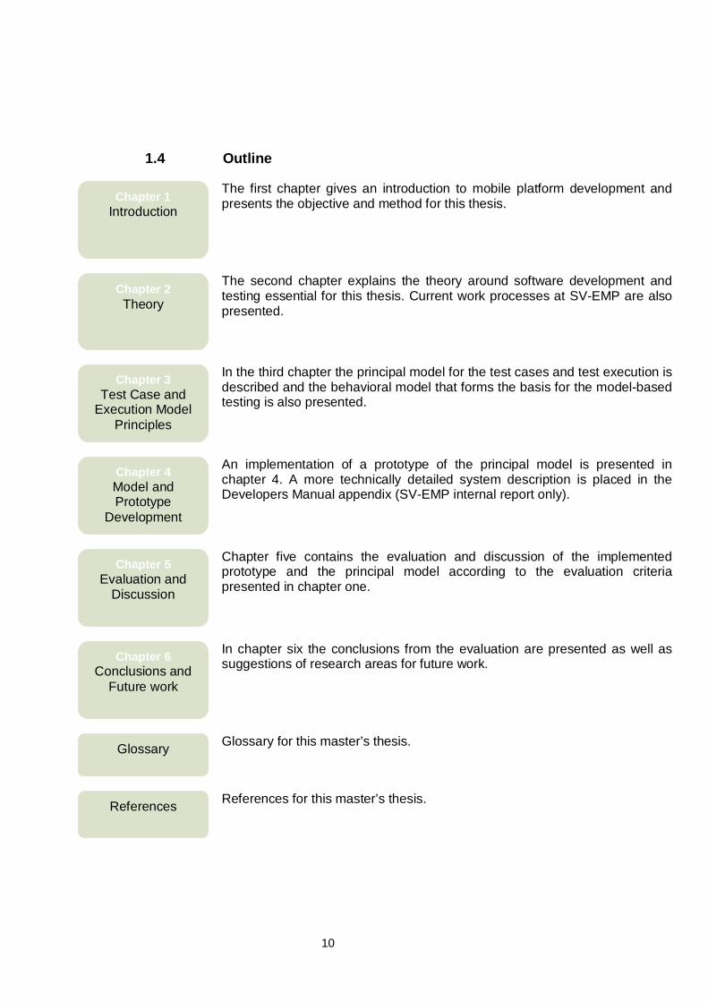
1.4 Outline
The first chapter gives an introduction to mobile platform development andpresents the objective and method for this thesis.
The second chapter explains the theory around software development andtesting essential for this thesis. Current work processes at SV-EMP are alsopresented.
In the third chapter the principal model for the test cases and test execution isdescribed and the behavioral model that forms the basis for the model-basedtesting is also presented.
An implementation of a prototype of the principal model is presented inchapter 4. A more technically detailed system description is placed in theDevelopers Manual appendix (SV-EMP internal report only).
Chapter five contains the evaluation and discussion of the implementedprototype and the principal model according to the evaluation criteriapresented in chapter one.
In chapter six the conclusions from the evaluation are presented as well assuggestions of research areas for future work.
Glossary for this master’s thesis.
References for this master’s thesis.References
Glossary
Chapter 6Conclusions and
Future work
Chapter 5Evaluation and
Discussion
Chapter 4Model andPrototype
Development
Chapter 3Test Case and
Execution ModelPrinciples
Chapter 2Theory
Chapter 1Introduction
11
2 Theory
The purpose of the theory chapter is to give a brief introduction to some of theexisting knowledge and theory that is used in this master’s thesis. The theorychapter consists of three different sections and starts of with the basicconcept of software engineering and a presentation of two commonly referredprocess models in 2.1. This section is then followed by 2.2 which deals withsoftware testing activities, automation and model-based testing which will bereferred to when describing the model in chapter 4 and also during theevaluation. Section 2.3 explains some of how the test system at SV-EMP isconstructed and also the work process they use for developing test cases.
2.1 Software Engineering Basics
Software testing is part of the larger scientific field of Software Engineering.Software engineering is the application of a systematic, disciplined,quantifiable approach to the development, operation, and maintenance ofsoftware (IEEE, 1990).
2.1.1 Software Engineering Process Models
The Waterfall Model
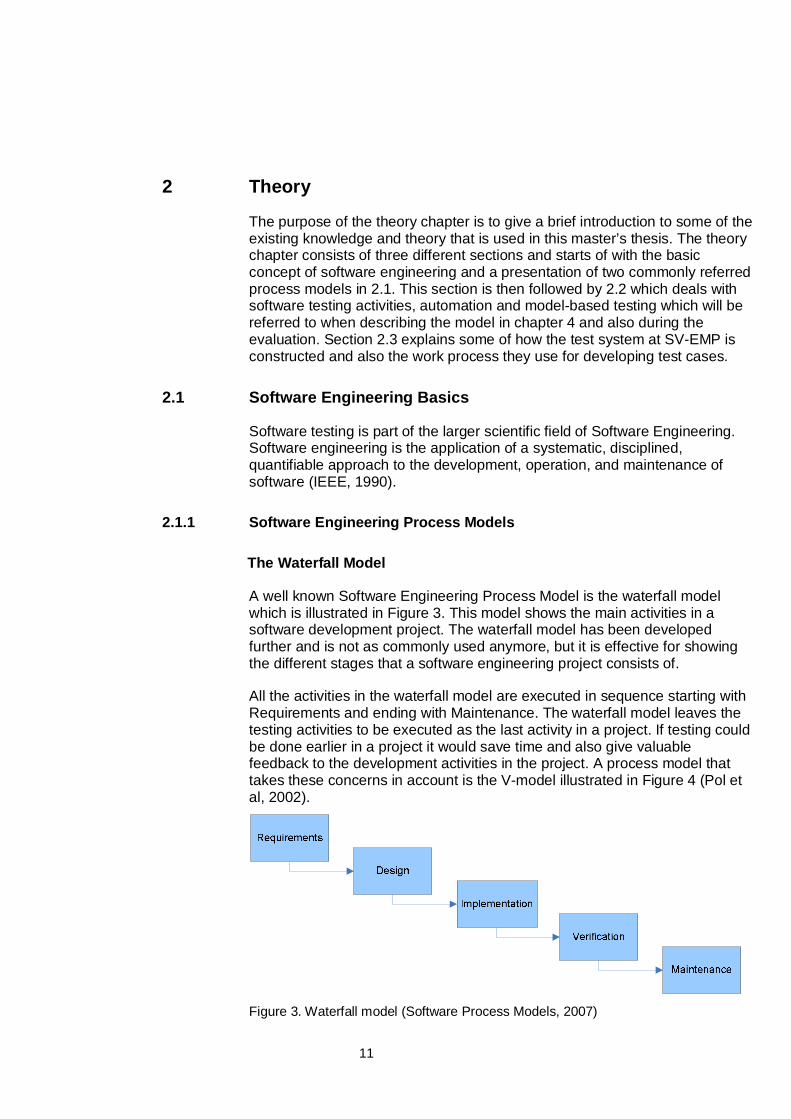
A well known Software Engineering Process Model is the waterfall modelwhich is illustrated in Figure 3. This model shows the main activities in asoftware development project. The waterfall model has been developedfurther and is not as commonly used anymore, but it is effective for showingthe different stages that a software engineering project consists of.
All the activities in the waterfall model are executed in sequence starting withRequirements and ending with Maintenance. The waterfall model leaves thetesting activities to be executed as the last activity in a project. If testing couldbe done earlier in a project it would save time and also give valuablefeedback to the development activities in the project. A process model thattakes these concerns in account is the V-model illustrated in Figure 4 (Pol etal, 2002).
Figure 3. Waterfall model (Software Process Models, 2007)
12
The V-Model
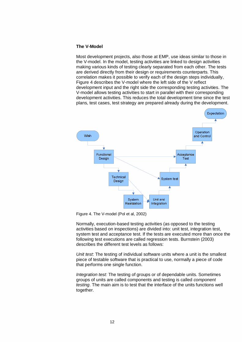
Most development projects, also those at EMP, use ideas similar to those inthe V-model. In the model, testing activities are linked to design activitiesmaking various kinds of testing clearly separated from each other. The testsare derived directly from their design or requirements counterparts. Thiscorrelation makes it possible to verify each of the design steps individually,Figure 4 describes the V-model where the left side of the V reflectdevelopment input and the right side the corresponding testing activities. TheV-model allows testing activities to start in parallel with their correspondingdevelopment activities. This reduces the total development time since the testplans, test cases, test strategy are prepared already during the development.
Figure 4. The V-model (Pol et al, 2002)
Normally, execution-based testing activities (as opposed to the testingactivities based on inspections) are divided into: unit test, integration test,system test and acceptance test. If the tests are executed more than once thefollowing test executions are called regression tests. Burnstein (2003)describes the different test levels as follows:
Unit test: The testing of individual software units where a unit is the smallestpiece of testable software that is practical to use, normally a piece of codethat performs one single function.
Integration test: The testing of groups or of dependable units. Sometimesgroups of units are called components and testing is called componenttesting. The main aim is to test that the interface of the units functions welltogether.
13
System test: The testing of a fully integrated system, where all units havebeen assembled to an operating system. System test evaluates bothfunctional behavior and quality requirements such as reliability, usability,performance and security.
Acceptance test: The system is run in presence of the customer or by thecustomer and is used to see if the system meets the customer requirements.
Regression test: The reruns of already executed tests due to changes of thetested software or other causes that requires a new verification of the system.
2.2 Software Testing
2.2.1 Test Activities
Software testing is, in a broad sense, the activity to evaluate the quality ofsoftware artifacts in terms of correctness, functionality, capability, efficiencyetc. This activity can be organized and conducted in different ways,depending on what is tested and the surrounding environment in which thetesting activities take place. One way to organize the testing suggested by Polet al (2002) is to divide software testing into five different phases:
• Planning
• Preparation
• Specification
• Execution
• Completion
All software testing projects should start with a planning phase, where goalsfor the testing and the strategy are set. After that follows a preparation phasein which documentation of the test objects is reviewed and techniques,infrastructure and test units are set. During the specification phase the testspecifications and other material such as scripts, scenarios and databasesare produced. In the execution phase the actual testing takes place and thetest outcome are analyzed. The last phase which is completion summarizesand evaluates the test outcome and the test process for future improvements.
This is just one way to divide the testing activities into a number of phaseswith certain deliverables such as documents or test scripts. It is up to everyorganization to form their own processes and make them fit their specificneeds and resources. In general, the phases resemble the ones in thewaterfall model (see Figure 3) with two additional boxes; one for testexecution and one for test evaluation and reporting. In the latter the testoutcome are collected. These activities are then looped and performed inmany iterations throughout the development cycle of the product that is to bedelivered.
14
2.2.2 Test Automation
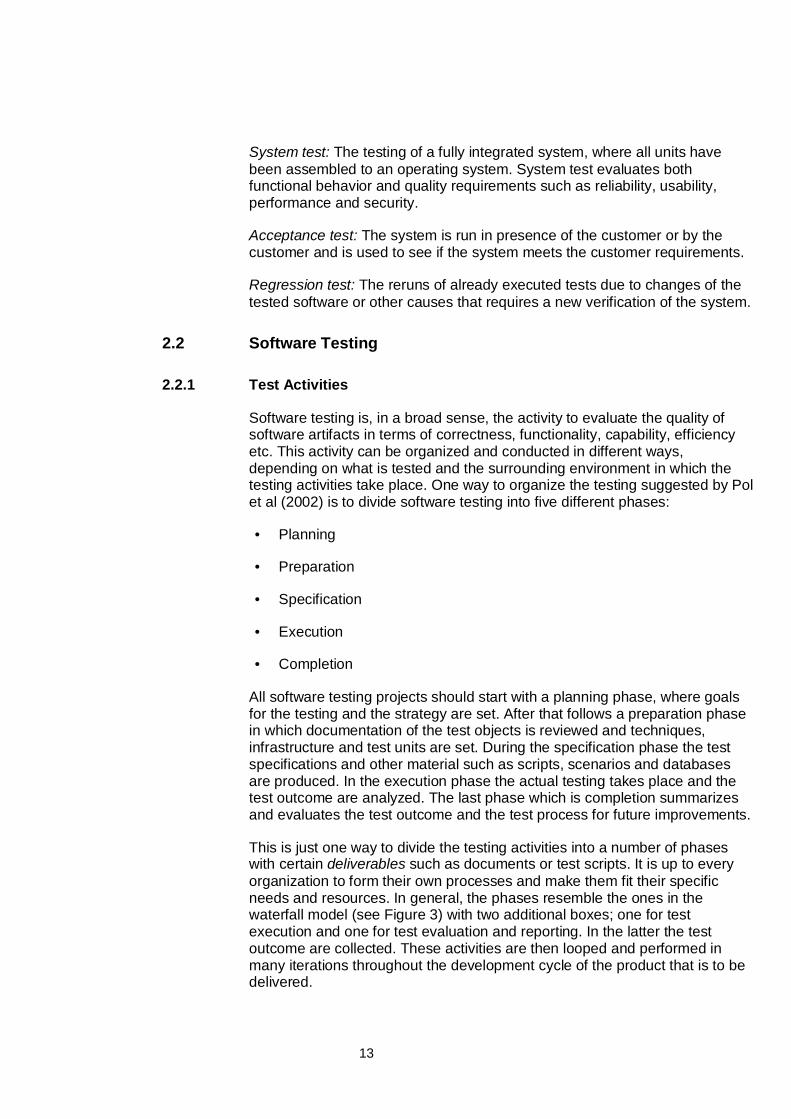
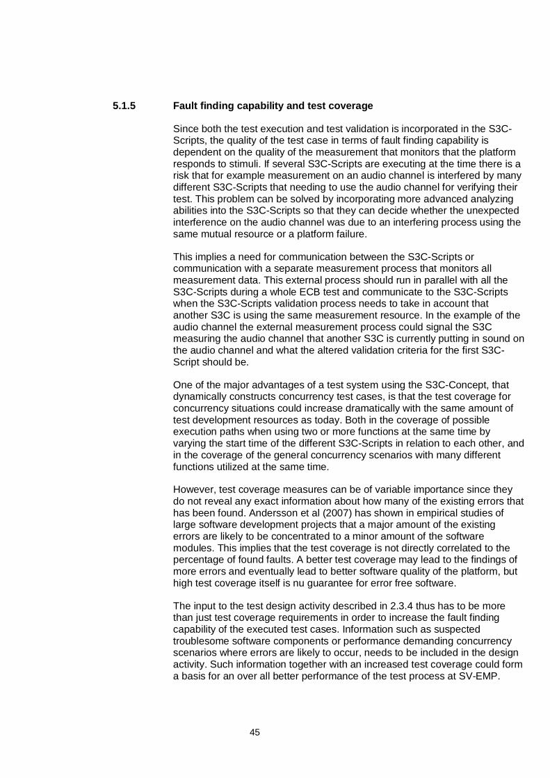
In order to rationalize software testing, testing activities throughout the testprocess has been automated. Fewster & Graham (1999) suggests that thetesting activities that are the most suitable for automation are the ones thatare performed most often, repetitive, simple and easy to structure. Figure 5shows an example of which activities that in the general case is the mostappropriate to automate.
Figure 5, Test activities and their ability to be automated (Fewster & Graham, 1999)
The first activity which is identifying strategies and establishing goals for thetesting is quite intellectual and not very repetitive. Therefore it is quite intuitivethat the activity is difficult to automate. The same goes for designing the testsystem and the structure of the test cases. Build, Execute and Check/Analysisare all activities that have potential to be performed more resource efficient ifthey are automated. Tasks within these activities could for example be testcase derivation (Build), test execution (Execute) and test outcome analysis(Check).
It is also important to realize that not all types of test cases are good or evenpossible to automate. Function and performance test cases are typically quiteeasy, but it might be difficult to automate tests concerning non-functionalqualities such as maintainability, usability, portability etc. That is becausethose tests often require human-computer interaction or more structuralanalysis of the system, which is an intellectual task rather than a clerical.
Intellectual
Performedonce
Repeatedmany times
Clerical
Identify
Design
Build
Execute
Check
15
Why Automate?
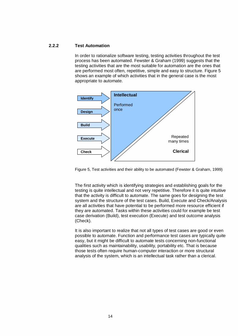
Fewster & Graham (1999) describe the decision of whether to automate a testcase or to perform it manually as a trade-off between economical andevolvable. What they mean is that an automated test case is moreeconomical than a manually executed test case after a number of testexecutions. The resources spent on development of an automated test caseshould be, in order to economically motivate automation, less than theresources spent on manual test execution. The drawback is that automatedtest cases often require more work when changed than manual test caseswhich makes them less evolvable.
Another measure of the quality of a test case is the consideration betweeneffective and exemplary. This relation is not affected by whether the test caseis automated or not. The four quality measures and their relation to automatedand manual test cases are illustrated in Figure 6 (Fewster & Graham, 1999).
Figure 6. Keviat diagram describing test case qualities (Fewster & Graham, 1999)
In SV-EMP’s case, most test cases are executed a large number of times inregression tests and are therefore suitable for automation. The problem ofautomated test cases not being evolvable is extra notable in the area ofconcurrency test. That is because concurrency test cases often consist ofmore code and concerns more functionality which might change between newversions of the software and hardware in the platforms. Because of the largenumber of regression tests and the technical nature of the device under test(DUT), the concurrency test cases still benefit from being automated. Also,each new release of a platform resembles the previous in the way that theOpen Platform API (OPA) between the platform and the customer application(see Figure 8) only has minor changes on existing functionality. This makes itpossible to re-use test cases from previous releases, increasing the lifespanof test software artifacts, and making automation of test cases moreeconomic.
Exemplary
Effective
EvolvableEconomic
Automated test(after many runs) Manual test
First run ofautomated
test
16
2.2.3 Model-Based Testing
Model based testing is a testing technique can be utilized and implemented inmany different ways. The basic idea according to Pretschner et al (2005) andBotincan et al (2007) is that a model that represents the system under test(SUT) is used to derive test cases that are used to test the SUT. The modelmust be more abstract than the SUT, otherwise a different system than theSUT would be specified by the model. The abstraction can be achieved in twoways:
• Encapsulation. The structure of the SUT is analyzed and described in amodel.
• Simplification. Details are removed in order to achieve a more abstractand manageable representation of the SUT.
This means that this testing technique can not be used to test the details ofthe SUT but rather generate test cases that test the SUT’s general structureand functionality. In the context of this thesis the general structure could bethat a certain functionality on a mobile platform such as starting a Bluetoothsession can be performed at the same time as a voice call is connected. Sucha test does not focus on the details or variations of either the Bluetoothfunctionality or the voice call functionality but it test that both functions can beused at the same time.
According to Katara et al (2006) model-based testing can be seen as a part ofmodel-driven development. Model-driven development is a technical methodfor software development where the level of abstraction is raised from manualcoding into automatically generating code (as well as tests) from structuraland behavioral models. The instigating factor for model-driven development isto save resources spent on system development by automatically generatingcode.
A sub genre of model-driven development is domain-specific modeling thatraises the level of abstraction beyond manual coding by specifying thesolution directly using domain concepts (DSM Forum, 2007). This means thatthe compiler that generates the code should be specifically designed tofunction in a certain domain, for example at SV-EMP for creating test casesfor mobile platforms.
According to Katara et al (2006) there are two types of models:
• Structural model: A model that describes the system from the basis ofhow it is constructed and intended to function.
• Behavioral model, A model that focuses on the actual utilization of thesystem rather than what is theoretically possible based on the systemsstructure.
17
Model representations can be used to generate code by compiling the modelin the same way as high level programming languages are compiled intoassembler code. The model can be represented either graphically or asstructured text. Similar, a model can be used to generate test cases, eitherfrom structural or from behavioral models. If the code is generated from thesame model as the test cases, the tests become more like testing the modelscompiler which might not be relevant or equivalent to what needs to be tested.One possible solution is to have separate models for development and testsand for example use a behavioral model to generate the test cases and astructural to generate the system. The model has to be developed to fit thespecific testing requirements for each system.
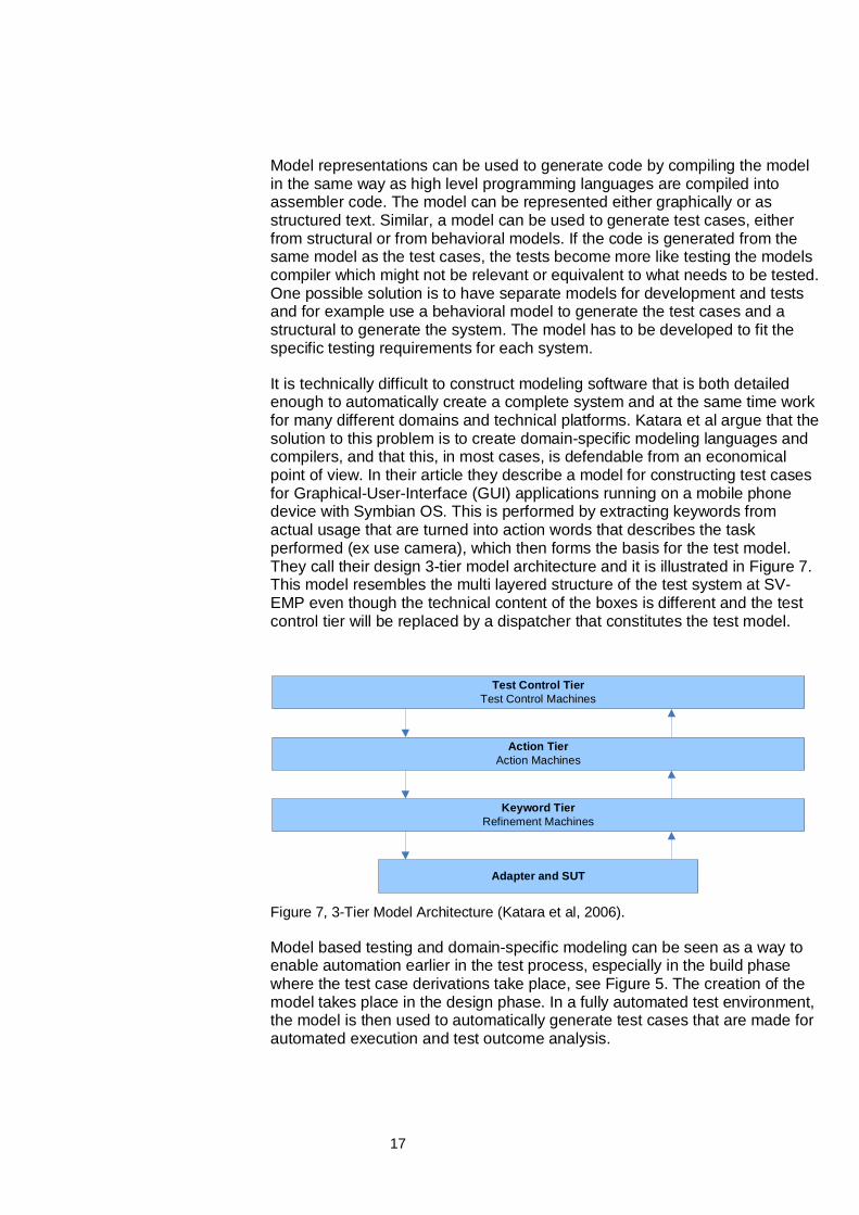
It is technically difficult to construct modeling software that is both detailedenough to automatically create a complete system and at the same time workfor many different domains and technical platforms. Katara et al argue that thesolution to this problem is to create domain-specific modeling languages andcompilers, and that this, in most cases, is defendable from an economicalpoint of view. In their article they describe a model for constructing test casesfor Graphical-User-Interface (GUI) applications running on a mobile phonedevice with Symbian OS. This is performed by extracting keywords fromactual usage that are turned into action words that describes the taskperformed (ex use camera), which then forms the basis for the test model.They call their design 3-tier model architecture and it is illustrated in Figure 7.This model resembles the multi layered structure of the test system at SV-EMP even though the technical content of the boxes is different and the testcontrol tier will be replaced by a dispatcher that constitutes the test model.
Test Control TierTest Control Machines
Action TierAction Machines
Keyword TierRefinement Machines
Adapter and SUT
Figure 7, 3-Tier Model Architecture (Katara et al, 2006).
Model based testing and domain-specific modeling can be seen as a way toenable automation earlier in the test process, especially in the build phasewhere the test case derivations take place, see Figure 5. The creation of themodel takes place in the design phase. In a fully automated test environment,the model is then used to automatically generate test cases that are made forautomated execution and test outcome analysis.
18
2.3 Brief overview of the testing process at SV-EMP
2.3.1 Test Automation at SV-EMP
All test execution and outcome analysis performed at SV-EMP are more orless automated. This means that the once the test cases are startedmanually, they execute, perform the outcome analysis and verifies if theypass or fail automatically. A few test cases needs manual verification that isperformed by the tester. The actions in the use cases (UC) are transformedinto test cases and then automated on a computer connected to the mobilephone being tested. A mobile phone can roughly be separated into two parts:One part is the mobile platform developed by EMP, which is composed of thehardware and software needed to operate all functionalities in the phone. Thisis also described in see Figure 8 in 2.3.2. The other part is the applicationsoftware placed in the application layer, the application software is developedby EMP’s customers. The application software is the software that creates auser interface and connects the user’s actions with the mobile platform toform a mobile phone. This can be compared to an application running on apersonal computer. The application software interacts with the mobileplatform on which it is executed on, through an interface called OPA. It is theapplication software’s usage of OPA that SV-EMP tests when verifying thefunctionality of the mobile platform.
Testing is usually performed with no manual involvement by the tester, exceptfor starting the test-cases and registering if it passes or fails. The test casesare implemented using LabVIEW™ which also is used for execution and testoutcome analysis of the test cases. Most of the test execution is conducted ata regression test site separated from the test case development. At theregression site they receive new versions of the software together with a listof test cases to be run in a prioritized order. Most test cases are startedmanually although some might be initiated by a script so that they can runtests over night.
If a test case fails the tester does a preliminary investigation of what wentwrong by reading log-files and measurement data. Then the tester creates anIncident Report (IR), this IR is assigned to a person responsible forinvestigating why the incident occurred, normally a test developer. The testdeveloper analyzes the IR and either corrects the test case or assigns the IRto a developer if it is a platform failure (IRs can also be dismissed withoutaction if they are deemed unimportant.)
19
Sometimes a test case fails during one test execution and then passes atanother test execution testing the same software. The reason for that couldbe external circumstances such as problem with the connection between thetelephone and the base station. This is a source for instability in the testsystem and causes problems since it is the tester’s choice to decide whetherthere is a defect in the software that caused the occasional failure, or if it wasbecause of external circumstances. An incident report will only be reported ifthe tester decides that the test case failure was not caused by externalcircumstances. From an automation point of view, it is very important that thetest cases needs as little manual involvement as possible and minimize theamount of failures caused by external circumstances as possible. A goodsolution to the problem would be if the test cases could recognize failurescaused by external circumstances and report that to the test system.
2.3.2 Automated Test Case Platform Architecture
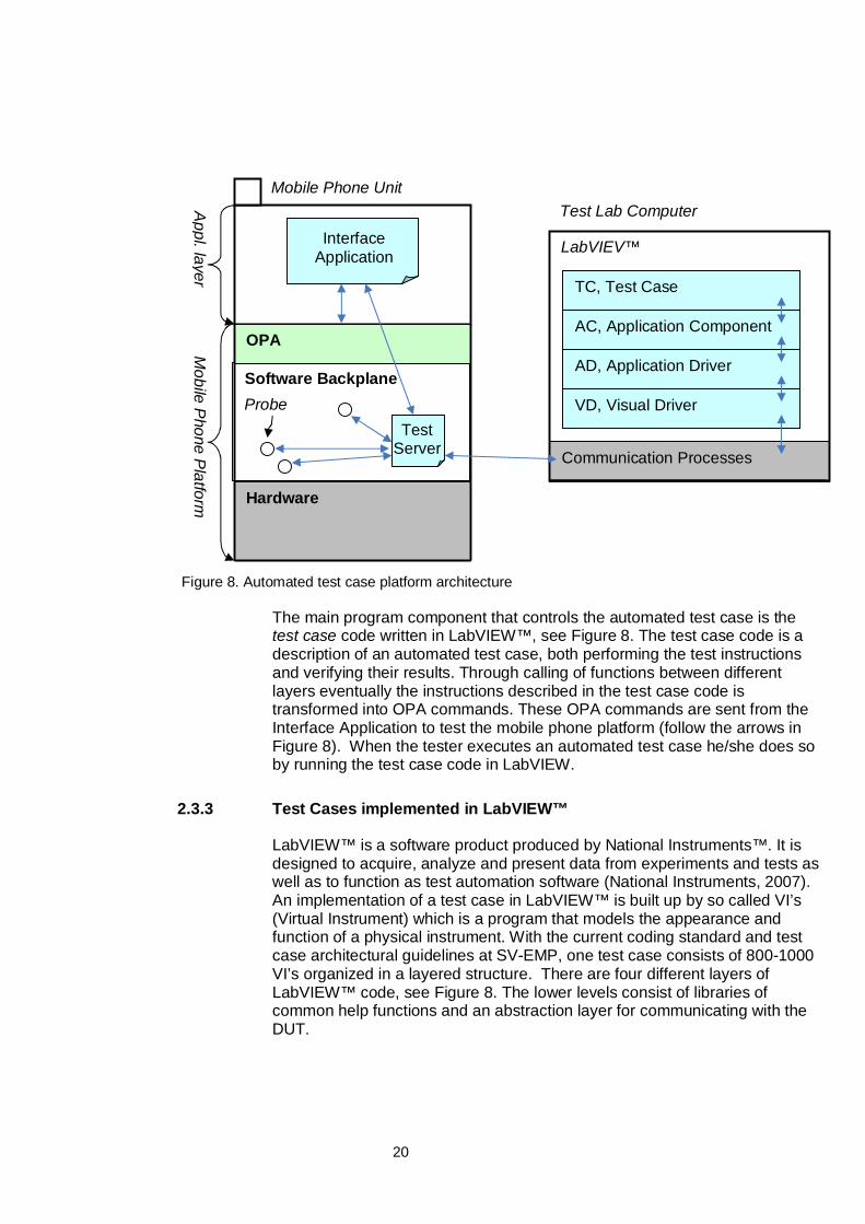
As can be seen in Figure 8 the Interface Application software is the softwarethat communicates with the OPA. This is the same way that the customerapplication communicates with OPA. The Interface Application is developedespecially for testing and enables automated test cases at SV-EMP toperform the testing of the platform. The input data needed to perform testcases is injected either through probes or through an audio channelconnected to the phones audio-in connector. The output from the mobileplatform that is needed to verify the test cases is collected through probesand the recording of audio from the DUTs audio out connector. The probesthat are used can be described as signals sending information about whatcode is executed in the Software Backplane. Probes are also used forinjecting data into the executing code. The Software Backplane handles allfunctionalities that the mobile platform supports and can be compared to anoperating system for a mobile phone.
20
Figure 8. Automated test case platform architecture
The main program component that controls the automated test case is thetest case code written in LabVIEW™, see Figure 8. The test case code is adescription of an automated test case, both performing the test instructionsand verifying their results. Through calling of functions between differentlayers eventually the instructions described in the test case code istransformed into OPA commands. These OPA commands are sent from theInterface Application to test the mobile phone platform (follow the arrows inFigure 8). When the tester executes an automated test case he/she does soby running the test case code in LabVIEW.
2.3.3 Test Cases implemented in LabVIEW™
LabVIEW™ is a software product produced by National Instruments™. It isdesigned to acquire, analyze and present data from experiments and tests aswell as to function as test automation software (National Instruments, 2007).An implementation of a test case in LabVIEW™ is built up by so called VI’s(Virtual Instrument) which is a program that models the appearance andfunction of a physical instrument. With the current coding standard and testcase architectural guidelines at SV-EMP, one test case consists of 800-1000VI’s organized in a layered structure. There are four different layers ofLabVIEW™ code, see Figure 8. The lower levels consist of libraries ofcommon help functions and an abstraction layer for communicating with theDUT.
Software Backplane
OPA
InterfaceApplication
TestServer
TC, Test Case
AC, Application Component
AD, Application Driver
VD, Visual Driver
LabVIEV™
Communication Processes
Mobile P
hone Platform
Mobile Phone UnitTest Lab Computer
ProbeHardware
Appl. layer
Probe
21
During execution of a test case LabVIEW™ follows an execution line whichcontains the actions to be performed as well as a surveillance of the expectedsystem responses in order to determine whether the test case has failed andshould be terminated or if it is ok and ready to continue.
2.3.4 An overview of how SV-EMP develops automated tests
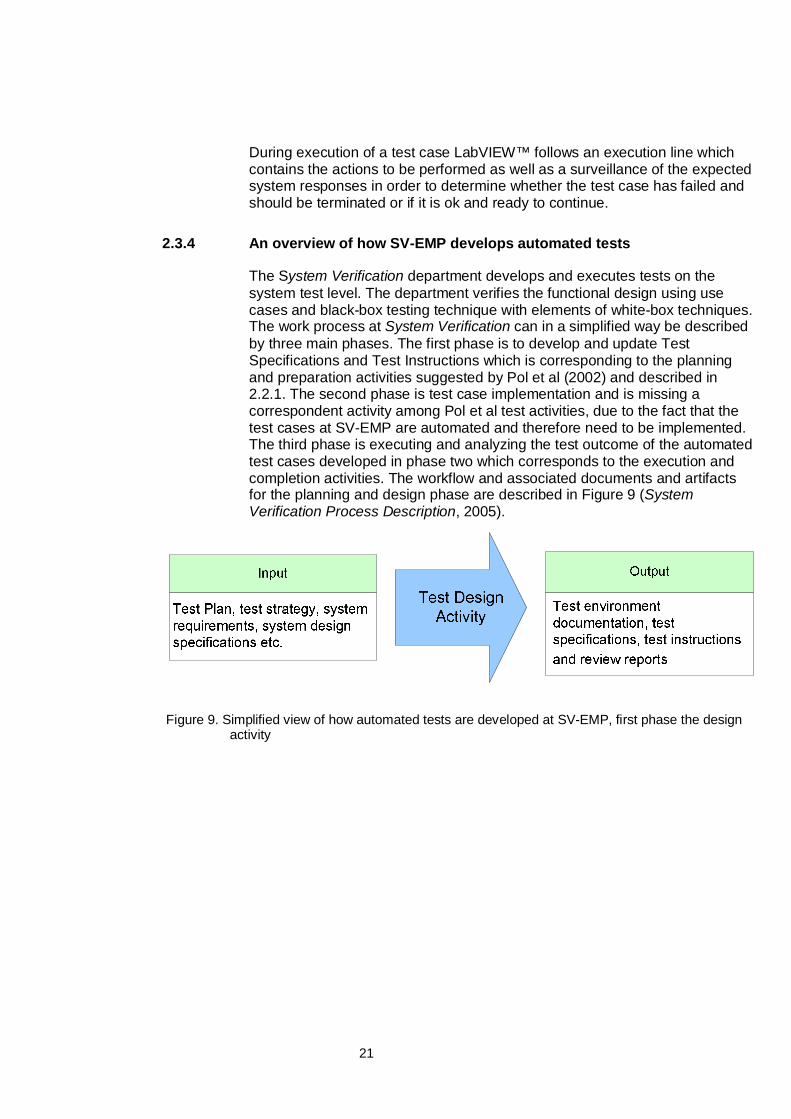
The System Verification department develops and executes tests on thesystem test level. The department verifies the functional design using usecases and black-box testing technique with elements of white-box techniques.The work process at System Verification can in a simplified way be describedby three main phases. The first phase is to develop and update TestSpecifications and Test Instructions which is corresponding to the planningand preparation activities suggested by Pol et al (2002) and described in2.2.1. The second phase is test case implementation and is missing acorrespondent activity among Pol et al test activities, due to the fact that thetest cases at SV-EMP are automated and therefore need to be implemented.The third phase is executing and analyzing the test outcome of the automatedtest cases developed in phase two which corresponds to the execution andcompletion activities. The workflow and associated documents and artifactsfor the planning and design phase are described in Figure 9 (SystemVerification Process Description, 2005).
Figure 9. Simplified view of how automated tests are developed at SV-EMP, first phase the designactivity
22
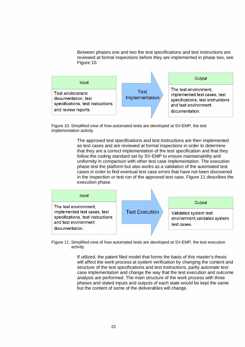
Between phases one and two the test specifications and test instructions arereviewed at formal inspections before they are implemented in phase two, seeFigure 10.
Figure 10. Simplified view of how automated tests are developed at SV-EMP, the testimplementation activity
The approved test specifications and test instructions are then implementedas test cases and are reviewed at formal inspections in order to determinethat they are a correct implementation of the test specification and that theyfollow the coding standard set by SV-EMP to ensure maintainability anduniformity in comparison with other test case implementation. The executionphase test the platform but also works as a validation of the automated testcases in order to find eventual test case errors that have not been discoveredin the inspection or test run of the approved test case. Figure 11 describes theexecution phase.
Figure 11. Simplified view of how automated tests are developed at SV-EMP, the test executionactivity.
If utilized, the patent filed model that forms the basis of this master’s thesiswill affect the work process at system verification by changing the content andstructure of the test specifications and test instructions, partly automate testcase implementation and change the way that the test execution and outcomeanalysis are performed. The main structure of the work process with threephases and stated inputs and outputs of each state would be kept the samebut the content of some of the deliverables will change.
23
3 Test Case and Execution Model Principles
This master’s thesis is based on a filed patent called A Method And A SystemFor Software Testing (P-21560) which was developed at SV-EMP in 2005-2006. The realization of the concept and the ideas in the patent are calledSelf-Contained Container Concept and will be referred to as the S3C-Conceptfurther on.
The S3C-Concept consists of two parts; a description of a Self-ContainedContainer (S3C) and a description of an Execution Control Block (ECB).Together they form a model for parallel execution of test cases by combiningsingle functionality use cases (S3C) to create concurrency and performancetests.
3.1 S3C
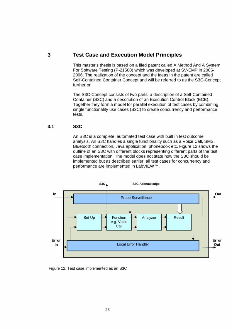
An S3C is a complete, automated test case with built in test outcomeanalysis. An S3C handles a single functionality such as a Voice Call, SMS,Bluetooth connection, Java application, phonebook etc. Figure 12 shows theoutline of an S3C with different blocks representing different parts of the testcase implementation. The model does not state how the S3C should beimplemented but as described earlier, all test cases for concurrency andperformance are implemented in LabVIEW™.
Figure 12. Test case implemented as an S3C
Probe Surveillance
Local Error Handler
Set Up Functione.g. Voice
Call
Analyzer Result
In
ErrorIn
ErrorOut
Out
S3CTrigger
S3C Acknowledge
24
The different blocks of the S3C are:
Probe Surveillance Block. The probe surveillance block is connected to anumber of probes in the platform software and receives information aboutwhat is happening in the platform during test execution. Different test casescan monitor different probes depending on what information they need to fortheir test verdict. The collected information is typically information about thesurrounding environment such as the network, memory usage etc.
Set Up Block. Contains all the relevant initializations and set-ups to beperformed before the function is executed.
Function Block. Contains the use case instructions which make up thefunction. The block also handles triggers and acknowledge signals that areused for synchronization between different S3Cs. Measurements that aredirectly connected to the tested function are also collected here and are eitheranalyzed directly in the function block, or transferred to the analyzer block forprocessing.
Analyzer Block. Handles the post processing for measurements performedduring the execution of the function block such as audio qualitymeasurements or video/audio synchronization.
Result Block. Combines the information from the Analyzer block with theinformation from the Probe Surveillance block to determine whether the testcase passed or failed.
Local Error Handler Block. Handles internal errors in the container likeunexpected behavior of the test object.
3.2 ECB
The ECB (Execution Control Block) is a dispatcher that controls the executionof the different S3Cs. The main idea with the ECB is to raise the level ofabstraction of the test case generation by implementing model based testing.The ECB makes the creation of concurrency and performance test cases adynamic real time event. The S3Cs can either be scheduled into a test suiteand be executed one by one like stand alone function test cases, or they canbe executed in parallel to build up a concurrency test case. Another option isto run the same execution pattern many times or for a very long time to createa performance test case.
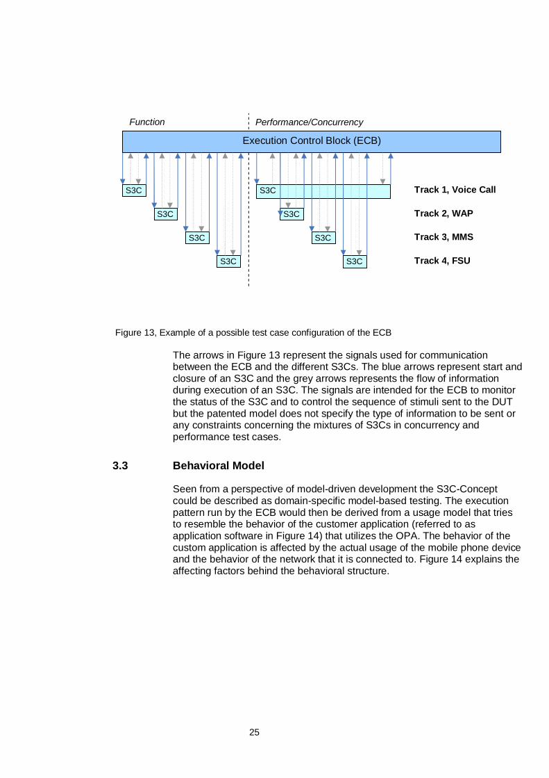
Figure 13 describes two different test runs; a function test and a performanceor concurrency test. The function test is when the S3Cs are executed in aseries without any overlap or parallel execution. The performance orconcurrency test is when two or more S3Cs are executed in parallel whichtests the concurrent ability of the platform. The execution pattern of S3Cs inthe ECB can take almost any shape in terms of duration and number ofparallel tracks so the illustration here is just one way construct a test case.
25
Figure 13, Example of a possible test case configuration of the ECB
The arrows in Figure 13 represent the signals used for communicationbetween the ECB and the different S3Cs. The blue arrows represent start andclosure of an S3C and the grey arrows represents the flow of informationduring execution of an S3C. The signals are intended for the ECB to monitorthe status of the S3C and to control the sequence of stimuli sent to the DUTbut the patented model does not specify the type of information to be sent orany constraints concerning the mixtures of S3Cs in concurrency andperformance test cases.
3.3 Behavioral Model
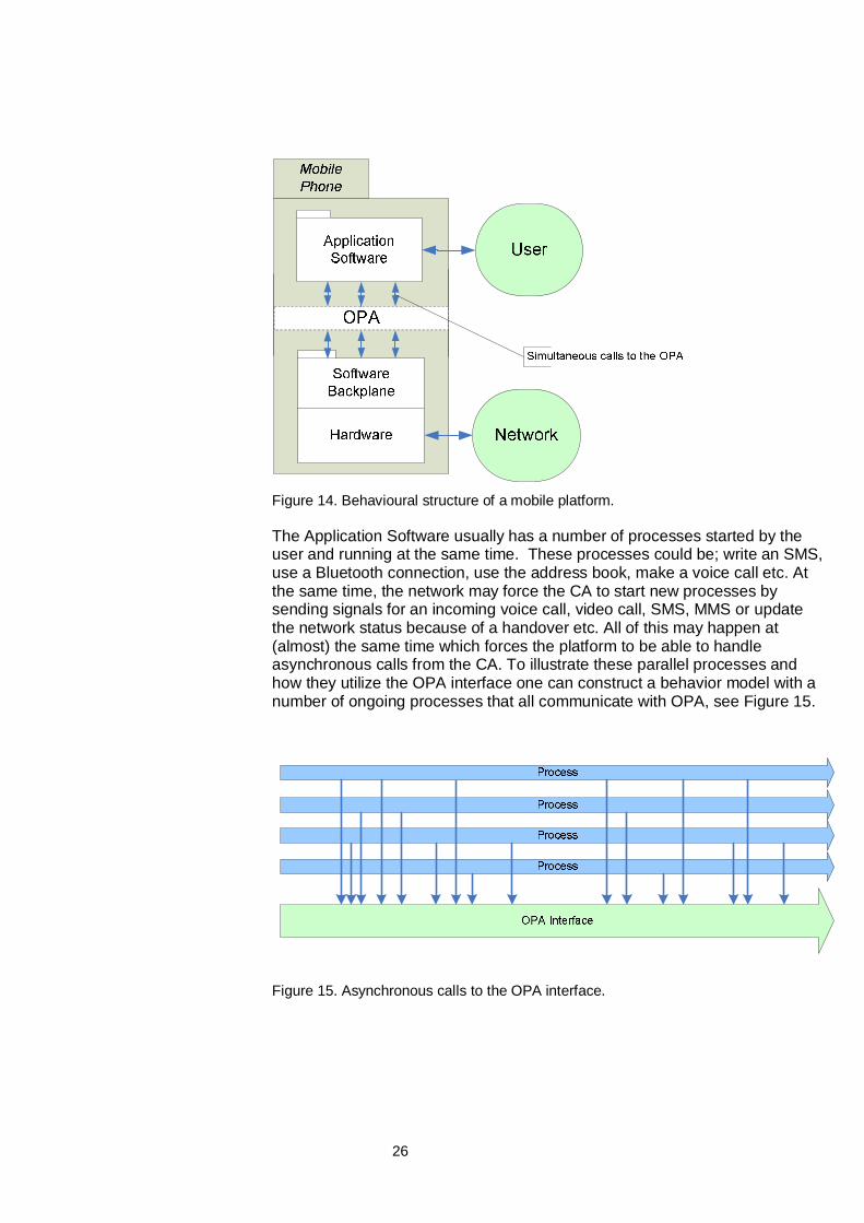
Seen from a perspective of model-driven development the S3C-Conceptcould be described as domain-specific model-based testing. The executionpattern run by the ECB would then be derived from a usage model that triesto resemble the behavior of the customer application (referred to asapplication software in Figure 14) that utilizes the OPA. The behavior of thecustom application is affected by the actual usage of the mobile phone deviceand the behavior of the network that it is connected to. Figure 14 explains theaffecting factors behind the behavioral structure.
Execution Control Block (ECB)
Function Performance/Concurrency
S3C
S3C
S3C
S3C
S3C
S3C
S3C
S3C
Track 1, Voice Call
Track 2, WAP
Track 3, MMS
Track 4, FSU
26
Figure 14. Behavioural structure of a mobile platform.
The Application Software usually has a number of processes started by theuser and running at the same time. These processes could be; write an SMS,use a Bluetooth connection, use the address book, make a voice call etc. Atthe same time, the network may force the CA to start new processes bysending signals for an incoming voice call, video call, SMS, MMS or updatethe network status because of a handover etc. All of this may happen at(almost) the same time which forces the platform to be able to handleasynchronous calls from the CA. To illustrate these parallel processes andhow they utilize the OPA interface one can construct a behavior model with anumber of ongoing processes that all communicate with OPA, see Figure 15.
Figure 15. Asynchronous calls to the OPA interface.
27
The behavioral model is a high abstraction of the platform by encapsulation ofthe asynchronous OPA interface that represents the SUT. It is quite similar tothe idea with an ECB that starts and monitors individual S3Cs which aremade to resemble processes run by a customer application. If two or moreS3Cs run at the same time there is a possibility that the test system will testthe platform in a similar way as it is used by a customer application runningmultiple processes. That is the reason for why SV-EMP creates and runsconcurrency test cases, and why it is important to test that multiple processesmay run at the same time without interfering with each other or cause theplatform to crash.
Restrictions may affect which processes that can be executed in parallel. Bothmultiple identical processes and combinations of unique processes can beimpossible to run in this model, because of limitations in the platform and inthe customer application. The restrictions can either be caused by thehardware and network, or by logical restrictions in the customer application.Hardware and network restrictions may for example be a limitation that onlyone voice call, file transfer, Bluetooth session etc can be conducted at thesame time. This means that S3Cs containing this functionality can not be runas multiple identical processes but they should be able to run in parallel withother, different, S3Cs. Customer application restrictions might be that onlyone instance of a Java program can be started or that it is impossible toaccess the internet while running a WAP session.
Even if some concurrency situations never will occur due to limitations in thecustomer application, the platform should be able to handle those since thelimitations are to be set by SV-EMP’s customers and not by the platformsoftware. Hardware and network limitations has to be taken into considerationsince they affect the testing of the platform, but in general the platform shouldbe able to handle more concurrency situations than what is likely to occur in amobile phone.
28
4 Model and Prototype Development
This section describes the S3C/ECB-Prototype, a collection of softwarecomponents developed during the thesis project in order to investigate andevaluate the S3C-Concept test model described in chapter 3.
The main purpose of the S3C/ECB-Protoype is executing a set of differentLabVIEW programs based on the S3C-Concept called S3C-Scripts, executinga set of S3C-Scripts is called performing a S3C/ECB-Test .
4.1 The different parts of the S3C/ECB-Prototype
The S3C/ECB prototype is built up of these four main parts:
• The S3C-Scripts. Components developed and run in LabVIEW™. Theirdesign is based on the S3C-Concept and the principles described inchapter 3.1. These test scripts are not to be confused with basic textscripts, they comprise of all functions needed to independently from eachother, perform a test of a specific function on a DUT.
• Test Execution Scripts. User written command-scripts native to theS3C/ECB-Prototype. These are used for defining how and when S3C-Scripts will be executed.
• The ECB-Tool. An application that controls S3C-Scripts execution, it isdeveloped according to the ECB model in the S3C-Concept. Its main useis executing Test Execution Scripts.
• S3CRunServer. A LabVIEW server used for initiating and starting theS3C-Scripts.
29
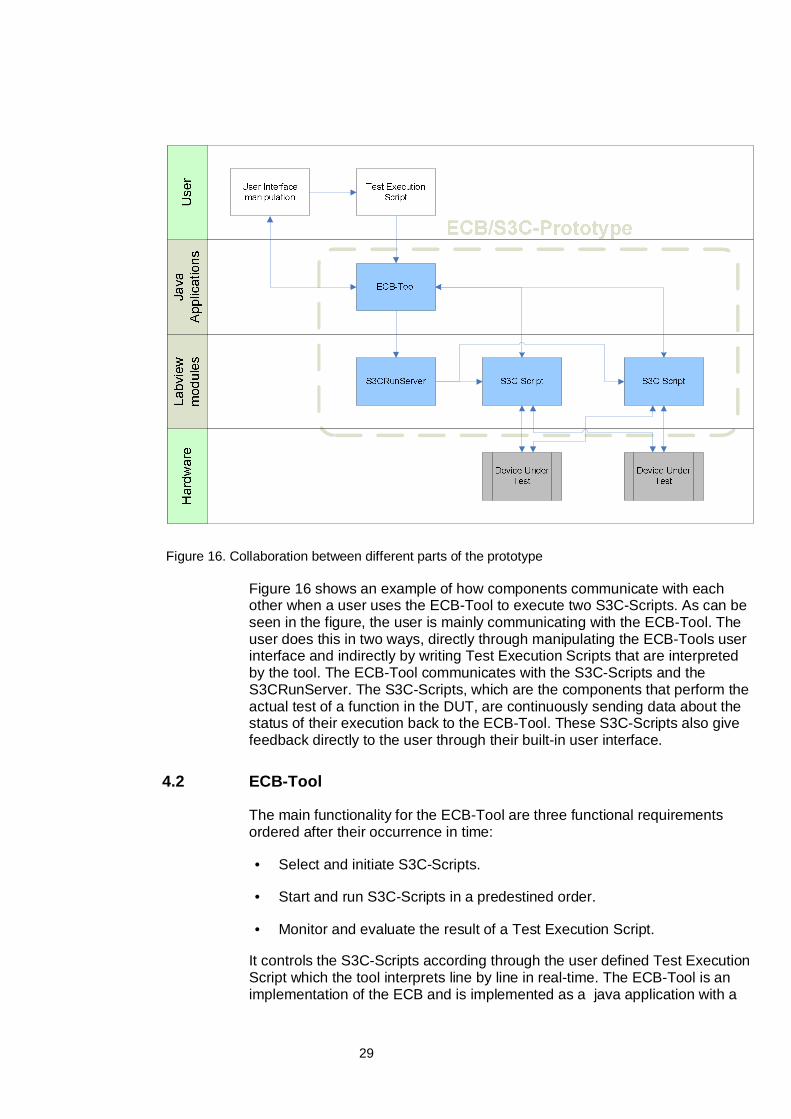
Figure 16. Collaboration between different parts of the prototype
Figure 16 shows an example of how components communicate with eachother when a user uses the ECB-Tool to execute two S3C-Scripts. As can beseen in the figure, the user is mainly communicating with the ECB-Tool. Theuser does this in two ways, directly through manipulating the ECB-Tools userinterface and indirectly by writing Test Execution Scripts that are interpretedby the tool. The ECB-Tool communicates with the S3C-Scripts and theS3CRunServer. The S3C-Scripts, which are the components that perform theactual test of a function in the DUT, are continuously sending data about thestatus of their execution back to the ECB-Tool. These S3C-Scripts also givefeedback directly to the user through their built-in user interface.
4.2 ECB-Tool
The main functionality for the ECB-Tool are three functional requirementsordered after their occurrence in time:
• Select and initiate S3C-Scripts.
• Start and run S3C-Scripts in a predestined order.
• Monitor and evaluate the result of a Test Execution Script.
It controls the S3C-Scripts according through the user defined Test ExecutionScript which the tool interprets line by line in real-time. The ECB-Tool is animplementation of the ECB and is implemented as a java application with a
30
GUI and functionality to communicate with the S3C-Scripts via TCP/IPconnections.
4.2.1 Understanding the ECB-Tool
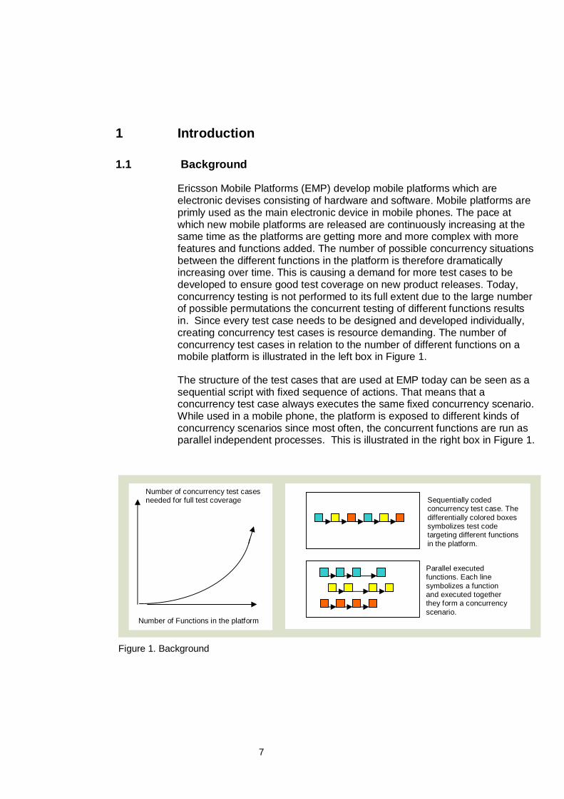
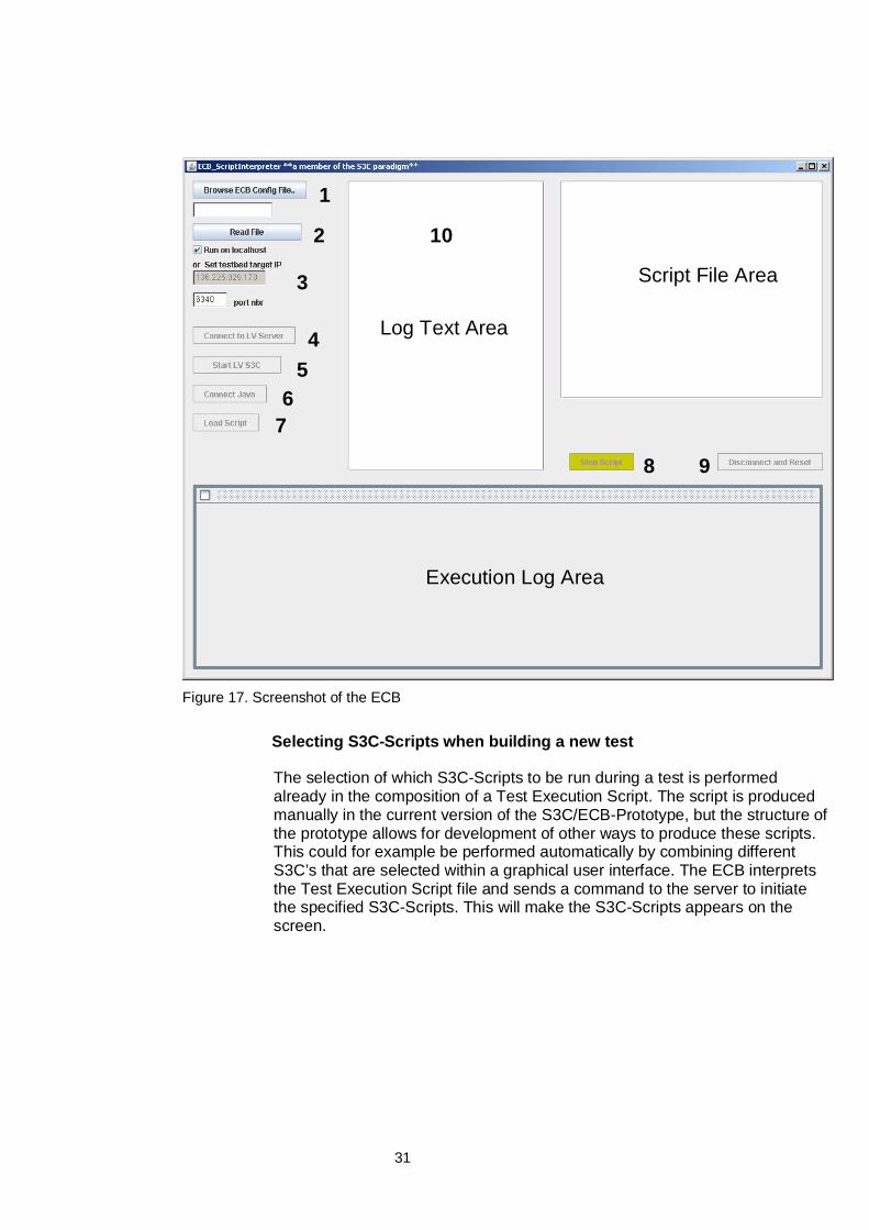
A screenshot of the ECB is shown in Figure 17. Different parts and functionsin the GUI are:
1 A Test Execution Script-file is selected from a file selector by clicking the“Browse ECB Config File” button.
2 The file is read, displayed in the upper right text area and its content isstored in the application memory by clicking the “Read File” button.
3 Settings for IP-number and port for the server in LabVIEW™ that initiatesthe S3C-Scripts. Default is localhost.
4 The “Connect to LV Server” button connects the ECB-Tool application viaTCP/IP connection to the S3C-Scripts built-in TCP/IP-server, theseservers naturally has to be up and running while this action takes place.
5 The “Start LV S3C” buttons makes the ECB-Tool send commands to openthe S3C-Scripts main method (in LabVIEW™ these are called Top Vis)and to send parameters for test duration and a TCP/IP port number to beused later for communication. At the same time the ECB initiates internaljava objects that handles S3C-Script communication.
6 The “Connect Java” button connects the ECB-Tool to the S3C-Scripts. Itstarts the status measuring by starting one progress bar for every S3C inthe bottom frame. From this point the ECB-Tool measures and displaysthe status for the connected S3C-Scripts.
7 The “Load Script” button reads the execution part of the script and storesthem in a list.
8 The “Step Script” button executes one line from the script by reading it ina script interpreter and makes the ECB-Tool perform the required actionsuch as sending “start_tc” to one of the S3C-Scripts to make it start itsexecution.
9 The “Disconnect and Reset” button disconnects the ECB-Tool from theserver and all communication with the S3C-Scripts are shut down.
10 Log window used for displaying information to the user.
31
Figure 17. Screenshot of the ECB
Selecting S3C-Scripts when building a new test
The selection of which S3C-Scripts to be run during a test is performedalready in the composition of a Test Execution Script. The script is producedmanually in the current version of the S3C/ECB-Prototype, but the structure ofthe prototype allows for development of other ways to produce these scripts.This could for example be performed automatically by combining differentS3C’s that are selected within a graphical user interface. The ECB interpretsthe Test Execution Script file and sends a command to the server to initiatethe specified S3C-Scripts. This will make the S3C-Scripts appears on thescreen.
1
2 10
3
45
6 7
8 9
Execution Log Area
Script File Area
Log Text Area
32
Running a S3C/ECB-Test consisting of a collection of S3C-Scripts in apredetermined order
After the S3C-Scripts have been selected and initiated by the server, theECB-Tool opens a TCP/IP connection to the S3C-Scripts which is used forsending commands to start the test case and receive information of theprogress of the S3C-Scripts. When the connections are established allconnected S3C-Scripts are in their initial state. The monitoring in theexecution log area is started. The ECB sends the commands in the script fileby having the person executing the test clicking the “Step Script” button in theECB GUI which reads the next line in the script and performs actionsaccording to the content of the script line. When all the S3C-Scripts arestarted, the only task left to perform is to monitor the result of the testexecution.
Monitor and evaluate a S3C/ECB-test
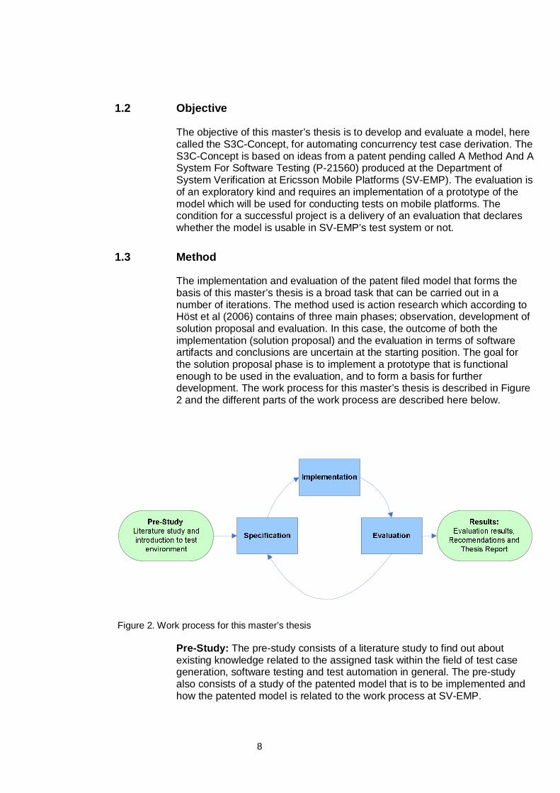
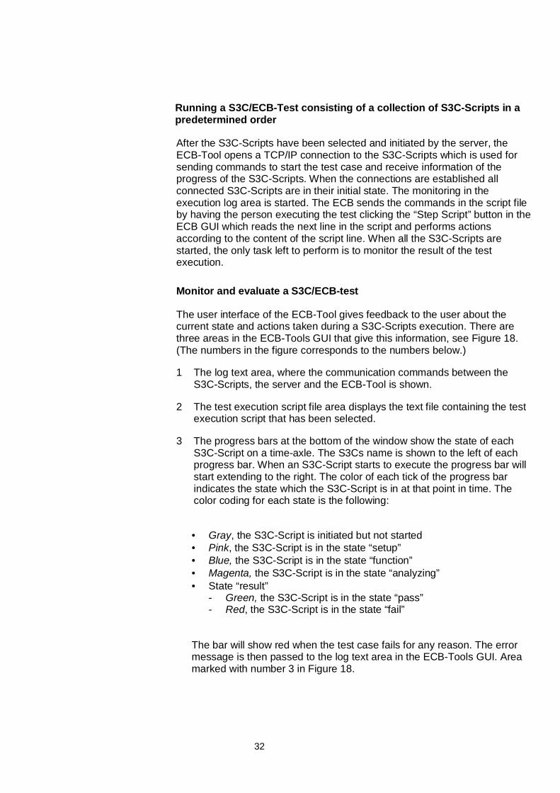
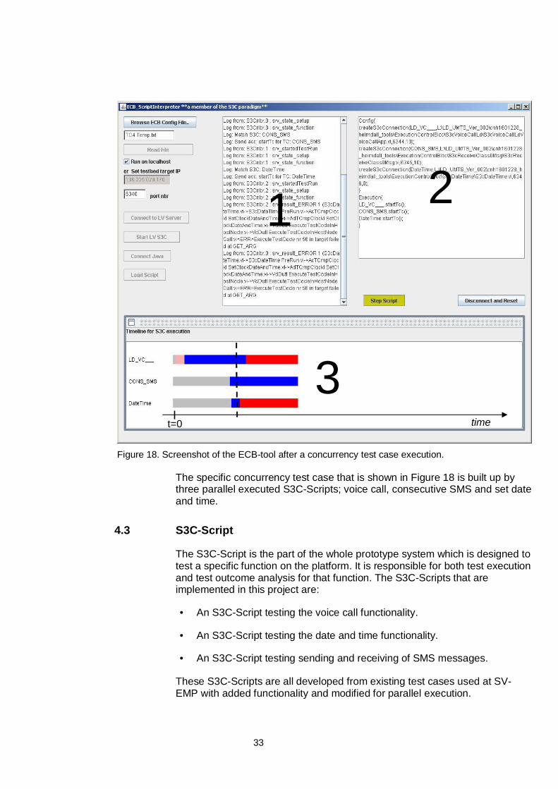
The user interface of the ECB-Tool gives feedback to the user about thecurrent state and actions taken during a S3C-Scripts execution. There arethree areas in the ECB-Tools GUI that give this information, see Figure 18.(The numbers in the figure corresponds to the numbers below.)
1 The log text area, where the communication commands between theS3C-Scripts, the server and the ECB-Tool is shown.
2 The test execution script file area displays the text file containing the testexecution script that has been selected.
3 The progress bars at the bottom of the window show the state of eachS3C-Script on a time-axle. The S3Cs name is shown to the left of eachprogress bar. When an S3C-Script starts to execute the progress bar willstart extending to the right. The color of each tick of the progress barindicates the state which the S3C-Script is in at that point in time. Thecolor coding for each state is the following:
• Gray, the S3C-Script is initiated but not started• Pink, the S3C-Script is in the state “setup”• Blue, the S3C-Script is in the state “function”• Magenta, the S3C-Script is in the state “analyzing”• State “result”
- Green, the S3C-Script is in the state “pass”- Red, the S3C-Script is in the state “fail”
The bar will show red when the test case fails for any reason. The errormessage is then passed to the log text area in the ECB-Tools GUI. Areamarked with number 3 in Figure 18.
33
Figure 18. Screenshot of the ECB-tool after a concurrency test case execution.
The specific concurrency test case that is shown in Figure 18 is built up bythree parallel executed S3C-Scripts; voice call, consecutive SMS and set dateand time.
4.3 S3C-Script
The S3C-Script is the part of the whole prototype system which is designed totest a specific function on the platform. It is responsible for both test executionand test outcome analysis for that function. The S3C-Scripts that areimplemented in this project are:
• An S3C-Script testing the voice call functionality.
• An S3C-Script testing the date and time functionality.
• An S3C-Script testing sending and receiving of SMS messages.
These S3C-Scripts are all developed from existing test cases used at SV-EMP with added functionality and modified for parallel execution.
1 2
3t=0 time
34
4.3.1 General build up of an S3C-Script.
An S3C-Script is designed to work through four different phases or states(Setup, Function, Analyzer, Result, see 3.1) to perform its task. It also has astate when it is initiated but not started and it is in that state that theconnection with the ECB is established. These states are the same for allS3Cs.
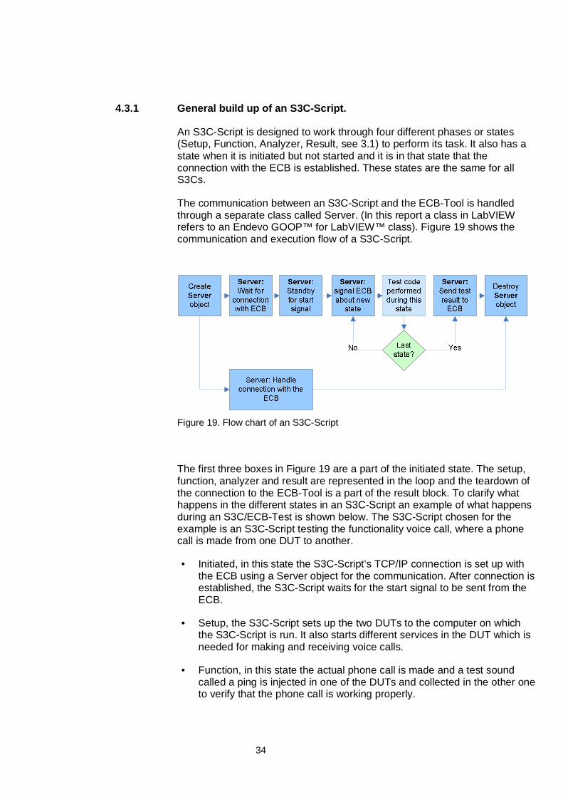
The communication between an S3C-Script and the ECB-Tool is handledthrough a separate class called Server. (In this report a class in LabVIEWrefers to an Endevo GOOP™ for LabVIEW™ class). Figure 19 shows thecommunication and execution flow of a S3C-Script.
Figure 19. Flow chart of an S3C-Script
The first three boxes in Figure 19 are a part of the initiated state. The setup,function, analyzer and result are represented in the loop and the teardown ofthe connection to the ECB-Tool is a part of the result block. To clarify whathappens in the different states in an S3C-Script an example of what happensduring an S3C/ECB-Test is shown below. The S3C-Script chosen for theexample is an S3C-Script testing the functionality voice call, where a phonecall is made from one DUT to another.
• Initiated, in this state the S3C-Script’s TCP/IP connection is set up withthe ECB using a Server object for the communication. After connection isestablished, the S3C-Script waits for the start signal to be sent from theECB.
• Setup, the S3C-Script sets up the two DUTs to the computer on whichthe S3C-Script is run. It also starts different services in the DUT which isneeded for making and receiving voice calls.
• Function, in this state the actual phone call is made and a test soundcalled a ping is injected in one of the DUTs and collected in the other oneto verify that the phone call is working properly.
35
• Analyzing, is when the data recorded in the function is processed andanalyzed to determine if the function performed correctly. In the case ofthe voice call, the verifying is mainly performed in the function state, butthe final test outcome analysis is performed in this state.
• Result, this is when the result of the test performed by the S3C-Script issent to the ECB-Tool and immediately after the S3C-Script goes intoeither the state pass or the state fail, depending on what the result is setto in the analyzer state.
If at any time an error occurs during the S3C-Script’s execution, the executionis aborted, the S3C-Script goes into the state fail, and an error message issent to the ECB-Tool.
4.3.2 Parameters and settings
When the S3C-Script is initiated, parameters from the script file can be set inthe S3C-Script in order to control the duration, communication and execution.The parameter that is passed in the initiation in this implementation is areference to an object which holds the connection to the DUT’s. Therefore ithas to be shared between the S3C-Scripts in the test case. This solutionworks even if some S3C-Scripts only interact with one of the connectedDUTs.
The settings that are passed in the initiation are the port number on which toconnect to the ECB application and the duration of the S3C-Script in thosecases that there is a possibility to set the duration. There are three main typesof test cases in terms of duration:
• Single event test cases, unable or unsuitable too loop which thereforeare unable to vary their duration.
• Single event test cases which can be looped in order to perform thesame task many times in a row such as sending an SMS and thereforecan vary their duration.
• Continuous test cases that start a continuous process in the DUT suchas a voice call that can vary in duration.
36
The duration settings can be used to create performance test cases of S3C-Scripts that typically execute for a long time or with many iterations in order toinvestigate repetitive performance and discover memory leaks. The durationcan also be used in order to prolong short S3Cs in order to increase theamount of time for concurrent processes to execute in parallel. The possibilityto send in different references and parameters at initiation also enables theECB-Tool to prepare and adjust the S3C-Scripts for the specific test case thatthe script file describes, before the execution starts. It can thereby avoidunnecessary communication during execution which might interfere with thetest system. The parameters supported in the current implementation areduration, port number and a reference to the shared object that holds thereference to the DUTs.
4.3.3 Synchronization
During the S3C-Scripts development, a need for having exclusive access toboth the DUTs and some of the collective objects in LabVIEW™ arose. In theconcurrency tests used today, the mixing of two function tests into aconcurrency test is done through executing pieces of each function test in apredefined sequence. This means that each function takes turns in executing.The implication of this is that certain subroutines e.g. the subroutinescontrolling the DUT’s OPA, are called in a sequential manner.
37
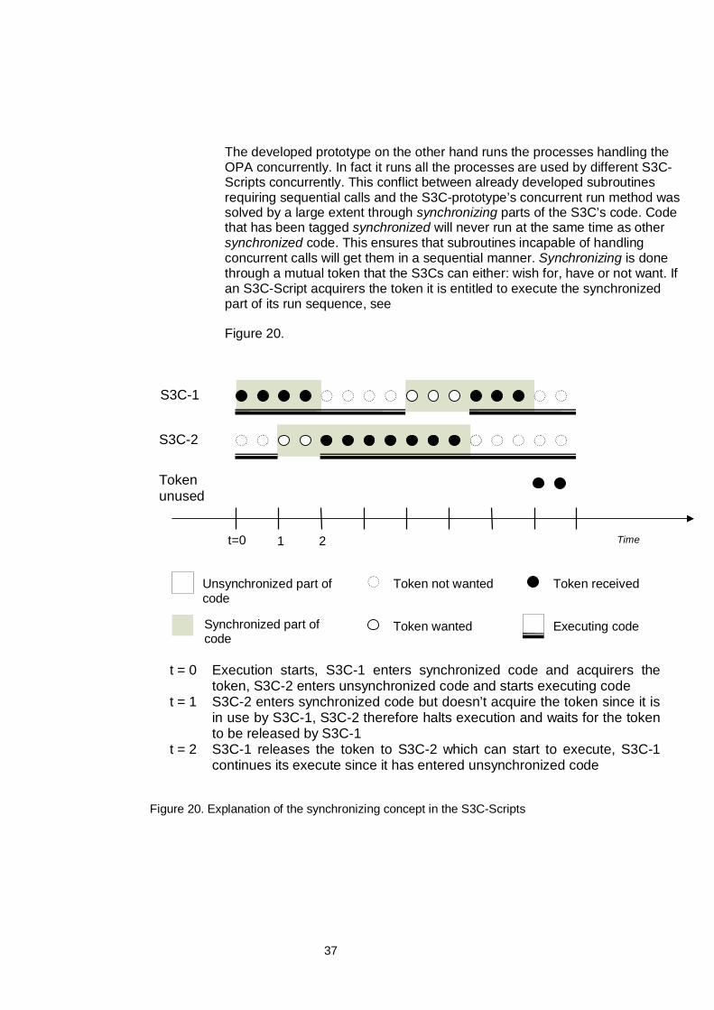
The developed prototype on the other hand runs the processes handling theOPA concurrently. In fact it runs all the processes are used by different S3C-Scripts concurrently. This conflict between already developed subroutinesrequiring sequential calls and the S3C-prototype’s concurrent run method wassolved by a large extent through synchronizing parts of the S3C’s code. Codethat has been tagged synchronized will never run at the same time as othersynchronized code. This ensures that subroutines incapable of handlingconcurrent calls will get them in a sequential manner. Synchronizing is donethrough a mutual token that the S3Cs can either: wish for, have or not want. Ifan S3C-Script acquirers the token it is entitled to execute the synchronizedpart of its run sequence, see
Figure 20.
Figure 20. Explanation of the synchronizing concept in the S3C-Scripts
Time
S3C-2
S3C-1
Unsynchronized part ofcode
Synchronized part ofcode
t=0 1
t = 0 Execution starts, S3C-1 enters synchronized code and acquirers thetoken, S3C-2 enters unsynchronized code and starts executing code
t = 1 S3C-2 enters synchronized code but doesn’t acquire the token since it isin use by S3C-1, S3C-2 therefore halts execution and waits for the tokento be released by S3C-1
t = 2 S3C-1 releases the token to S3C-2 which can start to execute, S3C-1continues its execute since it has entered unsynchronized code
Token not wanted
Token wanted
Token received
Executing code
Tokenunused
2
38
4.4 S3C Connection Server
The S3C Connection Server is used by the ECB-Tool to start up differentS3C-Scripts. It also starts up the needed processes that enable S3C-Scriptsto interact with the DUTs connected to the test bed computer. The server isrunning continuously, waiting for the ECB-Tool to connect. When the ECB-Tool has connected to the connection server it can order the server to start updifferent S3C-Scripts by sending a request to the server containing the filepath and other information from the script file such as parameters and settingthat the S3C-Scripts need in order to be initiated.
4.5 The Test Execution Script
The script file consists of a set of commands to be read and executed by theECB-Tool. It is the script that describes the use case upon which the test caseis based. Therefore is the creation of the script an important task that is to beperformed according to the test specifications developed in phase one in theSV-EMP System Verification work process, see 2.3.4. Test specificationsmight also imply creation of new S3C-Scripts if new functionality is added inthe platform release or if existing functionality needs new testing methods. Inthe current implementation the scripts main functionality is to state whichS3C-Scripts should be included in the test case and in what order they shouldbe executed. Further development of both the scripting syntax and strategiesfor producing scripts is needed in order to make this part of the modelimplementation more efficient, see 6.2 for ideas of how do develop the scriptfile. Documentation of the syntax for a script can be found in the Appendix:Using the S3C/ECB Prototype.
4.6 Aspects affecting the technical solution
In order to determine the quality of the test system and the test cases itproduces it is important to look at both the system as a whole and at theindividual pieces that constitutes a test case. Assuming that the solution withone ECB-Tool to start and run several S3C-Scripts is the design chosen toimplement model based testing, there are still questions of whether to put theintelligent control of the execution in the script run by the ECB, or the if theS3C-Scripts should be as self contained and intelligent as possible.
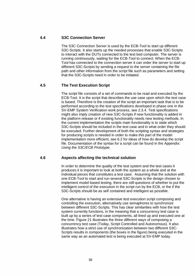
One alternative is having an extensive test execution script composing andcontrolling the execution, alternatively use semaphores to synchronizebetween different S3C-Scripts. This has clear similarities with how the testsystem currently functions, in the meaning that a concurrency test case isbuilt up by a series of test case components, all lined up and executed one atthe time. Figure 21 illustrates the three different ways of composing aconcurrency test case (Today, Script Controlled and Autonomous). It alsoillustrates how a strict use of synchronization between two different S3C-Scripts results in components (the boxes in the figure) being executed in thesame way as an automated test is being executed at SV-EMP today.
39
Figure 21, Execution patterns
Report result
The different states of a test case are symbolizedby boxes in different colours. Every state containsone or more test case components depending onfor example how extensive a setup is and howmuch is done in the function part of the test case.In the following example the different test casescomponents are numbered with 1 and 2.
TodayThe components are lined up in a row andexecuted in a series
1 2 1 2 1 2 1 2 1 2 1 2
Script Controlled ExecutionThe components are executed in the same order as today but theyare contained in different S3Cs
Time
1
2
1
2
1
2
1
2
1
2
1
2Time
Parallel Execution (Autonomous)The S3Cs and its components are executed in parallel with noscript control during execution.
1
2
1
2
1
2
1
2
1
2
1
2Time
Analyzer
Function
SetUp
40
The main difference between the solution with script controlled execution andthe currently used concurrency test cases would be that the components areplaced in different containers. Having different containers means that thesoftware artifacts can be re-used and combined with other functionalitywithout having to change any code. There would only be a need to write newS3C-Scripts containing the new combinations.
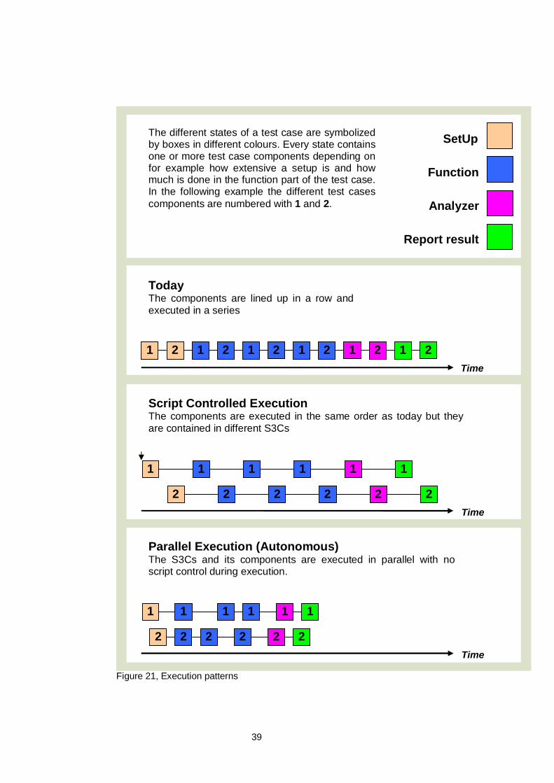
Figure 22 illustrates how the two different ways of designing S3Cs shown inFigure 21 (Scrip Controlled and Autonomous) affects the communicationbetween the S3Cs and the ECB. Scenario one represents a moreautonomous approach to constructing S3C-Scripts which is similar to theparallel execution pattern. The other scenario represents an S3C constructedaccording to the Script Control execution pattern.
Figure 22, Autonomous or Script dependent S3Cs.
Scenario 1, Autonomous S3Cs
Time
Start signal is sent to the S3C
Function AnalyzerS3C
State changes is reported to the ECBbut the execution of the S3Ccontinues unaffected by thesurrounding environment
The result from the test of thefunctionality of the individual S3C isreported as either pass or fail and theS3C shuts down.
SetUp
Time
SetUp FunctionS3C
Start signal and configurationinformation about the other S3C’sare sent and the S3C then have toadapt to fit in the test suite.
The start of each new state iscontrolled by the ECB to firmly controlthe composition of the test case.These types of control can also beplaced inside the blocks and pausesin the execution can be made.
PauseAnalyzer
The pass or fail of this S3C might bedependent on the result of otherS3C’s progress if they are closelyintegrated.
Scenario 2, Script Controlled S3Cs
41
5 Evaluation and Discussion
The main question that the evaluation of the S3C-Concept tries to answer iswhether it will be a good solution to adopt model based testing and constructdynamic concurrency and performance test cases using the proposed model,or if it is better to continue with the test case development that is used at SV-EMP today. The evaluation also aims to determine what technical solution willbe the best for SV-EMP to use for the implementation of the model basedtesting and how this defines the ECB-Tool and the construction of the S3C-Scripts.
The different technical solutions presented in show that there has to be adecision of how autonomous the S3C-Scripts should be in order to achievegood performance by the test system. The technical solution described inchapter 4 is an implementation of the parallel execution model illustrated inFigure 21 with some synchronization added to the analyzer state (thissynchronization makes the execution possible using the current test system atEMP). During the function state of the three developed S3C-Scripts areexecuted in parallel without any synchronization. The knowledge gained fromthat implementation together with inspections of existing test cases makes itpossible to perform the evaluation and draw conclusions of the abilities of thedifferent solutions. As mentioned in chapter 1.3 there are five differentaspects considered in the evaluation:
• Stability of the test system
• Traceability for errors
• Enabling of creation of specific test scenarios
• Number of specific S3C-Scripts (Code re-use)
• Fault finding capability and Test Coverage
5.1.1 Stability of the test system
Stability in the test system is measured in terms of the amount of errorsoccurring in the test system due to failure in the functionality of the testsystem. (These errors are no to be confused with test case failures, which arecaused due to the DUTs not working according to specification.)
Stability in the test system is very important in order to make the testingeffective because every test that fails has to be analyzed manually by a testdeveloper that investigates whether it was the test case that failed or theplatform that produced an error. This operation takes up a various amount oftime from ten minutes up to a few hours per IR for complicated problems andwith more than one thousand test cases per regression test-run, an instabletest system could compromise the delivery dates and might eventually delaythe delivery of new platform releases.
42
Test case failures in a test system with parallel executions can have threemajor causes:
• External causes such as problems with the test bed equipment andnetwork related incidents that occur during execution of the test case.
• Internal failures in one S3C-Script which is equivalent to the test casefailures that are the most common today due to problems with test casecomponents or measuring activities.
• Interference between different S3C-Scripts due to race conditions formutual recourses and interfering measurement activities in different S3C-Scripts.
The first two causes of failure remain almost the same in terms of occurrenceindependently of whether concurrency test cases consists of parallel executedS3C-Scripts or if they are coded as in sequence as today. However, theamount of test case code to produce and maintain is likely to decrease if S3C-concept is adopted. With equivalent personnel resources the implementationof the S3C-Concept probably will lead to higher quality test scripts beingdeveloped since the developers can spend more time on a less amount ofcode due to the S3C-Concept leading to more re-use of code
The third cause of test case failures is introduced by the parallel execution ofS3C-Scripts and has major implications on the stability of the test systemused today at SV-EMP. It is likely that a lot of the code used in today’s testsystem needs to be rewritten to prevent interference between different S3C-Scripts. It is resource consuming to reconstruct the whole test system and anextensive analysis needs to be made at how much resources would beneeded to implement such a change. But it might be a necessary action inorder to save resources further on in the development and maintenance of thesystem and to avoid problems with mutual resources and interferingmeasuring processes.
Reconstruction of the whole system means reengineering of manyLabVIEW™ components (In LabVIEW™ this specifically means changing theVIs in the Visual Driver; AD, AC layers in order to enable code re-usebetween S3C-Scripts, but preparing the VIs in the lower layers so that they donot interfere with each other if executed in parallel).
One possible way to limit the extent of the test system that needs to bereworked for the enabling of parallel execution, is to utilize thesynchronization of S3C-Scripts that was proposed in 4.3.3. Synchronizingover parts of the S3C-Scripts will limit the amount of the test platform that willneed to be able to handle concurrent S3C-Scripts. For a limited amount ofconcurrency testing synchronizing might be a god solution but if the S3C-Concept is chosen to be implemented for all concurrency tests being used atSV-EMP the department would probably benefit from a total redesign of thewhole test system including the lower layers, but this needs to be furtheranalyzed.
43
5.1.2 Traceability for errors
Traceability for errors is measured in terms of the ability to find the source ofan error and the possibility to recreate the chain of events that caused theerror. A good traceability for errors simplifies the handling of IRs regardless ofif it is a test case error or a platform error and is therefore important for theoverall test system performance.
In the current test system errors are passed in a chain of links through all themethods being executed in an automated test. This means that in thecurrently used automated tests the error can be traced through the executionsequence back to the method where the error originated. The same way oflinking error signals in the way of a chain is used in the S3C-Scripts. Theproblem is that if two or more S3C-Scripts are executed in parallel there willbe multiple chains of linked error signals working in the LabVIEW™environment at the same time. This sometimes leads to errors beingtransferred between different S3C-Scripts. So even if the source of the error isknown the causes might be difficult to analyze since an error that occurred inone S3C-Script could have been inadvertently transmitted to another S3C-Script.
Another aspect of traceability for errors is that a re-run of a test executed inthe ECB-Tool does not guarantee that events are executed at exactly thesame time every time. An exact copy of a previously run ECB/S3C-Test caseis in fact very unlikely both the execution path and the timing between OPAcalls are considered. This is due to factors such as CPU load, thread handlingby the operation system of the test bed or other environment circumstancesthat affects speed and timing of when individual S3C-Scripts are executed. Ifthe test execution would be strictly controlled by the script as in Figure 22,scenario 2, the error tracing is simplified and almost equal to how it isperformed at SV-EMP today. The only tracing problem would then be tocontrol the exact timing between OPA calls, but that is not controllable eventoday so the need for very exactly timed sequences is probably limited.
A possible solution to traceability problems caused by autonomous S3C-Scripts is to keep track of what stimuli have been sent to the DUT. Anothersolution is to utilize other logs that can reveal in what state or transition allrunning S3C-Scripts were at the moment where one of the executing S3C-Scripts failed and generated an error code.
5.1.3 Enabling creation of specific test scenarios
If the traceability depends on how autonomous the S3C-Scripts are, thepossibility of creating test scenarios depends on how controllable the S3C-Scripts are in aspects of time and content. If the S3C-Scripts are tooindependent it will be difficult to create a specific and fully controlled test casewith the ECB. Today, the test developer is free to create any scenario andmeasurement in the test cases. If the test developers get information from theplatform developers concerning areas that need more testing, it is up to thetester to develop test cases for scenarios that investigates these areassuspected to be sensitive for concurrency situations.
44
The approach with parallel execution is somewhat different in the sense that itmight be difficult to control the exact sequence of stimuli to the OPA andmeasurements being done on the DUT. But instead there is the possibility toautomatically create as many ECB tests needed, with the same functionalitybut with different timing to try to test the concurrency situation properly. This isdone by running the same ECB test many times and starting the differentS3C-Scripts at different times to investigate whether the suspectedconcurrency problem occurs during any of the test executions.
In order to enable the creation of specific test scenarios and more controlledexecution the use of a more script controlled S3C-Scripts is to be prefered,refer to scenario 2 in Figure 22. An alternative could be to have S3C-Scriptswhere the test developer via the script could activate and deactivate scriptcontrolled pauses and semaphores where needed using a blend of scenario 1and scenario 2 in the same figure.
5.1.4 Number of specific S3C-Scripts (Code re-use)
The way of constructing concurrency test cases by parallel execution of S3C-Scripts opens up for a possibility to re-use the test code from single-functionality test cases in concurrency test cases. The different test cases(function, concurrency and performance) then have to have individual S3C-Scripts in order to be started but a Test Execution Script consist of a far lessamount of code than a new test case. This fact is central in the argumentationfor a test system with parallel executed S3C-Scripts.
The consideration about whether to place intelligence in the S3C-Scriptsthemselves or in the Test Execution Script run by the ECB-Tool, affects thedevelopment of test cases and the amount of code that needs to beproduced. A solution with autonomous S3C-Scripts is likely to imply less codegenerated in total and a less amount of S3C-Scripts needed to be createdand maintained in the test system. A solution with less intelligent S3Cs thatneed to be more controlled during execution by the Test Execution Scriptwould require much more resources in for the Test Execution Scriptdevelopment.
The need for very timing-dependent test scenarios that require script controlS3C-Scripts has to be weighted against the aim for increased code re-use.One solution to keep some strictly timing-dependent test scenarios is offcause to have different solutions for different types off test cases and allowdevelopment of sequential test cases to test specific scenarios.
45
5.1.5 Fault finding capability and test coverage
Since both the test execution and test validation is incorporated in the S3C-Scripts, the quality of the test case in terms of fault finding capability isdependent on the quality of the measurement that monitors that the platformresponds to stimuli. If several S3C-Scripts are executing at the time there is arisk that for example measurement on an audio channel is interfered by manydifferent S3C-Scripts that needing to use the audio channel for verifying theirtest. This problem can be solved by incorporating more advanced analyzingabilities into the S3C-Scripts so that they can decide whether the unexpectedinterference on the audio channel was due to an interfering process using thesame mutual resource or a platform failure.
This implies a need for communication between the S3C-Scripts orcommunication with a separate measurement process that monitors allmeasurement data. This external process should run in parallel with all theS3C-Scripts during a whole ECB test and communicate to the S3C-Scriptswhen the S3C-Scripts validation process needs to take in account thatanother S3C is using the same measurement resource. In the example of theaudio channel the external measurement process could signal the S3Cmeasuring the audio channel that another S3C is currently putting in sound onthe audio channel and what the altered validation criteria for the first S3C-Script should be.
One of the major advantages of a test system using the S3C-Concept, thatdynamically constructs concurrency test cases, is that the test coverage forconcurrency situations could increase dramatically with the same amount oftest development resources as today. Both in the coverage of possibleexecution paths when using two or more functions at the same time byvarying the start time of the different S3C-Scripts in relation to each other, andin the coverage of the general concurrency scenarios with many differentfunctions utilized at the same time.
However, test coverage measures can be of variable importance since theydo not reveal any exact information about how many of the existing errors thathas been found. Andersson et al (2007) has shown in empirical studies oflarge software development projects that a major amount of the existingerrors are likely to be concentrated to a minor amount of the softwaremodules. This implies that the test coverage is not directly correlated to thepercentage of found faults. A better test coverage may lead to the findings ofmore errors and eventually lead to better software quality of the platform, buthigh test coverage itself is nu guarantee for error free software.
The input to the test design activity described in 2.3.4 thus has to be morethan just test coverage requirements in order to increase the fault findingcapability of the executed test cases. Information such as suspectedtroublesome software components or performance demanding concurrencyscenarios where errors are likely to occur, needs to be included in the designactivity. Such information together with an increased test coverage could forma basis for an over all better performance of the test process at SV-EMP.
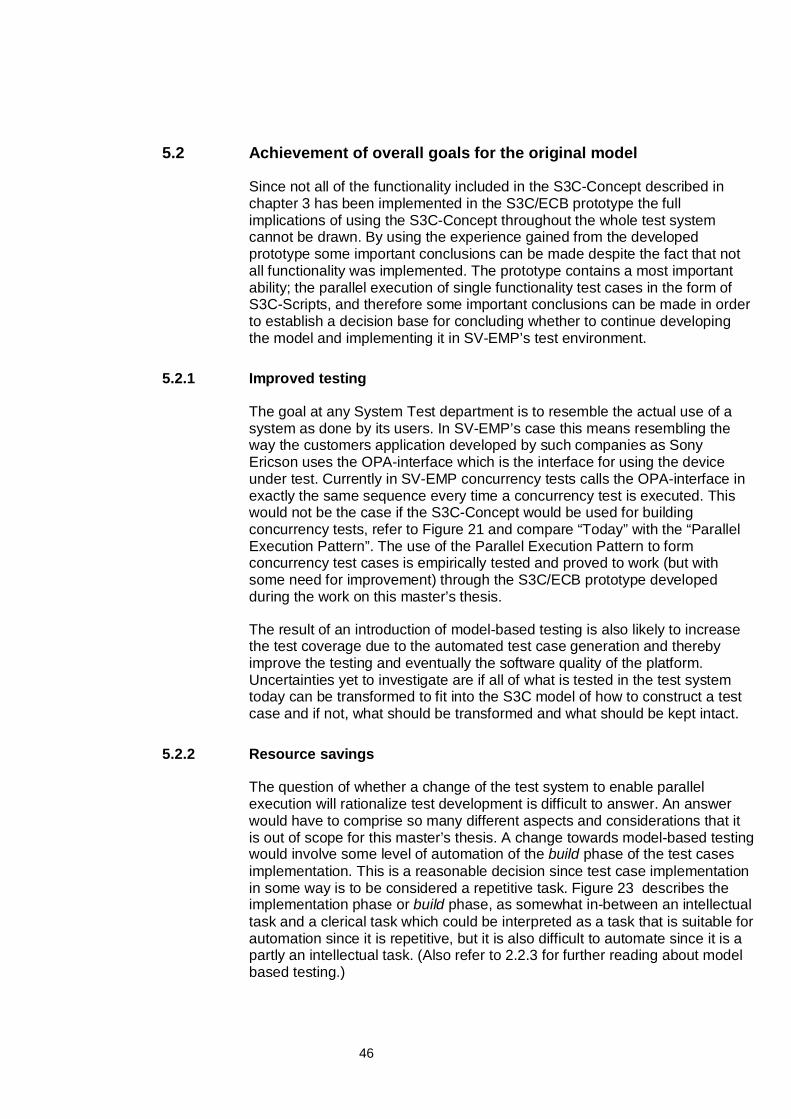
46
5.2 Achievement of overall goals for the original model
Since not all of the functionality included in the S3C-Concept described inchapter 3 has been implemented in the S3C/ECB prototype the fullimplications of using the S3C-Concept throughout the whole test systemcannot be drawn. By using the experience gained from the developedprototype some important conclusions can be made despite the fact that notall functionality was implemented. The prototype contains a most importantability; the parallel execution of single functionality test cases in the form ofS3C-Scripts, and therefore some important conclusions can be made in orderto establish a decision base for concluding whether to continue developingthe model and implementing it in SV-EMP’s test environment.
5.2.1 Improved testing
The goal at any System Test department is to resemble the actual use of asystem as done by its users. In SV-EMP’s case this means resembling theway the customers application developed by such companies as SonyEricson uses the OPA-interface which is the interface for using the deviceunder test. Currently in SV-EMP concurrency tests calls the OPA-interface inexactly the same sequence every time a concurrency test is executed. Thiswould not be the case if the S3C-Concept would be used for buildingconcurrency tests, refer to Figure 21 and compare “Today” with the “ParallelExecution Pattern”. The use of the Parallel Execution Pattern to formconcurrency test cases is empirically tested and proved to work (but withsome need for improvement) through the S3C/ECB prototype developedduring the work on this master’s thesis.
The result of an introduction of model-based testing is also likely to increasethe test coverage due to the automated test case generation and therebyimprove the testing and eventually the software quality of the platform.Uncertainties yet to investigate are if all of what is tested in the test systemtoday can be transformed to fit into the S3C model of how to construct a testcase and if not, what should be transformed and what should be kept intact.
5.2.2 Resource savings
The question of whether a change of the test system to enable parallelexecution will rationalize test development is difficult to answer. An answerwould have to comprise so many different aspects and considerations that itis out of scope for this master’s thesis. A change towards model-based testingwould involve some level of automation of the build phase of the test casesimplementation. This is a reasonable decision since test case implementationin some way is to be considered a repetitive task. Figure 23 describes theimplementation phase or build phase, as somewhat in-between an intellectualtask and a clerical task which could be interpreted as a task that is suitable forautomation since it is repetitive, but it is also difficult to automate since it is apartly an intellectual task. (Also refer to 2.2.3 for further reading about modelbased testing.)
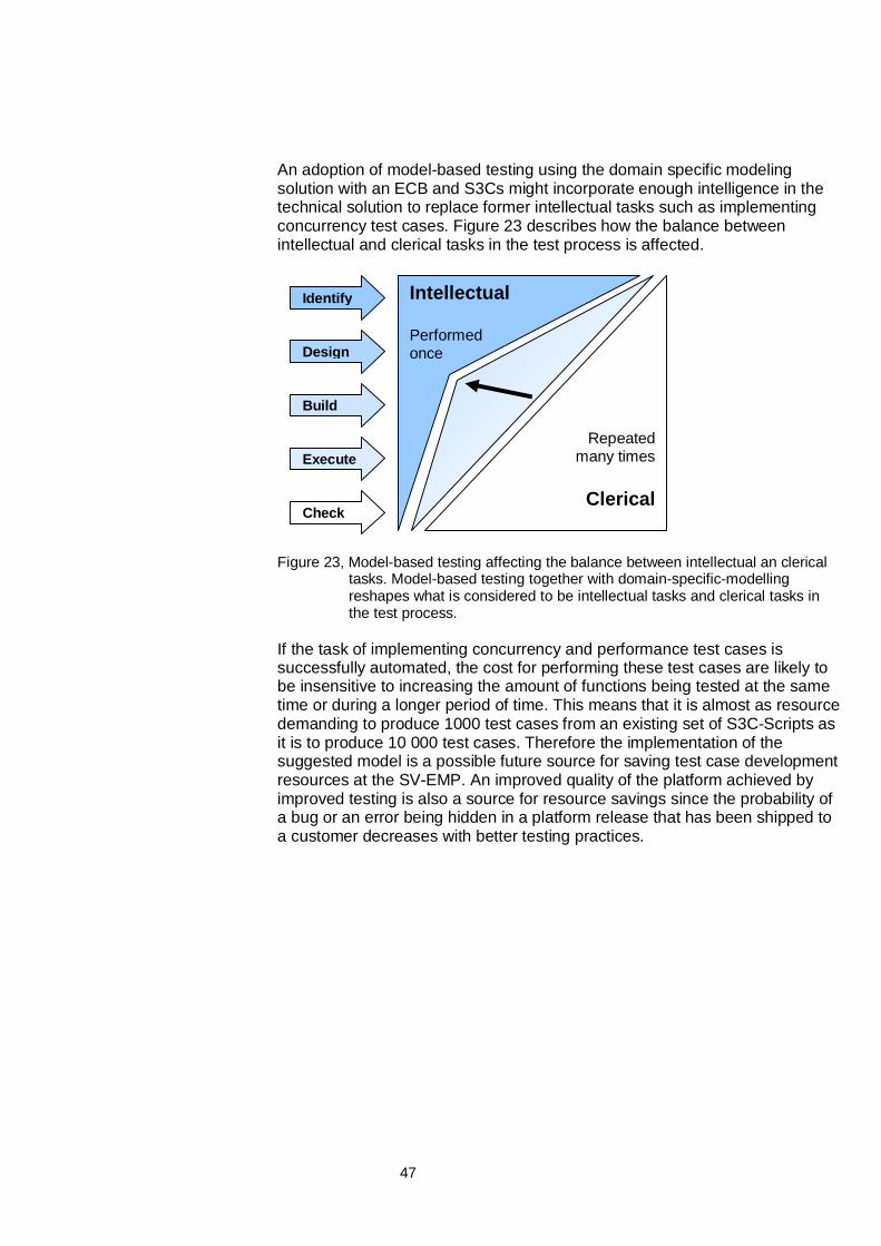
47
An adoption of model-based testing using the domain specific modelingsolution with an ECB and S3Cs might incorporate enough intelligence in thetechnical solution to replace former intellectual tasks such as implementingconcurrency test cases. Figure 23 describes how the balance betweenintellectual and clerical tasks in the test process is affected.
Figure 23, Model-based testing affecting the balance between intellectual an clericaltasks. Model-based testing together with domain-specific-modellingreshapes what is considered to be intellectual tasks and clerical tasks inthe test process.
If the task of implementing concurrency and performance test cases issuccessfully automated, the cost for performing these test cases are likely tobe insensitive to increasing the amount of functions being tested at the sametime or during a longer period of time. This means that it is almost as resourcedemanding to produce 1000 test cases from an existing set of S3C-Scripts asit is to produce 10 000 test cases. Therefore the implementation of thesuggested model is a possible future source for saving test case developmentresources at the SV-EMP. An improved quality of the platform achieved byimproved testing is also a source for resource savings since the probability ofa bug or an error being hidden in a platform release that has been shipped toa customer decreases with better testing practices.
Identify
Design
Build
Execute
Check
Intellectual
Performedonce
Repeatedmany times
Clerical
48
5.3 Discussion
Major changes of the test system will have long term effects on the testingactivities at SV-EMP because of the amount of work needed to modify all theexisting code for test cases and the test platform. The long term strategy forimproving the testing activities also has to be aligned with the long termstrategies for product development, in order to achieve good performance inthe product development process. Trends in the telecom industry typicallycome fast and strike hard, forcing the telecom companies to be able to quicklyadopt to new technologies and work methods. Therefore is it important thatSV-EMP does not get locked up in fixed non-adaptable work structures andtechnical support systems, such as a test systems designed for a specificmobile platform that could be obsolete in a short time. The suggested modelfor how to construct and execute test cases is based on the structuralbehavioral model of a mobile platform described in Figure 14 in 3.2. If thismodel changes, the test system has to adapt to that.
Since the S3C-Concept describes an S3C as a single functionality automatedtest case that is designed for among other things parallel execution, this iswhat has been considered the only content of an S3C in this master’s thesis.But in the implemented prototype there are really no limitations that prohibitthe S3C model from being used in other types of test case implementations. Aconcurrency test case could for example be transformed into a single S3Cand prepared for parallel execution with other S3Cs or some of the measuringdone for verifying test cases could be extracted into a measuring S3C thatmonitors the platform while other S3Cs execute test cases.
49
6 Conclusions and Future work
6.1 Conclusions
The implementation of the S3C-Concept shows that the parallel execution oftest cases to construct a concurrency and performance test cases works. Thismeans that the existing test cases used today at SV-EMP, with a varyingamount of modifications to transform them into S3C-Scripts, can be executedin parallel to form an S3C/ECB-Test. However, the implementation alsorevealed that a full implementation of the concept would require a redesign ofmajor parts of the test system, in order to achieve good quality in terms of:stability, traceability for errors and enabling the creation of specific testscenarios for the test cases.
The test cases that are produced by the parallel execution of S3C-Scriptsresemble the actual usage of a mobile platform more than the existing testcases do at present. The parallel executions of S3C-Scripts are thereforemore suitable to use for testing the concurrency and performance abilities ofthe mobile platform and its asynchronous OPA interface, see chapter 5.2.1.
The evaluation also reveals some of the effects on the test process that anadoption to model-based testing would imply in terms of automating test casegeneration by using domain-specific modeling. The process changesimplicate possible resource savings through increased automation andchanges to input and output in phase one and two in the System Verificationwork process. The decision of how autonomous the S3C-Scripts should beaffects the level of automation of test case generation since a solution with anextensive script controlling the execution resembles the technical solutionused today and is more difficult to automate. A solution with self dependentS3C-Scripts would be better suited to put to account the benefits ofautomation but requires a more complicated and extensive implementation.
6.2 Future work
The prototype developed during the work with this master’s thesis was usedfor evaluating the S3C-Concept and is not intended to be incorporated intoSV-EMP’s test system. The main structure with an ECB written in aprogramming language supporting TCP/IP communication and the S3C-Scripts written in LabVIEW™ along with the technical solution for thecommunication between the two different programming languages, could beconsidered as a good and scalable solution for implementing the S3C-Concept at SV-EMP. If the prototype is to be enhanced to be able to handle afull scale implementation at SV-EMP it needs further work with stability issuesdiscussed in chapter 5.1.1 and the S3C-Scripts has to be developed further tobe able to cope with conflicting measurements also discussed in chapter5.1.5.
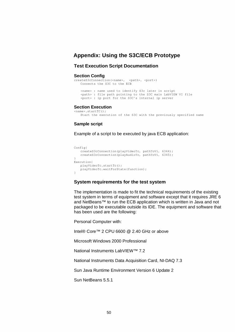
50
Appendix: Using the S3C/ECB Prototype
Test Execution Script Documentation
Section ConfigcreateS3cConnection(<name>, <path>, <port>)
Connects the S3C to the ECB
<name> : name used to identify S3c later in script<path> : file path pointing to the S3C main LabVIEW VI file<port> : ip port for the S3C’s internal ip server
Section Execution<name>.startTC();
Start the execution of the S3C with the previously specified name
Sample script
Example of a script to be executed by java ECB application:
Config{createS3cConnection(playVideoTc, pathToVi, 6344);createS3cConnection(playAudioTc, pathToVi, 6345);
}Execution{
playVideoTc.startTc();playVideoTc.waitForState(function);
}
System requirements for the test system
The implementation is made to fit the technical requirements of the existingtest system in terms of equipment and software except that it requires JRE 6and NetBeans™ to run the ECB application which is written in Java and notpackaged to be executable outside its IDE. The equipment and software thathas been used are the following:
Personal Computer with:
Intel® Core™ 2 CPU 6600 @ 2.40 GHz or above
Microsoft Windows 2000 Professional
National Instruments LabVIEW™ 7.2
National Instruments Data Acquisition Card, NI-DAQ 7.3
Sun Java Runtime Environment Version 6 Update 2
Sun NetBeans 5.5.1
51
Appendix: Distribution of work
Most of the work has been performed collectively and it is thereforeimpossible to specify the individual contributions with good accuracy.However, an approximate distribution of responsibilities between the twoauthors of this master’s thesis would be the following:
Mats Olin:
Report: Chapter 1, 2.2, 3.2, 5, 6
Implementation: ECB-Tool, S3C-Script LD_VC.
Carl Wykman:
Report: Chapter 1, 2.1, 2.3, 3.1, 4, 6
Implementation: ECB-Tool, S3CRunServer, S3C-Script SMS, S3C-ScriptDateTime.
52
Glossary
General; Software Testing
API
An application programming interface (API) is a source code interface that acomputer system or program library provides to support requests for servicesto be made of it by a computer program.
Black Box Testing
A test specification technique that is based on inputs and outputs from thesystem. Black box testing is based on functional specifications and qualityrequirements.
Concurrency test
A test case that tests the systems ability to handle simultaneous actions andprocesses. The purpose is to determine the effects of accessing the sameapplication code, module or database records.
Performance Test
How fast a system is performing tasks is called a performance qualitycharacteristic. Performance is specified as the number of tasks that should beexecuted during a certain time limit. These specification numbers is derivedfrom tests using a simulated system or a previously developed version of asimilar system.
Performance is tested either explicitly using real-life tests or implicitly bycollecting metrics from tested aimed at functionality (Pol et al 2002, p.141).
Regression Test
A test meant to verify that the system as a whole functions as it is supposedto. It is aimed at finding regressions in the system. A regression is a defectthat shows up in an unchanged part of the system due to a change in anotherpart of the system. This is why the whole system needs to be tested duringregression testing.
SUT, System under test
A general entitlement of the whole system that is to be tested.
System Test
In this document system test or system verification is performed on an officialbuild of the platform software, where all platform functionality has beenintegrated according to the requirements baseline.
53
Test
Test is the process of executing or evaluating a system by manual orautomatic methods, in order to verify that it fulfills specified requirements or todiscover differences between expected and perceived results.
UC - Use Case
A UC is a system requirement description that consists of a complete set ofactions initiated by an actor (user). The test cases at Ericsson are constructedfrom the UC that constitute requirement specification for the platform.
Verification
The verification decides whether the developed artifacts correspond to therequirements of the artifact. Testing the artifact may be one way of performingthe verification.
White Box Test Technique
A test specification technique based on the person developing test caseshaving access to the program code and the technical design.
54
Specific Ericsson Mobile Platform Nomenclature
DUT – Device Under Test
The system on which the tests are performed e.g. a platform flashed withcertain software release. Could be either a “Small Board” or a “Big Board”.
ECB – Execution Control Board
An ECB is a software unit that controls the construction and execution of testcases consisting of one or more S3C
Platform
A platform is a circuit-board with added functionality (software) that forms thebase in a mobile phone.
S3C – Self-Contained Container Concept
An S3C is a software unit which contains a compete test case handling asingle functionality. An S3C can be executed stand-alone or in a suite withother S3C to build up a concurrency test case.
Software Backplane
The part of the software in the platform that is reached through OPA
Test Bed, Test Station
The physical equipment and the software used to execute a test case e.g. aPC and one or more DUTs connected by a cable.
VI, LabVIEW™
Part of code written in the graphical programming language used in thesoftware LabVIEW™ and executed in LabVIEW™. It can act both as a sub-function called by other Vis and as a main method meant to be run by theuser.
55
References
Höst, Martin, Regnell, Björn, Runeson, Per. 2006, Att genomföraexamensarbete, Studentlitteratur
ISO/IEC FCD 9126-1, 2001. Part 1: Information Technology - SoftwareProduct Quality - Part 1: Quality Model. International Organization ofStandardization
Burnstein, I. 2003, Practical Software Testing, Springer
Pol, M., Teunissen, R., Veenendaal, E. 2002, Software Testing, AddisonWesley
Fewster, Mark, Graham, Dorothy. 1999, Software test automation: Effectiveuse of test execution tools, Addison Wesley
Scacchi 2001, Process Models in Software Engineering, Institute for SoftwareResearch, University of California, Irvine, USA, 2007-04-25(http://www.ics.uci.edu/~wscacchi/Papers/SE-Encyc/Process-Models-SE-Encyc.pdf)
Botincan, M., Novakovic, V. 2007, Model-based Testing of the ConferenceProtocol with Spec Explorer, ConTel 2007. 9th International Conference on13-15 June 2007 Page(s):131 – 138
Pretschner, A. 2005, Model-based testing, Software Engineering, ICSE.Proceedings. 27th International Conference on 15-21 May 2005 Page(s):722 -723
Katara, M., Kervinen, A., Maunumaa, M., Paakkonen, T., Satama, M. 2006.Towards Deploying Model-Based Testing with a Domain-Specific ModelingApproach, Testing: Academic Industrial Conference - Practice And ResearchTechniques (TAIC PART'06) Pages 81-89.
IEEE 1990, IEEE Standard Glossary of Software Engineering Terminology,std 610.12-1990
Ericsson patent document, A Method And A System For Software Testing (P-21560)
National Instruments™ website, 2007-04-27 (www.ni.com)
Software Process Models, The Software-Experts Quality Software Services,Germany, 2007-05-07 (http://www.the-software-experts.de/e_dta-sw-process.htm)
Domain Specific Modeling Forum website, 2007-08-04(http://www.dsmforum.org)

56
C. Andersson, P. Runeson, “A Replicated Quantitative Analysis of FaultDistributions in Complex Software System” IEEE Transactions on SoftwareEngineering, May 2007 (Vol. 33, No. 5) pp. 273-286