Embed Size (px)
Citation preview
Evaluating and Correcting Subsynchronous Vibration in Vertical Pumps
ByMalcolm E. Leader, P.E.
Applied Machinery Dynamics Co.Kelly J. Conner – Lyondell-BassellJamie D. Lucas – Lyondell-Bassell
Abstract
New vertical pumps were installed in liquid sulfur service. They were soon found to have
unacceptable levels of subsynchronous vibration near half running speed. The operating speed of
the induction motor driven pumps was 3,575 RPM and the largest vibration component was
detected at 1,750 CPM. Since the pump itself was submerged 12 feet below the top of the vessel,
vibration measurements were made on the motor. Laterally, in some cases, up to 1.5 inches-per-
second of this subsynchronous vibration was measured on the top of the motor. Vibration
analysis including impact testing revealed that there were structural resonances near half running
speed. The excitation was believed to be coming from the liquid sulfur-lubricated pump line
shaft bushings being in whirl similar to the familiar oil whirl. A rotordynamics study concluded
that there was sulfur whirl occurring and that the first lateral critical speed of the pump line shaft
was also at half frequency. New line shaft bushings were designed that would increase the
effective stiffness and damping from the bushings. Once the new bushings were installed, the
subsynchronous vibration was eliminated.
Introduction
These pumps, which are used to pump liquid sulfur at 300°F, are a single-stage vertical
design with a motor mounted on top over an adaptor support containing the flexible coupling and
a seal. A long (approximately 12 feet) line shaft reaches down into a large sump where the
impeller and volute sit near the bottom. There are four bearings/bushings. The dynamically
controlling bearings are the two in the middle of the line shaft. The existing bushing material is
nickel-based carbon graphite suitable for liquid sulfur service. The units are 40 HP and rated at
81 GPM at 219 feet of head at a nominal operating speed of 3,575 RPM. The pump and line
shaft are a jacketed design to insure that the sulfur temperature is maintained at its optimum
pumping temperature.
1
Dyrobes Rotordynamics Software https://dyrobes.com
A Houston refinery completed a capital project for sulfur unit expansion which consisted
of the purchase and installation of six upgraded sulfur pit pumps. The pumps were designated
for paired installation in three separate pits. The pumps were successfully installed in the first
vessel enclosed pit during a previous unit maintenance interval during late 2008, but problems
occurred during the attempted late spring 2009 installation into the older cement type pits due to
material build-up. These remaining pits were identical in design and mirror-imaged in
connections.
Over the years of operation, “sulcrete” had formed around the currently installed pumps
creating a valley allowing their inserting and operation. Sulcrete is a very hard sulfur-concrete
material formed around the pump from steam leaks into the pits. The new pumps were laterally
offset approximately one foot preventing the pump bottom from being placed in the same
location. Based on operational and safety concerns about shutting down the units to allow the
pits to be properly cleaned, it was determined that raising the elevation of the pumps would
allow their insertion and operation into a clear pit area until the next scheduled outage. A new
structural steel base was built and installed. One base for each pit was made with two pumps per
base.
The base was installed and a bump tested completed. The natural frequency rang above
5,000 CPM. The first pump was installed in the interior (West) slot with shorter pipe runs.
When that pump was placed in service, elevated vibration was detected on the motor at 0.20 IPS
at approximately 1,710 CPM or slightly less than half of the 3,575 RPM pump speed. The
second pump was installed in the exterior (East) slot with longer piping runs. The seismic
vibration on this pump was recorded on the motor at over 0.65 IPS at approximately 1,750 CPM.
The slightly less than half times peak frequency was also noted in the two pumps placed
in the first pit at a much lower intensity. With this information, it was determined that there was
a “sulfur whirl” phenomena taking place in the journal bearings of all the pumps. A series of
bump tests were conducted with the pumps fully installed. The test results are shown in table 1.
Bump Test Location East-West Direction North-South Direction
East Pump 1,734 CPM 1,887 CPM
West Pump 1,657 CPM 1,887 CPM
Table 1 – Impact Test Measured Frequencies
2
It was concluded the pump had an excitation mechanism corresponding with the natural
frequency of the system. In a quick attempt to change the vibration, the coupling was changed to
a lower mass design which had already been chosen for maintenance simplification. That
change had no effect. There was also some discussion about modifying the structure and/or
piping to alter the structural resonances. However, unless a system is very flexible to start with,
stiffening is very difficult to apply effectively since adding braces also adds mass to the system.
Indeed, while stiffening may have reduced the measured vibrations above ground, the instability
in the pump bushings would have remained. Thus, a rotordynamics analysis was initiated.
Vibration Measurements
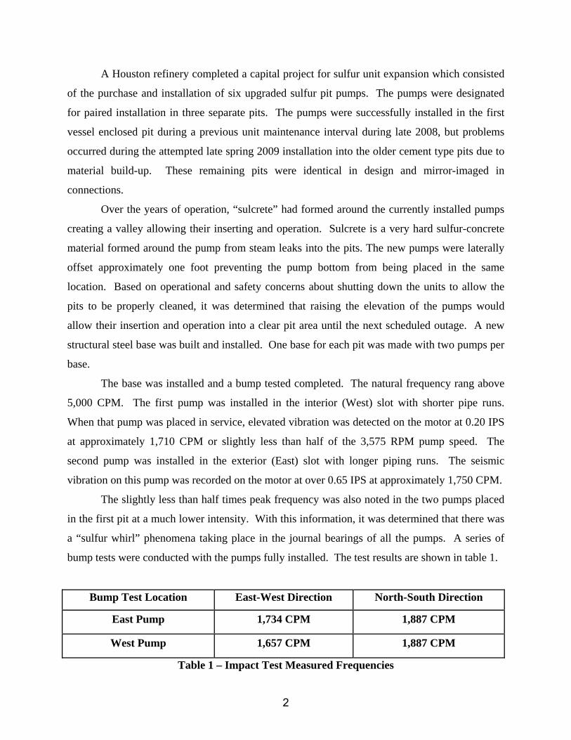
High vibration was found immediately during initial runs of the new pumps. Figure 1
indicates that virtually all of the vibration was subsynchronous at about half-speed.
Figure 1 – Seismic Vibration from Top of New Sulfur Pump Installation
Operating speed vibration near 3,575 RPM is virtually non-existent in this spectrum.
While this is a typical result, some pumps had higher vibration and some were lower but all
exhibited the subsynchronous vibration as the primary component.
3
Rotordynamics Analysis
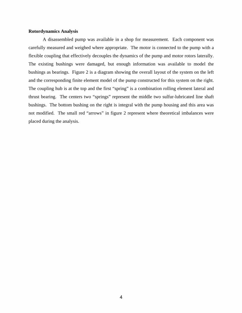
A disassembled pump was available in a shop for measurement. Each component was
carefully measured and weighed where appropriate. The motor is connected to the pump with a
flexible coupling that effectively decouples the dynamics of the pump and motor rotors laterally.
The existing bushings were damaged, but enough information was available to model the
bushings as bearings. Figure 2 is a diagram showing the overall layout of the system on the left
and the corresponding finite element model of the pump constructed for this system on the right.
The coupling hub is at the top and the first “spring” is a combination rolling element lateral and
thrust bearing. The centers two “springs” represent the middle two sulfur-lubricated line shaft
bushings. The bottom bushing on the right is integral with the pump housing and this area was
not modified. The small red “arrows” in figure 2 represent where theoretical imbalances were
placed during the analysis.
4
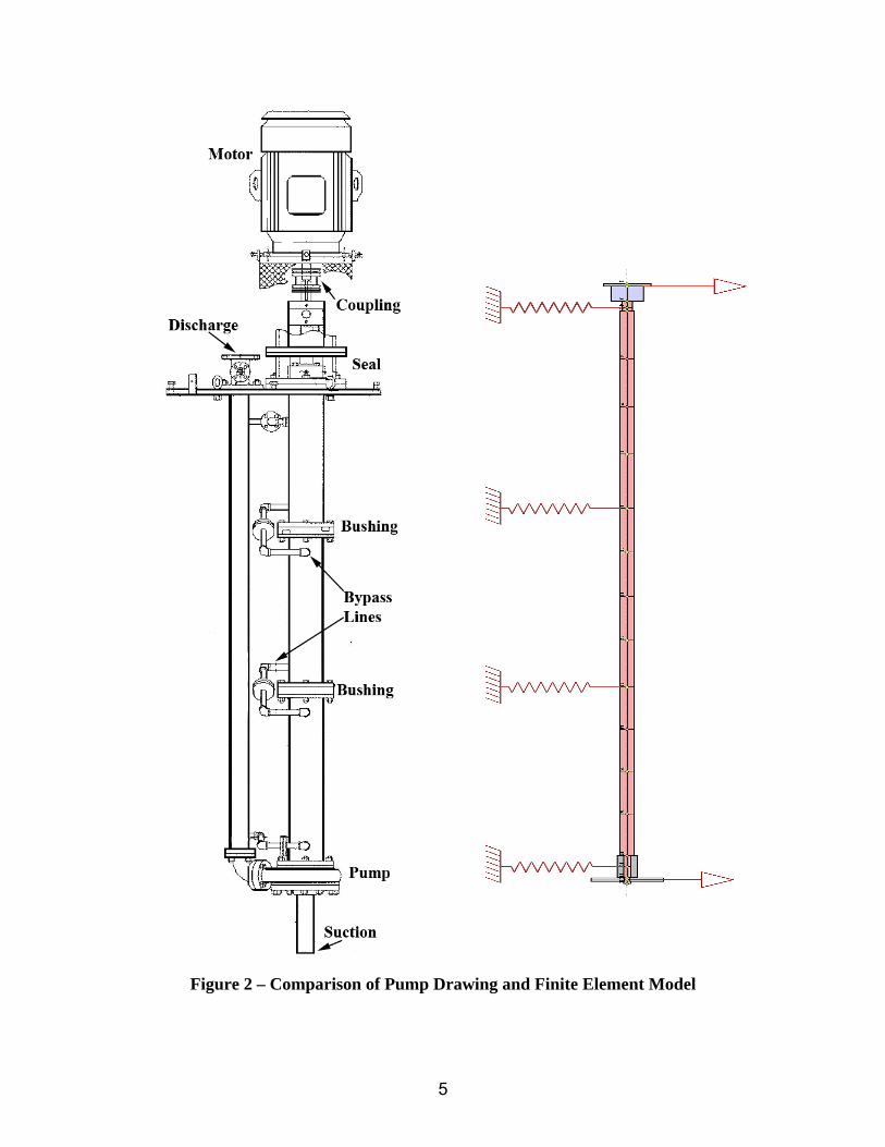
Figure 2 – Comparison of Pump Drawing and Finite Element Model
5
The pump line shaft is 144 inches long and 2.5 inches in diameter. The spacing between
the two center bushings is 48.75 inches. Sleeves are keyed and set-screwed onto the shaft at the
two center-span bushing locations. Originally these sleeves contained a spiral-groove as seen on
the left in figure 3. The redesigned sleeve without the spiral groove is shown for comparison on
the right. The spiral groove was thought to be necessary to induce liquid sulfur flow vertically.
This groove was eliminated in the final design since it was determined that there is sufficient
pressure differential across the bushings to ensure adequate lubrication.
Figure 3 – Original and Redesigned Shaft Sleeves
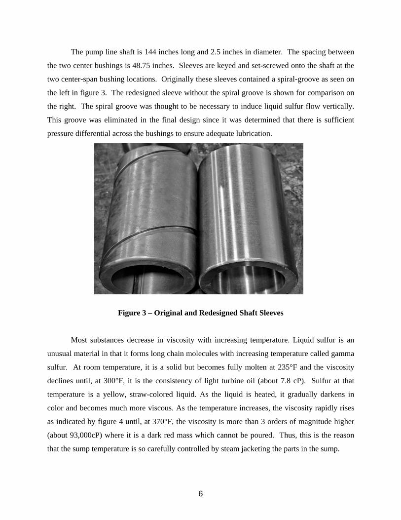
Most substances decrease in viscosity with increasing temperature. Liquid sulfur is an
unusual material in that it forms long chain molecules with increasing temperature called gamma
sulfur. At room temperature, it is a solid but becomes fully molten at 235°F and the viscosity
declines until, at 300°F, it is the consistency of light turbine oil (about 7.8 cP). Sulfur at that
temperature is a yellow, straw-colored liquid. As the liquid is heated, it gradually darkens in
color and becomes much more viscous. As the temperature increases, the viscosity rapidly rises
as indicated by figure 4 until, at 370°F, the viscosity is more than 3 orders of magnitude higher
(about 93,000cP) where it is a dark red mass which cannot be poured. Thus, this is the reason
that the sump temperature is so carefully controlled by steam jacketing the parts in the sump.
6
Figure 4 – Viscosity of Sulfur at Various Temperatures
Figure 5 is a cross-section of the original bushing design. These bushings were 3.375
inches in diameter and 4.25 inches long. The nominal diametral clearance was 16 mils. The
load “W” indicated by the red arrow was zero for all the bushing analyses during this study.
In a vertical orientation there is very little radial load between the pump shaft and the
stationary bushings. In this condition, virtually all plain bushings are inherently unstable. They
simply cannot generate a sufficient hydrodynamic pressure field that will hold the shaft at a
stable equilibrium point. Thus, a profile design was conceived consisting of three lobes that
would each generate a stable pressure field that would center the journal in the bushing and
provide both significant radial stiffness and damping.
7
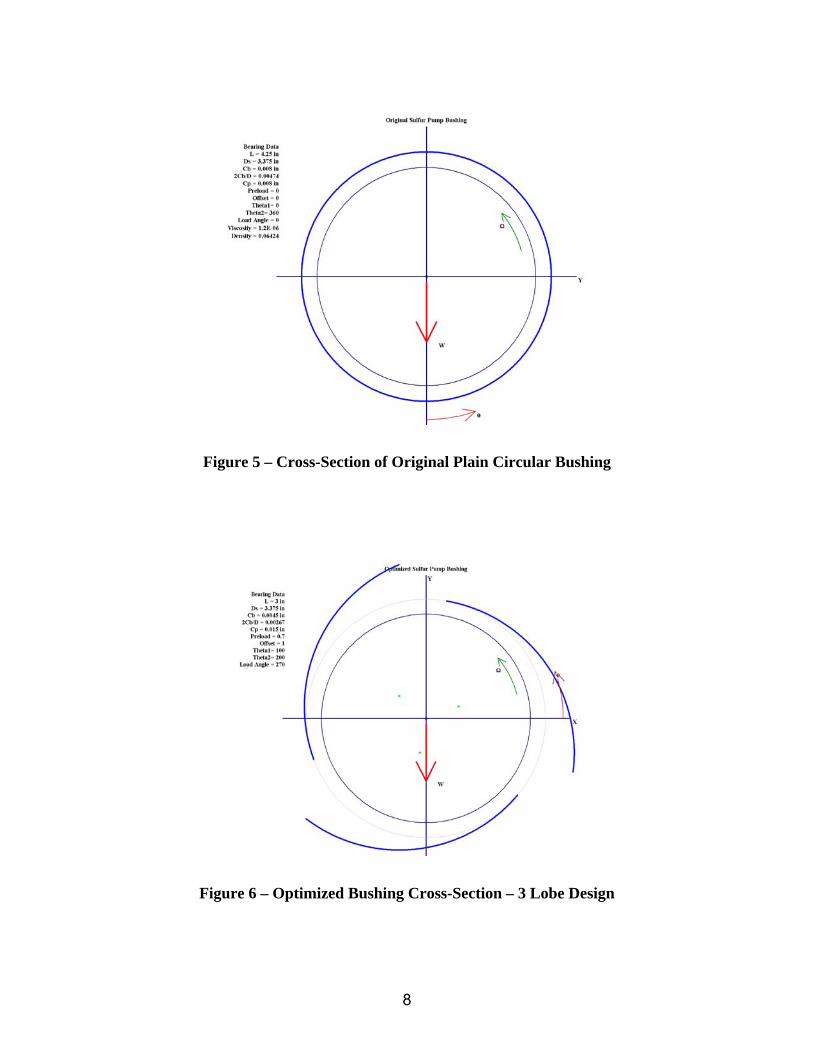
Figure 5 – Cross-Section of Original Plain Circular Bushing
Figure 6 – Optimized Bushing Cross-Section – 3 Lobe Design
8
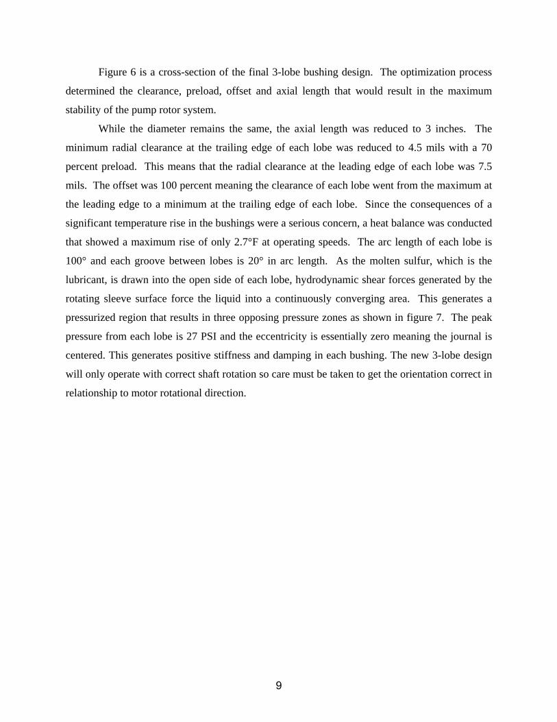
Figure 6 is a cross-section of the final 3-lobe bushing design. The optimization process
determined the clearance, preload, offset and axial length that would result in the maximum
stability of the pump rotor system.
While the diameter remains the same, the axial length was reduced to 3 inches. The
minimum radial clearance at the trailing edge of each lobe was reduced to 4.5 mils with a 70
percent preload. This means that the radial clearance at the leading edge of each lobe was 7.5
mils. The offset was 100 percent meaning the clearance of each lobe went from the maximum at
the leading edge to a minimum at the trailing edge of each lobe. Since the consequences of a
significant temperature rise in the bushings were a serious concern, a heat balance was conducted
that showed a maximum rise of only 2.7°F at operating speeds. The arc length of each lobe is
100° and each groove between lobes is 20° in arc length. As the molten sulfur, which is the
lubricant, is drawn into the open side of each lobe, hydrodynamic shear forces generated by the
rotating sleeve surface force the liquid into a continuously converging area. This generates a
pressurized region that results in three opposing pressure zones as shown in figure 7. The peak
pressure from each lobe is 27 PSI and the eccentricity is essentially zero meaning the journal is
centered. This generates positive stiffness and damping in each bushing. The new 3-lobe design
will only operate with correct shaft rotation so care must be taken to get the orientation correct in
relationship to motor rotational direction.
9
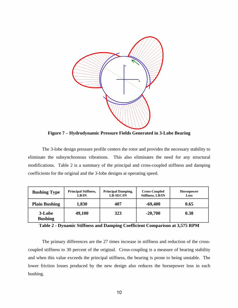
Figure 7 – Hydrodynamic Pressure Fields Generated in 3-Lobe Bearing
The 3-lobe design pressure profile centers the rotor and provides the necessary stability to
eliminate the subsynchronous vibrations. This also eliminates the need for any structural
modifications. Table 2 is a summary of the principal and cross-coupled stiffness and damping
coefficients for the original and the 3-lobe designs at operating speed.
Bushing Type Principal Stiffness, LB/IN
Principal Damping, LB-SEC/IN
Cross-Coupled Stiffness, LB/IN
Horsepower Loss
Plain Bushing 1,830 407 -69,400 0.65
3-Lobe Bushing
49,100 323 -20,700 0.38
Table 2 - Dynamic Stiffness and Damping Coefficient Comparison at 3,575 RPM
The primary differences are the 27 times increase in stiffness and reduction of the cross-
coupled stiffness to 30 percent of the original. Cross-coupling is a measure of bearing stability
and when this value exceeds the principal stiffness, the bearing is prone to being unstable. The
lower friction losses produced by the new design also reduces the horsepower loss in each
bushing.
10
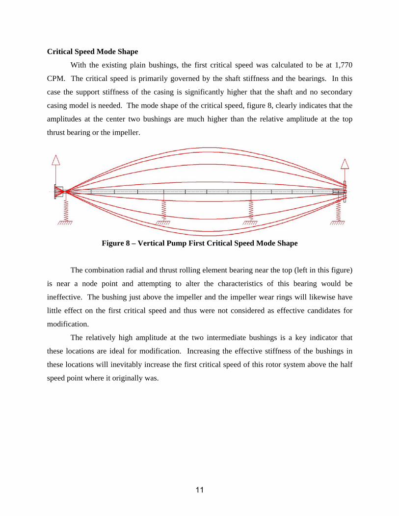
Critical Speed Mode Shape
With the existing plain bushings, the first critical speed was calculated to be at 1,770
CPM. The critical speed is primarily governed by the shaft stiffness and the bearings. In this
case the support stiffness of the casing is significantly higher that the shaft and no secondary
casing model is needed. The mode shape of the critical speed, figure 8, clearly indicates that the
amplitudes at the center two bushings are much higher than the relative amplitude at the top
thrust bearing or the impeller.
Figure 8 – Vertical Pump First Critical Speed Mode Shape
The combination radial and thrust rolling element bearing near the top (left in this figure)
is near a node point and attempting to alter the characteristics of this bearing would be
ineffective. The bushing just above the impeller and the impeller wear rings will likewise have
little effect on the first critical speed and thus were not considered as effective candidates for
modification.
The relatively high amplitude at the two intermediate bushings is a key indicator that
these locations are ideal for modification. Increasing the effective stiffness of the bushings in
these locations will inevitably increase the first critical speed of this rotor system above the half
speed point where it originally was.
11
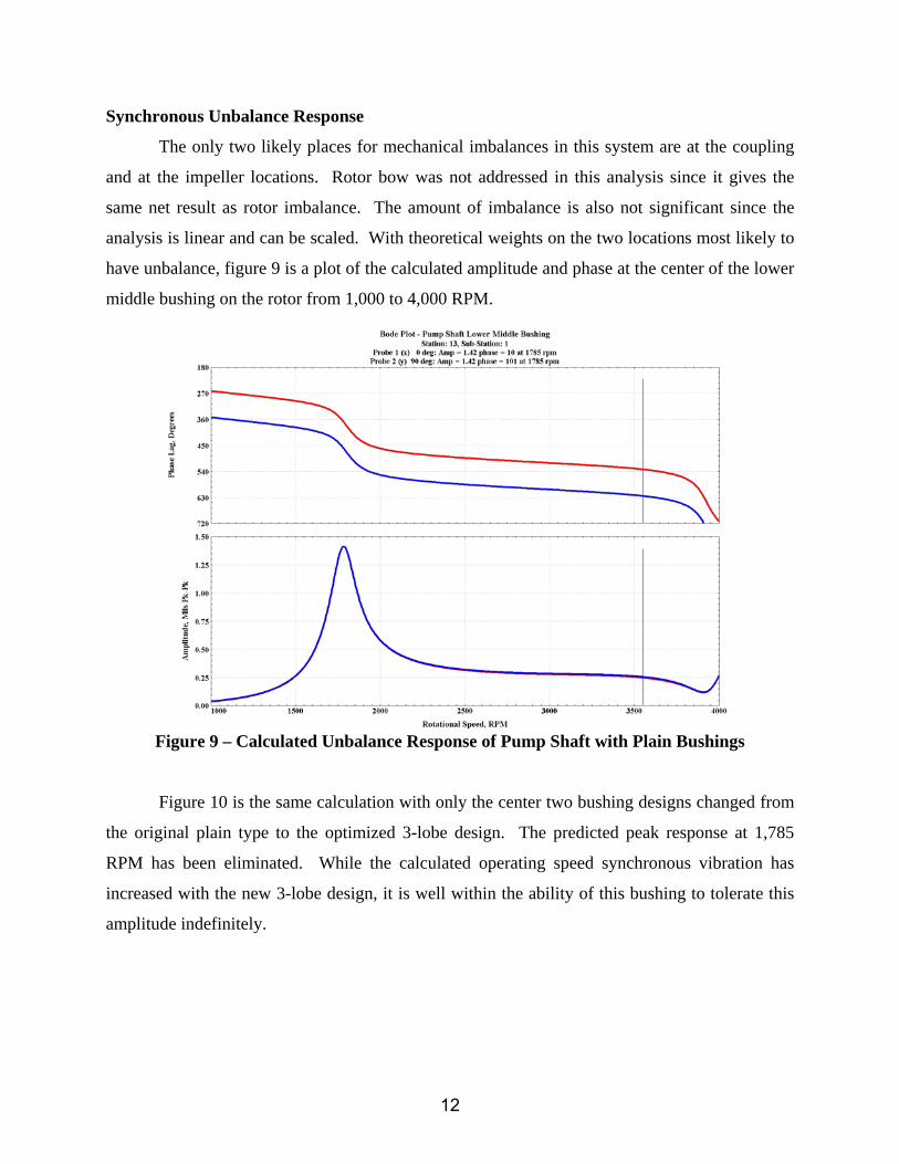
Synchronous Unbalance Response
The only two likely places for mechanical imbalances in this system are at the coupling
and at the impeller locations. Rotor bow was not addressed in this analysis since it gives the
same net result as rotor imbalance. The amount of imbalance is also not significant since the
analysis is linear and can be scaled. With theoretical weights on the two locations most likely to
have unbalance, figure 9 is a plot of the calculated amplitude and phase at the center of the lower
middle bushing on the rotor from 1,000 to 4,000 RPM.
Figure 9 – Calculated Unbalance Response of Pump Shaft with Plain Bushings
Figure 10 is the same calculation with only the center two bushing designs changed from
the original plain type to the optimized 3-lobe design. The predicted peak response at 1,785
RPM has been eliminated. While the calculated operating speed synchronous vibration has
increased with the new 3-lobe design, it is well within the ability of this bushing to tolerate this
amplitude indefinitely.
12
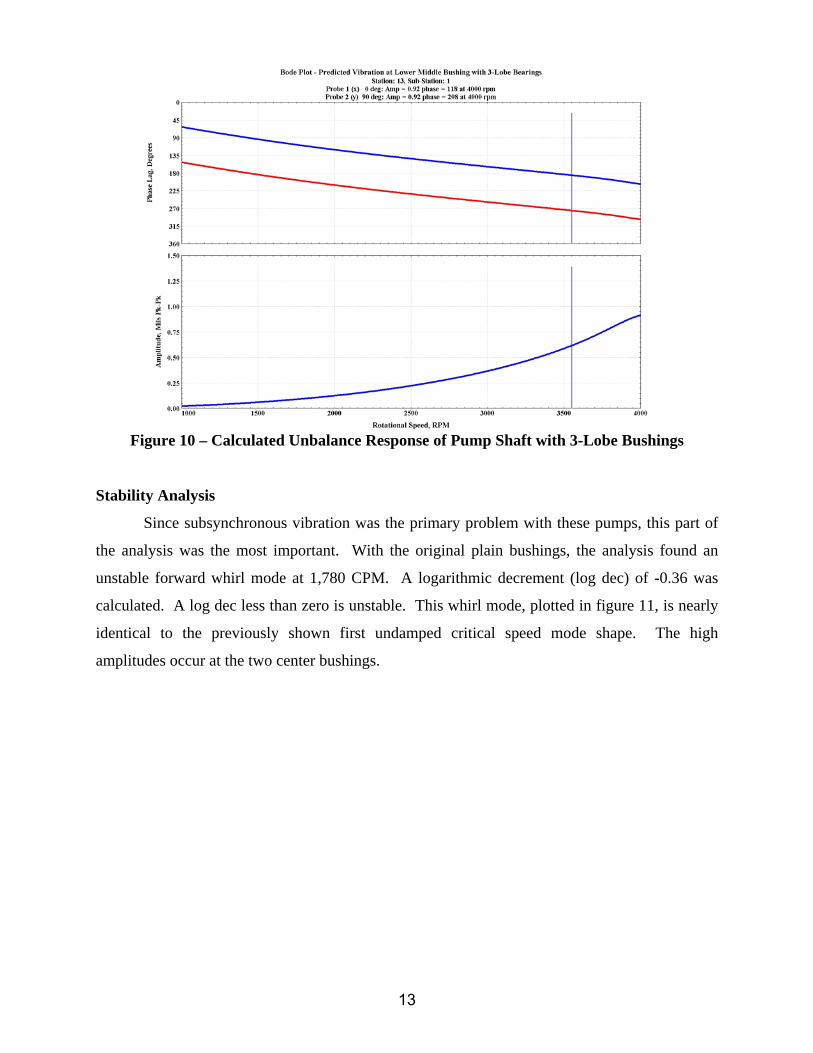
Figure 10 – Calculated Unbalance Response of Pump Shaft with 3-Lobe Bushings
Stability Analysis
Since subsynchronous vibration was the primary problem with these pumps, this part of
the analysis was the most important. With the original plain bushings, the analysis found an
unstable forward whirl mode at 1,780 CPM. A logarithmic decrement (log dec) of -0.36 was
calculated. A log dec less than zero is unstable. This whirl mode, plotted in figure 11, is nearly
identical to the previously shown first undamped critical speed mode shape. The high
amplitudes occur at the two center bushings.
13
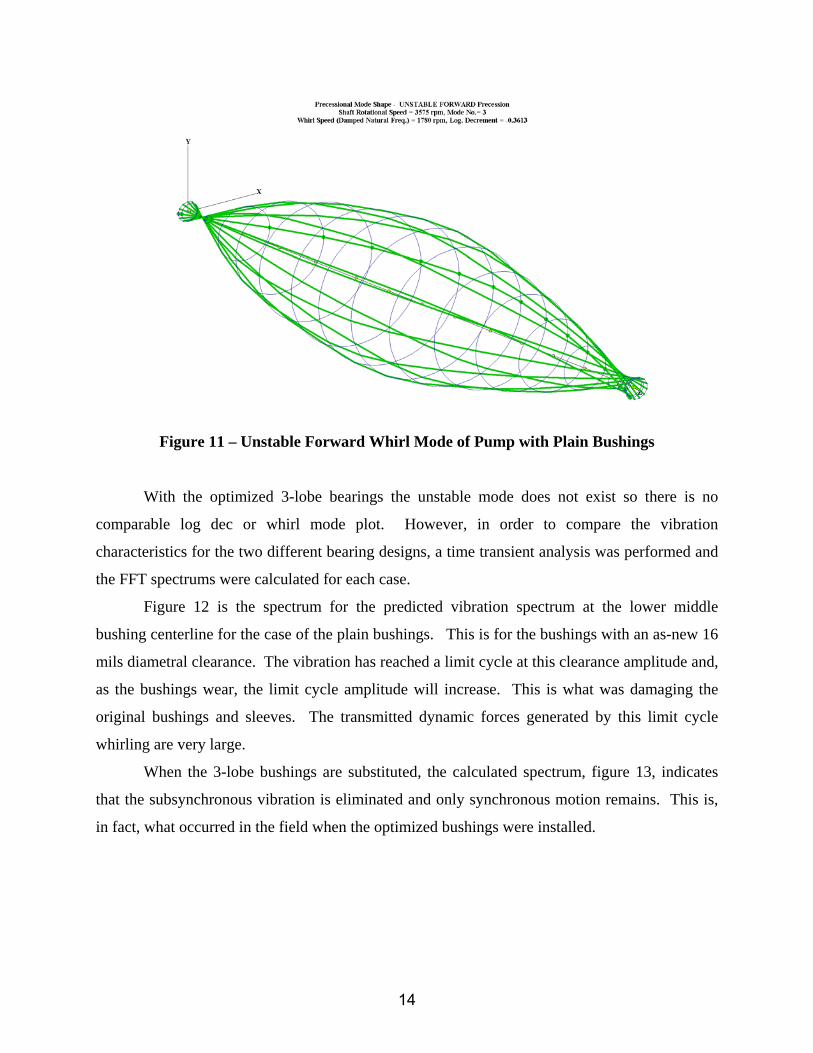
Figure 11 – Unstable Forward Whirl Mode of Pump with Plain Bushings
With the optimized 3-lobe bearings the unstable mode does not exist so there is no
comparable log dec or whirl mode plot. However, in order to compare the vibration
characteristics for the two different bearing designs, a time transient analysis was performed and
the FFT spectrums were calculated for each case.
Figure 12 is the spectrum for the predicted vibration spectrum at the lower middle
bushing centerline for the case of the plain bushings. This is for the bushings with an as-new 16
mils diametral clearance. The vibration has reached a limit cycle at this clearance amplitude and,
as the bushings wear, the limit cycle amplitude will increase. This is what was damaging the
original bushings and sleeves. The transmitted dynamic forces generated by this limit cycle
whirling are very large.
When the 3-lobe bushings are substituted, the calculated spectrum, figure 13, indicates
that the subsynchronous vibration is eliminated and only synchronous motion remains. This is,
in fact, what occurred in the field when the optimized bushings were installed.
14
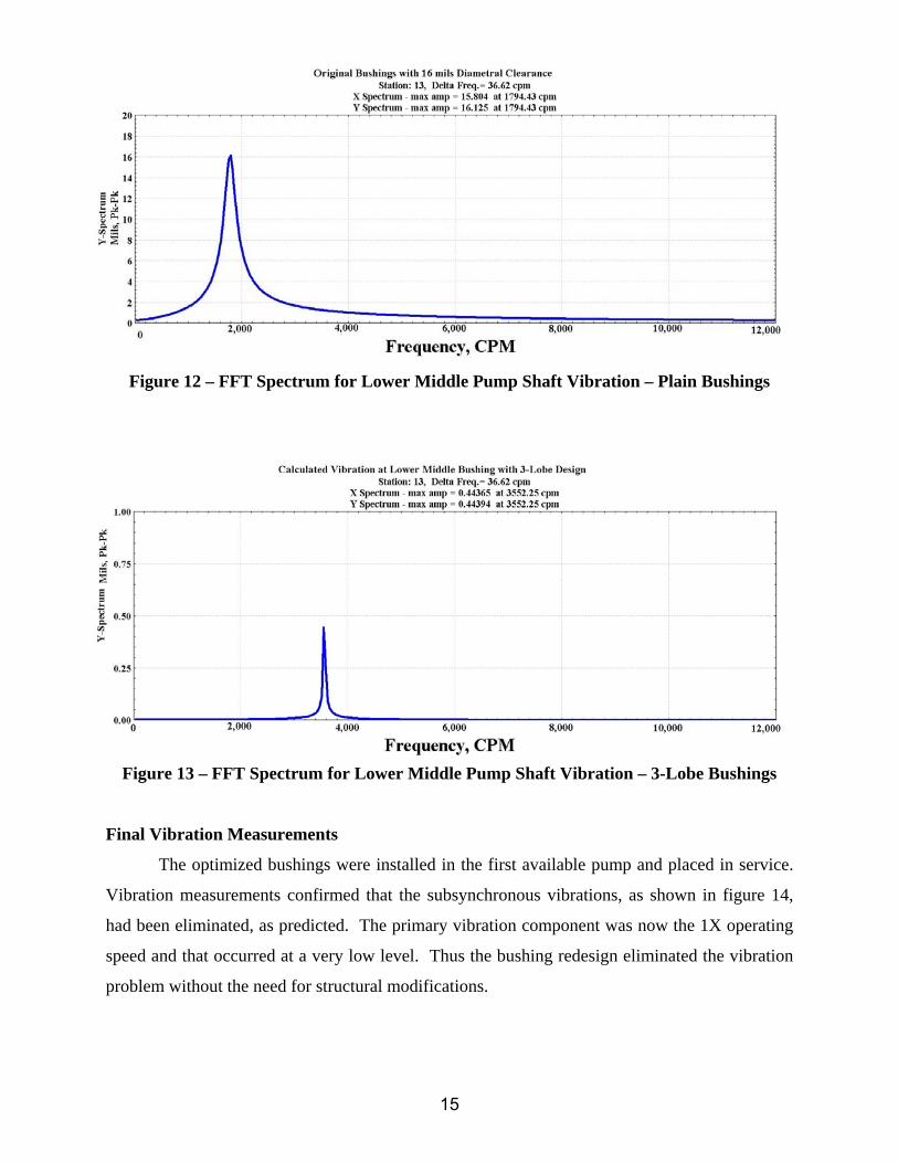
Figure 12 – FFT Spectrum for Lower Middle Pump Shaft Vibration – Plain Bushings
Figure 13 – FFT Spectrum for Lower Middle Pump Shaft Vibration – 3-Lobe Bushings
Final Vibration Measurements
The optimized bushings were installed in the first available pump and placed in service.
Vibration measurements confirmed that the subsynchronous vibrations, as shown in figure 14,
had been eliminated, as predicted. The primary vibration component was now the 1X operating
speed and that occurred at a very low level. Thus the bushing redesign eliminated the vibration
problem without the need for structural modifications.
15
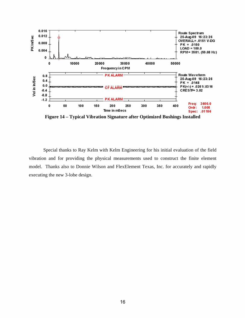
Figure 14 – Typical Vibration Signature after Optimized Bushings Installed
Special thanks to Ray Kelm with Kelm Engineering for his initial evaluation of the field
vibration and for providing the physical measurements used to construct the finite element
model. Thanks also to Donnie Wilson and FlexElement Texas, Inc. for accurately and rapidly
executing the new 3-lobe design.
16