Embed Size (px)
Citation preview

Chalmers University of Technology
University of Gothenburg
Department of Computer Science and Engineering
Göteborg, Sweden, June 2012
Evaluating a Design Pattern for Black-Box Testing in
Executable UML
Master of Science Thesis in the Programme Software Engineering and Technology
DANIEL ARVIDSSON
FREDRIK PERSSON

The Author grants to Chalmers University of Technology and University of Gothenburg
the non-exclusive right to publish the Work electronically and in a non-commercial
purpose make it accessible on the Internet.
The Author warrants that he/she is the author to the Work, and warrants that the Work
does not contain text, pictures or other material that violates copyright law.
The Author shall, when transferring the rights of the Work to a third party (for example a
publisher or a company), acknowledge the third party about this agreement. If the Author
has signed a copyright agreement with a third party regarding the Work, the Author
warrants hereby that he/she has obtained any necessary permission from this third party to
let Chalmers University of Technology and University of Gothenburg store the Work
electronically and make it accessible on the Internet.
Testing through Executable Software Modelling
DANIEL ARVIDSSON
FREDRIK PERSSON
© DANIEL ARVIDSSON, June 2012.
© FREDRIK PERSSON, June 2012.
Examiner: AGNETA NILSSON
Supervisor: ROGARDT HELDAL
Chalmers University of Technology
University of Gothenburg
Department of Computer Science and Engineering
SE-412 96 Göteborg
Sweden
Telephone + 46 (0)31-772 1000
Department of Computer Science and Engineering
Göteborg, Sweden, June 2012

i
Sammanfattning
Allt eftersom mjukvarusystem blir mer och mer komplexa så blir det även viktigare att ta fram
tillvägagångssätt för att göra mjukvaruutveckling mer effektivt. Modelldriven mjukvaruutveckling
(Model-Driven Development, MDD) ger oss möjligheter att hantera denna ständigt ökande
komplexitet. Testning har länge varit en kritisk del av mjukvaruutveckling och nya utmaningar
inom testning dyker upp när man anammar MDD.
För att möta dessa utmaningar och förskaffa oss med ett metodiskt tillvägagångssätt till testning
i MDD, utvärderar denna tes ett föreslaget designmönster. Detta mönster beskriver hur man kan
bygga körbara testmodeller som beskriver och verifierar förväntat beteende för systemet i
åtanke, med hjälp av ett abstrakt modelleringsspråk. Detta tillåter att testning genomförs både
på modell- och implementationsnivå genom modelltransformationer.
Utvärderingen genomfördes genom att ett antal implementationer skapades genom att följa det
föreslagna designmönstret. Varje implementation var skapad med specifika aspekter av
mönstret i åtanke. De observationer som gjorts under utvecklandet av implementationerna, ihop
med kunskap från relaterade arbeten, används för att dra slutsatser om det föreslagna
mönstret.

ii
Abstract
As software systems become more and more complex, finding ways to make software development more efficient is becoming more important. Model-Driven Development (MDD) presents us with possibilities to keep up with this ever increasing complexity. Testing has long been a critical part of software development, and new challenges in testing are introduced when adopting MDD. In an effort to face these challenges and provide a methodical approach to testing in MDD, this thesis evaluates a proposed design pattern. The pattern describes how to build an executable test model which describes and verifies expected behavior of the system under consideration, using a general-purpose modeling language. This allows testing to be done at both model- and code level through model transformation. The evaluation was done by creating a set of implementations using the proposed design pattern. Each implementation was intended to highlight specific aspects of the pattern. Knowledge gained by studying related work, together with observations made during the development of each implementation, was used to draw conclusions about the suggested design pattern.

iii
Acknowledgements We give our thanks to our academic supervisor Rogardt Heldal, who has provided invaluable input and feedback during work with both evaluation and report writing as well as providing the initial ideas behind the patterns laid out in this thesis. We also extend our thanks to Martin Lundqvist, our supervisor at Ericsson, for his input and daily support throughout the entire thesis work. We would also like to thank Toni Siljamäki for providing us with knowledge and support regarding BridgePoint and the transformation of models to source code. We thank Roland Carlsson for providing an implementation of a random number generator in BridgePoint. Finally, we thank Ericsson AB and the Baseband Research team at Ericsson Lindholmen for providing us with the opportunity to write this thesis in their care.

iv
Table of Contents 1. Introduction ............................................................................................................................ 1
1.1 Disposition ........................................................................................................................ 2
1.2 Glossary ........................................................................................................................... 2
2. Background ............................................................................................................................ 3
2.1 Software Modeling ............................................................................................................ 3
2.1.1 Model-Driven Development ........................................................................................ 3
2.1.2 Executable UML & Tool Support ................................................................................ 3
2.1.3 State machines .......................................................................................................... 4
2.1.4 Components ............................................................................................................... 4
2.2 Software Verification ......................................................................................................... 5
2.2.1 White-box and Black-box ........................................................................................... 5
2.2.2 Scenario-based testing............................................................................................... 6
2.2.3 Property-based testing ............................................................................................... 6
3. Research approach ................................................................................................................ 7
4. Theory .................................................................................................................................... 8
4.1 Test Environment ............................................................................................................. 8
4.2 Verification on multiple abstraction levels ......................................................................... 9
4.3 Modeling Expected Behavior ...........................................................................................10
5. Evaluation Setup ...................................................................................................................14
5.1 Systems under test ..........................................................................................................14
5.1.1 Microwave Oven .......................................................................................................14
5.1.2 Simple server application ..........................................................................................15
5.2 Implementations ..............................................................................................................16
5.2.1 Implementation 1: Testing Microwave Oven in BridgePoint .......................................16
5.2.2 Implementation 2: QuickCheck-inspired testing of server application ........................16
5.2.3 Implementation 3: QuickCheck-inspired testing of Microwave Oven..........................17
5.2.4 Implementation 4: Testing Microwave Oven in IBM RSA ...........................................17
6. Evaluation Results ................................................................................................................18
6.1 Results: Testing Microwave Oven in BridgePoint .............................................................18
6.2 Results: QuickCheck-inspired testing of server application ..............................................21
6.3 Results: QuickCheck-inspired testing of Microwave Oven ...............................................23
6.4 Results: Testing Microwave Oven in IBM RSA ................................................................26
7. Discussion ............................................................................................................................29
Hidden state .......................................................................................................................29
Distribution of Randomness ...............................................................................................29
Differences in modeling tools .............................................................................................30
Who watches the watchmen? ............................................................................................30
8. Related work .........................................................................................................................32
9. Conclusions and Future Work ...............................................................................................34
10. References..........................................................................................................................35
v
List of Figures Figure 1. Simple state machine. ................................................................................................. 4
Figure 2. Component configuration. ........................................................................................... 5
Figure 3. Test configuration. ....................................................................................................... 8
Figure 4. State machine for test engine class. ............................................................................ 8
Figure 5. Testing on multiple abstraction levels. ......................................................................... 9
Figure 6. Generate-validate pattern. ..........................................................................................10
Figure 7. Abstract representation of a generate-validate graph. ................................................11
Figure 8. Pattern for validating SUT response. ..........................................................................12
Figure 9. Example of generate-validate state machine. .............................................................12
Figure 10. Pseudo-code for validating confirmation of setting time. ...........................................13
Figure 11. State machine for a microwave oven. .......................................................................14
Figure 12. Action code in "Ensuring Safe to Cook" state. ..........................................................15
Figure 13. User interface of microwave oven component. .........................................................15
Figure 14. Interface provided by the server ...............................................................................16
Figure 15. Test case state machine in BridgePoint. ..................................................................18
Figure 16. Implementation of generate-validate pattern. ...........................................................19
Figure 17. Filter state machine. .................................................................................................20
Figure 18. State machine diagram representing a test case. .....................................................21
Figure 19. Pseudo-code for validation of registering value on server. .......................................22
Figure 20. State machine for the test engine class. ...................................................................23
Figure 21. State machine for the test case class. ......................................................................24
Figure 22. Pseudo-code for rudimentary shrinking algorithm. ....................................................25
Figure 23. Microwave Oven State Machine Diagram in IBM RSA. ............................................26
Figure 24. Test case state machine in IBM RSA. ......................................................................27
Figure 25. Graph where final states are at different depths. ......................................................30

1
1. Introduction
Developing software is rapidly becoming a major part of the business of large companies such
as Ericsson. As software systems become larger, more complex and more difficult to manage,
techniques and methods that make software development more efficient are becoming
increasingly interesting for these companies to benefit from. One of these methods is Model-
Driven Architecture (MDA) [1]. While MDA promises to help approach the issues faced, it also
presents new challenges and obstacles to overcome.
One of these challenges is the testing of software models. To facilitate testing, Object
Management Group (the consortium behind Model Driven Architecture) [2] has developed and
promoted the UML Testing Profile [3]. While the UML Testing Profile has shown to be a
promising technique, a need for more tool independent patterns has been identified [4]. One
study identified systematic patterns for testing as a particularly relevant field of research in
model-driven development efforts [5]. Such patterns have been studied, but it is suggested that
there are still challenges in testing software models when model transformation is introduced
[6].
The ability to transform models into source code when using executable modeling languages, together with an increased abstraction level in the developed executable models, means that tests could be written for systems at differing levels of abstraction. This enables test-driven development where executable specifications can be written as executable models independently of what platform the system is meant to run on. Since the cost of correcting errors increases with the time between the introduction and detection of the defect, this ability to discover and correct errors in an abstract model is one that could have a big impact on a project’s level of success [7, 8]. In this thesis we present and evaluate a design pattern for testing in software modeling. The pattern shows how to build executable test models where expectations on the behavior of the system under consideration are specified. For every input sent to the system, the expected response is specified. The pattern is evaluated by creating implementations using general-purpose modeling languages. The thesis poses the following research questions: How can a general design pattern be produced for building executable black-box test models using a general-purpose modeling language, with regards to: a. Tool independence? b. Mode of expression in implementation of the test model? c. Constraints put on the system under test? d. Ability to apply the pattern for testing at different abstraction levels? This master’s thesis was done at the Baseband Research department at Ericsson Lindholmen, Gothenburg. There have been experiments conducted concerning software development using executable software modeling in the past at Ericsson, and both tools and domain knowledge is available on-site.

2
1.1 Disposition
This report has nine chapters including this introducing chapter. Chapter one is an introduction to the thesis. It gives a rationale and purpose for the thesis, as well as presents the research question. Chapter two presents background information relevant to the research field of the thesis; software modeling and software verification. Chapter three describes the methods and approaches used in the thesis work. Chapter four presents the patterns and concepts that are subject to evaluation. Chapter five gives an overview of what implementations are made in order to analyze the design pattern subject to evaluation. Chapter six presents the results of each of the implementations created. Observations during the development process are gathered and interpreted here. Chapter seven discusses several topics arisen from the results of the implementations. Chapter eight gives an insight to other studies in the field and how they relate to the work done in this thesis. Chapter nine presents conclusions about the theories under evaluation, as well as discusses future work.
1.2 Glossary
UML - Unified Modeling Language, a modeling language offering graphical notations for abstractly describing structure and behavior.
xtUML - Executable and Translatable UML, a profile of UML to allow further expressiveness beyond what UML offers.
SUT - System under Test - The system in question which the effort of testing is focused on.
MDD - Model Driven Development
RSA - IBM Rational Software Architect, a tool developed by IBM that allows models to be constructed and verified using UML extended with an action language to express executable behavior.
BridgePoint - xtUML tool developed by Mentor Graphics.
Black-box testing - Testing without knowledge about internal structure of implementation details.
White-box testing - Testing with knowledge about internal structure of implementation details.

3
2. Background
This chapter provides background information relevant to the research field of this thesis. Two main fields are introduced. Firstly, the field of software modeling and central concepts related to it are introduced. After that, the field of software verification and testing is introduced.
2.1 Software Modeling
Software modeling is the activity of expressing information about a software system. This is
done using a modeling language, which can be both graphical and textual. Models are often
expressed on a higher abstraction level than the intended final product, in order to reduce
complexity. Graphical models can visualize certain aspects of a system, enabling
communication on a higher abstraction level. In addition to communication, graphical models
are frequently created for the purpose of documentation.
This subsection first introduces the concept of model-driven development which is the field
where the theories evaluated in this thesis is meant to be applied. Secondly, available modeling
tools and languages are introduced. After that, the concept of executable state machines is
introduced. Finally, the concept of components is described.
2.1.1 Model-Driven Development
In year 2001 Object Management Group (OMG) launched an initiative to further utilize modeling
in software development; Model-Driven Architecture (MDA) [1], which is OMG’s vision of Model-
Driven Development (MDD). MDD aims to use software modeling in development such that the
models are formal specifications of the system to be developed. One of the major benefits of
MDA is the ability to translate models into source code. This feature enables developers to
design systems at a higher abstraction level, which reduces the effort of manually translating
design to source code. Details about programming languages are abstracted into generic
object-oriented concepts such as classes, attributes and relationships. The level of abstraction
in the models is raised even further with the concept of platform-independence. Platform-
specific details are omitted in the models, and are instead introduced when translating the
models to source code. In addition to the raised abstraction level, this also enables model reuse
through translating platform-independent models into platform-specific models.
2.1.2 Executable UML & Tool Support
Executable UML is a modeling language that implements concepts of MDA. It is a profile of
standard UML with the addition of action semantics, which defines how actions can be
performed by different entities of the system. The semantics are designed to allow manipulation
of standard UML elements, as well as to express control flow. Any language that adheres to the
action semantics may be used as action language for executable UML [1]. Executable UML
models are meant to be fully executable even before the models have been translated into
source code. This provides the opportunity of verifying system design without having to consider
platform specific details.
4
Several tools that support MDA are available in industry. However, since there is no
standardized action language for UML, there is a lack of interoperability. Two major tools are
used in this thesis; Mentor Graphics BridgePoint [9] and IBM Rational Software Architect (RSA)
[10]. The implementation of executable UML provided by BridgePoint is called Executable and
Translatable UML (xtUML), and is focused on model execution and model translation, while
RSA allows comprehensive UML modeling along with some model execution features. The two
tools have different capabilities pertaining design, analysis, and code generation. The root
cause of this is most likely the fact that no action semantics were specified in the original UML
specification. OMG has since then started developing Action Language for Foundational UML
(ALF), as an effort to standardize action semantics and to develop a language fulfilling those
semantics [11].
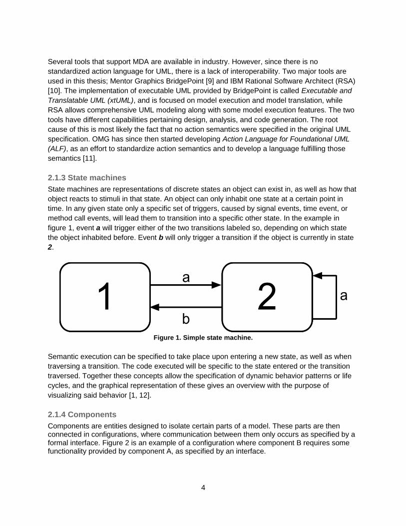
2.1.3 State machines
State machines are representations of discrete states an object can exist in, as well as how that
object reacts to stimuli in that state. An object can only inhabit one state at a certain point in
time. In any given state only a specific set of triggers, caused by signal events, time event, or
method call events, will lead them to transition into a specific other state. In the example in
figure 1, event a will trigger either of the two transitions labeled so, depending on which state
the object inhabited before. Event b will only trigger a transition if the object is currently in state
2.
Figure 1. Simple state machine.
Semantic execution can be specified to take place upon entering a new state, as well as when
traversing a transition. The code executed will be specific to the state entered or the transition
traversed. Together these concepts allow the specification of dynamic behavior patterns or life
cycles, and the graphical representation of these gives an overview with the purpose of
visualizing said behavior [1, 12].
2.1.4 Components
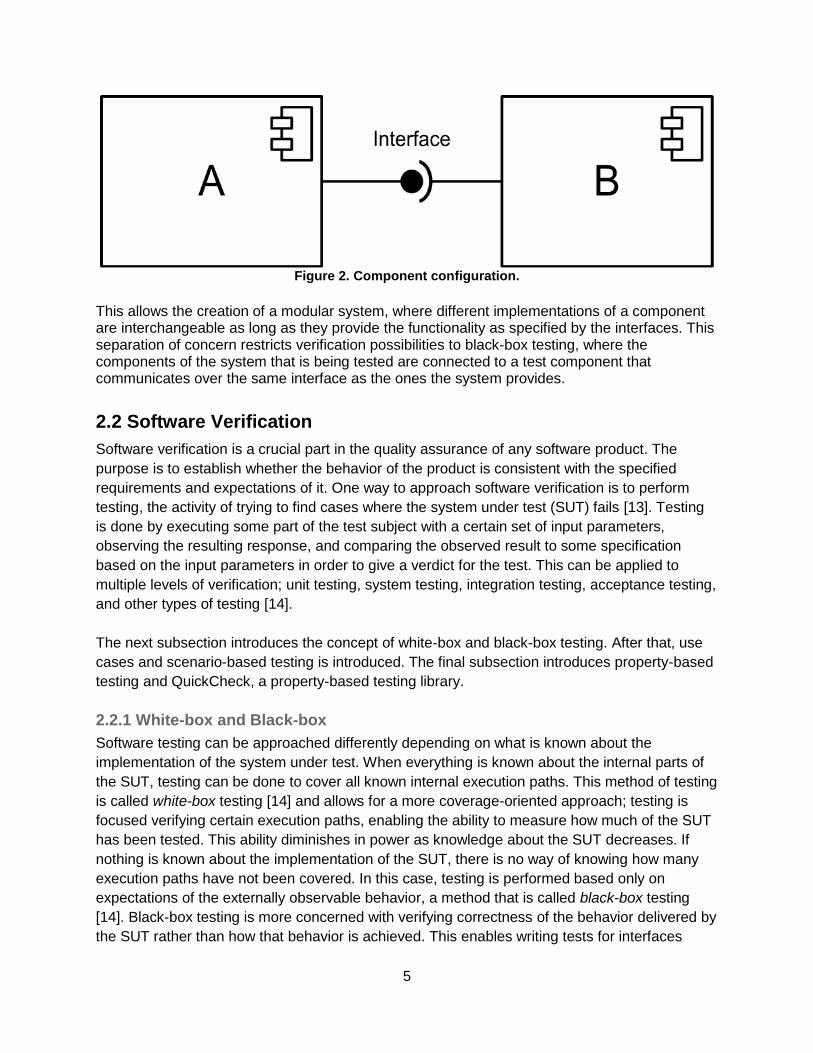
Components are entities designed to isolate certain parts of a model. These parts are then connected in configurations, where communication between them only occurs as specified by a formal interface. Figure 2 is an example of a configuration where component B requires some functionality provided by component A, as specified by an interface.
5
Figure 2. Component configuration.
This allows the creation of a modular system, where different implementations of a component are interchangeable as long as they provide the functionality as specified by the interfaces. This separation of concern restricts verification possibilities to black-box testing, where the components of the system that is being tested are connected to a test component that communicates over the same interface as the ones the system provides.
2.2 Software Verification
Software verification is a crucial part in the quality assurance of any software product. The
purpose is to establish whether the behavior of the product is consistent with the specified
requirements and expectations of it. One way to approach software verification is to perform
testing, the activity of trying to find cases where the system under test (SUT) fails [13]. Testing
is done by executing some part of the test subject with a certain set of input parameters,
observing the resulting response, and comparing the observed result to some specification
based on the input parameters in order to give a verdict for the test. This can be applied to
multiple levels of verification; unit testing, system testing, integration testing, acceptance testing,
and other types of testing [14].
The next subsection introduces the concept of white-box and black-box testing. After that, use
cases and scenario-based testing is introduced. The final subsection introduces property-based
testing and QuickCheck, a property-based testing library.
2.2.1 White-box and Black-box
Software testing can be approached differently depending on what is known about the
implementation of the system under test. When everything is known about the internal parts of
the SUT, testing can be done to cover all known internal execution paths. This method of testing
is called white-box testing [14] and allows for a more coverage-oriented approach; testing is
focused verifying certain execution paths, enabling the ability to measure how much of the SUT
has been tested. This ability diminishes in power as knowledge about the SUT decreases. If
nothing is known about the implementation of the SUT, there is no way of knowing how many
execution paths have not been covered. In this case, testing is performed based only on
expectations of the externally observable behavior, a method that is called black-box testing
[14]. Black-box testing is more concerned with verifying correctness of the behavior delivered by
the SUT rather than how that behavior is achieved. This enables writing tests for interfaces

6
rather than implementations, which in turn promotes encapsulation and distributing development
tasks.
2.2.2 Scenario-based testing
The UML standard defines a technique of specifying behavior in terms of use cases. A use case
is defined as a set of actions performed by a system, which creates an observable result [12].
According to the standard, the full behavior of a system can be described with one or more use
cases based on the requirements of the actors using the system. This principle is often used in
testing. A test case can be built as a scenario, a runnable set of actions representing an
execution of a use case. The use case then describes the expected response of executing the
scenario, and a comparison between expected response and actual response determines
whether the system complies with the specification. This kind of testing can be used to test large
parts of a system. If the scenarios cover all possible responses for every possible stimulus, they
can be seen as a full formal specification of the system behavior. However, it is not feasible to
fully test all systems using scenarios. Some systems have a massive number of execution paths
due to external factors such as randomness, timer values, and user input affecting their
behavior that increases the effort involved with creating scenarios.
2.2.3 Property-based testing
Property-based testing is an approach to testing which, unlike scenarios, does not specify
expected outcome from a specific set of actions. Instead the idea is to describe expected
behavior in the form of properties that should hold for any executions of the system. In practice,
the testing is done by performing a set of executions with different input for each execution,
where an execution fails if the property does not hold throughout the entire execution. Some
promoters of the technique suggest guiding the creation of test cases based on the properties in
order to gain some meaningful coverage [15].
QuickCheck is a testing tool that applies the principles of property-based testing. The tool tries
to alleviate the tedious task of manually creating test cases by generating them randomly [16].
The effort of creating test cases is instead focused on creating test case generators, which can
automatically generate test cases with random input data. QuickCheck provides syntax for
writing properties and invariants which should hold for any input data, using constructs that
resemble formal logic. Logical implications in the properties can be used to filter out irrelevant
test cases. One valuable aspects of QuickCheck testing is the possibility to shrink failing test
cases in order to find the smallest failing test case. This helps debugging and finding the
underlying cause for detected defects.
7
3. Research approach
This thesis is a design research study focused on testing in model-driven software development.
Hevner et al. defines design research as the process of creating artifacts by applying some
design, with the intention of evaluating the utility provided by said design [17]. The artifact under
evaluation in this thesis is a design pattern for writing test models using executable modeling
languages. The design pattern is based on an initial idea from our academic supervisor which
was refined after discussions with our supervisors in both academia and industry.
The design pattern is evaluated by applying it in creating a set of test models which specifies
and verifies the expected behavior of two different systems. While modeling expected behavior
is the main focus of the evaluation, other concepts such as random test case generation and
model transformation are explored as well. Two different modeling tools are used to implement
the test models. The tools provide slightly different modeling capabilities and using them allows
evaluation of the design pattern with regards to the research question.
In alignment with the research guidelines proposed by Hevner et al., each of the
implementations created has a specific purpose where different aspects are focused upon. The
knowledge gained from creating each implementation is applied in subsequent implementations,
thus improving the quality of the process of iteratively applying the pattern under evaluation [17].
The implementations are evaluated using a descriptive evaluation method where informed
arguments are built based on the knowledge gained from developing the artifacts, as well as
knowledge gained from studying related work. The choice of evaluation method is motivated by
a lack of relevant metrics and reference points, and the innovative nature of the suggested
design pattern.
Data contributing to the evaluation of the design pattern include amount of effort involved in
applying the pattern when implementing test models, how understandable the resulting test
models are, whether bugs are actually found in the tested systems, and observations about how
well the pattern can be implemented in different tools. This data is then interpreted to assess
and draw conclusions about different aspects of the design pattern.
While the implementations are a product of using the suggested design pattern, they are not a
deliverable relevant to the scientific contribution of this thesis. It is rather the pattern itself and
the evaluation thereof which provides new advancements in the field of software verification and
executable software modeling.

8
4. Theory This chapter presents the ideas and suggested patterns that guide the research in this thesis. The first subsection presents a design pattern for how the test environment should be modeled. Secondly, the concept of writing platform-independent behavior specifications where model transformation is used to enable verification on multiple abstraction levels is introduced. In the final subsection, an idea about how externally observable behavior on interfaces can be described and tested using certain patterns in executable state machines is presented.
4.1 Test Environment
The system under test is defined as a component with an interface on which its behavior is specified. In order to test that behavior, the test model is also componentized. In test execution, the test model is connected to the system component in a test configuration (figure 3).
Figure 3. Test configuration.
While running tests can be done by manually executing test case state machines, there is an interest in automating the process. In particular, running multiple test case executions consecutively is of great importance in order to increase the coverage gained by random test case generation. In order to achieve this, test models are developed with the following distinct separation:
● A test engine class initiates the test environment, starts and stops test cases, and keeps track of the amount of test cases to be run.
● The state machine of a test case class represents the execution of one test case. This includes both generating interactions with the SUT, and the validation of those interactions when they are performed.
Figure 4. State machine for test engine class.

9
Figure 4 shows a generic state machine for a test engine. When started, the state machine stays in an initial state until the user triggers the setup transition with some input parameters. In the setup state, variables such as amount of test cases to execute are set. The setup state also makes sure that random generators are properly initiated. When the user triggers the next transition, the test case execution commences. For as long as the number of test cases to be executed has not yet been reached, the state machine cycles between starting a new test case execution and waiting for that execution to complete. When a test case run is complete, it sends a signal to the test engine reporting on the verdict of the test case. This information is stored in the test engine. When all test cases have been executed, the test engine prints out a brief report about the test results as well as the execution paths of the failing test cases. Finally, the test engine transitions back to the initial state awaiting new setup parameters.
4.2 Verification on multiple abstraction levels
The suggested framework is intended to be usable on any interface which provides some behavior or functionality. The system platform is not meant to be a limiting factor. With the flexibility gained from model transformation, test models can be developed at high abstraction levels and then be transformed to any abstraction level with the appropriate translation. This suggests that any system can be tested, no matter if it is a system under development or a system that is already deployed.
Figure 5. Testing on multiple abstraction levels.
Figure 5 visualizes the suggested process of testing on multiple abstraction levels. Testing can be performed with models by expressing them in an executable modeling language, which means designs can be verified before any implementation exists. When the system eventually is

10
transformed into an implementation, so is the test model. This means that tests can be executed again, where the results of the tests should be consistent with the results at modeling level. It is suggested that an inconsistency in test results between the different abstraction levels may be an indicator of an error in the model translation, or that some platform-specific aspect has been neglected when designing system models and test models.
4.3 Modeling Expected Behavior
This is the main concept which this thesis is founded upon. The concept is that expected
behavior can be modeled as an executable state machine which is driven by interactions with a
system under test (SUT). The suggested pattern is a continuous sequence of generating input
for the SUT and then validating how the SUT reacts. If full or partial behavior of a system can be
modeled using this pattern, then that model will be an executable specification which can be
used to test the system.
Figure 6. Generate-validate pattern.
Figure 6 shows the general pattern for modeling expected behavior as a state machine. An
execution begins at an initial state, which represents the expected state of the SUT before any
interaction has occurred. When the execution is triggered, the state machine transitions to a
generate state, which generates and triggers an interaction with the SUT. The possible system
responses, labeled R1 through Rn in figure 6, causes the test model state machine to transition
into a specific for that response. If no response is received within a reasonable time, a timeout
event is triggered and the state machine transitions to another validation state. When validation
is done, the test case either fails, passes, or is continued to another generation state. That may
include a transition back to the generation state that was just performed, resulting in a graph
over expected behavior.

11
Names of states in the suggested state machine approach are meant to follow a certain naming
convention. Consistent naming of states with a certain function, such as generation and
validation, causes a pattern to emerge in the suggested modeling approach that increases
readability and acts as a guideline in how to develop the test models.
Randomness is used to determine what SUT interaction is generated in generation states. While the structure of the suggested approach is similar to scenario-based testing which strives towards a set of specific goals, cyclic execution paths may exist in the suggested modeling approach of a generate-validate graph. Each individual execution path of the graph represents a different scenario, which is visualized by figure 7 where two of the execution paths are highlighted. When there is feedback in the graph the amount of execution paths increases. By automatically traversing the graph using through random execution paths, the effort of manually choosing execution paths is removed. The randomness allows the same test model to be run multiple times without extra effort, while increasing test coverage for every execution.
Figure 7. Abstract representation of a generate-validate graph.
In addition to using randomness to choose what interaction is performed, it is also used to choose how that interaction is performed. Arguments for interaction parameters may affect the expected SUT response; bad input data may result in an error sent as response, argument values within certain boundaries may cause certain responses, and other features might be affected. Randomly generating values for arguments increases the coverage of the SUT behavior. In stateful systems, there is an aspect of persistent memory which affects system behavior. This must be taken into consideration when testing the system, as the expectations are dependent on the system state. In the suggested pattern, this is dealt with in two ways. Firstly, every generation state in the test case state machine represents an externally observable state of the system under test. Every generation state specifies what interactions are expected to be valid at that time. Secondly, some data is remembered by storing it as records in a database which is not visible in the state machine diagram. That data is part of the expected state of the system under test, but is not feasible to be displayed as a separate state in the test case state machine diagram. This is due to the fact that the data may be of a data type with a really large amount of
12
possible values, which would cause the amount of states in the test case state machine to escalate to unfeasibly high levels.
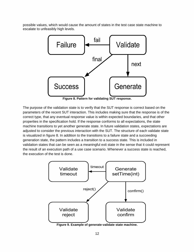
Figure 8. Pattern for validating SUT response.
The purpose of the validation state is to verify that the SUT response is correct based on the
parameters of the recent SUT interaction. This includes making sure that the response is of the
correct type, that any eventual response value is within expected boundaries, and that other
properties in the specification hold. If the response conforms to all expectations, the state
machine transitions to yet another generate state. In future validation states, expectations are
adjusted to consider the previous interaction with the SUT. The structure of each validate state
is visualized in figure 8. In addition to the transitions to a failure state and a succeeding
generation state, the pattern includes a transition to a success state. This is included in
validation states that can be seen as a meaningful exit state in the sense that it could represent
the result of an execution path of a use case scenario. Whenever a success state is reached,
the execution of the test is done.
Figure 9. Example of generate-validate state machine.

13
The functionality of generate- and validate states is implemented using action languages. As an example, consider the action of setting cooking time on a microwave oven. The expected response of that action depends on the value set as cooking time; negative time is not allowed, and there might be an upper limit as well. If setting the time was the only valid action, the test state machine would look as shown in figure 9. The generate state would create a random value for the input parameter, store a record of that parameter value, and perform the action with the system under test. When a reject of confirmation is received as response from the system, a validation is done using action code. The pseudo-code in figure 10 shows the semantics of how this validation can be implemented when receiving a confirmation on cooking time being successfully set, which would be located in the ‘Validate confirm’ state. Similar code would be in the other validation states, adjusted to validate the received response.
IF input time value was within legal range THEN confirmation was expected, proceed with test case ELSE confirmation was not expected, test case fails! END IF
Figure 10. Pseudo-code for validating confirmation of setting time.
The pattern of generating and validating system interactions is used as building blocks, chained together forming a directed graph that describes full or partial expected behavior of the SUT. One factor in deciding whether full or partial behavior should be modeled is if there is an interest to test for robustness. If there is, then a more complex model is required to specify how the system should handle unexpected input in addition to input that contributes directly towards a specific goal. It is then also important to consider the fact that the lack of response on an interaction is itself a result of the interaction; not receiving any response within a certain time may be correct in some cases, and must be validated as such.

14
5. Evaluation Setup
This chapter describes how the implementations using the proposed design pattern are created. First to be presented in this chapter is the systems whose behaviors are tested by the implemented test models. In the second subsection, the operation details and goals for the different implementations are described.
5.1 Systems under test
The evaluations are focused on empirically evaluating theories for developing test models with concern to a particular modeling pattern. The test models are designed to verify the behavior of some functionality as specified by an interface. Since interfaces do not reveal anything about how the specified functionality is achieved, only externally observable behavior can be verified. The functionality specified by an interface can vary greatly in complexity, and two different systems are tested in this evaluation.
5.1.1 Microwave Oven
The first system to be tested is a microwave oven. Originating in the tutorial of the xtUML tool BridgePoint, it has been used in previous studies with the focus of software testing. This was a major factor in the decision to use the microwave oven, since it allows the proposed pattern to be compared with other approaches to testing in model-driven development. The behavior of the model found in the BridgePoint tutorial is shown in figure 11. It was originally a self-contained model where user interactions were modeled as action code operations.
Figure 11. State machine for a microwave oven.

15
The state machine does not only visually present an abstract representation of how the system
works, but also provides semantics for the behavior through the use of xtUML action code. The
code snippet shown in figure 12 is an example of how the control flow through the state
machine is affected by values of attributes on the microwave oven. The code snippet
implements the feature that cooking may not begin if the door is not closed, or if the remaining
cooking time is below zero.
if (self.remaining_cooking_time > 0)
if (self.is_secure == true)
generate MO_O7:'oven_safe'() to self;
end if;
end if;
Figure 12. Action code in "Ensuring Safe to Cook" state.
Since the model that was available in the BridgePoint tutorial did not accept user interactions
through interfaces, it had to be adjusted for that purpose. Transitions that were previously
triggered by operations or internal events are now triggered externally through a signal sent on
an interface. The system is also redesigned to send a response and indicate whether a
requested action was performed successfully. After the adjustments were done, the system is
seen as a black-box component with its externally observable behavior specified through an
interface (see figure 13).
Figure 13. User interface of microwave oven component.
5.1.2 Simple server application
The second system to be tested is an implementation of a simple server application. In difference from the microwave oven system, there was no previous implementation of this system. The reason why this system is tested is rather that the precursor of its behavioral interface is used in a tutorial where QuickCheck is used to test stateful systems [18]. The interface (figure 14) is very simplistic and provides asynchronous signals for registration and unregistration of string values, as well as signals representing the possible response for both operations. A desired property in the server is that no duplicates of any registered string values are allowed, which is the main feature to be tested later on during evaluation.

16
Figure 14. Interface provided by the server
The effort involved in developing this system was minimal, without the intention of creating a completely flawless system. On the contrary, it is assumed that the implementation is flawed when performing testing, as to evaluate how effective the testing approaches are in finding flaws.
5.2 Implementations
This section describes how the four different experimental implementations are planned to be performed, and what aspects are evaluated in each implementation. Setup and general approach are discussed, whereas the results of the implementations are reported in the next chapter.
5.2.1 Implementation 1: Testing Microwave Oven in BridgePoint
The microwave oven model is the system under test in this implementation, which is developed
in BridgePoint. This is the implementation with most direct associations to the theories of using
a generate-validate sequence to describe system behavior. The modeling approach used is
very inspired by use cases; only testing specific sets of actions where each set of action leads
to an observable result [12]. Random generation of signals is implemented, although restricted
to only generating valid signals based on knowledge about the current state of the SUT.
Robustness is not tested in this implementation. Included in the work of this implementation is
also a transformation from executable models to source code using a proprietary model
compiler developed at Ericsson.
This implementation is done to analyse the implications of using the suggested design pattern
when black-box testing an interface. In particular, there is a concern of identifying the
constraints that need to be applying to the tested system when performing testing as a
sequence of generating and validating input. The source code generation is done to provide
some insight in the possibilities of verifying model transformation consistency, as well as to
investigate the possible advantages of gained performance by test execution on other platforms.
5.2.2 Implementation 2: QuickCheck-inspired testing of server application
In this implementation a test model is developed for the server application described in 5.1.2.
The model is developed in BridgePoint, and focuses on describing expected behavior textually
using action language. The modeling approach is inspired by a tutorial of how QuickCheck can

17
be used to test stateful systems, where randomness is used to generate interaction sequences
that are later performed against the SUT and the SUT responses are validated. As details about
behavior and validation are described more textually, the structure of the graphical state
machine deviates somewhat from the suggested pattern.
This implementation is done to allow comparison between graphical and textual representations
of expected behavior in software modeling. The difference in model complexity in the test model
is analysed with regards to advantages and disadvantages of both techniques, in particular how
history about previously generated input for the system affects the expected system state.
5.2.3 Implementation 3: QuickCheck-inspired testing of Microwave Oven
This is the second implementation where the microwave oven is under test. The experiences
and insights from developing the two first implementations are incorporated in the development
of this third implementation. Robustness testing [14] is done, which means the expected
behavior is more exhaustively specified to include exceptional behavior and handling faulty
input. The implementation is developed in BridgePoint. A more textual approach is used in
describing expected behavior than what is done in the first implementation. This inherently
means that certain aspects of the expected behavior are not made visible in any diagram.
This implementation is done to explore the trade-off between expressiveness and readability in
system models that emerges when part of the expected system state is modeled textually rather
than graphically. Since this implementation models expected behavior more exhaustively to
include robustness testing, additional observations are to be made about necessary constraints
on the system under test.
5.2.4 Implementation 4: Testing Microwave Oven in IBM RSA
This implementation differs from the other implementations in the sense that another modeling tool is used to develop it. IBM Rational Software Architect is used, and the microwave oven is the system under test. Since it is not possible to directly import BridgePoint-developed models into RSA, a new model based on the existing model of a microwave oven is implemented in RSA, in addition to the test model. With the exception of tool used, this implementation is very similar to the first implementation pertaining modeling techniques used. However, this implementation does not include the model transformation that is done in the first implementation. This implementation is done to identify what activities of the proposed design pattern must be
adapted for the chosen modeling tool, and how they need to be adapted. Deviations in
expressiveness of action languages and how models are created in different tools affect not
only how systems are modeled, but also how tests are modeled.
18
6. Evaluation Results This chapter presents the results for each of the implementations that were introduced in the previous chapter. In each of the following subsections, the development process and implementations are described. Additionally, observations made throughout the development are presented and interpreted.
6.1 Results: Testing Microwave Oven in BridgePoint
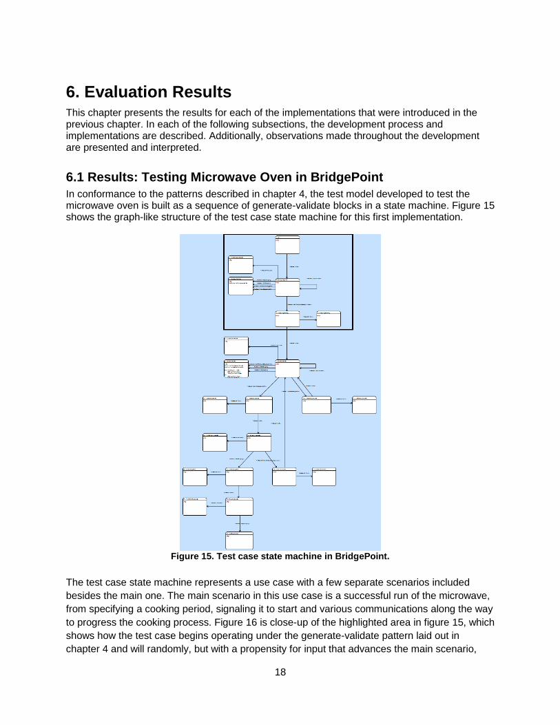
In conformance to the patterns described in chapter 4, the test model developed to test the microwave oven is built as a sequence of generate-validate blocks in a state machine. Figure 15 shows the graph-like structure of the test case state machine for this first implementation.
Figure 15. Test case state machine in BridgePoint.
The test case state machine represents a use case with a few separate scenarios included
besides the main one. The main scenario in this use case is a successful run of the microwave,
from specifying a cooking period, signaling it to start and various communications along the way
to progress the cooking process. Figure 16 is close-up of the highlighted area in figure 15, which
shows how the test case begins operating under the generate-validate pattern laid out in
chapter 4 and will randomly, but with a propensity for input that advances the main scenario,

19
generate a signal to send to the microwave oven. The response (or lack thereof) is validated,
causing the test case to proceed in an appropriate manner.
In several instances throughout the test case, there are system responses that are not relevant
in the part of the behavior that is specified. As seen in figure 16, the signals which are not
relevant are bundled together to eliminate the need for validating them individually.
As a way of detecting if no response is received, timers are started. The timers generate timeout
events after a certain amount of time, indicating that no response was received. Additionally, a
second timer with shorter timeout value is started representing a performance requirement;
expectations on how fast a response should be received. If the response does not match
expectations, the test case is considered to have failed and stops its execution. If the response
was expected, i.e. the system conforms to the specified expectations, the test case would
progress to the next sequence of generate- and validate states until reaching either any of the
states representing an unsuccessful run or the ending successful run.
Figure 16. Implementation of generate-validate pattern.
Initially, because of the way signals are handled in BridgePoint, a filter was created to allow grouping of multiple signals together in several different configurations. This to allow handling several input signals, which should trigger the same response, in one transition in the test case. This to reduce clutter and redundancy in said test case. While the filter did achieve those purposes, the filter rapidly grew very complex and less readable at only a small amount of signals (see figure 17). Mapping it for the entire microwave system, let alone a large-scale system would be unfeasible. Thus alternate solutions were

20
adopted where the reception of signals directly in the interface would propagate to the correct instance state machines, leading to the abandonment of the idea of a unifying filter.
Figure 17. Filter state machine.
As BridgePoint has no innate random number generator, a linear congruential generator
providing random number generation previously developed at Ericsson Baseband Research
was used. This was necessary to allow random inputs into the test case in order to run
exhaustive tests. The random number generator is implemented as a class within the test
component.
When the models were finished and evaluated, they were translated into C source code using a
proprietary xtUML-to-C model compiler for BridgePoint developed at Ericsson. The system was
then run using these translated C programs. As the tests again pass, or fail, this is also proof of
the translation architecture being correct. Running the C programs the amount of tests run could
also be increased to much larger amounts as the faster execution rate of C allows much more
tests in the same timeframe. This has implications for test coverage of the system, as the tests
can be allowed to cover more of the possible execution paths in the system. The real time
aspect of the translation proved to be complicating the execution of the tests at source code
level. Execution of C code was fast enough to make the delays caused by timer objects such as
when waiting a specific time for the microwave oven to finish cooking greater than the entirety of
the rest of the test. This is the result of the microwave using time as defined by the timers in
BridgePoint rather than time as an abstract concept.
Contribution to research questions
How can a general design pattern be produced for building executable black-box test models using a general-purpose modeling language, with regards to: c. Constraints put on the system under test?

21
The observations made during the development of this implementation highlighted the need of consistency in how the system communicates through its interface when building a test model which uses that interface. In some cases it was not clear how the system had reacted to stimuli, due to a lack of appropriate response. d. Ability to apply the pattern for testing at different abstraction levels? Regarding the question of testing at different abstraction levels, the transformation of the test and system models into source code showed the possibility of having components tested at several levels of abstraction. The only issue found was related to differences in how time is expressed at the model level compared to the source code level.
6.2 Results: QuickCheck-inspired testing of server application
The state machine for the test case class is shown in figure 18 below. When the test case
execution starts, the first action that occurs is the generation of SUT interactions. Much like how
the QuickCheck library for testing stateful systems works, this is done by generating a sequence
of randomly chosen symbolic interactions. This means that while the semantics of the
interactions are generated, they are not actually performed. Since the generated interactions
are completely random, we do not care about achieving a particular goal or fulfilling a use case
but rather testing that the SUT responds as expected no matter what interactions are
performed. Therefore, the length of the interaction sequence is randomly selected rather than
being stopped when a certain state is expected to be reached. The probability of the sequence
to be ended is fairly low after each generated interaction in order to create a sufficiently long
sequence.
Figure 18. State machine diagram representing a test case.

22
When a full sequence of SUT interactions has been generated, the test execution begins. One
by one, the symbolic interactions in the sequence executed and the system response is
validated. When the next interaction to be performed is identified, the test case state machine
transitions into a state representing that specific interaction. That state describes how that
specific interaction should be validated. The test case class maintains a record of what state the
SUT is expected to be in after each interaction. This record is used to calculate the expected
response for each interaction before it is performed. When the interaction is performed the state
machine transitions triggered by the SUT response, where the actual response is validated
against the expected response, and the record of expected SUT state is updated.
Interactions with the SUT may include parameters, which are randomized as well. However,
there were some difficulties in generating parameters that were not numerical. There are no
built-in helper functions that allow advanced manipulation of the default data types in
BridgePoint. The only built-in function for the string data type is concatenation which is
expressed with the plus (+) operator. This meant that random string generation had to be
implemented in the action language used in BridgePoint, using the random number generator
described in the first implementation, which in this implementation has been extracted into a
separate component. The implementation in this system is limited to generating strings with a
given length that may contain only a small subset of the alphabet, in order to generate
duplicates within a reasonable amount of generated interactions. This constraint implies smaller
entropy in test cases generated, but more relevant test cases are generated.
The record of expected SUT state is not stored as a graphical state machine, even though the
SUT is a stateful system. Since the parameters to the generated interactions include string
values, we need to store these values as part of the expected SUT state. This is done by
creating instances of a class which has attributes describing what values are expected in the
SUT, similar to rows in a table. The pseudo-code in figure 19 shows how this representation of
expected state is used in validation of receiving confirmation on registering a value on the
server; if that value has not been registered already, it is expected to be accepted by the server.
SELECT all entries FROM the table of expected entries in the server
WHERE value == the value that was just attempted to be registered
IF no such entries could be found
THEN confirm was expected, test succeeds
ELSE confirm was not expected due to existing duplicate, test fails
END IF
Figure 19. Pseudo-code for validation of registering value on server.
Contribution to research questions
How can a general design pattern be produced for building executable black-box test models using a general-purpose modeling language, with regards to: a. Tool independence?

23
The need for random string generators highlighted a case where additional efforts needed to be done in order for the pattern to be applicable in BridgePoint. b. Mode of expression in implementation of the test model? The observations made in developing this implementation show that expected behavior can be
expressed using textual notation in addition to graphical notation, while still applying the
underlying pattern.
6.3 Results: QuickCheck-inspired testing of Microwave Oven
This implementation applies the modeling approach used in the second implementation, where expected state is described with an increased use of action language and decreased use of graphical diagrams, for testing the microwave oven.
Figure 20. State machine for the test engine class.
The test engine in this implementation has been extended slightly to implement a shrinking
algorithm. This is done in the test engine rather than in the test case itself, to maintain a
modular design where the test engine can be reused with other test cases. Figure 20 above
shows the visual impact on the state machine which has two additional states compared to the
versions in the other experimental implementations.
One of the purposes of this implementation was to further examine the implications of
describing expected SUT behavior textually rather than graphically. This is realized by
representing externally visible SUT states using an enumeration data type in BridgePoint, a data
type which consists of a finite amount of enumerators that may be used as value for an attribute
of the data type. Describing the externally observable SUT states in this way enables calculating
expected behavior and other aspects that are state-dependent textually.

24
Figure 21. State machine for the test case class.
The generation of SUT interactions is performed in advance, creating a sequence of symbolic SUT interactions. The main difference compared to how the generation is done in the second implementation is that in this case, we are interested in making the SUT reach a certain state. This is achieved by symbolically executing the interactions as the sequence is being generated, which enables checking what state the SUT is expected to be in after a certain sequence of interactions. The sequence is extended as long as the desired state has not yet been reached in the symbolic execution. In practice this means that interaction sequences can become very large based on the random factor, which in turn increases the probability of find errors that occur when partial execution paths are executed several times consecutively. Just as in the second implementation, the sequence of interactions is performed and validated when the generation is done. In this implementation, there is a single state that sets expected response, performs the interaction, and updates the expected SUT state. Any SUT response will trigger a transition from that state, where expected response and actual response are compared to verify that the correct response was received. The distinction between how different types of interactions are validated is done in action code operations rather than by traversing different states in a graphical state machine. An effect of this is that the test case state machine diagram has a reduction in amount of states which is visualized by figure 21, whereas a lot of the state space is hidden in action code. The test case state machine is designed to allow the execution of predefined interaction
sequences, which can be created in the test engine class. This enables performing shrinking on
an interaction sequence that causes the test case to fail; an algorithm is used to systematically
rerun the test case with smaller and smaller subsets of the failing interaction sequence. If an

25
interaction is removed from the failing interaction sequence and the failure remains, it means
that interaction is not part of the critical failure sequence. This is repeated until the resulting
sequence only contains interactions that contribute to the failure. The resulting sequence should
then give more concise clues to the underlying cause of the failure. Such an algorithm is
included in this implementation (see figure 22). However, the implementation is very inefficient
which makes the shrinking process take a lot of time when performed in the model execution
environment of BridgePoint which makes it less viable as part of a desired testing process.
Using a more efficient shrinking algorithm would increase the performance of re-running test
cases to minimize a failing test case.
FOR EACH interaction IN failing interaction sequence remove current interaction from failing interaction sequence re-run test case with new interaction sequence IF test case still fails THEN the removed interaction is not part of critical path ELSE the removed interaction is added to the sequence again END IF END FOR resulting sequence is the smallest failing sequence
Figure 22. Pseudo-code for rudimentary shrinking algorithm.
During the development of this implementation, a previously undetected bug was found in the microwave oven. The bug caused an error when the door of the microwave oven was opened and closed repeatedly in some particular circumstances. The cause of the problem was unwittingly introduced when the microwave oven model was adapted to handle communication through interfaces. As the test model was still in development, it was not obvious that the failing test case actually reflected an error in the SUT. Our first instinct was rather that there was something wrong in the specification; the operations that describe expected behavior textually.
Contribution to research questions
How can a general design pattern be produced for building executable black-box test models using a general-purpose modeling language, with regards to: b. Mode of expression in implementation of the test model? In this implementation it is shown that while the suggested pattern may be successfully implemented using primarily action code with less of the state space in graphical state machine, the expressive power of the action language is gained at the cost of decreased visualization of expected behavior.
26
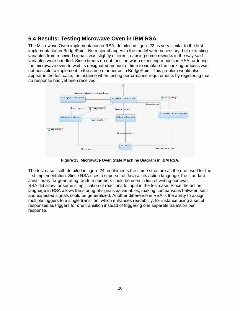
6.4 Results: Testing Microwave Oven in IBM RSA
The Microwave Oven implementation in RSA, detailed in figure 23, is very similar to the first implementation in BridgePoint. No major changes to the model were necessary, but extracting variables from received signals was slightly different, causing some reworks in the way said variables were handled. Since timers do not function when executing models in RSA, ordering the microwave oven to wait its designated amount of time to simulate the cooking process was not possible to implement in the same manner as in BridgePoint. This problem would also appear in the test case, for instance when testing performance requirements by registering that no response has yet been received.
Figure 23. Microwave Oven State Machine Diagram in IBM RSA.
The test case itself, detailed in figure 24, implements the same structure as the one used for the first implementation. Since RSA uses a superset of Java as its action language, the standard Java library for generating random numbers could be used in lieu of writing our own. RSA did allow for some simplification of reactions to input in the test case. Since the action language in RSA allows the storing of signals as variables, making comparisons between sent and expected signals could be generalized. Another difference in RSA is the ability to assign multiple triggers to a single transition, which enhances readability, for instance using a set of responses as triggers for one transition instead of triggering one separate transition per response.

27
Figure 24. Test case state machine in IBM RSA.
Differences in the way communication works in RSA meant that the communication between
components had to be redesigned. RSA does not support action code being specified to
execute on signal reception in the signals themselves, meaning that dispatchers resembling the
filter class from the first implementation had to be implemented here as well, with the same
drawbacks. Furthermore, this also had to be applied when sending signals from a component,
so achieving a separation of concern by dividing the tests from the system in separate UML
components remains unfeasible without first developing some way of simplifying
communication.
RSA supports translation of structural elements into a range of languages, but the same is currently not true for action code describing dynamic behavior. Thus, the complete translation of platform independent models along with their semantic behavior into platform specific executable source code is a functionality not found in RSA.

28
Contribution to research questions
How can a general design pattern be produced for building executable black-box test models using a general-purpose modeling language, with regards to: a. Tool independence? The results of this implementation show that the pattern presented in the thesis require further development to achieve tool independence. The necessity for a modeled abstract time concept became apparent. Component communication also remains an issue that would require further development.

29
7. Discussion This chapter presents and elaborates on several topics of discussion that emerged from the results of developing implementations of the theories under evaluation.
Hidden state
As work with the different implementations progressed, it was apparent that the modeling approach used had an impact on benefits gained from abstractly modeling expected behavior. Graphical representations of expected behavior give an overview which seems more intuitive to understand in comparison to textual specifications. As the behavior under test is affected by an increasing amount of variables, the state space needed to represent it increases exponentially. This phenomenon is widely known as the state explosion problem [19]. This suggests that a graphical representation of expected behavior might become cluttered and less readable for more complex behaviors. The state explosion problem persists even when behavior is modeled textually using action language, but then some states might be simplified using formal expressions or by storing a state as the value of an attribute. This is an example of a technique for mitigating the state space problem which suggests grouping states together for a reduced state space size [20, 21]. However, textual representations do not contribute to the aspect of visibility that is gained by graphical representation. There is a trade-off between expressiveness and visibility that guides the decision on how to model expected behavior, and there is an incentive to distinguish parts of the expected behavior where visibility is valuable from what can be hidden in textual representation. This shows how the complexity and capabilities of general-purpose modeling languages can help establish an appropriate abstraction level, which has been expressed as a challenge in the research field of model-driven development [5].
Distribution of Randomness
The state explosion problem is also relevant in the use of randomly selecting execution paths.
Since the amount of test cases needed to reach a certain coverage increases with the state
space, it makes sense to distribute the random selection of execution paths with some goal in
mind. Case in point; figure 25 on the next page shows a state machine where if the choice of
transitions is normally distributed, the probability of reaching a final state decreases with the
graph depth.

30
Figure 25. Graph where final states are at different depths.
If the choice of transition is instead balanced according to how the final states of the graph are distributed, the probability of generating redundant test cases is lower. When part of the state is hidden outside the state machine as suggested in the pattern under evaluation in this thesis, each state in the modeled state machine represents a larger state space than what is visible. This must also be taken into account when determining how randomness should be distributed.
Differences in modeling tools
While the possibilities of platform independence in structural and behavioral modeling are apparent in both BridgePoint and IBM RSA, there are differences in the utility provided by the two tools. When trying to implement the same model in both tools, we noticed that the model developed for the first tool was incompatible on an abstract level to how the other tool described the same functionality despite the fact that both of the tools allow platform-independent modeling. Timing is described differently in the two tools, and one of the tools does not consider timers when executing the models. Our models were implemented with one of the tools in mind and we had not considered timing to be an issue in the other tool. This illustrates that a lot of effort needs to be put into establishing a suitable abstraction level when proposing a design approach that is meant to be independent of tool used. On the other hand, some aspects may be modeled with less effort by using libraries provided by a certain tool. Case in point; IBM RSA allows using the Java libraries as the action language is a superset of Java. This allowed us to easily implement random test case generation using the standard Java random library, while no such native library existed in BridgePoint. Other features such as string manipulation were also easier with the standard Java libraries. This observation suggests that there is a trade-off between utility gained and tool independence. While the significance of tools in model-driven development has been identified previously [5], this also suggests that the differences in provided functionality affect how design patterns may be applied.
31
It should be noted that while we were unable to implement some aspects of the suggested pattern in RSA, it is possible that someone with higher tool knowledge would be able to. It is possible that the initial idea for the suggested pattern was created with BridgePoint in mind, and could have been designed differently by someone with more experience in RSA.
Who watches the watchmen?
An inherent problem in software verification is the fact that errors may occur in the testing process itself. This phenomenon is commonly phrased as “Who watches the watchmen?”. Even during the development of the implementations in this thesis, this problem was apparent. When a defect was found, we could not be sure whether the error was in the system under test or in the test model. Techniques for the dealing with the watchmen problem exist [22], but they require access to the implementation of the system under test which is not possible in a black-box setting. Determining if a detected failure has its source in the test or in the system under consideration is instead based solely on correctness of the specification in the test model. In our work, we were able to find the source of the error faster in the implementations with expected behavior modeled graphically than in the ones modeled using action language. This suggests that the overview gained by graphical modeling in a certain design pattern affects the assumption of where bugs are to be found when an error is detected, as it shows intuitively what state the system under test is in when the error is found. The most effective method of locating errors is through mental analysis [13], which strengthens the suggestion that intuitive graphical overviews help finding error sources.

32
8. Related work Another example of testing done to aid Model-Driven Development is the work of the Finnish
company Conformiq with their QML language and Qtronic editor [23], which are currently being
evaluated at Ericsson for potential use. It allows you to specify a model, either textually via a
superset of Java, or via graphical state machine models which are a subset of UML.
QML is designed for Model-Based Testing [24] which is an alternative to Model-Driven Testing,
where the system model that is to be tested is also used as a source for generating test cases
by applying a graph solving algorithm. These test cases are then implemented separately as
part of the development process itself, and adjustments to the system model which is to be the
basis for implementation later are introduced to ensure it passes the expectations of the
customer. This in contrast to Model-Driven Development, where the ambition is to develop the
system as models all the way to the end through translations into code, and even test cases are
described as executable models. Compared to QML, the theories evaluated in this thesis
provide a way of testing software models on a high level of abstraction which removes the extra
effort of implementing the generated test cases in a platform-specific language.
Related work has been done at Åbo University in collaboration with Ericsson [25] showing that it is possible to transform models from UML to QML by extracting UML models into an XMI format, and then creating the QML model from these XMI files. This allows for using the benefits of the automatic test case generation in QML despite the project having its basis in UML, and still continuing with Model Driven Development. A study at Mälardalen University [26], also in collaboration with Ericsson, demonstrated the
transformation of xtUML models using BridgePoint’s own translation engine into QML. This work
also used the basic example of a microwave oven as a simple model which served as the basis
for reasoning about larger projects.
Yet another collaboration between Ericsson and Mälardalen University [27] explored the subject of automatically generating test cases in TTCN-3, which is a well proliferated scripting language for testing [28]. BridgePoint xtUML projects with class or sequence diagrams were extracted into an XMI-file format. These XMI files are used to generate a graph, and with this graph acting as a representation of the system, TTCN-3 test cases are generated.
While the three studies just presented allow for generation of meaningful test cases from the SUT, it adds more effort in transforming the models between the different platforms. The suggested approaches in this thesis improve how test cases are modeled, which is a step towards reducing this need for additional tools in order to perform testing on models. Additionally, as discussed in chapter 7, the ability to model the tests before or during the system is being modeled gives further advantages to the suggested approaches.
An article discussing the testing of stateful systems has been written at Chalmers University of
Technology [18], which centered around the use of QuickCheck to perform these tests. The use
of QuickCheck instead means that rather than scenarios and use cases being the foundation for

33
an executable model, preconditions and postconditions that should hold are specified
separately, and large amounts of input is randomized into the system. When these principles
were evaluated in this thesis, there was a difficulty in creating pre- and postconditions as
separate properties due to how asynchronous communication is handled in the modeling tools.
Where a QuickCheck property describes how the response to an operation should look formally
with a textual syntax, the same property might have to be described using multiple states in a
state machine diagram. This suggests that there is a trade-off between readability and
expressiveness. The article also describes how QuickCheck provides efficient shrinking of
failing test cases. While being nowhere as efficient, an implementation of shrinking has been
done during this thesis, showing that the functionality is possible to achieve in xtUML as well.
A thesis at Chalmers University of Technology [29] explored the possibilities of modeling a component in IBM RoseRT, translate these to C++ source code and test them using QuickCheck. This approach, which more closely resembles traditional testing, places the tests at a lower abstraction level than that of the model. While the ability to write tests before or during the development of the model is possible with this approach, the ability to test at the model level is lost compared to the methods laid out in this thesis.

34
9. Conclusions and Future Work
The proposed pattern for describing and verifying expected behavior was successfully implemented in both Mentor Graphics BridgePoint and IBM Rational Software Architect, but minor adjustments were made in order to conform to differences in how the tools handled communication. This and other minor tool differences highlighted a need of identifying all tool specific aspects when creating implementations using a design pattern meant for any general-purpose modeling language. A constraint that must apply when using the pattern is that the system under consideration should give an observable response to each stimuli, and if no response is given there must be no ambiguity to what that means. The results of running the tests at both model- and code level through model transformation show the need of correctly modeling platform-specific aspects both in system- and test models. The suggested patterns have only been evaluated for testing small-scale systems, and future work in the field may be directed at evaluating the potential of using the patterns for testing larger systems, as there is an interest in exploring how the expressiveness is affected as the complexity of tested behavior grows. Another possible direction for future work is to research how the shrinking algorithm can be improved in order to more efficiently reduce the size of failing test cases, to make it more viable as a recurring activity in the process of testing using executable models.

35
10. References 1. Mellor, S.J., M. Balcer, and I. Foreword By-Jacobson, Executable UML: A foundation for
model-driven architectures. 2002: Addison-Wesley Longman Publishing Co., Inc. 2. OMG Mission Statement, OMG:
http://www.omg.org/gettingstarted/gettingstartedindex.htm. 3. Cavarra, A., THE UML TESTING PROFILE. 4. Maunumaa, M. and M. Katara. Modeling concern-based testing with UML testing profile.
2011. 5. France, R. and B. Rumpe. Model-driven development of complex software: A research
roadmap. 2007: IEEE Computer Society. 6. Cuong, N.V. and X. Qafmolla, Model transformation in web engineering and automated
model driven development. International Journal of Modeling and Optimization, 2011. 1(1): p. 7-12.
7. Kit, E. and S. Finzi, Software testing in the real world: improving the process. 1995: ACM Press/Addison-Wesley Publishing Co.
8. Nguyen, D., A. Perini, and P. Tonella, A goal-oriented software testing methodology. Agent-Oriented Software Engineering VIII, 2008: p. 58-72.
9. BridgePoint, Mentor Graphics: http://www.mentor.com/products/sm/model_development/bridgepoint/.
10. Leroux, D., M. Nally, and K. Hussey, Rational Software Architect: A tool for domain-specific modeling. IBM systems journal, 2006. 45(3): p. 555-568.
11. OMG, Action Language for Foundational UML (Alf): Concrete Syntax for a UML Action Language. 2010: http://www.omg.org/spec/ALF/1.0/Beta2/.
12. OMG, OMG Unified Modeling Language (OMG UML), Superstructure. 2011: http://www.omg.org/spec/UML/2.4.1.
13. Myers, G.J., C. Sandler, and T. Badgett, The art of software testing. 2011: Wiley. 14. Jovanović, I., Software Testing Methods and Techniques. The IPSI BgD Transactions on
Internet Research: p. 30. 15. Fink, G. and M. Bishop, Property-based testing: A new approach to testing for
assurance. ACM SIGSOFT Software Engineering Notes, 1997. 22(4): p. 74-80. 16. Claessen, K. and J. Hughes. QuickCheck: a lightweight tool for random testing of
Haskell programs. 2000: ACM. 17. Hevner, A.R., et al., Design science in information systems research. Mis Quarterly,
2004. 28(1): p. 75-105. 18. Hughes, J., Software testing with QuickCheck. Central European Functional
Programming School, 2010: p. 183-223. 19. Valmari, A., The state explosion problem. Lecture Notes in Computer Science, 1998: p.
429-437. 20. Pelánek, R., Fighting state space explosion: Review and evaluation. Formal Methods for
Industrial Critical Systems, 2009: p. 37-52. 21. Groote, J., T. Kouters, and A. Osaiweran. Specifcation guidelines to avoid the state
space explosion problem. 2011: Citeseer. 22. Zeller, A. and D. Schuler, Seeding Bugs to Find Bugs: Beautiful Mutation Testing.
Beautiful Testing: Leading Professionals Reveal How They Improve Software, 2009: p. 247.
23. Conformiq, Automate Your Test Design Process, in http://www.conformiq.com/conformiq-brochure.pdf. 2010.
36
24. Conformiq, Conformiq Evaluation Guide. 2010: http://www.verifysoft.com/ConformiqEvaluationGuide.pdf.
25. Pääjärvi, T., Generating Input for a Test Design Tool from UML Design Models. Master's thesis, Åbo Akademi University, 2009.
26. Ciccozzi, F., et al. Automating test cases generation: From xtuml system models to qml test models. 2010: ACM.
27. VIJAYA, A., Supporting the automatic test case and oracle generation using system models. 2009.
28. Willcock, C., et al., An Introduction to TTCN-3. 2005: Wiley Online Library. 29. Wang, J. and S. Yeoh Shyun, Testing a Software Block with QuickCheck. 2009.