Embed Size (px)
Citation preview

INSTITUTO DE CIENCIAS DE LA CONSTRUCCIÓN EDUARDO TORROJA
Member of
www.eota.eu
M
C/ Serrano Galvache n. 4 28033 Madrid (Spain) Tel.: (34) 91 302 04 40 Fax: (34) 91 302 07 00
[email protected] www.ietcc.csic.es
European Technical Assessment
ETA 17/0073 of 25/04/2017
English translation prepared by IETcc. Original version in Spanish language
General Part
Technical Assessment Body issuing the ETA designated according to Art. 29 of Regulation (EU) 305/2011
Instituto de Ciencias de la Construcción Eduardo Torroja (IETcc)
Trade name of the construction product
SPIT FIX Z XTREM.220
Product family to which the construction product belongs
Torque controlled expansion anchor made of
galvanized steel of sizes M12 and M16 for use in
concrete.
Manufacturer
SPIT Route de Lyon 150 26500 Bourg Lés Valence, France. website: www.spit.com
Manufacturing plants Plant 2
This European Technical Assessment contains
13 pages including 3 annexes which form an integral part of this assessment.
This European Technical Assessment is issued in accordance with regulation (EU) No 305/2011, on the basis of
European Technical Assessment EAD 330232-00-0601 “Mechanical Fasteners for use in concrete”, ed. October 2016
Designated
according to
Article29 of
Regulation (EU)
Nº 305/2011

Page 2 of European Technical Assessment ETA 17/0073 de 25.04.2017 English translation prepared by IETcc
This European Technical Assessment is issued by the Technical Assessment Body in its official language.
Translations of this European Technical Assessment in other languages shall fully correspond to the
original issued document and should be identified as such.
This European Technical Assessment may be withdrawn by the issuing Technical Assessment Body, in
particular pursuant to information by the Commission according to article 25 (3) of Regulation (EU) No
305/2011.

Page 3 of European Technical Assessment ETA 17/0073 de 25.04.2017 English translation prepared by IETcc
SPECIFIC PART
1. Technical description of the product
The SPIT FIX Z XTREM.220 wedge anchor in the range of M12 and M16 is an anchor made of galvanised steel. The anchor is installed into a predrilled cylindrical hole and anchored by torque-controlled expansion. The anchorage is characterised by friction between expansion clip and concrete.
Product and product description is given in annex A.
2. Specification of the intended use in accordance with the applicable European
Assessment Document.
The performances given in section 3 are only valid if the anchor is used in compliance with the specifications and conditions given in annex B.
The verifications and assessment methods on which this European Technical Assessment is based lead to the assumption of a working life of the anchor of at least 50 years. The indications given on the working life cannot be interpreted as a guarantee given by the producer, but are to be regarded only as a mean to choosing the right products in relation to the expected economically reasonable working life of the works.
3. Performance of the product and references to the methods used for its assessment 3.1 Mechanical resistance and stability (BWR 1)
Essential characteristic Performance
Characteristic resistance under static or quasi static loading
See annexes C1 to C3
Displacements under tension and shear loads See annex C3
Characteristic resistance under seismic loading categories C1 and C2
See annex C4 and C5
3.2 Safety in case of fire (BWR 2)
Essential characteristic Performance
Reaction to fire Anchorages satisfy requirements for class A1
Resistance to fire See annex C6
3.3 Hygiene, health and the environment (BWR 3)
This requirement is not relevant for the anchors. 3.4 Safety in use (BWR 4)
The essential characteristics regarding safety in use are included under the basic works requirements Mechanical resistance and stability.

Page 4 of European Technical Assessment ETA 17/0073 de 25.04.2017 English translation prepared by IETcc
3.5 Protection against noise (BWR 5)
This requirement is not relevant for the anchors. 3.6 Energy economy and heat retention (BWR 6)
This requirement is not relevant for the anchors. 3.7 Sustainable use of natural resources (BWR 7)
No performance determined 4. Assessment and verification of constancy of performance (hereinafter AVCP) system
applied, with reference to its legal base
The applicable European legal act for the system of Assessment and Verification of Constancy of Performances (see annex V to Regulation (EU) No 305/2011) is 96/582/EC.
The system to be applied is 1.
5. Technical details necessary for the implementation of the AVCP system, as provided for
in the applicable European Assessment Document.
The technical details necessary for the implementation of the AVCP system are laid down in the quality plan deposited at Instituto de ciencias de la construcción Eduardo Torroja.
Instituto de ciencias de la construcción Eduardo Torroja CONSEJO SUPERIOR DE INVESTIGACIONES CIENTÍFICAS
C/ Serrano Galvache n.º 4. 28033 Madrid.
Tel: (+34) 91 302 04 40 Fax. (+34) 91 302 07 00 www.ietcc.csic.es
On behalf of the Instituto de Ciencias de la Construcción Eduardo Torroja
Madrid, 25th of April 2017
Marta Mª Castellote Armero Director

Page 5 of European Technical Assessment ETA 17/0073 de 25.04.2017 English translation prepared by IETcc
Product and installed condition
SPIT FIX Z XTREM 220 anchor
Identification on anchor:
Expansion clip: o Anchor SPIT FIX Z XTREM 220: Company logo + “FIX” + “ZXT”.
Anchor body: Metric x Length
Length letter code on head:…………………...…O
d0: Nominal diameter of drill bit
df: Fixture clearance hole diameter
hef: Effective anchorage depth
h1: Depth of drilled hole
hnom: Overall anchor embedment depth in the concrete
hmin: Minimum thickness of concrete member
tfix: Fixture thickness
SPIT FIX Z XTREM.220 anchor
Annex A1 Product description Installed condition

Page 6 of European Technical Assessment ETA 17/0073 de 25.04.2017 English translation prepared by IETcc
Table A1: materials
Item Designation Material for SPIT FIX Z XTREM.220 anchor
1 Anchor body Carbon steel wire rod, galvanized ≥ 5 μm ISO 4042 A2
2 Washer DIN 125, DIN 9021 galvanized ≥ 5 μm ISO 4042 A2
3 Nut DIN 934 galvanized ≥ 5 μm ISO 4042 A2, class 6
4 Expansion
clip Stainless steel, grade A4
SPIT FIX Z XTREM.220 anchor
Annex A2 Product description Materials
Page 7 of European Technical Assessment ETA 17/0073 de 25.04.2017 English translation prepared by IETcc
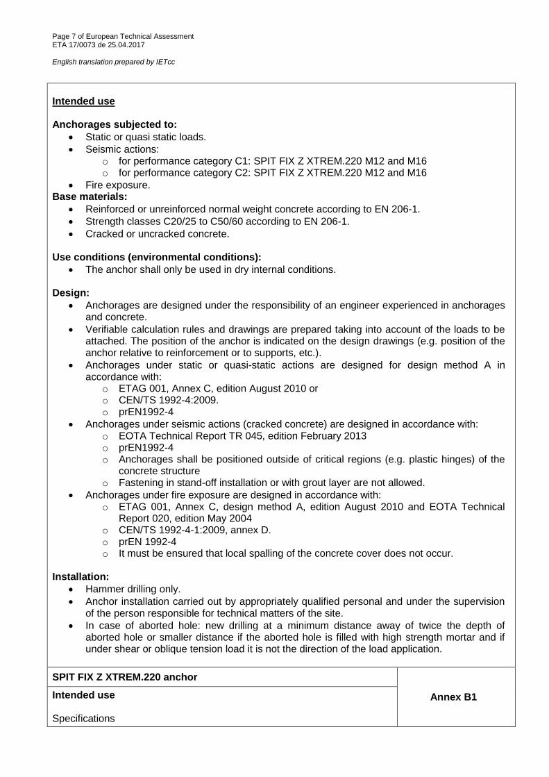
Intended use Anchorages subjected to:
Static or quasi static loads.
Seismic actions: o for performance category C1: SPIT FIX Z XTREM.220 M12 and M16 o for performance category C2: SPIT FIX Z XTREM.220 M12 and M16
Fire exposure. Base materials:
Reinforced or unreinforced normal weight concrete according to EN 206-1.
Strength classes C20/25 to C50/60 according to EN 206-1.
Cracked or uncracked concrete. Use conditions (environmental conditions):
The anchor shall only be used in dry internal conditions. Design:
Anchorages are designed under the responsibility of an engineer experienced in anchorages and concrete.
Verifiable calculation rules and drawings are prepared taking into account of the loads to be attached. The position of the anchor is indicated on the design drawings (e.g. position of the anchor relative to reinforcement or to supports, etc.).
Anchorages under static or quasi-static actions are designed for design method A in accordance with:
o ETAG 001, Annex C, edition August 2010 or o CEN/TS 1992-4:2009. o prEN1992-4
Anchorages under seismic actions (cracked concrete) are designed in accordance with: o EOTA Technical Report TR 045, edition February 2013 o prEN1992-4 o Anchorages shall be positioned outside of critical regions (e.g. plastic hinges) of the
concrete structure o Fastening in stand-off installation or with grout layer are not allowed.
Anchorages under fire exposure are designed in accordance with: o ETAG 001, Annex C, design method A, edition August 2010 and EOTA Technical
Report 020, edition May 2004 o CEN/TS 1992-4-1:2009, annex D. o prEN 1992-4 o It must be ensured that local spalling of the concrete cover does not occur.
Installation:
Hammer drilling only.
Anchor installation carried out by appropriately qualified personal and under the supervision of the person responsible for technical matters of the site.
In case of aborted hole: new drilling at a minimum distance away of twice the depth of aborted hole or smaller distance if the aborted hole is filled with high strength mortar and if under shear or oblique tension load it is not the direction of the load application.
SPIT FIX Z XTREM.220 anchor
Annex B1 Intended use Specifications

Page 8 of European Technical Assessment ETA 17/0073 de 25.04.2017 English translation prepared by IETcc
Table C1: Installation parameters for SPIT FIX Z XTREM.220 anchor
Installation parameters Performances
M12 x 220 M16 x 220
do Nominal diameter of drill bit: [mm] 12 16
df Fixture clearance hole diameter:
[mm] 14 18
Tinst Nominal installation torque: [Nm] 60 100
L Total length of the bolt: [mm] 220 220
hmin Minimum thickness of concrete member:
[mm] 140 170
h1 Depth of drilled hole: [mm] 85 105
hnom Overall anchor embedment depth in the concrete:
[mm] 80 97
hef Effective anchorage depth: [mm] 70 85
tfix Thickness of fixture: [mm] 124 103
smin Minimum allowable spacing: [mm] 70 85
cmin Minimum allowable distance: [mm] 70 85
Installation process
SPIT FIX Z XTREM.220 anchor
Annex C1 Performances Installation parameters and installation procedure

Page 9 of European Technical Assessment ETA 17/0073 de 25.04.2017 English translation prepared by IETcc
Table C2: Characteristic values to tension loads of design method A according to ETAG 001, Annex C or CEN/TS 1992-4 for SPIT FIX Z XTREM.220 anchor
Characteristic values of resistance to tension loads of design according to design method A
Performance
M12 x 220 M16 x 220
Tension loads: steel failure
NRk,s Characteristic resistance: [kN] 40.4 72.7
γMs Partial safety factor: [-] 1.5 1.5
Tension loads: pull-out failure in concrete
NRk,p,ucr Characteristic resistance in C20/25 uncracked concrete:
[kN] 20 35
NRk,p,cr Characteristic resistance in C20/25 cracked concrete:
[kN] 12 25
22)
ins1)
Installation safety factor: [-] 1.0 1.0
ψc Increasing factor for
N0Rk,p
C30/37 [-] 1.22 1.22
C40/50 [-] 1.41 1.41
C50/60 [-] 1.55 1.55
Tension loads: concrete cone and splitting failure
hef Effective embedment depth: [mm] 70 85
kucr,N Factor for uncracked concrete: [-] 10.1
kcr.N Factor for cracked concrete: [-] 7,2
22)
ins1)
Installation safety factor: [-] 1.0 1.0
scr,N Concrete cone failure:
[mm] 3 x hef
ccr,N [mm] 1.5 x hef
scr,sp Splitting failure: [mm] 350 425
ccr,sp [mm] 175 213 1)
Parameter relevant only for design according to CEN/TS 1992-4:2009 2)
Parameter relevant only for design according to ETAG 001, Annex C
SPIT FIX Z XTREM.220 anchor
Annex C2 Performances Characteristic values for tension loads

Page 10 of European Technical Assessment ETA 17/0073 de 25.04.2017 English translation prepared by IETcc
Table C3: Characteristic values to shear loads of design method A according to ETAG 001, Annex C or CEN/TS 1992- for SPIT FIX Z XTREM.220 anchor Table C4: Displacements under tension load for SPIT FIX Z XTREM.220 anchor
Displacements under tension loads Performance
M12 M16 SPIT FIX Z XTREM.220
N Service tension load: [kN] 6.3 10.4
δN0 Short term displacement: [mm] 1.0 0.4
δN∞ Long term displacement: [mm] 1.9 1.9
Table C5: Displacements under shear load for SPIT FIX Z XTREM.220 anchor
Displacements under shear loads Performance
M12 M16 SPIT FIX Z XTREM.220
V Service shear load: [kN] 8.5 15.1
δV0 Short term displacement: [mm] 1.8 1.9
δV∞ Long term displacement: [mm] 2.7 2.9
Characteristic values of resistance to shear loads of design according to design method A
Performance
M12 x 220 M16 x 220
Shear loads: steel failure without lever arm
VRk,s Characteristic resistance: [kN] 25.3 47.1
k21)
k2 factor: [-] 1.0
γMs Partial safety factor: [-] 1.25 1.25
Shear loads: steel failure with lever arm
M0
Rk,s Characteristic bending moment:
[Nm] 78.6 199.8
γMs Partial safety factor: [-] 1.25 1.25
Shear loads: concrete pryout failure
k2)
k3
1) k factor: [-] 2 2
22)
ins1)
Installation safety factor: [-] 1.0
Shear loads: concrete edge failure
lf Effective length of anchor under shear loads:
[mm] 70 85
dnom Outside anchor diameter: [mm] 12 16
22)
ins1)
Installation safety factor: [-] 1.0
1) Parameter relevant only for design according to CEN/TS 1992-4:2009
2) Parameter relevant only for design according to ETAG 001, Annex C
SPIT FIX Z XTREM.220 anchor
Annex C3 Performances Displacements under tension and shear loads

Page 11 of European Technical Assessment ETA 17/0073 de 25.04.2017 English translation prepared by IETcc
Table C6: Design information for seismic performance C1 SPIT FIX Z XTREM.220 anchor
Design information for seismic performance C1 Performance
M12 x 220 M16 x 220
Steel failure for tension and shear failure
NRk,s,seis Characteristic tension steel failure:
[kN] 40.4 72.7
γMs,N Partial safety factor: [-] 1.5 1.5
VRk,p,seis Characteristic shear steel failure:
[kN] 17.8 33.0
γMs,V Partial safety factor: [-] 1.25 1.25
Pull out failure
NRk,p,seis Characteristic pull out failure: [kN] 8.4 17.5
22)
ins1)
Installation safety factor: [-] 1.0 1.0
Concrete cone failure
hef Effective embedment depth: [mm] 70 85
scr,N Spacing: [mm] 3 x hef
ccr,N Edge distance: [mm] 1.5 x hef
22)
ins1)
Installation safety factor: [-] 1.0 1.0
Concrete pryout failure
k2)
k31)
k factor: [-] 2 2
Concrete edge failure
lf Effective length of anchor: [kN] 70 85
dnom Outside anchor diameter: [-] 12 16 1) Parameter relevant only for design according to CEN/TS 1992-4:2009
2) Parameter relevant only for design according to ETAG 001, Annex C
SPIT FIX Z XTREM.220 anchor
Annex C4 Performances Design information for seismic performance C1

Page 12 of European Technical Assessment ETA 17/0073 de 25.04.2017 English translation prepared by IETcc
Table C7: Design information for seismic performance C2 SPIT FIX Z XTREM.220 anchor
Design information for seismic performance C2 Performance
M12 x 220 M16 x 220
Steel failure for tension and shear failure
NRk,s,seis Characteristic tension steel failure:
[kN] 40.4 72.7
γMs,N Partial safety factor: [-] 1.5 1.5
VRk,p,seis Characteristic shear steel failure:
[kN] 17.8 33.0
γMs,V Partial safety factor: [-] 1.25 1.25
Pull out failure
NRk,p,seis Characteristic pull out failure: [kN] 5.2 8.9
22)
ins1)
Installation safety factor: [-] 1.0 1.0
Concrete cone failure
hef Effective embedment depth: [mm] 70 85
scr,N Spacing: [mm] 3 x hef
ccr,N Edge distance: [mm] 1.5 x hef
22)
ins1)
Installation safety factor: [-] 1.0 1.0
Concrete pryout failure
k2)
k31)
k factor: [-] 2 2
Concrete edge failure
lf Effective length of anchor: [kN] 70 85
dnom Outside anchor diameter: [-] 12 16
Displacements
δN,seis (DSL) Displacement Damage Limitation State:
3) 4)
[mm] 2.34 3.99
δV seis (DSL) [mm] 5.53 5.96
δN,seis (USL) Displacement Ultimate Limit State:
3)
[mm] 9.54 10.17
δV,seis (USL [mm] 9.08 10.66 1) Parameter relevant only for design according to CEN/TS 1992-4:2009
2) Parameter relevant only for design according to ETAG 001, Annex C
3) The listed displacements represent mean values
4) A small displacement may be required in the design in the case of displacements sensitive fastening
of “rigid” supports. The characteristics resistance associated with such small displacements may be determined by linear interpolation or proportional reduction.
SPIT FIX Z XTREM.220 anchor
Annex C5 Performances Design information for seismic performance C2

Page 13 of European Technical Assessment ETA 17/0073 de 25.04.2017 English translation prepared by IETcc
Table C8: Characteristic values for resistance to fire SPIT FIX Z XTREM.220 anchor
Anchor SPIT FIX Z XTREM.220 M12 x 220 M16 x 220
Steel failure
NRk,s,fi Characteristic tension resistance
R30 [kN] 1,7 3,1
R60 [kN] 1,3 2,4
R90 [kN] 1,1 2,0
R120 [kN] 0,8 1,6
VRk,s,fi Characteristic shear resistance
R30 [kN] 1,7 3,1
R60 [kN] 1,3 2,4
R90 [kN] 1,1 2,0
R120 [kN] 0,8 1,6
M0Rk,s,fi Characteristic bending resistance
R30 [kN] 2,6 6,7
R60 [kN] 2,0 5,0
R90 [kN] 1,7 4,3
R120 [kN] 1,3 3,3
Pull out failure
NRk,p,fi Characteristic resistance
R30
R60
R90
[kN] 3,0 6,3
R120 [kN] 2,4 5,0
Concrete cone failure4)
NRk,p,fi Characteristic resistance
R30
R60
R90
[kN] 7,4 12,0
R120 [kN] 5,9 9,6
scr.N,fi R30 to R120 [mm] 4 x hef
ccr.N,fi R30 to R120 [mm] 2 x hef
In case of fire attack from more than one side the minimum edge distance shall be ≥ 300 mm
and 2 x hef
Concrete pry out failure
k2)
k3
1)
R30 to R120 [-] 2 2
1) Parameter relevant only for design according to CEN/TS 1992-4:2009
2) Parameter relevant only for design according to ETAG 001, Annex C
4) As a rule, splitting failure can be neglected since cracked concrete and reinforcement is
assumed.
SPIT FIX Z XTREM.220 anchor
Annex C6 Performances Characteristic values for resistance to fire