Embed Size (px)
Citation preview
Z6716.14 8.06.04-824/13
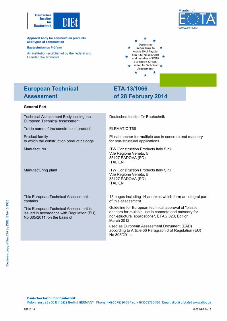
European Technical Assessment
ETA-13/1066 of 28 February 2014
General Part
Technical Assessment Body issuing the European Technical Assessment:
Deutsches Institut für Bautechnik
Trade name of the construction product ELEMATIC T66
Product family to which the construction product belongs
Plastic anchor for multiple use in concrete and masonry for non-structural applications
Manufacturer ITW Construction Products Italy S.r.l. V.le Regione Veneto, 5 35127 PADOVA (PD) ITALIEN
Manufacturing plant ITW Construction Products Italy S.r.l. V.le Regione Veneto, 5 35127 PADOVA (PD) ITALIEN
This European Technical Assessment contains
18 pages including 14 annexes which form an integral part of this assessment
This European Technical Assessment is issued in accordance with Regulation (EU) No 305/2011, on the basis of
Guideline for European technical approval of "plastic anchors for multiple use in concrete and masonry for non-structural applications", ETAG 020, Edition March 2012,
used as European Assessment Document (EAD) according to Article 66 Paragraph 3 of Regulation (EU) No 305/2011.
Ele
ctro
nic
copy
of t
he E
TA b
y D
IBt:
ETA
-13/
1066
European Technical Assessment ETA-13/1066
Page 2 of 18 | 28 February 2014
Z6716.14 8.06.04-824/13
The European Technical Assessment is issued by the Technical Assessment Body in its official language. Translations of this European Technical Assessment in other languages shall fully correspond to the original issued document and shall be identified as such.
Communication of this European Technical Assessment, including transmission by electronic means, shall be in full. However, partial reproduction may only be made with the written consent of the issuing Technical Assessment Body. Any partial reproduction has to be identified as such.
This European Technical Assessment may be withdrawn by the issuing Technical Assessment Body, in particular pursuant to information by the Commission according to Article 25 Paragraph 3 of Regulation (EU) No 305/2011.
Ele
ctro
nic
copy
of t
he E
TA b
y D
IBt:
ETA
-13/
1066

European Technical Assessment ETA-13/1066
Page 3 of 18 | 28 February 2014
Z6716.14 8.06.04-824/13
Specific part
1 Technical description of the product
The frame anchor Elematic T66 is a plastic anchor consisting of a plastic sleeve made of polyamide and an accompanying specific screw of galvanised steel or of stainless steel.
The plastic sleeve is expanded by screwing in the specific screw which presses the sleeve against the wall of the drilled hole.
The Illustration and the description of the product are given in Annex A.
2 Specification of the intended use in accordance with the applicable European Assessment Document
The performances given in Section 3 are only valid if the anchor is used in compliance with the specifications and conditions given in Annex B.
The verifications and assessment methods on which this European Technical Assessment is based lead to the assumption of a working life of the anchor of 50 years. The indications given on the working life cannot be interpreted as a guarantee given by the producer, but are to be regarded only as a means for choosing the right products in relation to the expected economically reasonable working life of the works.
3 Performance of the product and references to the methods used for its assessment
3.1 Mechanical resistance and stability (BWR 1)
Requirements with respect to the mechanical resistance and stability of non load bearing parts of the works are not included in this Basic requirement but are under the Basic Requirement safety in use.
3.2 Safety in case of fire (BWR 2)
Essential characteristic Performance
Reaction to fire Anchorages satisfy requirements for Class A1
Resistance to fire No performance determined (NPD)
3.3 Hygiene, health and the environment (BWR 3)
Not relevant.
3.4 Safety in use (BWR 4)
Essential characteristic Performance
Characteristic resistance for tension and shear loads See Annex C 1 – C 6
Characteristic resistance for bending moments See Annex C 1
Displacements under shear and tension loads See Annex C 1, C 6
Edge distances and spacings See Annex B 3, B 4
Ele
ctro
nic
copy
of t
he E
TA b
y D
IBt:
ETA
-13/
1066
European Technical Assessment ETA-13/1066
Page 4 of 18 | 28 February 2014
Z6716.14 8.06.04-824/13
3.5 Protection against noise (BWR 5)
Not relevant.
3.6 Energy economy and heat retention (BWR 6)
Not relevant.
3.7 Sustainable use of natural resources (BWR 7)
For the sustainable use of natural resources no performance was investigated for this product.
3.8 General aspects
The verification of durability is part of testing of the essential characteristics. Durability is only ensured if the specifications of intended use according to Annex B are kept.
4 Assessment and verification of constancy of performance (AVCP) system applied, with reference to its legal base
According to Decision of the Commission of 27 June 1997 (97/463/EC) (Official Journal of the European Communities L 198 of 25.07.1997, p. 31–32) the system of assessment and verification of constancy of performance (see Annex V and Article 65 Paragraph 2 to Regulation (EU) No 305/2011) given in the following table applies.
Product Intended use(s) Level or class System
Plastic anchors for use in concrete and masonry
For use in systems, such as façade systems, for fixing or supporting elements which contribute to the
stability of the systems
― 2+
5 Technical details necessary for the implementation of the AVCP system, as provided in the applicable European Assessment Document
Technical details necessary for the implementation of the AVCP system are laid down in the control plan deposited at Deutsches Institut für Bautechnik.
Issued in Berlin on 28 February 2014 by Deutsches Institut für Bautechnik
Dr.-Ing. Karsten Kathage beglaubigt:
Vice-President E. Aksünger
Ele
ctro
nic
copy
of t
he E
TA b
y D
IBt:
ETA
-13/
1066
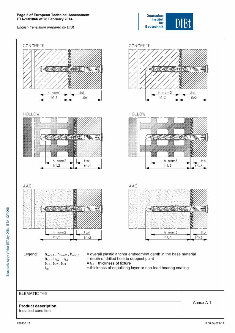
Page 5 of European Technical Assessment ETA-13/1066 of 28 February 2014 English translation prepared by DIBt
Z96133.13 8.06.04-824/13
ELEMATIC T66
Product description Installed condition
Annex A 1
Legend: hnom,1 , hnom,2 , hnom,3 = overall plastic anchor embedment depth in the base material h1,1 , h1,2 , h1,3 = depth of drilled hole to deepest point tfix1 , tfix2 , tfix3 = ttol + thickness of fixture ttol = thickness of equalizing layer or non-load bearing coating
Ele
ctro
nic
copy
of t
he E
TA b
y D
IBt:
ETA
-13/
1066

Page 6 of European Technical Assessment ETA-13/1066 of 28 February 2014 English translation prepared by DIBt
Z96133.13 8.06.04-824/13
ELEMATIC T66
Product description Anchor types and specific screw
Annex A 2
Ele
ctro
nic
copy
of t
he E
TA b
y D
IBt:
ETA
-13/
1066
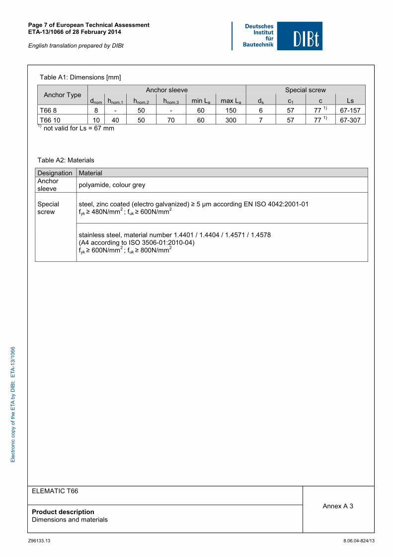
Page 7 of European Technical Assessment ETA-13/1066 of 28 February 2014 English translation prepared by DIBt
Z96133.13 8.06.04-824/13
ELEMATIC T66
Product description Dimensions and materials
Annex A 3
Table A1: Dimensions [mm]
Anchor Type Anchor sleeve Special screw
dnom hnom,1 hnom,2 hnom,3 min La max La ds c1 c Ls
T66 8 8 - 50 - 60 150 6 57 77 1) 67-157
T66 10 10 40 50 70 60 300 7 57 77 1) 67-307 1)
not valid for Ls = 67 mm Table A2: Materials
Designation Material Anchor sleeve
polyamide, colour grey
Special screw
steel, zinc coated (electro galvanized) ≥ 5 μm according EN ISO 4042:2001-01 fyk ≥ 480N/mm2 ; fuk ≥ 600N/mm2
stainless steel, material number 1.4401 / 1.4404 / 1.4571 / 1.4578 (A4 according to ISO 3506-01:2010-04) fyk ≥ 600N/mm2 ; fuk ≥ 800N/mm2
Ele
ctro
nic
copy
of t
he E
TA b
y D
IBt:
ETA
-13/
1066
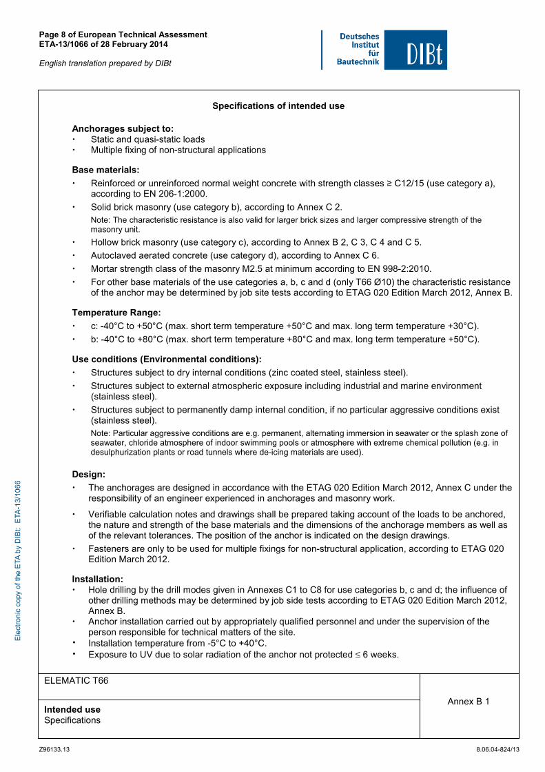
Page 8 of European Technical Assessment ETA-13/1066 of 28 February 2014 English translation prepared by DIBt
Z96133.13 8.06.04-824/13
ELEMATIC T66
Intended use Specifications
Annex B 1
Specifications of intended use
Anchorages subject to: Static and quasi-static loads Multiple fixing of non-structural applications Base materials:
Reinforced or unreinforced normal weight concrete with strength classes ≥ C12/15 (use category a), according to EN 206-1:2000.
Solid brick masonry (use category b), according to Annex C 2. Note: The characteristic resistance is also valid for larger brick sizes and larger compressive strength of the masonry unit.
Hollow brick masonry (use category c), according to Annex B 2, C 3, C 4 and C 5.
Autoclaved aerated concrete (use category d), according to Annex C 6.
Mortar strength class of the masonry M2.5 at minimum according to EN 998-2:2010.
For other base materials of the use categories a, b, c and d (only T66 Ø10) the characteristic resistance of the anchor may be determined by job site tests according to ETAG 020 Edition March 2012, Annex B.
Temperature Range:
c: -40°C to +50°C (max. short term temperature +50°C and max. long term temperature +30°C).
b: -40°C to +80°C (max. short term temperature +80°C and max. long term temperature +50°C). Use conditions (Environmental conditions):
Structures subject to dry internal conditions (zinc coated steel, stainless steel).
Structures subject to external atmospheric exposure including industrial and marine environment (stainless steel).
Structures subject to permanently damp internal condition, if no particular aggressive conditions exist (stainless steel). Note: Particular aggressive conditions are e.g. permanent, alternating immersion in seawater or the splash zone of seawater, chloride atmosphere of indoor swimming pools or atmosphere with extreme chemical pollution (e.g. in desulphurization plants or road tunnels where de-icing materials are used).
Design:
The anchorages are designed in accordance with the ETAG 020 Edition March 2012, Annex C under the responsibility of an engineer experienced in anchorages and masonry work.
Verifiable calculation notes and drawings shall be prepared taking account of the loads to be anchored, the nature and strength of the base materials and the dimensions of the anchorage members as well as of the relevant tolerances. The position of the anchor is indicated on the design drawings.
Fasteners are only to be used for multiple fixings for non-structural application, according to ETAG 020 Edition March 2012.
Installation: Hole drilling by the drill modes given in Annexes C1 to C8 for use categories b, c and d; the influence of
other drilling methods may be determined by job side tests according to ETAG 020 Edition March 2012, Annex B.
Anchor installation carried out by appropriately qualified personnel and under the supervision of the person responsible for technical matters of the site.
Installation temperature from -5°C to +40°C. Exposure to UV due to solar radiation of the anchor not protected ≤ 6 weeks.
Ele
ctro
nic
copy
of t
he E
TA b
y D
IBt:
ETA
-13/
1066

Page 9 of European Technical Assessment ETA-13/1066 of 28 February 2014 English translation prepared by DIBt
Z96133.13 8.06.04-824/13
ELEMATIC T66
Intended use Geometry and dimensions of hollow or perforated brick
Annex B 2
Table B1: Geometry and dimensions of hollow or perforated brick
Ele
ctro
nic
copy
of t
he E
TA b
y D
IBt:
ETA
-13/
1066
Page 10 of European Technical Assessment ETA-13/1066 of 28 February 2014 English translation prepared by DIBt
Z96133.13 8.06.04-824/13
ELEMATIC T66
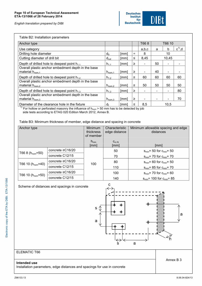
Intended use Installation parameters, edge distances and spacings for use in concrete
Annex B 3
Table B2: Installation parameters Anchor type T66 8 T66 10
Use category a,b,c a b c1),d Drilling hole diameter d0 [mm] = 8 10 Cutting diameter of drill bit dcut [mm] ≤ 8,45 10,45
Depth of drilled hole to deepest point h1,1 h1,1 [mm] ≥ - 50 - - Overall plastic anchor embedment depth in the base material hnom,1 hnom,1 [mm] ≥ - 40 - -
Depth of drilled hole to deepest point h1,2 h1,2 [mm] ≥ 60 60 60 60 Overall plastic anchor embedment depth in the base material hnom,2 hnom,2 [mm] ≥ 50 50 50 50
Depth of drilled hole to deepest point h1,3 h1,3 [mm] ≥ - - - 80 Overall plastic anchor embedment depth in the base material hnom,3 hnom,3 [mm] ≥ - - - 70
Diameter of the clearance hole in the fixture df [mm] ≤ 8,5 10,5 1) For hollow or perforated masonry the influence of hnom > 50 mm has to be detected by job side tests according to ETAG 020 Edition March 2012, Annex B.
Table B3: Minimum thickness of member, edge distance and spacing in concrete
Anchor type Minimum thickness
of member
Characteristic edge distance
Minimum allowable spacing and edge distances
hmin ccr,N [mm] [mm] [mm]
T66 8 (hnom=50) concrete ≥C16/20
100
50 smin= 50 for cmin= 50
concrete C12/15 70 smin= 70 for cmin= 70
T66 10 (hnom=40) concrete ≥C16/20 80 smin= 60 for cmin= 50
concrete C12/15 110 smin= 85 for cmin= 70
T66 10 (hnom=50) concrete ≥C16/20 100 smin= 70 for cmin= 60
concrete C12/15 140 smin= 100 for cmin= 85 Scheme of distances and spacings in concrete E
lect
roni
c co
py o
f the
ETA
by
DIB
t: E
TA-1
3/10
66

Page 11 of European Technical Assessment ETA-13/1066 of 28 February 2014 English translation prepared by DIBt
Z96133.13 8.06.04-824/13
ELEMATIC T66
Intended use Edge distances and spacings for use in masonry and AAC
Annex B 4
Table B4: Minimum distances and dimensions in masonry
Anchor type T66 8 T66 10
Minimum thickness of member hmin [mm] 110 110
Single anchor
Minimum allowable spacing amin [mm] 250 250
Minimum allowable edge distance cmin [mm] 100 100
Anchor group
Minimum allowable spacing perpendicular to free edge s1,min [mm] 200 200
Minimum allowable spacing parallel to free edge s2,min [mm] 400 400
Minimum allowable edge distance cmin [mm] 100 100
Table B5: Minimum distances and dimensions in AAC
Anchor type T66 10
Minimum thickness of member hmin [mm] 100
Single anchor
Minimum allowable spacing amin [mm] 250
Minimum allowable edge distance cmin [mm] 100
Anchor group
Minimum allowable spacing perpendicular to free edge s1,min [mm] 200
Minimum allowable spacing parallel to free edge s2,min [mm] 400
Minimum allowable edge distance cmin [mm] 100
Scheme of distances and spacings in masonry and AAC
c
s2
a
s1 a h
a
Ele
ctro
nic
copy
of t
he E
TA b
y D
IBt:
ETA
-13/
1066
Page 12 of European Technical Assessment ETA-13/1066 of 28 February 2014 English translation prepared by DIBt
Z96133.13 8.06.04-824/13
ELEMATIC T66
Intended use Installation instructions
Annex B 5
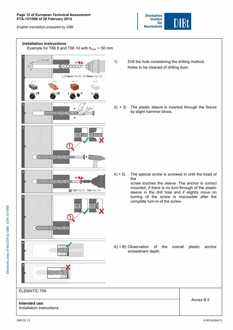
Installation instructions Example for T66 8 and T66 10 with hnom = 50 mm
1) Drill the hole considering the drilling method.
Holes to be cleaned of drilling dust.
2) + 3) The plastic sleeve is inserted through the fixture by slight hammer blows.
4) + 5) The special screw is screwed in until the head of the
screw touches the sleeve. The anchor is correct mounted, if there is no turn-through of the plastic sleeve in the drill hole and if slightly move on turning of the screw is impossible after the complete turn-in of the screw.
A) + B) Observation of the overall plastic anchor embedment depth.
Ele
ctro
nic
copy
of t
he E
TA b
y D
IBt:
ETA
-13/
1066
Page 13 of European Technical Assessment ETA-13/1066 of 28 February 2014 English translation prepared by DIBt
Z96133.13 8.06.04-824/13
ELEMATIC T66
Performances Characteristic resistance of the screw, characteristic resistance for use in concrete
Annex C 1
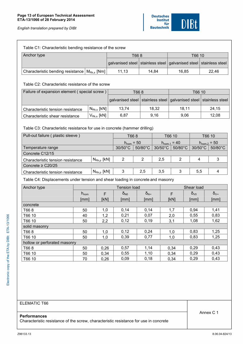
Table C1: Characteristic bending resistance of the screw
Anchor type
T66 8 T66 10
galvanised steel stainless steel galvanised steel stainless steel
Characteristic bending resistance MRk,s [Nm] 11,13 14,84 16,85 22,46
Table C2: Characteristic resistance of the screw
Failure of expansion element ( special screw ) T66 8 T66 10
galvanised steel stainless steel galvanised steel stainless steel
Characteristic tension resistance NRk,s [kN] 13,74 18,32 18,11 24,15
Characteristic shear resistance VRk,s [kN] 6,87 9,16 9,06 12,08
Table C3: Characteristic resistance for use in concrete (hammer drilling)
Pull-out failure ( plastic sleeve ) T66 8 T66 10 T66 10
hnom = 50 hnom,1 = 40 hnom,2 = 50 Temperature range 30/50°C 50/80°C 30/50°C 50/80°C 30/50°C 50/80°C
Concrete C12/15
Characteristic tension resistance NRk,p [kN] 2 2 2,5 2 4 3
Concrete ≥ C20/25
Characteristic tension resistance NRk,p [kN] 3 2,5 3,5 3 5,5 4
Table C4: Displacements under tension and shear loading in concrete and masonry
Anchor type Tension load Shear load
hnom F δN0 δN∞ F δV0 δV∞
[mm] [kN] [mm] [mm] [kN] [mm] [mm] concrete T66 8 50 1,0 0,14 0,14 1,7 0,94 1,41 T66 10 40 1,2 0,21 0,07 2,0 0,55 0,83
T66 10 50 2,2 0,12 0,19 3,1 1,08 1,62 solid masonry T66 8 50 1,0 0,12 0,24 1,0 0,83 1,25
T66 10 50 1,0 0,39 0,77 1,0 0,83 1,25 hollow or perforated masonry T66 8 50 0,26 0,57 1,14 0,34 0,29 0,43 T66 10 50 0,34 0,55 1,10 0,34 0,29 0,43
T66 10 70 0,26 0,09 0,18 0,34 0,29 0,43
Ele
ctro
nic
copy
of t
he E
TA b
y D
IBt:
ETA
-13/
1066
Page 14 of European Technical Assessment ETA-13/1066 of 28 February 2014 English translation prepared by DIBt
Z96133.13 8.06.04-824/13
ELEMATIC T66
Performances Characteristic resistance for use in solid masonry
Annex C 2
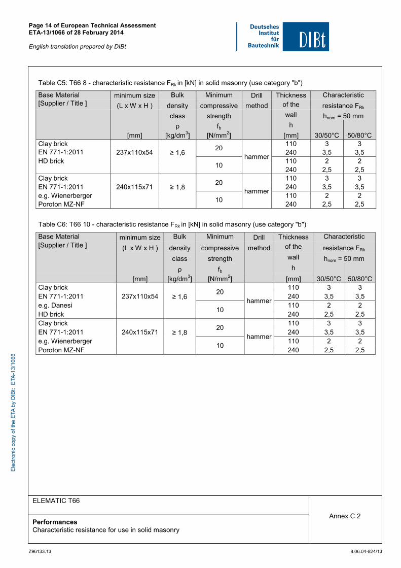
Table C5: T66 8 - characteristic resistance FRk in [kN] in solid masonry (use category "b")
Base Material minimum size Bulk Minimum Drill Thickness Characteristic [Supplier / Title ] (L x W x H ) density compressive method of the resistance FRk class strength wall hnom = 50 mm ρ fb h [mm] [kg/dm3] [N/mm2] [mm] 30/50°C 50/80°C Clay brick
20 hammer
110 3 3 EN 771-1:2011 237x110x54 ≥ 1,6 240 3,5 3,5 HD brick
10 110 2 2
240 2,5 2,5 Clay brick
20 hammer
110 3 3 EN 771-1:2011 240x115x71 ≥ 1,8 240 3,5 3,5 e.g. Wienerberger
10 110 2 2
Poroton MZ-NF 240 2,5 2,5
Table C6: T66 10 - characteristic resistance FRk in [kN] in solid masonry (use category "b")
Base Material minimum size Bulk Minimum Drill Thickness Characteristic [Supplier / Title ] (L x W x H ) density compressive method of the resistance FRk class strength wall hnom = 50 mm ρ fb h [mm] [kg/dm3] [N/mm2] [mm] 30/50°C 50/80°CClay brick
20 hammer
110 3 3 EN 771-1:2011 237x110x54 ≥ 1,6 240 3,5 3,5 e.g. Danesi
10 110 2 2
HD brick 240 2,5 2,5 Clay brick
20 hammer
110 3 3 EN 771-1:2011 240x115x71 ≥ 1,8 240 3,5 3,5 e.g. Wienerberger
10 110 2 2
Poroton MZ-NF 240 2,5 2,5
Ele
ctro
nic
copy
of t
he E
TA b
y D
IBt:
ETA
-13/
1066
Page 15 of European Technical Assessment ETA-13/1066 of 28 February 2014 English translation prepared by DIBt
Z96133.13 8.06.04-824/13
ELEMATIC T66
Performances Characteristic resistance for use in hollow or perforated masonry
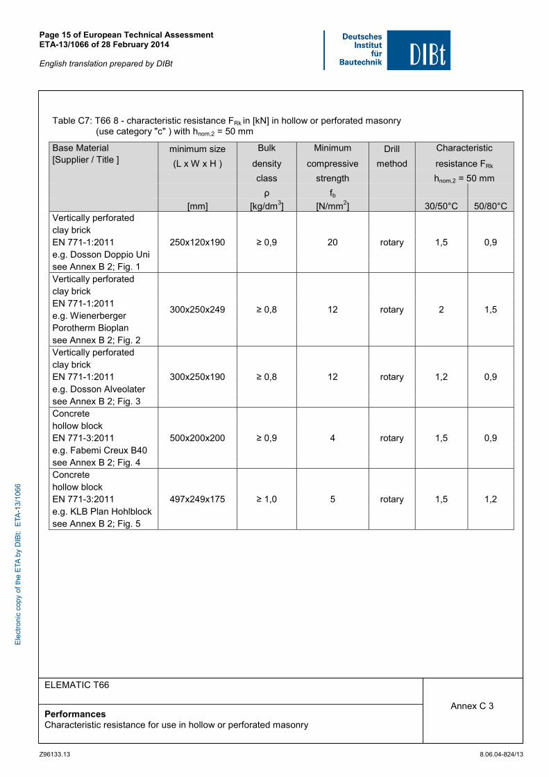
Annex C 3
Table C7: T66 8 - characteristic resistance FRk in [kN] in hollow or perforated masonry (use category "c" ) with hnom,2 = 50 mm
Base Material minimum size Bulk Minimum Drill Characteristic [Supplier / Title ] (L x W x H ) density compressive method resistance FRk class strength hnom,2 = 50 mm ρ fb [mm] [kg/dm3] [N/mm2] 30/50°C 50/80°C Vertically perforated
250x120x190 ≥ 0,9 20 rotary 1,5 0,9 clay brick EN 771-1:2011 e.g. Dosson Doppio Uni see Annex B 2; Fig. 1 Vertically perforated
300x250x249 ≥ 0,8 12 rotary 2 1,5
clay brick EN 771-1:2011 e.g. Wienerberger Porotherm Bioplan see Annex B 2; Fig. 2 Vertically perforated
300x250x190 ≥ 0,8 12 rotary 1,2 0,9 clay brick EN 771-1:2011 e.g. Dosson Alveolater see Annex B 2; Fig. 3 Concrete
500x200x200 ≥ 0,9 4 rotary 1,5 0,9 hollow block EN 771-3:2011 e.g. Fabemi Creux B40 see Annex B 2; Fig. 4 Concrete
497x249x175 ≥ 1,0 5 rotary 1,5 1,2 hollow block EN 771-3:2011 e.g. KLB Plan Hohlblock see Annex B 2; Fig. 5
Ele
ctro
nic
copy
of t
he E
TA b
y D
IBt:
ETA
-13/
1066
Page 16 of European Technical Assessment ETA-13/1066 of 28 February 2014 English translation prepared by DIBt
Z96133.13 8.06.04-824/13
ELEMATIC T66
Performances Characteristic resistance for use in hollow or perforated masonry
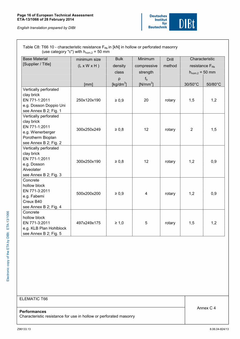
Annex C 4
Table C8: T66 10 - characteristic resistance FRk in [kN] in hollow or perforated masonry (use category "c") with hnom,2 = 50 mm
Base Material minimum size Bulk Minimum Drill Characteristic [Supplier / Title] (L x W x H ) density compressive method resistance FRk class strength hnom,2 = 50 mm ρ fb [mm] [kg/dm3] [N/mm2] 30/50°C 50/80°C Vertically perforated
20 rotary
clay brick EN 771-1:2011 250x120x190 ≥ 0,9 1,5 1,2 e.g. Dosson Doppio Uni see Annex B 2; Fig. 1 Vertically perforated
300x250x249 ≥ 0,8 12 rotary 2 1,5
clay brick EN 771-1:2011 e.g. Wienerberger Porotherm Bioplan see Annex B 2; Fig. 2 Vertically perforated
300x250x190 ≥ 0,8 12 rotary 1,2 0,9
clay brick EN 771-1:2011 e.g. Dosson Alveolater see Annex B 2; Fig. 3 Concrete
500x200x200 ≥ 0,9 4 rotary 1,2 0,9
hollow block EN 771-3:2011 e.g. Fabemi Creux B40 see Annex B 2; Fig. 4 Concrete
497x249x175 ≥ 1,0 5 rotary 1,5 1,2 hollow block EN 771-3:2011 e.g. KLB Plan Hohlblock see Annex B 2; Fig. 5
Ele
ctro
nic
copy
of t
he E
TA b
y D
IBt:
ETA
-13/
1066
Page 17 of European Technical Assessment ETA-13/1066 of 28 February 2014 English translation prepared by DIBt
Z96133.13 8.06.04-824/13
ELEMATIC T66
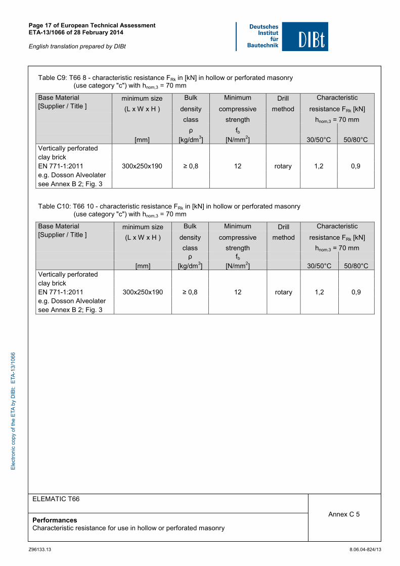
Performances Characteristic resistance for use in hollow or perforated masonry
Annex C 5
Table C9: T66 8 - characteristic resistance FRk in [kN] in hollow or perforated masonry (use category "c") with hnom,3 = 70 mm
Base Material minimum size Bulk Minimum Drill Characteristic [Supplier / Title ] (L x W x H ) density compressive method resistance FRk [kN] class strength hnom,3 = 70 mm ρ fb [mm] [kg/dm3] [N/mm2] 30/50°C 50/80°C Vertically perforated
300x250x190 ≥ 0,8 12 rotary 1,2 0,9 clay brick EN 771-1:2011 e.g. Dosson Alveolater see Annex B 2; Fig. 3
Table C10: T66 10 - characteristic resistance FRk in [kN] in hollow or perforated masonry (use category "c") with hnom,3 = 70 mm
Base Material minimum size Bulk Minimum Drill Characteristic [Supplier / Title ] (L x W x H ) density compressive method resistance FRk [kN] class strength hnom,3 = 70 mm ρ fb [mm] [kg/dm3] [N/mm2] 30/50°C 50/80°C Vertically perforated
300x250x190 ≥ 0,8 12 rotary 1,2 0,9 clay brick EN 771-1:2011 e.g. Dosson Alveolater see Annex B 2; Fig. 3
Ele
ctro
nic
copy
of t
he E
TA b
y D
IBt:
ETA
-13/
1066
Page 18 of European Technical Assessment ETA-13/1066 of 28 February 2014 English translation prepared by DIBt
Z96133.13 8.06.04-824/13
ELEMATIC T66
Performances Characteristic resistance and displacements for use in autoclaved aerated concrete
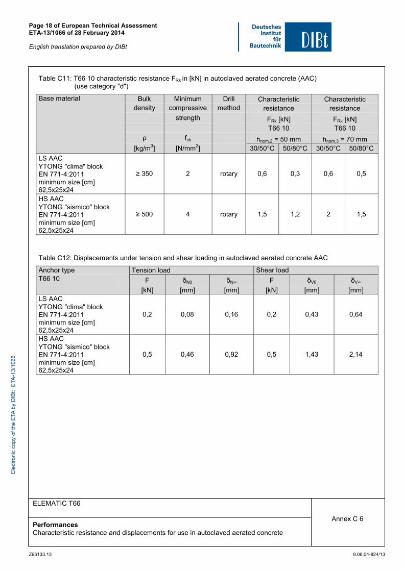
Annex C 6
Table C11: T66 10 characteristic resistance FRk in [kN] in autoclaved aerated concrete (AAC) (use category "d")
Base material Bulk Minimum Drill Characteristic Characteristic density compressive method resistance resistance
strength FRk [kN] FRk [kN] T66 10 T66 10
ρ fck hnom,2 = 50 mm hnom,3 = 70 mm [kg/m3] [N/mm2] 30/50°C 50/80°C 30/50°C 50/80°C
LS AAC
≥ 350 2 rotary 0,6 0,3 0,6 0,5 YTONG "clima" block EN 771-4:2011 minimum size [cm] 62,5x25x24 HS AAC
≥ 500 4 rotary 1,5 1,2 2 1,5 YTONG "sismico" block EN 771-4:2011 minimum size [cm] 62,5x25x24
Table C12: Displacements under tension and shear loading in autoclaved aerated concrete AAC
Anchor type Tension load Shear load T66 10 F δN0 δN∞ F δV0 δV∞
[kN] [mm] [mm] [kN] [mm] [mm] LS AAC
0,2 0,08 0,16 0,2 0,43 0,64 YTONG "clima" block EN 771-4:2011 minimum size [cm] 62,5x25x24 HS AAC
0,5 0,46 0,92 0,5 1,43 2,14 YTONG "sismico" block EN 771-4:2011 minimum size [cm] 62,5x25x24
Ele
ctro
nic
copy
of t
he E
TA b
y D
IBt:
ETA
-13/
1066