Embed Size (px)
Citation preview

ETA-Danmark A/S Göteborg Plads 1 DK-2150 Nordhavn Tel. +45 72 24 59 00 Fax +45 72 24 59 04 Internet www.etadanmark.dk
MEMBER OF EOTA
Authorised and notified according to Article 29 of the Regulation (EU) No 305/2011 of the European Parliament and of the Council of 9 March 2011
European Technical Assessment ETA-14/0274 of 20/12/2017
I General Part
Technical Assessment Body issuing the ETA and designated according to Article 29 of the Regulation (EU) No 305/2011: ETA-Danmark A/S
Trade name of the construction product:
Würth hold downs type V Plus Lx90x65x3,0, V Plus Lx90x65x4,0, type HTA Lx60x60x3,0 and HTA Lx80x80x3,0 and Angle Bracket Type V, Type V-MH and Concrete Flat Steel Anchor
Product family to which the above construction product belongs:
EC PAC 13: Three-dimensional nailing plate (Angle brackets and hold-downs for timber-to-timber or timber-to-concrete or steel connections)
Manufacturer: Adolf Würth GmbH & Co. KG Reinhold Würth Strasse 12 – 17 D-74650 Künzelsau Tel. +49 7940 15 0 Fax +49 7940 15 1000 Internet www.wuerth.com
Manufacturing plant: Adolf Würth GmbH & Co. KG
Manufacturing plant II
This European Technical Assessment contains:
46 pages including 2 annexes which form an integral part of the document
This European Technical Assessment is issued in accordance with Regulation (EU) No 305/2011, on the basis of:
Guideline for European Technical Approval (ETAG) No. 015 Three Dimensional Nailing Plates, April 2013, used as European Assessment Document (EAD).
This version replaces:
The ETA with the same number issued on 2014-08-18

Page 2 of 46 of European Technical Assessment no. ETA-14/0274, issued on 2017-12-21
Translations of this European Technical Assessment in
other languages shall fully correspond to the original
issued document and should be identified as such.
Communication of this European Technical
Assessment, including transmission by electronic
means, shall be in full (excepted the confidential
Annex(es) referred to above). However, partial
reproduction may be made, with the written consent of
the issuing Technical Assessment Body. Any partial
reproduction has to be identified as such.

Page 3 of 46 of European Technical Assessment no. ETA-14/0274, issued on 2017-12-21
II SPECIFIC PART OF THE
EUROPEAN TECHNICAL
ASSESSMENT
1 Technical description of product and
intended use
Technical description of the product
Würth angle brackets and hold-downs are one-piece
welded or similarly joined face-fixed nailing plates to be
used in timber to concrete or to steel or in timber to
timber connections. They are connected to construction
members made of timber or wood-based products with
profiled (ringed shank) nails or screws according to EN
14592 or ETA and to concrete or steel members with
bolts or metal anchors.
The hold downs with a steel plate thickness of 3 mm to
4 mm are made from zinc-coated or zinc-magnesium-
coated steel grade S235 and S355 according to EN
10346, or steel grade DX 51D according to EN 10111
with Re ≥ 200 N/mm², Rm ≥ 270 N/mm² and A80 ≥ 22%
or steel grade DX51/DD11 according to EN 10111 with
Re ≥ 200 N/mm², Rm ≤ 440 N/mm² and A80 ≥ 23% with
tolerances according to EN 10143 and are available in
various sizes.
The angle brackets are made from pre-galvanized steel
S 250 GD + Z 275 according to EN 10346 or from steel
DX51/DD 11 according to EN 10111 with a minimum
yield strength of Rel ≥ 251 N/mm² with toleracnes
according to EN 10143
Dimensions, hole positions and typical installations are
shown in Annex A and B.
2 Specification of the intended use in
accordance with the applicable EAD
The angle brackets and hold-downs are intended for use
in making connections in load bearing timber structures,
as a connection between a column and a concrete, steel
or timber member, where requirements for mechanical
resistance and stability and safety in use in the sense of
the Basic Works Requirements 1 and 4 of Regulation
(EU) 305/2011 shall be fulfilled.
The connection may be with a single angle bracket or
with an angle bracket on each side of the fastened timber
member (see Annex B).
The static and kinematical behaviour of the timber
members or the supports shall be as described in Annex
B.
The wood members may be of solid timber, glued
laminated timber and similar glued members, or wood-
based structural members. These requirements to the
material of the wood members can be fulfilled by using
timber or wood based material with a characteristic
density from 290 kg/m³ to 420 kg/m³. This is fulfilled
for the following materials:
• Solid timber according to EN 14081,
• Glued solid timber according to EN 14080,
• Glulam according to EN 14080,
• LVL according to EN 14374,
• Parallam PSL,
• Intrallam LSL,
• Cross laminated timber according to EN 16351,
• Plywood according to EN 636
Annex B states the load-carrying capacities of the hold
down connections for a characteristic density of 350
kg/m3. For timber or wood based material with a lower
characteristic density than 350 kg/m3 the load-carrying
capacities shall be reduced by the kdens factor:
For hold downs: 0,5
kdens
k350
For angle brackets: 2
k
densk
350
Where ρk is he characteristic density of the timber in
kg/m3.
The design of the connections shall be in accordance
with Eurocode 5 or a similar national Timber Code. The
wood members shall have a thickness which is larger
than the penetration depth of the fasteners into the
members.
The angle brackets and hold-downs are primarily for use
in timber structures subject to the dry, internal
conditions defined by service classes 1 and 2 of
Eurocode 5 and for connections subject to static or
quasi-static loading.
The angle brackets and hold downs may also be used in
outdoor timber structures, service class 3, when a
corrosion protection in accordance with Eurocode 5 is
applied, or when stainless steel with similar or better
characteristic yield and ultimate strength is employed. If
a stainless steel with a lower characteristic yield or
ultimate strength is employed, the load-carrying

Page 4 of 46 of European Technical Assessment no. ETA-14/0274, issued on 2017-12-21
capacities Ft,Rk in Table 1 (see annex B) are to be
reduced proportionally.
The scope of the brackets regarding resistance to
corrosion shall be defined according to national
provisions that apply at the installation site considering
environmental conditions.
The hold downs and angle brackets may also be used for
connections between a timber member and a member of
concrete or steel.
The provisions made in this European Technical
Assessment are based on an assumed intended working
life of the hold downs of 50 years.
The indications given on the working life cannot be
interpreted as a guarantee given by the producer or
Assessment Body, but are to be regarded only as a
means for choosing the right products in relation to the
expected economically reasonable working life of the
works.

Page 5 of 46 of European Technical Assessment no. ETA-14/0274, issued on 2017-12-21
3 Performance of the product and references to the methods used for its assessment
Characteristic
Assessment of characteristic
3.1 Mechanical resistance and stability*) (BWR1)
Characteristic load-carrying capacity
See Annex B
Stiffness
No performance Assessed
Ductility in cyclic testing
No performance Assessed
3.2 Safety in case of fire (BWR2)
Reaction to fire
The angle brackets and hold downs are made from
steel classified as Euroclass A1 in accordance
with EN 1350-1 and EC decision 96/603/EC,
amended by EC Decision 2000/605/EC
3.3 Hygiene, health and the environment (BWR3)
Influence on air quality
No dangerous materials
3.7 Sustainable use of natural resources (BWR7)
No Performance Assessed
3.8 General aspects related to the performance of
the product
The angle brackets hold downs have been assessed
as having satisfactory durability and serviceability
when used in timber structures using the timber
species described in Eurocode 5 and subject to the
conditions defined by service class 1 and 2
Identification
See Annex A
*) See additional information in section 3.9 – 3.12.
In addition to the specific clauses relating to dangerous substances contained in this European technical Assessment,
there may be other requirements applicable to the products falling within its scope (e.g. transposed European legislation
and national laws, regulations and administrative provisions). In order to meet the provisions of the Construction
Products Regulation, these requirements need also to be complied with, when and where they apply.

Page 6 of 46 of European Technical Assessment no. ETA-14/0274, issued on 2017-12-21
3.9 Methods of verification
Safety principles and partial factors
The characteristic load-carrying capacities are based on
the characteristic values of the nail or screw connections
and the steel plates. To obtain design values the
capacities have to be divided by different partial factors
for the material properties, the nail connection in
addition multiplied with the coefficient kmod.
According to EN 1990 (Eurocode – Basis of design)
paragraph 6.3.5 the design value of load-carrying
capacity may be determined by reducing the
characteristic values of the load-carrying capacity with
different partial factors.
Thus, the characteristic values of the load–carrying
capacity are determined also for timber failure FRk,H
(obtaining the embedment strength of nails or screws
subjected to shear or the withdrawal capacity of the most
loaded nail or screw, respectively) as well as for steel
plate failure FRk,S. The design value of the load–carrying
capacity is the smaller value of both load–carrying
capacities.
mod Rk,H Rk,SRd
M,H M,S
k F FF min ;
Therefore, for timber failure the load duration class and
the service class are included. The different partial
factors M for steel or timber, respectively, are also
correctly taken into account.
3.10 Mechanical resistance and stability See annex B for the characteristic load-carrying capacity
in the direction F1 for the hold downs and F1 to F7 for
the angle brackets.
The characteristic capacities of the hold-downs are
determined by calculation assisted by testing as
described in the EOTA Guideline 015 clause 5.1.2. They
should be used for designs in accordance with Eurocode
5 or a similar national Timber Code.
No performance has been determined in relation to
ductility of a joint under cyclic testing. The contribution
to the performance of structures in seismic zones,
therefore, has not been assessed.
No performance has been determined in relation to the
joint’s stiffness properties to be used for the analysis of
the serviceability limit state.
3.11 Aspects related to the performance of the
product
3.11.1 Corrosion protection in service class 1 and 2.
The hold downs with a steel plate thickness of 3 mm to 4
mm are made from zinc-coated or zinc-magnesium-
coated steel grade S350 and S355 according to EN
10025-2:2004, or steel grade DX 51D according to EN
10327:2004 with Re ≥ 200 N/mm², Rm ≥ 270 N/mm² and
A80 ≥ 22% or steel grade DX51/DD11 according to EN
10111:2008 with Re ≥ 200 N/mm², Rm ≤ 440 N/mm² and
A80 ≥ 23% with tolerances according to EN 10143:1993.
The angle brackets Type V 95, 135, 285 and V-MH 137
are made from steel DX51/DD 11 according to EN
10111 with a minimum yield strength of Rel ≥ 251
N/mm².
3.11.2 Corrosion protection in service class 3.
The brackets are for use in timber structures subject to the
service classes 1, 2 and 3 of Eurocode 5 and for
connections subject to static or quasi-static loading. In
service class 1 and 2 the corrosion protection is given by
hot-dip zinc coating Z275 according to EN 10147 or zinc
coating according to EN1461 with a minimum thickness
of 8 μm. In service class 3 the corrosion protection is
given by hot-dip zinc coating Z350 according to EN
10147 or zinc coating according to EN1461 with a
minimum thickness of 55 μm
3.12 General aspects related to the fitness for use of
the product
The angle brackets and hold downs are manufactured in
accordance with the provisions of this European
Technical Assessment using the manufacturing processes
as identified in the inspection of the plant by the notified
inspection body and laid down in the technical
documentation
The nailing pattern used shall be either the maximum or
the minimum pattern as defined in Annex A.
The following provisions concerning installation apply:
The structural members – the components 1 and 2 shown
in the figure on page 12 - to which the brackets are fixed
shall be:
Restrained against rotation. At a load F2/F3 and F4/F5,
the timber component is allowed to be restrained
against rotation by the angle brackets
Strength class C14 or better,
Free from wane under the bracket.
The gap between the timber members does not
exceed 3 mm.

Page 7 of 46 of European Technical Assessment no. ETA-14/0274, issued on 2017-12-21
There are no specific requirements relating to
preparation of the timber members.
The execution of the connection shall be in
accordance with the assessment holder’s technical
literature.
4 Attestation and verification of constancy
of performance (AVCP)
4.1 AVCP system According to the decision 97/638/EC of the European
Commission1, as amended, the system(s) of assessment
and verification of constancy of performance (see
Annex V to Regulation (EU) No 305/2011) is 2+.
5 Technical details necessary for the
implementation of the AVCP system, as
foreseen in the applicable EAD
Technical details necessary for the implementation of
the AVCP system are laid down in the control plan
deposited at ETA-Danmark prior to CE marking.
Issued in Copenhagen on 2017-12-21 by
Thomas Bruun
Manager, ETA-Danmark

Page 8 of 46 of European Technical Assessment no. ETA-14/0274, issued on 2017-12-21
Annex A
Product details definitions
Table A.1 Materials specification – hold downs
Hold down type Thickness (mm) Steel specification
V PLus Lx90x65x3,0 3,0 DX51D or DD11
V Plus Lx90x65x4,0 4,0 DX51D or DD11
HTA Lx60x60x3,0 3,0 S355
HTA Lx80x80x3,0 3,0 S355
Washer 30x3 3,0 S 235
Washer 37x3 3,0 S 235
Base plate HTA 58,5x50x10 10,0 S 235
Base plate HTA 79x70x20 20,0 S 235
Table A.2 Range of sizes – hold downs
Hold down type Height (mm) vertical Depth (mm) horizontal Width (mm)
V Plus Lx90x65x3,0 L - 2 L + 2 89 91 64 66
V Plus Lx90x65x4,0 L - 2 L + 2 89 91 64 66
HTA Lx60x60x3,0 L - 2 L + 2 59 61 39 41
HTA Lx80x80x3,0 L - 2 L + 2 79 81 82 84
Washer 30x3 - - 29 31 62 64
Washer 37x3 - - 36 38 36 38
Base plate HTA 58,5x50x10 - - 58 59 49 51
Base plate HTA 79x70x20 - - 78 80 69 71
Table A.3 Materials specification – angle brackets
Bracket type Thickness (mm) Steel specification
V 95 4,0 DX51D or DD11
V 135 4,0 DX51D or DD11
V-MH 137 4,0 DX51D or DD11
V 285 4,0 DX51D or DD11
Timber-concrete flat steel
anchor
Thickness (mm) Steel specification
40 x 200 x 2,0 2,0 S 250 GD + Z 275
40 x 300 x 2,0 2,0 S 250 GD + Z 275
40 x 400 x 2,0 2,0 S 250 GD + Z 275
40 x 200 x 4,0 4,0 S 250 GD + Z 275
40 x 300 x 4,0 4,0 S 250 GD + Z 275
40 x 400 x 4,0 4,0 S 250 GD + Z 275
Table A.4 Range of sizes – angle brackets
Bracket type Height (mm) Width (mm)
Min max min max
V 95 94 96 64 66
V 135 134 136 64 66
V-MH 137 136 138 64 66
V 285 284 286 64 66
Timber-concrete flat
steel anchor
Length (mm) Width (mm)
min max min max
40 x 40 x 200 200 207 39 41
40 x 40 x 300 300 307 39 41
40 x 40 x 400 400 407 39 41
40 x 40 x 200 200 207 39 41
40 x 40 x 300 300 307 39 41
40 x 40 x 400 400 407 39 41

Page 9 of 46 of European Technical Assessment no. ETA-14/0274, issued on 2017-12-21
Table A.5 Fastener specification
Fastener Size (mm) Type Finish
Diameter Length Threaded
Length
Threaded
nail
4,0 / 4,4 40 30 Ringed shank nail according to EN
14592
Electroplated
zinc
Screw 5,0 30 25 Self-tapping ASSY screw according to
ETA 11/0190
Electroplated
zinc
Screw 10,0 60 50 Self-tapping ASSY screw according to
ETA 11/0190
Electroplated
zinc
In the load-carrying-capacities of the connection the capacities for threaded nails calculated from the formulas
of Eurocode 5 are used assuming a thick steel plate when calculating the lateral nail load-carrying-capacity.
The characteristic withdrawal capacity of the nails has to be determined by calculation in accordance with EN
1995-1-1:2004, paragraph 8.3.2 (head pull-through is not relevant):
Fax,Rk = fax,k × d × tpen
Where:
fax,k Characteristic value of the withdrawal parameter in N/mm2
d Nail diameter in mm
tpen Penetration depth of the profiled shank
(4,0 x 40 mm tpen 31 mm; 4,0 x 50 mm tpen 40 mm; 4,0 x 60 mm tpen 50 mm)
Based on tests by Versuchsanstalt für Stahl, Holz und Steine, University of Karlsruhe, the characteristic value
of the withdrawal resistance for the threaded nails can be calculated as:
fax,k = 50 × 10-6 × ρk2
Where:
ρk Characteristic density of the timber in kg/m3
The shape of the nail directly under the head shall be in the form of a truncated cone with a diameter under the
nail head which exceeds the hole diameter.
BOLT or METAL
ANCHOR diameter
Correspondent Hole
diameter
Bolt or metal anchor type
General:
10.0 mm
12.0 mm Max. 2 mm. larger than the
bolt or anchor diameter
Bolt according to EN 14592, Anchor according to
ETA
(see specification of the manufacturer) Hold downs type V 285
16.0 - 20.0 mm
Page 10 of 46 of European Technical Assessment no. ETA-14/0274, issued on 2017-12-21
Figure A.1 Nail Patterns of Angle Bracket
V 95 – purlin connection
Figure A.1 Nail Patterns of Angle Bracket
V 95 – column connection

Page 11 of 46 of European Technical Assessment no. ETA-14/0274, issued on 2017-12-21
Figure A.3 Nail Patterns of Angle Bracket
V 135 - purlin connection
Figure A.4 Nail Patterns of Angle Bracket
V 135 - column connection

Page 12 of 46 of European Technical Assessment no. ETA-14/0274, issued on 2017-12-21
Figure A.5 Nail patterns of Angle Bracket V-MH 137 - Purlin
Figure A.6 Nail patterns of Angle Bracket V-MH 137 - Column

Page 13 of 46 of European Technical Assessment no. ETA-14/0274, issued on 2017-12-21
Figure A.7 Nail Patterns of Angle Bracket V 285 - column connection

Page 14 of 46 of European Technical Assessment no. ETA-14/0274, issued on 2017-12-21
Annex B
Characteristic load-carrying capacities
Hold downs
Table B.1: Force F1, 1 hold-down / connection timber-concrete / softwood1) k = 350 kg/m³
Hold down type
capacity per nail in the
vertical flange (Fv,Rk)
[kN]2)
capacity per screw in
the vertical flange
(Fv,Rk) [kN]2) concrete
steel3) bolt
tensile
(Ft,Rk)
[kN]
kt
4x40 4x50 4x60 5x35 5x40 5x50
V Plus Lx90x65x3,0 1,57 1,87 1,93 1,80 1,92 2,52
see
EN1992
36,2 1,4
V Plus Lx90x65x4,0 1,57 1,87 1,93 1,80 1,92 2,52 48,3 1,4
HTA Lx60x60x3,0* 1,57 1,87 1,93 1,80 1,92 2,52 35,0 1,2
HTA Lx60x60x3,0** 1,57 1,87 1,93 1,80 1,92 2,52 45,0 1,6
HTA Lx80x80x3,0*** 1,57 1,87 1,93 1,80 1,92 2,52 60,0 1,5
HTA Lx80x80x3,0**** 1,57 1,87 1,93 1,80 1,92 2,52 60,0 1,8
* with washer 30x3; ** with base plate t = 10 mm; *** with washer 37x3; **** base plate t = 20 mm
1) For other characteristic softwood densities, Fv,Rk is multiplied by
0,5
kdensk
350
;
For hardwoods, Fv,Rk is calculated according to EN 1995-1-1;
If a wood-based panel interlayer with a thickness of not more than 26 mm is placed between the connector plate and
the timber member, the lateral load-carrying capacity of the nail or screw, respectively, has to take into account the
effect of the interlayer.
2) 4,0 mm nails or 5,0 mm screws may be used
3) Base plates/washers according to the engineering drawings are used
Definitions of forces, their directions and eccentricity
Single hold down per connection
Acting forces
F1 Lifting force acting in the central axis of the hold down. The component 2 shall be prevented
from rotation.
Component 1 Component 1
b
F1
F1 Component 2

Page 15 of 46 of European Technical Assessment no. ETA-14/0274, issued on 2017-12-21
Double hold downs per connection
The hold downs must be placed at each side opposite to each other, symmetrically to the component axis.
Acting forces
F1 Lifting force acting along the central axis of the joint. The load-carrying capacity is twice the
load-carrying capacity of a connection with one hold down.
Wane
Wane is not allowed, the timber has to be sharp-edged in the area of the hold downs.
Connection to timber, concrete or steel with a bolt or metal anchor
The load FB,Ed for the design of a bolt or metal anchor is calculated as:
F k F for tensile loadtB,t,Ed Ed
Where:
FB,t,Ed Bolt tensile load in N
kt Coefficient taking into account
the moment arm or hole
tolerance, respectively
FEd Tensile load F1 on vertical flap
of the hold down

Page 16 of 46 of European Technical Assessment no. ETA-14/0274, issued on 2017-12-21
Angle brackets type V and V-MH: Load-carrying capacities with 1 or 2 angle brackets per connection
Table B.2: Characteristic values in the F1a - purlin, 1 angle bracket / connection
Angle Bracket Number of nails F1a,k in kN kt
V 95 9 13,7
1,3 V 135 14 21,2
V-MH 137 2 10,9
Table B.3: Characteristic values in the F1b - column, 1 angle bracket / connection
Angle Bracket Number of nails F1b,k in kN kt
V 95 3 4,6
1,3 V 135 6 9,1
V-MH 137 1 2,9
V 285 9 13,7
Table B.4: Characteristic values in the F1a - purlin, 2 angle brackets / connection
Angle Bracket Number of nails F1a,k in kN kt
V 95 9 27,4
1,3 V 135 14 42,4
V-MH 137 2 21,9
Table B.5: Characteristic values in the F1b - column, 2 angle brackets / connection
Angle Bracket Number of nails F1b,k in kN kt
V 95 3 9,2
1,3 V 135 6 18,3
V-MH 137 1 11,5
V 285 9 27,5
Figure B.2 Load F1, purlin (left) and column (right)
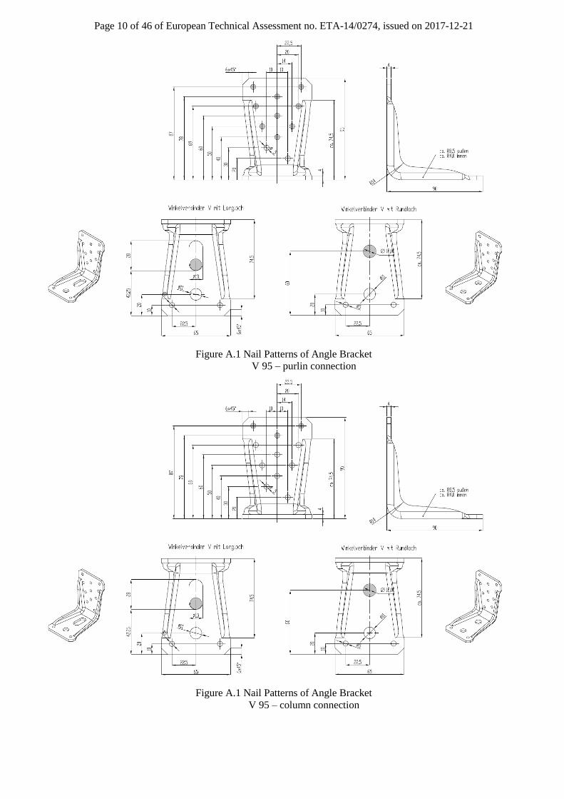
Page 17 of 46 of European Technical Assessment no. ETA-14/0274, issued on 2017-12-21
Table B.6: Characteristic values in the F2 for V 95, 1 angle bracket / connection
V 95
F2,Rk in kN
H in m
B in m 0,12 0,14 0,18
0,06 4,29 4,58 4,68
0,10 3,72 3,81 3,98
0,14 3,56 3,61 3,70
Table B.7: Factor kt for angle bracket V 95 force F2
V 95
kt
H in m
B in m 0,12 0,14 0,18
0,06 2,16 2,24 2,44
0,10 2,05 2,08 2,15
0,14 2,01 2,03 2,07
Table B.8: Characteristic values F2 for V 135, 1 angle bracket / connection
V 135
F2,Rk in kN
H in m
B in m 0,16 0,18 0,22
0,06 4,45 4,94 5,03
0,10 3,91 3,98 4,06
0,14 3,73 3,77 3,83
Table B.9: Factor kt for angle bracket V 135 force 2
V 135
kt
H in m
B in m 0,16 0,18 0,22
0,06 1,94 2,82 4,50
0,10 2,02 2,06 2,04
0,14 1,94 1,97 2,02

Page 18 of 46 of European Technical Assessment no. ETA-14/0274, issued on 2017-12-21
Table B.10: Characteristic values F2 for V-MH 137, 1 angle bracket / connection
V-MH 137
F2,Rk in kN
H in m
B in m 0,16 0,18 0,22
0,06 3,83 3,73 3,95
0,10 3,45 3,55 3,71
0,14 3,71 3,34 3,44
Table B.11: Factor kt for angle bracket V-MH 137 force 2
V-MH 137
kt
H in m
B in m 0,16 0,18 0,22
0,06 1,70 1,73 2,04
0,10 1,61 1,63 1,65
0,14 1,65 1,59 1,61
Table B.12: Characteristic values F3 for V 95, 1 angle bracket / connection
V 95
H in m F3,Rk in kN
Steel Timber
0,12 1,15 2,06
0,14 0,90 1,35
0,18 0,62 0,79
Table B.13: Characteristic values F3 for V 135, 1 angle bracket / connection
V 135
H in m F3,Rk in kN
Steel
0,16 1,24
0,18 0,94
0,22 0,48
Table B.14: Characteristic values F3 for V-MH 137, 1 angle bracket / connection
V-MH 137
H in m F3,Rk in kN
Steel
0,16 0,65
0,18 0,53
0,22 0,38

Page 19 of 46 of European Technical Assessment no. ETA-14/0274, issued on 2017-12-21
Figure B.3 Load F2 (left) and Load F3 (right)
Table B.15: Characteristic values for Force F4/F5
Angle Bracket F4/5,Rk in kN
V 95 7,58
V 135 7,99
V-MH 137 8,57
For different purlin widths and depths, the interaction equations were evaluated. The results are given in the
tables 15 and 16.
Table B.16: Characteristic values F4/F5 for V 95
V 95
F4,5Rk in kN
H in m
B in m 0,12 0,14 0,18
0,06 6,63 6,37 5,83
0,10 7,19 7,07 6,79
0,14 7,38 7,31 7,14
Table B.17: Characteristic values F4/F5 for V 135
V 135
F4/5,Rk in kN
H in m
B in m 0,16 0,18 0,22
0,06 7,14 6,96 6,57
0,10 7,65 7,57 7,38
0,14 7,81 7,77 7,66

Page 20 of 46 of European Technical Assessment no. ETA-14/0274, issued on 2017-12-21
Figure B.4 Load Case F4/F5 reduced to two basic load cases
Table B.18: Characteristic values F6 (1 angle bracket / connection) and F7 (2 angle brackets / connection)
Angle Bracket F6,Rk in kN F7,Rk in kN
V 95 1,72 3,44
V 135 2,76 5,53
V-MH 137 2,14 4,28

Page 21 of 46 of European Technical Assessment no. ETA-14/0274, issued on 2017-12-21
Angle brackets Concrete flat steel anchor
Support conditions
The distance between the timber elements and the concrete member in the area of the connection must not exceed
3 mm.
Fastener specification
The holes have to be nailed as given in Annex A, beginning at the end of the timber-concrete steel anchor.
The number constitutes at least 4 and follows from the static calculation.
Wane
Wane is not allowed; the timber-concrete steel anchor must seat solidly on timber.
Characteristic load-carrying capacities for connections with one timber-concrete steel anchor per
connection
Table B.1: Characteristic load-carrying capacities Load F1 – per timber-concrete steel anchor
Type Timber (FRk,N) Steel Transverse tensile
failure Bending (FRk,m) Tension (FRk,t)
2,0 mm 1,62 kN per nail 3,33 kN 17,8 kN See chapter 3
4,0 mm 1,56 kN per nail 9,07 kN 35,6 kN See chapter 3
Steel failure in bending is governing for timber-concrete steel anchors which are fixed with bolts and washers 43
mm x 4 mm. Steel failure in tension is governing for cast in concrete timber-concrete steel anchors.
Splitting
For a lifting force F1 splitting has to be proved, when necessary, for the timber element. The capacity of a
connection with timber-concrete steel anchors is calculated according to the general splitting design for
connections with mechanical fasteners in EN 1995:2004.
e90,Rk
e
hF 14 b
h1
h
(B.1)
Where:
F90,Rk the characteristic splitting capacity in N
b the member thickness, in mm
he is the loaded edge distance to the centre of the most distant fastener in mm
h the timber member height in mm
The design value of the force component perpendicular to the structural member’s axis F90,Ed has to be lower than
the design capacity F90,Rd.
Single Angle Bracket

Page 22 of 46 of European Technical Assessment no. ETA-14/0274, issued on 2017-12-21
Würth Hold downs
Figure B.1 Dimensions of type V Plus 460x90x65x3,0

Page 23 of 46 of European Technical Assessment no. ETA-14/0274, issued on 2017-12-21
Figure B.2 Dimensions of type V Plus 460x90x65x4,0

Page 24 of 46 of European Technical Assessment no. ETA-14/0274, issued on 2017-12-21
Figure B.3 Dimensions of type V PLus 560x90x65x3,0

Page 25 of 46 of European Technical Assessment no. ETA-14/0274, issued on 2017-12-21
Figure B.4 Dimensions of type V Plus 560x90x65x4,0

Page 26 of 46 of European Technical Assessment no. ETA-14/0274, issued on 2017-12-21
Figure B.5 Dimensions of type HTA 340x60x60x3,0
Figure B.6 Dimensions of type HTA 440x60x60x3,0

Page 27 of 46 of European Technical Assessment no. ETA-14/0274, issued on 2017-12-21
Figure B.7 Dimensions of type HTA 540x60x60x3,0
Figure B.8 Dimensions of type HTA 620x80x80x3,0

Page 28 of 46 of European Technical Assessment no. ETA-14/0274, issued on 2017-12-21
Figure B.9 Dimensions of base plates type HTA Lx60x60x3,0 (left) and HTA Lx80x80x3,0 (right)
Figure B.10 Typical installation

Page 29 of 46 of European Technical Assessment no. ETA-14/0274, issued on 2017-12-21
Angle Brackets

Page 30 of 46 of European Technical Assessment no. ETA-14/0274, issued on 2017-12-21

Page 31 of 46 of European Technical Assessment no. ETA-14/0274, issued on 2017-12-21

Page 32 of 46 of European Technical Assessment no. ETA-14/0274, issued on 2017-12-21

Page 33 of 46 of European Technical Assessment no. ETA-14/0274, issued on 2017-12-21

Page 34 of 46 of European Technical Assessment no. ETA-14/0274, issued on 2017-12-21

Page 35 of 46 of European Technical Assessment no. ETA-14/0274, issued on 2017-12-21

Page 36 of 46 of European Technical Assessment no. ETA-14/0274, issued on 2017-12-21

Page 37 of 46 of European Technical Assessment no. ETA-14/0274, issued on 2017-12-21

Page 38 of 46 of European Technical Assessment no. ETA-14/0274, issued on 2017-12-21

Page 39 of 46 of European Technical Assessment no. ETA-14/0274, issued on 2017-12-21
Concrete flat steel anchors

Page 40 of 46 of European Technical Assessment no. ETA-14/0274, issued on 2017-12-21
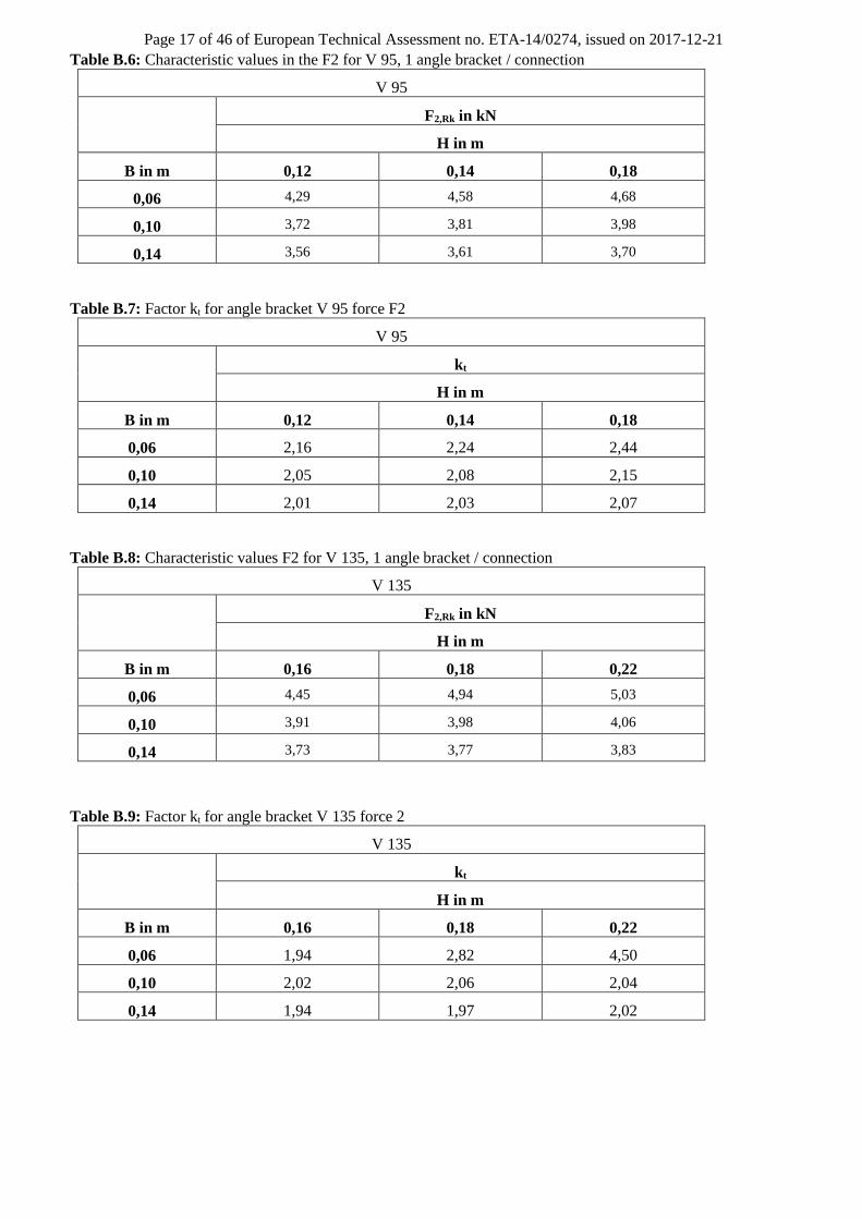
Page 41 of 46 of European Technical Assessment no. ETA-14/0274, issued on 2017-12-21

Page 42 of 46 of European Technical Assessment no. ETA-14/0274, issued on 2017-12-21

Page 43 of 46 of European Technical Assessment no. ETA-14/0274, issued on 2017-12-21

Page 44 of 46 of European Technical Assessment no. ETA-14/0274, issued on 2017-12-21

Page 45 of 46 of European Technical Assessment no. ETA-14/0274, issued on 2017-12-21

Page 46 of 46 of European Technical Assessment no. ETA-14/0274, issued on 2017-12-21