Embed Size (px)
Citation preview
ETA-Danmark A/S Göteborg Plads 1 DK-2150 Nordhavn Tel. +45 72 24 59 00 Fax +45 72 24 59 04 Internet www.etadanmark.dk
Authorised and notified according to Article 29 of the Regulation (EU) No 305/2011 of the European Parliament and of the Council of 9 March 2011
MEMBER OF EOTA
European Technical Assessment ETA-13/0760 of 2018/04/12
I General Part
Technical Assessment Body issuing the ETA and designated according to Article 29 of the Regulation (EU) No 305/2011: ETA-Danmark A/S
Trade name of the construction product:
Arras Construction Furniture Post Bases
Product family to which the above construction product belongs:
Three-dimensional nailing plate (Post bases for the support of timber columns and posts as load-bearing elements)
Manufacturer: Arras Construction Furniture OÜ Veerme 23 EST-11625 Talinn Tel. + 372 670 6000 Fax + 372 670 6405
Internet www.arrascf.eu Manufacturing plant: Arras Construction Furniture OÜ
Veerme 23 EST- 11625 Talinn
This European Technical Assessment contains:
16 pages including 2 annexes which form an integral part of the document
This European Technical Assessment is issued in accordance with Regulation (EU) No 305/2011, on the basis of:
Guideline for European Technical Approval (ETAG) No. 015 Three-Dimensional Nailing Plates, April 2013, used as European Assessment Document (EAD).
This version replaces:
The ETA with the same number issued on 2013-06-19 and expiry on 2018-06-19
Page 2 of 16 of European Technical Assessment no. ETA-13/0760, issued on 2018-04-12
Translations of this European Technical Assessment in
other languages shall fully correspond to the original
issued document and should be identified as such.
Communication of this European Technical
Assessment, including transmission by electronic
means, shall be in full (excepted the confidential
Annex(es) referred to above). However, partial
reproduction may be made, with the written consent of
the issuing Technical Assessment Body. Any partial
reproduction must be identified as such.
Page 3 of 16 of European Technical Assessment no. ETA-13/0760, issued on 2018-04-12
II
SPECIFIC PART OF THE
EUROPEAN TECHNICAL
ASSESSMENT
1 Technical description of product and
intended use
Technical description of the product
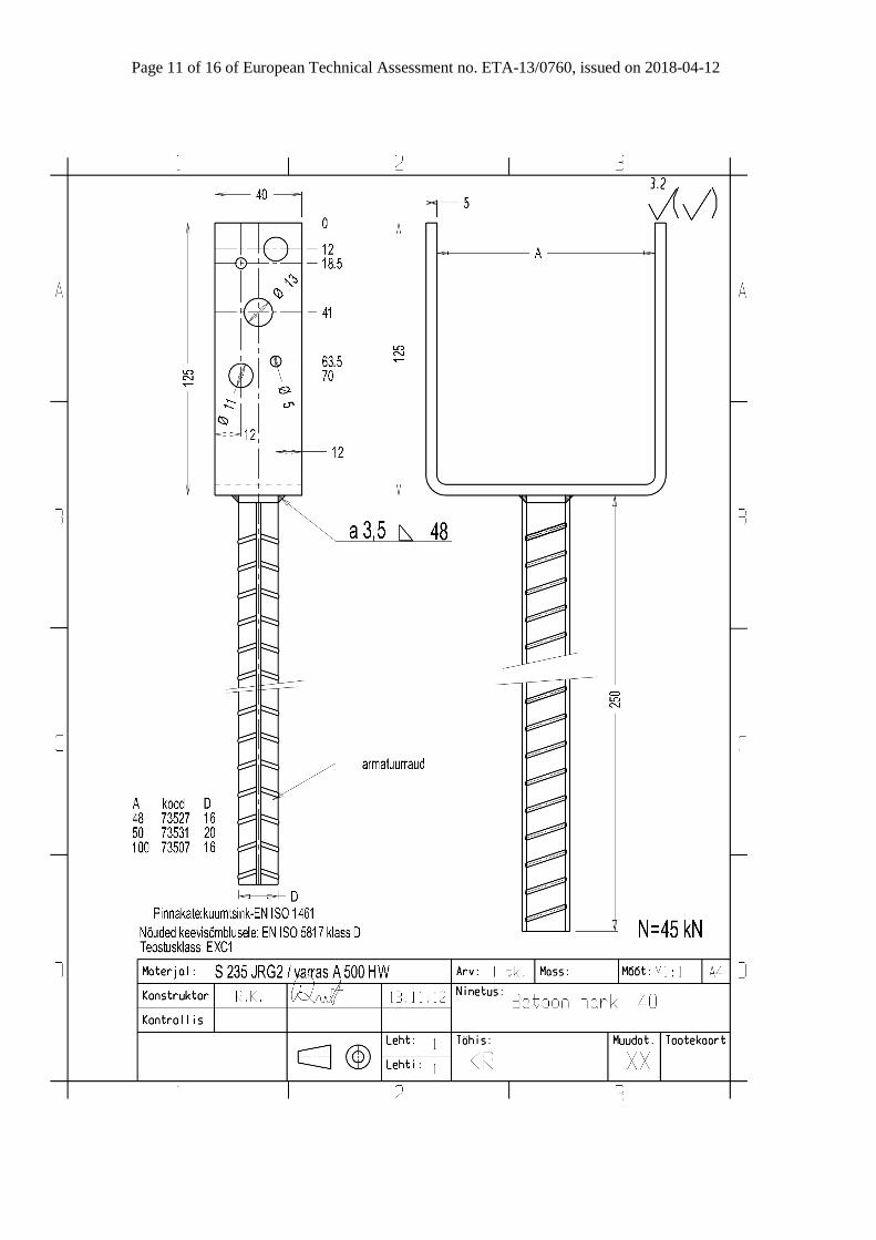
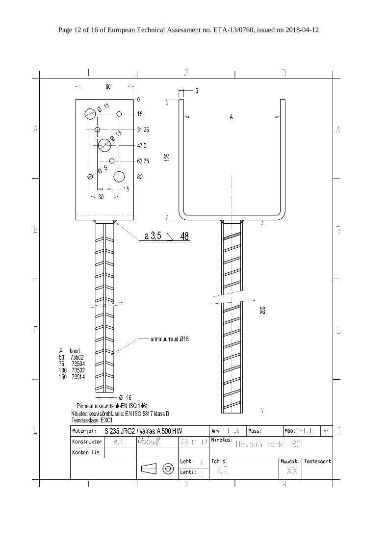
The post bases are made of 5.0 mm thick steel plates in
combination with reinforcing bars. The post bases are
produced from steel grade S235JR according to EN
10025-2:2005-04 with minimum characteristic yield
strength of ReH = 235 N/mm² and minimum
characteristic tensile strength of Rm = 360 N/mm². The
reinforcing bars are produced from steel grade BST
500 S(A) according to EN 10080:2005-08 with
minimum characteristic yield strength of ReH = 500
N/mm².
For the connections with metal fasteners bolts ø12 mm
(4.6) or dowels ø12 mm (S235), screws ø10x60 mm
and nails ø4x40 mm according to EN 14592 or
according to a European technical approval are used.
The screws shall be driven into pre-drilled holes
according to EN 1995-1-1, 10.4.5 or according to the
ETA of the screws, respectively.
Dimensions are shown in Annex A and B.
2 Specification of the intended use in
accordance with the applicable EAD
The intended use of the post bases is the support of
timber columns and posts as load-bearing elements,
where requirements for mechanical resistance and
stability and safety in use in the sense of the Basic
Works Requirements 1 and 4 of Regulation (EU)
305/2011 shall be fulfilled.
The static and kinematical behaviour of the timber
members or the supports shall be as described in Annex
B.
The timber posts may be of solid timber of strength
class C24 or better according to EN 338:2003-09.
Minimum dimensions for the post must be considered
(Annex A).
The post base shall be installed as pictured in the
drawings. The cross-section of the timber column shall
be positioned centrically and with the end grain plane on
the base plate.
The maximum distance between the foundation and the
base plate of the post base is given in Annex A, table
A.1.
Annex B states the load-carrying capacities of the post
bases for solid timber of strength class C24 according
to EN 338:2003-09. The design of the connections shall
be in accordance with Eurocode 3 and Eurocode 5 or a
similar national code. The anchorage of the post base in
the foundation and imperfections exceeding the
assumptions in Eurocode 5, 5.4.4 are not part of this
ETA.
The post bases are for use in timber structures subject to
the service classes 1, 2 and 3 of Eurocode 5 and for
connections subject to static or quasi-static loading.
The scope of the post bases regarding resistance to
corrosion shall be defined according to national
provisions that apply at the installation site considering
environmental conditions.
Section 3.11 of this ETA contains the corrosion
protection for Arras CF post bases made from carbon
steel.
The provisions made in this European Technical
Assessment are based on an assumed intended working
life of the connectors of 50 years.
The indications given on the working life cannot be
interpreted as a guarantee given by the producer or
Assessment Body, but are to be regarded only as a
means for choosing the right products in relation to the
expected economically reasonable working life of the
works.
Page 4 of 16 of European Technical Assessment no. ETA-13/0760, issued on 2018-04-12
3 Performance of the product and references to the methods used for its assessment
ETAG paragraph
Characteristic
Assessment of characteristic
2.1 Mechanical resistance and stability*)
6.1.1
Characteristic load-carrying capacity
See Annex B
6.1.2
Stiffness
No performance assessed
6.1.3
Ductility in cyclic testing
No performance assessed
2.2 Safety in case of fire
6.2.1
Reaction to fire
The post bases are made from steel classified
as Euroclass A1 in accordance with EN
13501-1 and European Commission
Delegated Regulation 2016/364 of 1 July
2015
2.3 Hygiene, health and the environment
6.3.1
Influence on air quality
No dangerous materials **)
2.4 Safety in use
Not relevant
2.5 Protection against noise
Not relevant
2.6 Energy economy and heat retention
Not relevant
2.7 Related aspects of serviceability
6.7.1
Durability
The post bases have been assessed as having
satisfactory durability and serviceability when
used in timber structures using the timber
species described in Eurocode 5 and subject to
the conditions defined by service class 1, 2
and 3
6.7.2
Serviceability
6.7.3
Identification
See Annex A
*) See additional information in section 3.9 – 3.12.
**) In addition to the specific clauses relating to dangerous substances contained in this European Technical
Assessment, there may be other requirements applicable to the products falling within its scope (e.g. transposed
European legislation and national laws, regulations and administrative provisions). To meet the provisions of the
Construction Products Regulation, these requirements need also to be complied with, when and where they apply.
Page 5 of 16 of European Technical Assessment no. ETA-13/0760, issued on 2018-04-12
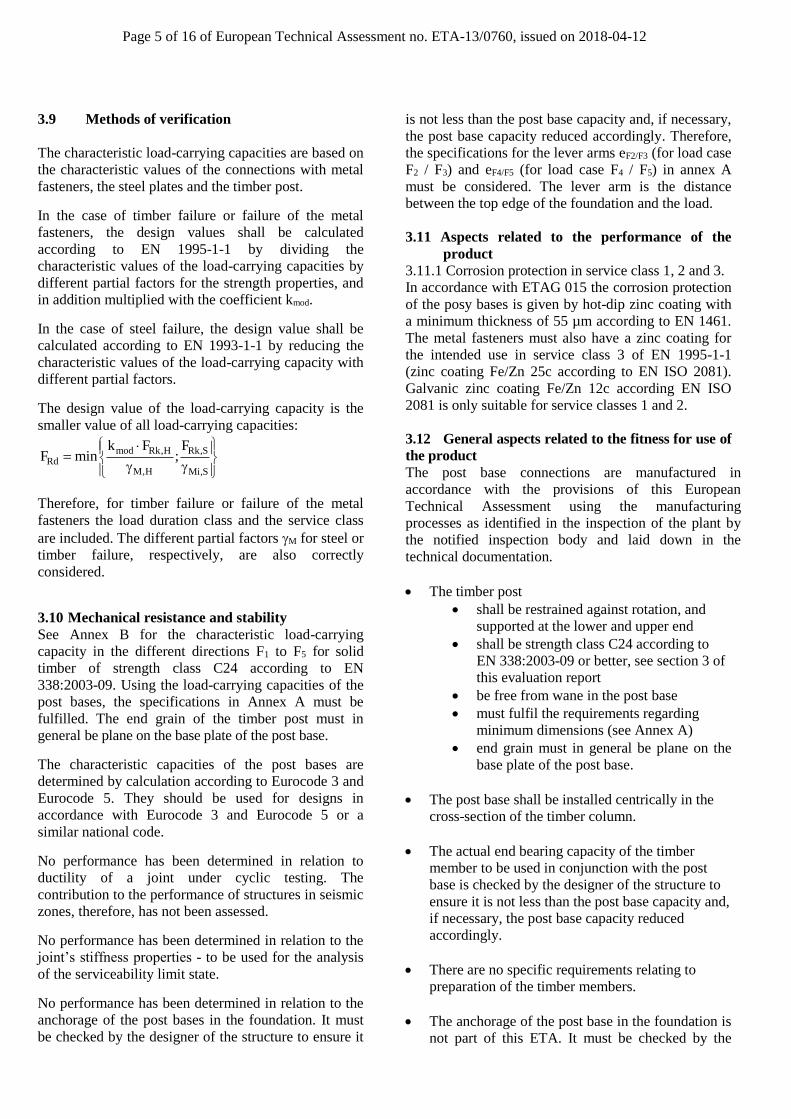
3.9 Methods of verification
The characteristic load-carrying capacities are based on
the characteristic values of the connections with metal
fasteners, the steel plates and the timber post.
In the case of timber failure or failure of the metal
fasteners, the design values shall be calculated
according to EN 1995-1-1 by dividing the
characteristic values of the load-carrying capacities by
different partial factors for the strength properties, and
in addition multiplied with the coefficient kmod.
In the case of steel failure, the design value shall be
calculated according to EN 1993-1-1 by reducing the
characteristic values of the load-carrying capacity with
different partial factors.
The design value of the load-carrying capacity is the
smaller value of all load-carrying capacities:
mod Rk,H Rk,SRd
M,H Mi,S
k F FF min ;
Therefore, for timber failure or failure of the metal
fasteners the load duration class and the service class
are included. The different partial factors M for steel or
timber failure, respectively, are also correctly
considered.
3.10 Mechanical resistance and stability
See Annex B for the characteristic load-carrying
capacity in the different directions F1 to F5 for solid
timber of strength class C24 according to EN
338:2003-09. Using the load-carrying capacities of the
post bases, the specifications in Annex A must be
fulfilled. The end grain of the timber post must in
general be plane on the base plate of the post base.
The characteristic capacities of the post bases are
determined by calculation according to Eurocode 3 and
Eurocode 5. They should be used for designs in
accordance with Eurocode 3 and Eurocode 5 or a
similar national code.
No performance has been determined in relation to
ductility of a joint under cyclic testing. The
contribution to the performance of structures in seismic
zones, therefore, has not been assessed.
No performance has been determined in relation to the
joint’s stiffness properties - to be used for the analysis
of the serviceability limit state.
No performance has been determined in relation to the
anchorage of the post bases in the foundation. It must
be checked by the designer of the structure to ensure it
is not less than the post base capacity and, if necessary,
the post base capacity reduced accordingly. Therefore,
the specifications for the lever arms eF2/F3 (for load case
F2 / F3) and eF4/F5 (for load case F4 / F5) in annex A
must be considered. The lever arm is the distance
between the top edge of the foundation and the load.
3.11 Aspects related to the performance of the
product
3.11.1 Corrosion protection in service class 1, 2 and 3.
In accordance with ETAG 015 the corrosion protection
of the posy bases is given by hot-dip zinc coating with
a minimum thickness of 55 µm according to EN 1461.
The metal fasteners must also have a zinc coating for
the intended use in service class 3 of EN 1995-1-1
(zinc coating Fe/Zn 25c according to EN ISO 2081).
Galvanic zinc coating Fe/Zn 12c according EN ISO
2081 is only suitable for service classes 1 and 2.
3.12 General aspects related to the fitness for use of
the product
The post base connections are manufactured in
accordance with the provisions of this European
Technical Assessment using the manufacturing
processes as identified in the inspection of the plant by
the notified inspection body and laid down in the
technical documentation.
• The timber post
• shall be restrained against rotation, and
supported at the lower and upper end
• shall be strength class C24 according to
EN 338:2003-09 or better, see section 3 of
this evaluation report
• be free from wane in the post base
• must fulfil the requirements regarding
minimum dimensions (see Annex A)
• end grain must in general be plane on the
base plate of the post base.
• The post base shall be installed centrically in the
cross-section of the timber column.
• The actual end bearing capacity of the timber
member to be used in conjunction with the post
base is checked by the designer of the structure to
ensure it is not less than the post base capacity and,
if necessary, the post base capacity reduced
accordingly.
• There are no specific requirements relating to
preparation of the timber members.
• The anchorage of the post base in the foundation is
not part of this ETA. It must be checked by the
Page 6 of 16 of European Technical Assessment no. ETA-13/0760, issued on 2018-04-12
designer of the structure to ensure it is not less than
the post base capacity and, if necessary, the post
base capacity reduced accordingly. Therefore, the
specifications for the lever arms eF2/F3 (for load
case F2 / F3) and eF4/F5 (for load case F4 / F5) in
Annex A must be considered. The lever arm is the
distance between the top edge of the foundation
and the load.
• Nails, screws and bolts or dowels are alternative
fastening variations. The minimum number of
fasteners per fastening variation is given. Fastener
holes shall be filled beginning at the top edge of
the post base corresponding to their diameter (hole
diameter Ø 5 mm for nails, Ø 11 mm for screws, Ø
13 mm for bolts/dowels).
• The execution of the connection shall be in
accordance with the approval holder’s technical
literature
Page 7 of 16 of European Technical Assessment no. ETA-13/0760, issued on 2018-04-12
4 Attestation and verification of
constancy of performance (AVCP)
4.1 AVCP system
According to the decision 97/638/EC of the European
Commission1, as amended, the system(s) of
assessment and verification of constancy of
performance (see Annex V to Regulation (EU) No
305/2011) is 2+.
5 Technical details necessary for the
implementation of the AVCP system, as
foreseen in the applicable EAD
Technical details necessary for the implementation of
the AVCP system are laid down in the control plan
deposited at ETA-Danmark prior to CE marking.
Issued in Copenhagen on 2018-04-12 by
Thomas Bruun
Managing Director, ETA-Danmark
Page 8 of 16 of European Technical Assessment no. ETA-13/0760, issued on 2018-04-12
Annex A
Product details and definitions
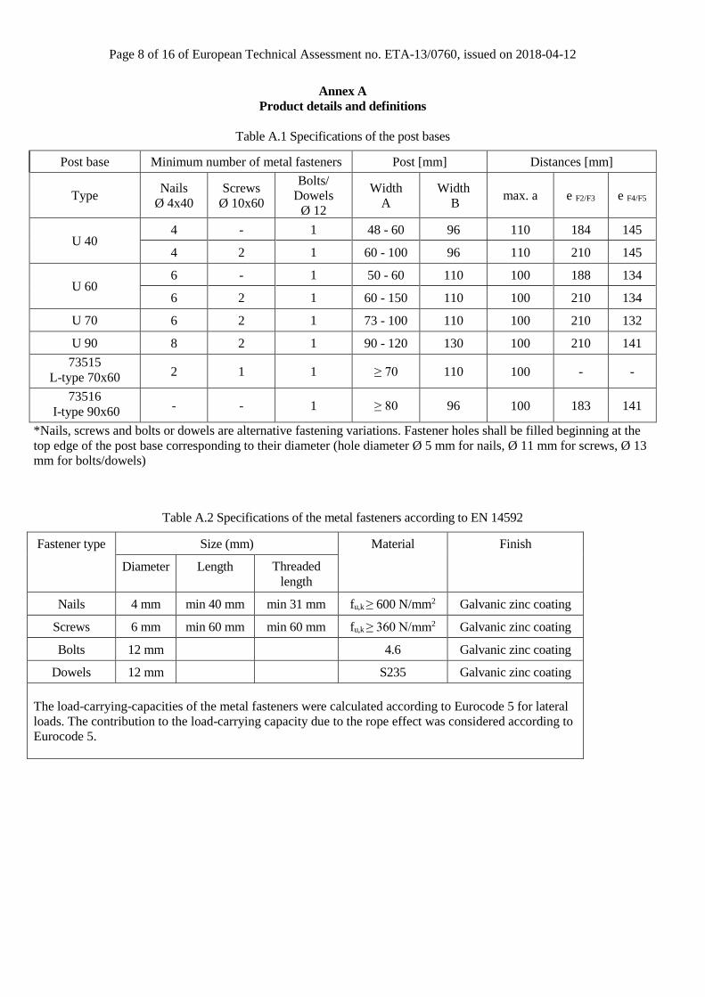
Table A.1 Specifications of the post bases
Post base Minimum number of metal fasteners Post [mm] Distances [mm]
Type Nails
Ø 4x40
Screws
Ø 10x60
Bolts/
Dowels
Ø 12
Width
A
Width
B max. a e F2/F3 e F4/F5
U 40 4 - 1 48 - 60 96 110 184 145
4 2 1 60 - 100 96 110 210 145
U 60 6 - 1 50 - 60 110 100 188 134
6 2 1 60 - 150 110 100 210 134
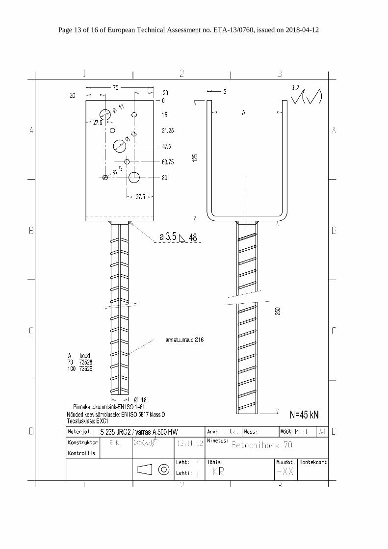
U 70 6 2 1 73 - 100 110 100 210 132
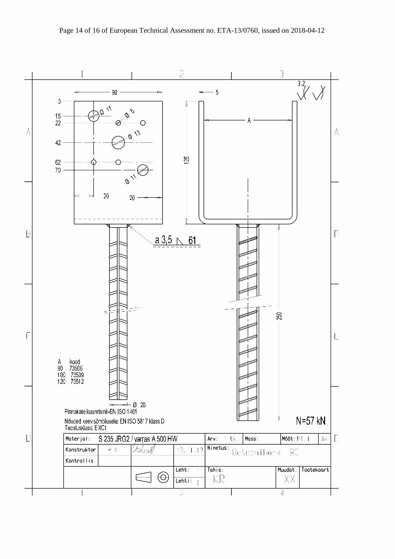
U 90 8 2 1 90 - 120 130 100 210 141
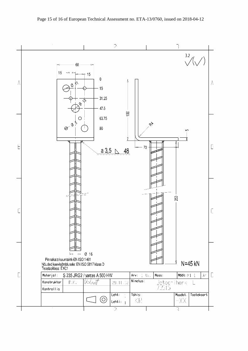
73515
L-type 70x60 2 1 1 ≥ 70 110 100 - -
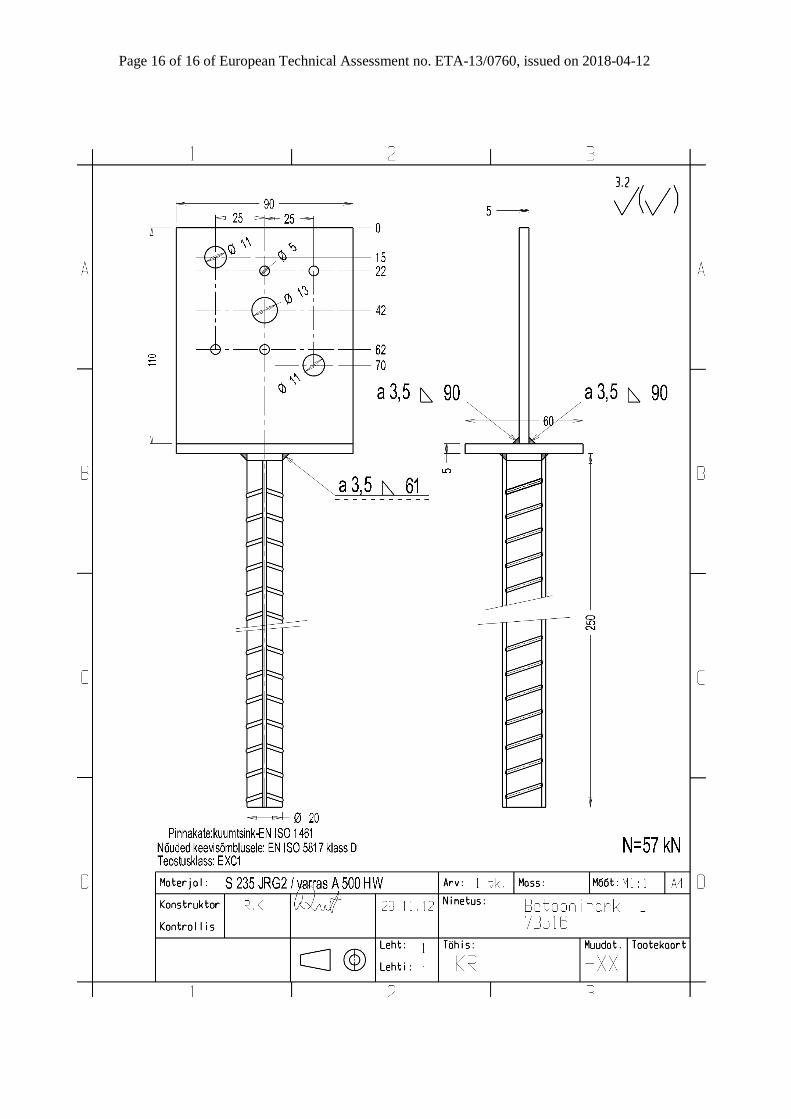
73516
I-type 90x60 - - 1 ≥ 80 96 100 183 141
*Nails, screws and bolts or dowels are alternative fastening variations. Fastener holes shall be filled beginning at the
top edge of the post base corresponding to their diameter (hole diameter Ø 5 mm for nails, Ø 11 mm for screws, Ø 13
mm for bolts/dowels)
Table A.2 Specifications of the metal fasteners according to EN 14592
Fastener type
Size (mm) Material Finish
Diameter Length Threaded
length
Nails 4 mm min 40 mm min 31 mm fu,k ≥ 600 N/mm2 Galvanic zinc coating
Screws 6 mm min 60 mm min 60 mm fu,k ≥ 360 N/mm2 Galvanic zinc coating
Bolts 12 mm 4.6 Galvanic zinc coating
Dowels 12 mm S235 Galvanic zinc coating
The load-carrying-capacities of the metal fasteners were calculated according to Eurocode 5 for lateral
loads. The contribution to the load-carrying capacity due to the rope effect was considered according to
Eurocode 5.
Page 9 of 16 of European Technical Assessment no. ETA-13/0760, issued on 2018-04-12
Annex B
Characteristic load-carrying capacities
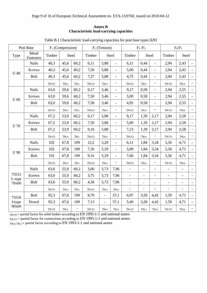
Table B.1 Characteristic load-carrying capacities for post base types [kN]
Post Base F1 (Compression) F1 (Tension) F2 /F3 F4/F5
Type Metal
Fasteners Timber Steel Timber Steel Timber Steel Timber Steel
U 40
Nails 40,3 45,6 60,2 6,11 5,88 - 6,11 0,44 - 2,94 2,43 -
Screws 40,3 45,6 60,2 7,50 5,88 - 5,00 0,44 - 2,94 2,43 -
Bolt 40,3 45,6 60,2 7,27 5,88 - 4,75 0,44 - 2,94 2,43 -
M (T) M,0 M,1 M (C) M,0 - M (C) M,0 - M (T) M,0 -
U 60
Nails 63,0 59,6 60,2 9,17 3,46 - 9,17 0,58 - 2,94 2,55 -
Screws 63,0 59,6 60,2 7,50 3,46 - 5,00 0,58 - 2,94 2,55 -
Bolt 63,0 59,6 60,2 7,58 3,46 - 4,95 0,58 - 2,94 2,55 -
M (T) M,0 M,1 M (C) M,0 - M (C) M,0 - M (T) M,0 -
U 70
Nails 67,2 53,9 60,2 9,17 5,88 - 9,17 1,39 2,17 2,94 2,58 -
Screws 67,2 53,9 60,2 7,50 5,88 - 5,00 1,39 2,17 2,94 2,58 -
Bolt 67,2 53,9 60,2 9,16 5,88 - 7,23 1,39 2,17 2,94 2,58 -
M (T) M,0 M,1 M (C) M,0 - M (C) M,0 - M (T) M,0 -
U 90
Nails 102 67,8 109 12,2 5,29 - 6,11 1,84 3,34 5,56 4,71 -
Screws 102 67,8 109 7,50 5,29 - 5,00 1,84 3,34 5,56 4,71 -
Bolt 102 67,8 109 9,16 5,29 - 7,66 1,84 3,34 5,56 4,71 -
M (T) M,0 M,1 M (C) M,0 - M (C) M,0 - M (T) M,0 -
73515
L-type
70x60
Nails 63,6 55,9 60,2 3,06 5,73 7,96 - - - - - -
Screws 63,6 55,9 60,2 3,75 5,73 7,96 - - - - - -
Bolt 63,6 55,9 60,2 4,58 5,73 7,96 - - - - - -
M (T) M,0 M,1 M (C) M,0 M,2 - - - - - -
73516
I-type
90x60
Bolt 92,3 67,6 109 8,70 - 57,1 6,97 3,28 4,42 1,59 4,71 -
Dowel 92,3 67,6 109 7,13 - 57,1 5,40 3,28 4,42 1,59 4,71 -
M (T) M,0 - M (C) M,0 M,2 M (C) M,0 M,2 M (T) M,0 -
M (T) = partial factor for solid timber according to EN 1995-1-1 and national annex
M (C) = partial factor for connections according to EN 1995-1-1 and national annex
M,0; M,1 = partial factor according to EN 1993-1-1 and national annex
Page 10 of 16 of European Technical Assessment no. ETA-13/0760, issued on 2018-04-12
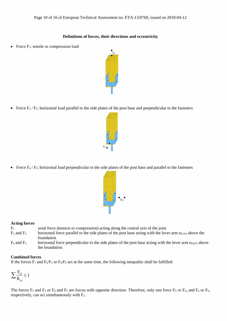
Definitions of forces, their directions and eccentricity
• Force F1: tensile or compression load
F1
• Force F2 / F3: horizontal load parallel to the side plates of the post base and perpendicular to the fasteners
F23
• Force F4 / F5: horizontal load perpendicular to the side plates of the post base and parallel to the fasteners
F45
Acting forces
F1 axial force (tension or compression) acting along the central axis of the joint
F2 and F3 horizontal force parallel to the side plates of the post base acting with the lever arm eF2/F3 above the
foundation
F4 and F5 horizontal force perpendicular to the side plates of the post base acting with the lever arm eF4/F5 above
the foundation
Combined forces
If the forces F1 and F2/F3 or F4/F5 act at the same time, the following inequality shall be fulfilled:
i,d
i,d
F1
R
The forces F2 and F3 or F4 and F5 are forces with opposite direction. Therefore, only one force F2 or F3, and F4 or F5,
respectively, can act simultaneously with F1.
Page 11 of 16 of European Technical Assessment no. ETA-13/0760, issued on 2018-04-12
Page 12 of 16 of European Technical Assessment no. ETA-13/0760, issued on 2018-04-12
Page 13 of 16 of European Technical Assessment no. ETA-13/0760, issued on 2018-04-12
Page 14 of 16 of European Technical Assessment no. ETA-13/0760, issued on 2018-04-12
Page 15 of 16 of European Technical Assessment no. ETA-13/0760, issued on 2018-04-12
Page 16 of 16 of European Technical Assessment no. ETA-13/0760, issued on 2018-04-12