Embed Size (px)
Citation preview

Diese Zulassung umfasst
This Approval contains
17 Seiten einschließlich 7 Anhänge 17 pages including 7 annexes
E u r o p ä i s c h e O r g a n i s a t i o n f ü r T e c h n i s c h e Z u l a s s u n g e n
E u r o p e a n O r g a n i s a t i o n f o r T e c h n i c a l A p p r o v a l s
Z45216.13 8.06.04-348/12
English translation prepared by DIBt - Original version in German language
Handelsbezeichnung Trade name
Dämmstoffdübel KOELNER TFIX-8P
Insulation support KOELNER TFIX-8P
Zulassungsinhaber
Holder of approval RAWLPLUG S.A. Kwidzynska 6 51-416 WROCLAW POLEN
Zulassungsgegenstand und Verwendungszweck
Schlagdübel zur Befestigung von außenseitigen Wärmedämm- Verbundsystemen mit Putzschicht in Beton und Mauerwerk
Generic type and use of construction product
Nailed-in plastic anchor for fixing of external thermal insulation composite systems with rendering in concrete and masonry
Geltungsdauer:
Validity: vom from
27 June 2013
bis to
27 June 2018
Herstellwerk
Manufacturing plant RAWLPLUG S.A. Kwidzynska 6 51-416 WROCLAW POLEN
European Technical Approval ETA-13/0845
Ele
ctro
nic
copy
of t
he E
TA b
y D
IBt:
ETA
-13/
0845

European technical approval ETA-13/0845 English translation prepared by DIBt
Page 2 of 17 | 27 June 2013
Z45216.13 8.06.04-348/12
I LEGAL BASES AND GENERAL CONDITIONS
1 This European technical approval is issued by Deutsches Institut für Bautechnik in accordance with:
- Council Directive 89/106/EEC of 21 December 1988 on the approximation of laws, regulations and administrative provisions of Member States relating to construction products1, modified by Council Directive 93/68/EEC2 and Regulation (EC) N° 1882/2003 of the European Parliament and of the Council3;
- Gesetz über das In-Verkehr-Bringen von und den freien Warenverkehr mit Bauprodukten zur Umsetzung der Richtlinie 89/106/EWG des Rates vom 21. Dezember 1988 zur Angleichung der Rechts- und Verwaltungsvorschriften der Mitgliedstaaten über Bauprodukte und anderer Rechtsakte der Europäischen Gemeinschaften (Bauproduktengesetz - BauPG) vom 28. April 19984, as amended by Article 2 of the law of 8 November 20115;
- Common Procedural Rules for Requesting, Preparing and the Granting of European technical approvals set out in the Annex to Commission Decision 94/23/EC6;
- Guideline for European technical approval of "Plastic anchors for fixing of external thermal insulation composite systems with rendering", ETAG 014.
2 Deutsches Institut für Bautechnik is authorized to check whether the provisions of this European technical approval are met. Checking may take place in the manufacturing plant. Nevertheless, the responsibility for the conformity of the products to the European technical approval and for their fitness for the intended use remains with the holder of the European technical approval.
3 This European technical approval is not to be transferred to manufacturers or agents of manufacturers other than those indicated on page 1, or manufacturing plants other than those indicated on page 1 of this European technical approval.
4 This European technical approval may be withdrawn by Deutsches Institut für Bautechnik, in particular pursuant to information by the Commission according to Article 5(1) of Council Directive 89/106/EEC.
5 Reproduction of this European technical approval including transmission by electronic means shall be in full. However, partial reproduction can be made with the written consent of Deutsches Institut für Bautechnik. In this case partial reproduction has to be designated as such. Texts and drawings of advertising brochures shall not contradict or misuse the European technical approval.
6 The European technical approval is issued by the approval body in its official language. This version corresponds fully to the version circulated within EOTA. Translations into other languages have to be designated as such.
1 Official Journal of the European Communities L 40, 11 February 1989, p. 12
2 Official Journal of the European Communities L 220, 30 August 1993, p. 1
3 Official Journal of the European Union L 284, 31 October 2003, p. 25
4 Bundesgesetzblatt Teil I 1998, p. 812
5 Bundesgesetzblatt Teil I 2011, p. 2178
6 Official Journal of the European Communities L 17, 20 January 1994, p. 34
Ele
ctro
nic
copy
of t
he E
TA b
y D
IBt:
ETA
-13/
0845

European technical approval ETA-13/0845 English translation prepared by DIBt
Page 3 of 17 | 27 June 2013
Z45216.13 8.06.04-348/12
II SPECIFIC CONDITIONS OF THE EUROPEAN TECHNICAL APPROVAL
1 Definition of product/ products and intended use
1.1 Definition of the construction product
The KOELNER insulation support TFIX-8P is a nailed-in anchor which consists of a plastic part made of polypropylene and an accompanying specific nail of galvanised steel. The head of the nail has an additional plastic coating.
The anchor may in addition be combined with the anchor plates KWL 90, KWL 110 and KWL 140.
The installed anchor is shown in Annex 1.
1.2 Intended use
The anchor is intended to be used for anchorages for which requirements for safety in use in the sense of the Essential Requirement 4 of Council Directive 89/106/EEC shall be fulfilled and failure of anchorages made with these products would cause low risk to human life. The anchor is to be used only as multiple fixing for the anchorage of bonded thermal insulation composite systems (ETICS) according to ETAG 004 in concrete and masonry. The base material shall consist of reinforced or unreinforced normal weight concrete of strength class C12/15 at minimum and C50/60 at maximum according to EN 206-1:2000-12 and of masonry walls according to Annex 4, Table 4.
The anchor may only be used for transmission of wind suction loads and shall not be used for the transmission of dead loads of the thermal insulation composite system. The dead loads have to be transmitted by the bonding of the thermal insulation composite system.
The provisions made in this European technical approval are based on an assumed working life of the anchor of 25 years. The indications given on the working life cannot be interpreted as a guarantee given by the producer, but are to be regarded only as a means for choosing the right products in relation to the expected economically reasonable working life of the works.
2 Characteristics of the product and methods of verification
2.1 Characteristics of the product
The anchor corresponds to the drawings and information given in Annexes 2 and 3. The characteristic material values, dimensions and tolerances of the anchor not given in these Annexes shall correspond to the respective values laid down in the technical documentation7 of this European technical approval.
The characteristic values for the design of the anchorages are given in Annexes 4 and 5.
Each anchor is to be marked with the identifying mark, the type and the length of the anchor. The minimum effective anchorage depth shall be marked.
The anchor shall only be packaged and supplied as a complete unit.
7 The technical documentation of this European technical approval is deposited at the Deutsches Institut für Bautechnik
and, as far as relevant for the tasks of the approved bodies involved in the attestation of conformity procedure, is handed over to the approved bodies.
Ele
ctro
nic
copy
of t
he E
TA b
y D
IBt:
ETA
-13/
0845
European technical approval ETA-13/0845 English translation prepared by DIBt
Page 4 of 17 | 27 June 2013
Z45216.13 8.06.04-348/12
2.2 Methods of verification
The assessment of the fitness of the anchor for the intended use in relation to the requirements for safety in use in the sense of the Essential Requirement 4 has been made in compliance with
- the Guideline for European technical approval of "Plastic Anchors for Fixing of External Thermal Insulation Composite Systems with Rendering", ETAG 014, based on the use categories A, B, C, D and E,
- the EOTA Technical Report TR 025 "Determination of point thermal transmittance of plastic anchors for the anchorage of external thermal insulation composite systems (ETICS)" and
- the EOTA Technical Report TR 026 "Evaluation of plate stiffness from plastic anchors for fixing of external thermal insulation composite systems with rendering (ETICS)".
In addition to the specific clauses relating to dangerous substances contained in this European technical approval, there may be other requirements applicable to the products falling within its scope (e.g. transposed European legislation and national laws, regulations and administrative provisions). In order to meet the provisions of the Construction Products Directive, these requirements need also to be complied with, when and where they apply.
3 Evaluation and attestation of conformity and CE marking
3.1 System of attestation of conformity
According to the decision 97/463/EG of the European Commission8 the system 2(ii) (referred to as system 2+) of attestation of conformity applies.
This system of attestation of conformity is defined as follows.
System 2+: Declaration of conformity of the product by the manufacturer on the basis of:
(a) Tasks for the manufacturer:
(1) initial type-testing of the product; (2) factory production control; (3) testing of samples taken at the factory in accordance with a prescribed test plan.
(b) Tasks for the approved body:
(4) certification of factory production control on the basis of: – initial inspection of factory and of factory production control; – continuous surveillance, assessment and approval of factory production control.
3.2 Responsibilities
3.2.1 Tasks of the manufacturer
3.2.1.1 Factory production control
The manufacturer shall exercise permanent internal control of production. All the elements, requirements and provisions adopted by the manufacturer shall be documented in a systematic manner in the form of written policies and procedures, including records of results performed. This production control system shall insure that the product is in conformity with this European technical approval.
8 Official Journal of the European Communities L 198 of 25.07.1997.
Ele
ctro
nic
copy
of t
he E
TA b
y D
IBt:
ETA
-13/
0845

European technical approval ETA-13/0845 English translation prepared by DIBt
Page 5 of 17 | 27 June 2013
Z45216.13 8.06.04-348/12
The manufacturer may only use raw materials stated in the technical documentation of this European technical approval.
The factory production control shall be in accordance with the control plan which is part of the technical documentation of this European technical approval. The control plan is laid down in the context of the factory production control system operated by the manufacturer and deposited at Deutsches Institut für Bautechnik.9
The results of factory production control shall be recorded and evaluated in accordance with the provisions of the control plan.
3.2.1.2 Other tasks of manufacturer
The manufacturer shall, on the basis of a contract, involve a body which is approved for the tasks referred to in section 3.1 in the field of anchors in order to undertake the actions laid down in section 3.2.2. For this purpose, the control plan referred to in sections 3.2.1.1 and 3.2.2 shall be handed over by the manufacturer to the approved body involved.
The manufacturer shall make a declaration of conformity, stating that the construction product is in conformity with the provisions of this European technical approval.
3.2.2 Tasks of approved bodies
The approved body shall perform the
- initial inspection of factory and of factory production control,
- continuous surveillance, assessment and approval of factory production control,
in accordance with the provisions laid down in the control plan.
The approved body shall retain the essential points of its actions referred to above and state the results obtained and conclusions drawn in a written report.
The approved certification body involved by the manufacturer shall issue an EC certificate of conformity of the factory production control stating the conformity with the factory production control of this European technical approval.
In cases where the provisions of the European technical approval and its control plan are no longer fulfilled the certification body shall withdraw the certificate of conformity and inform Deutsches Institut für Bautechnik without delay.
3.3 CE marking
The CE marking shall be affixed on each packaging of the anchor. The letters "CE" shall be followed by the identification number of the approved certification body, where relevant, and be accompanied by the following additional information:
- the name and address of the producer (legal entity responsible for the manufacturer),
- the last two digits of the year in which the CE marking was affixed,
- the number of the EC certificate for the factory production control,
- the number of the European technical approval,
- the number of the guideline for European technical approval,
- use categories A, B, C, D and E.
9 The control plan is a confidential part of the documentation of the European technical approval, but not published
together with the ETA and only handed over to the approved body involved in the procedure of attestation of conformity. See section 3.2.2.
Ele
ctro
nic
copy
of t
he E
TA b
y D
IBt:
ETA
-13/
0845

European technical approval ETA-13/0845 English translation prepared by DIBt
Page 6 of 17 | 27 June 2013
Z45216.13 8.06.04-348/12
4 Assumptions under which the fitness of the product for the intended use was favourably assessed
4.1 Manufacturing
The European technical approval is issued for the product on the basis of agreed data/information, deposited with Deutsches Institut für Bautechnik, which identifies the product that has been assessed and judged. Changes to the product or production process, which could result in this deposited data/information being incorrect, should be notified to Deutsches Institut für Bautechnik before the changes are introduced. Deutsches Institut für Bautechnik will decide whether or not such changes affect the European technical approval and consequently the validity of the CE marking on the basis of the European technical approval and if so whether further assessment or alterations to the European technical approval shall be necessary.
4.2 Design of anchorages
4.2.1 General
Fitness for the intended use of the anchor is given under the following conditions:
- The design of anchorages is carried out in compliance with ETAG 014 "Guideline for European technical approval of Plastic Anchors for Fixing of External Thermal Insulation Composite Systems with Rendering" under the responsibility of an engineer experienced in anchorages.
- Verifiable calculation notes and drawings shall be prepared taking account of the loads to be anchored, the nature and strength of the base materials, the thickness of insulation and the dimensions of the anchorage members as well as of the relevant tolerances.
- The anchor shall only be used for the transmission of wind suction loads. All other loads such as dead load and restraints shall be transmitted by the adhesion of the relevant external thermal insulation composite system.
Verification of stability of the external thermal insulation composite system including application of loads on the anchor and on the additional plates is not subject of this European technical approval.
4.2.2 Resistance
The characteristic values of the tension resistance of the anchor are given in Annex 4. If there is a difference in the characteristic values of the base material or a similar base material of category B and C is supposed to be used; job-site tests according to 4.4 shall be carried out and the characteristic tension resistance shall be determined.
4.2.3 Characteristic values, spacing and dimensions of anchorage member
The minimum spacing and dimensions of anchorage member according to Annex 5 shall be observed.
Ele
ctro
nic
copy
of t
he E
TA b
y D
IBt:
ETA
-13/
0845

European technical approval ETA-13/0845 English translation prepared by DIBt
Page 7 of 17 | 27 June 2013
Z45216.13 8.06.04-348/12
4.2.4 Displacement behaviour
The displacements are given in the following table:
Table 4.1: Displacements for KOELNER TFIX-8P
Base material Bulk density class
ρ [kg/dm³]
Minimum compressive strength fb [N/mm²]
Tension load N
[kN]
Displacementsδm(N)
[mm]
Concrete C12/15 (EN 206-1) 15 0.13 0.5
Concrete C16/20 - C50/60 (EN 206-1)
20 0.17 0.5
Clay brick, Mz (DIN 105-100/EN 771-1)
≥ 1.8 12 0.13 0.3
Sand-lime solid brick, KS (DIN V 106/EN 771-2)
≥ 1.8 12 0.10 0.4
Vertically perforated sand-lime brick, KSL (DIN V 106/EN 771-2)
≥ 1.4 12 0.10 0.4
Vertically perforated clay brick, HLz (DIN 105-100/EN 771-1)
≥ 1.0 12 0.10 0.7
Lightweight concrete block, Vbl (DIN V 18152-100/EN 771-3)
≥ 0.7 4 0.13 1.1
Lightweight concrete hollow block, Hbl (DIN V 18151-100/EN 771-3)
≥ 0.8 2 0.10 0.2
Lightweight aggregate concrete, LAC 6 (EN 1520:2002+AC:2003)
≥ 1.0 6 0.10 0.3
Autoclaved aerated concrete, AAC 6 (EN 771-4)
≥ 0.7 6 0.17 0.3
4.2.5 Point thermal transmittance according EOTA Technical Report TR 025
The point thermal transmittance (CHI-value) of the anchor according EOTA Technical Report TR 025 "Determination of point thermal transmittance of plastic anchors for the anchorage of external thermal insulation composite systems (ETICS)" is given in the following table for use category A, B, C, D and E respectively:
Table 4.2: Point thermal transmittance
anchor type insulation thickness hD
[mm]
point thermal transmittance χ
[kN/mm]
KOELNER TFIX-8P 50 - 180 0.000
Ele
ctro
nic
copy
of t
he E
TA b
y D
IBt:
ETA
-13/
0845
European technical approval ETA-13/0845 English translation prepared by DIBt
Page 8 of 17 | 27 June 2013
Z45216.13 8.06.04-348/12
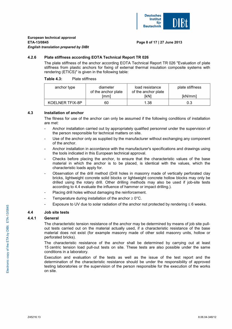
4.2.6 Plate stiffness according EOTA Technical Report TR 026
The plate stiffness of the anchor according EOTA Technical Report TR 026 "Evaluation of plate stiffness from plastic anchors for fixing of external thermal insulation composite systems with rendering (ETICS)" is given in the following table:
Table 4.3: Plate stiffness
anchor type diameter of the anchor plate
[mm]
load resistance of the anchor plate
[kN]
plate stiffness
[kN/mm]
KOELNER TFIX-8P 60 1.38 0.3
4.3 Installation of anchor
The fitness for use of the anchor can only be assumed if the following conditions of installation are met:
- Anchor installation carried out by appropriately qualified personnel under the supervision of the person responsible for technical matters on site.
- Use of the anchor only as supplied by the manufacturer without exchanging any component of the anchor.
- Anchor installation in accordance with the manufacturer's specifications and drawings using the tools indicated in this European technical approval.
- Checks before placing the anchor, to ensure that the characteristic values of the base material in which the anchor is to be placed, is identical with the values, which the characteristic loads apply for.
- Observation of the drill method (Drill holes in masonry made of vertically perforated clay bricks, lightweight concrete solid blocks or lightweight concrete hollow blocks may only be drilled using the rotary drill. Other drilling methods may also be used if job-site tests according to 4.4 evaluate the influence of hammer or impact drilling.).
- Placing drill holes without damaging the reinforcement.
- Temperature during installation of the anchor ≥ 0°C.
- Exposure to UV due to solar radiation of the anchor not protected by rendering ≤ 6 weeks.
4.4 Job site tests
4.4.1 General
The characteristic tension resistance of the anchor may be determined by means of job site pull-out tests carried out on the material actually used, if a characteristic resistance of the base material does not exist (for example masonry made of other solid masonry units, hollow or perforated bricks).
The characteristic resistance of the anchor shall be determined by carrying out at least 15 centric tension load pull-out tests on site. These tests are also possible under the same conditions in a laboratory.
Execution and evaluation of the tests as well as the issue of the test report and the determination of the characteristic resistance should be under the responsibility of approved testing laboratories or the supervision of the person responsible for the execution of the works on site. E
lect
roni
c co
py o
f the
ETA
by
DIB
t: E
TA-1
3/08
45
European technical approval ETA-13/0845 English translation prepared by DIBt
Page 9 of 17 | 27 June 2013
Z45216.13 8.06.04-348/12
Number and position of the anchors to be tested shall be adapted to the relevant special conditions of the site and, for example, to be increased in the case of hidden and larger areas, such that reliable information about the characteristic resistance of the anchor in the base material in question can be derived. The tests shall take into account the most unfavourable conditions of the practical execution.
4.4.2 Assembly
The anchor to be tested shall be installed (e.g. preparation of drill hole, drilling tool to be used, drill bit) and the spacing and the edge distances shall be in the same way as planned for the fixing of the external thermal insulation composite system.
Depending on the drilling tool and according to ISO 5468, hard metal hammer-drill bits or hard metal percussion drill bits, respectively, shall be used. The cutting diameter shall be at the upper tolerance limit.
4.4.3 Execution of test
The test rig used for the pull-out tests shall provide a continuous slow increase of the load, controlled by a calibrated load cell. The load shall apply perpendicular to the surface of the base material and shall be transmitted to the anchor via a hinge. The reaction forces shall be transmitted into the base material at a distance of at least 15 cm from the anchor.
The load shall be increased continuously in a way that the ultimate load is reached after about 1 minute. The load is measured when the ultimate load (N1) is achieved.
4.4.4 Test report
The test report shall include all information necessary to assess the resistance of the tested anchor. It shall be included in the construction dossier.
The minimum data required are:
- Construction site, owner of building; date and location of the tests, air temperature; type of member (ETICS) to be fixed
- Masonry (type of brick, strength class, all dimensions of bricks, mortar group); Visual assessment of masonry (flush joints, joint clearance, regularity)
- Plastic anchor and special-nail; value of the cutting diameter of hard metal hammer-drill bits, measured before and after drilling
- Test rig; results of tests including the indication of value N1
- Tests carried out or supervised by; signature
4.4.5 Evaluation of test results
The characteristic resistance NRk1 is obtained from the measured values of N1 as follows
NRk1 = 0,6 · N1 ≤ 1.5 kN
N1 = the mean value of the five smallest measured values at the ultimate load
Ele
ctro
nic
copy
of t
he E
TA b
y D
IBt:
ETA
-13/
0845
European technical approval ETA-13/0845 English translation prepared by DIBt
Page 10 of 17 | 27 June 2013
Z45216.13 8.06.04-348/12
5 Indications for the manufacturer
5.1 Responsibility of the manufacturer
It is in the responsibility of the manufacturer to ensure that the information on the specific conditions according to 1 and 2 including Annexes referred to 4 is given to those who are concerned. This information may be made by reproduction of the respective parts of the European technical approval. In addition, all installation data shall be shown clearly on the packaging and/or on an enclosed instruction sheet, preferably using illustrations.
The minimum data required are:
- base material for the intended use,
- drill bit diameter,
- maximum thickness of the ETICS,
- minimum anchorage depth,
- minimum hole depth,
- information on the installation procedure,
- identification of the manufacturing batch.
All data shall be presented in a clear and explicit form.
5.2 Packaging, transport and storage
The anchor shall only be supplied as a complete unit.
The anchor shall be stored under normal climatic conditions in its original light-proof packaging. Before installation, it shall not be extremely dried or frozen.
Andreas Kummerow beglaubigt:
p. p. Head of Department Aksünger
Ele
ctro
nic
copy
of t
he E
TA b
y D
IBt:
ETA
-13/
0845
Page 11 of European technical approval ETA-13/0845 of 27 June 2013 English translation prepared by DIBt
Z45187.13 8.06.04-348/12
Insulation support KOELNER TFIX-8P
Product and Intended use
Annex 1
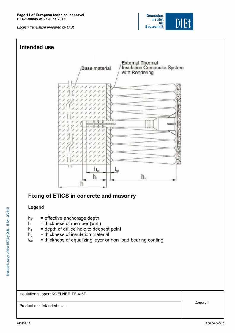
Intended use
Fixing of ETICS in concrete and masonry Legend hef = effective anchorage depth h = thickness of member (wall) h1 = depth of drilled hole to deepest point hd = thickness of insulation material ttol = thickness of equalizing layer or non-load-bearing coating
Ele
ctro
nic
copy
of t
he E
TA b
y D
IBt:
ETA
-13/
0845

Page 12 of European technical approval ETA-13/0845 of 27 June 2013 English translation prepared by DIBt
Z45187.13 8.06.04-348/12
Insulation support KOELNER TFIX-8P
Dimensions
Annex 2
Table 1: Dimensions Anchor sleeve
Base material
ABCD E
Accompanying expansion pin Anchor Type
dnom hef hefE dP
[mm] [mm] [mm] [mm]
TFIX–8P 8 25 65 4.35±0,1
Various lengths of the anchor are permissible: La min = 115mm; La max = 215mm Deteremination of max thickness of insulation: hd = La – ttol – hef z.B. La = 215mm ttol = 10mm hd = 215mm – 10mm – 25mm hd = 180mm
Ele
ctro
nic
copy
of t
he E
TA b
y D
IBt:
ETA
-13/
0845
Page 13 of European technical approval ETA-13/0845 of 27 June 2013 English translation prepared by DIBt
Z45187.13 8.06.04-348/12
Insulation support KOELNER TFIX-8P
Materials Instalation parameters
Annex 3
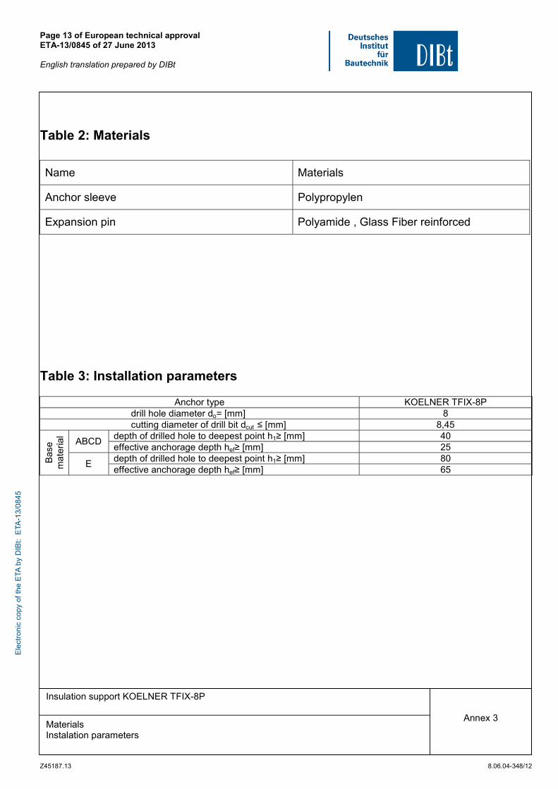
Table 2: Materials Name Materials
Anchor sleeve Polypropylen
Expansion pin Polyamide , Glass Fiber reinforced
Table 3: Installation parameters
Anchor type KOELNER TFIX-8P drill hole diameter do= [mm] 8 cutting diameter of drill bit dcut ≤ [mm] 8,45
depth of drilled hole to deepest point h1≥ [mm] 40 ABCD
effective anchorage depth hef≥ [mm] 25 depth of drilled hole to deepest point h1≥ [mm] 80 B
ase
mat
eria
l
E effective anchorage depth hef≥ [mm] 65
Ele
ctro
nic
copy
of t
he E
TA b
y D
IBt:
ETA
-13/
0845
Page 14 of European technical approval ETA-13/0845 of 27 June 2013 English translation prepared by DIBt
Z45187.13 8.06.04-348/12
Insulation support KOELNER TFIX-8P
Characteristic resistance
Annex 4
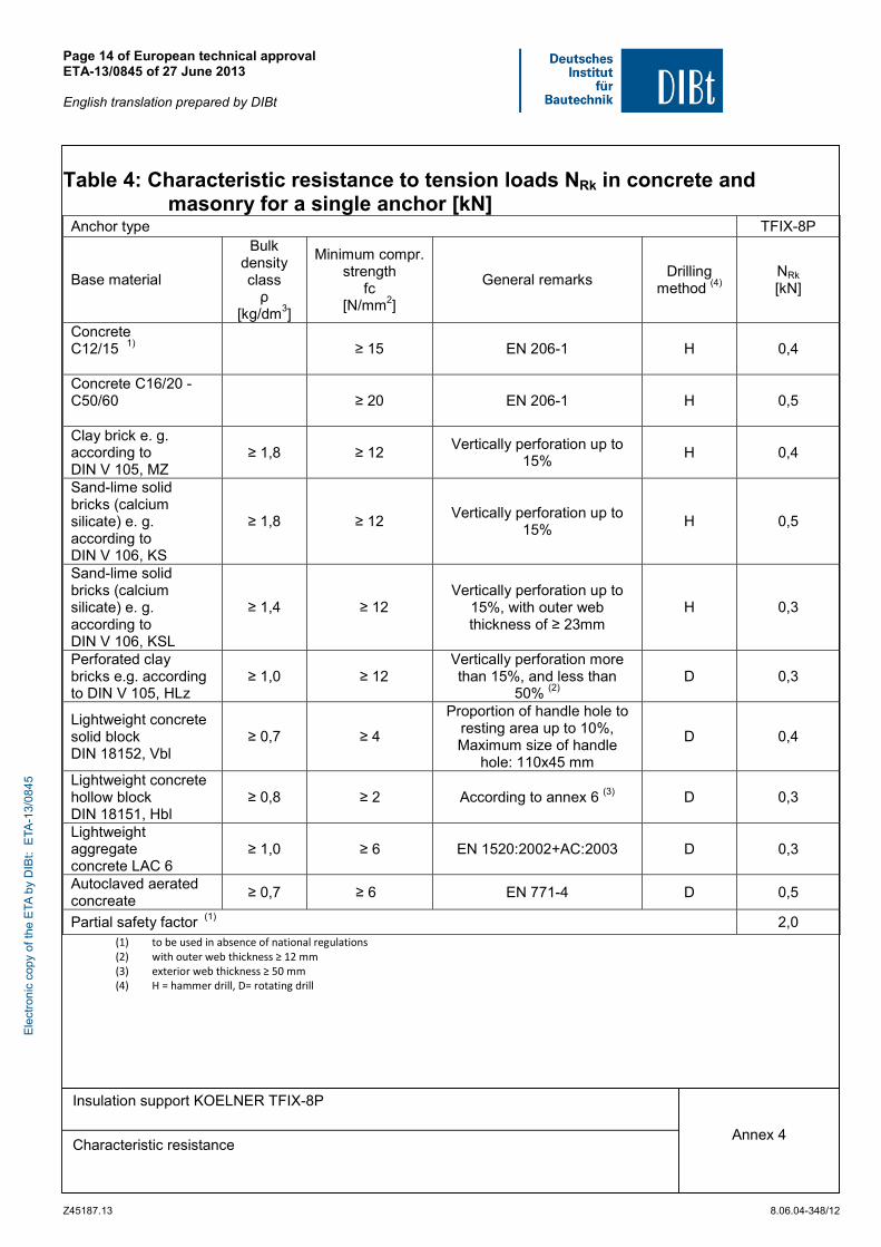
Table 4: Characteristic resistance to tension loads NRk in concrete and
masonry for a single anchor [kN]
(1) to be used in absence of national regulations (2) with outer web thickness ≥ 12 mm (3) exterior web thickness ≥ 50 mm (4) H = hammer drill, D= rotating drill
Anchor type TFIX-8P
Base material
Bulk density class ρ
[kg/dm3]
Minimum compr. strength
fc [N/mm2]
General remarks Drilling
method (4) NRk [kN]
Concrete C12/15 1)
≥ 15 EN 206-1 H 0,4
Concrete C16/20 -C50/60
≥ 20 EN 206-1 H 0,5
Clay brick e. g. according to DIN V 105, MZ
≥ 1,8 ≥ 12 Vertically perforation up to
15% H 0,4
Sand-lime solid bricks (calcium silicate) e. g. according to DIN V 106, KS
≥ 1,8 ≥ 12 Vertically perforation up to
15% H 0,5
Sand-lime solid bricks (calcium silicate) e. g. according to DIN V 106, KSL
≥ 1,4 ≥ 12 Vertically perforation up to
15%, with outer web thickness of ≥ 23mm
H 0,3
Perforated clay bricks e.g. according to DIN V 105, HLz
≥ 1,0 ≥ 12 Vertically perforation more than 15%, and less than
50% (2) D 0,3
Lightweight concrete solid block DIN 18152, Vbl
≥ 0,7 ≥ 4
Proportion of handle hole to resting area up to 10%, Maximum size of handle
hole: 110x45 mm
D 0,4
Lightweight concrete hollow block DIN 18151, Hbl
≥ 0,8 ≥ 2 According to annex 6 (3) D 0,3
Lightweight aggregate concrete LAC 6
≥ 1,0 ≥ 6 EN 1520:2002+AC:2003 D 0,3
Autoclaved aerated concreate
≥ 0,7 ≥ 6 EN 771-4 D 0,5
Partial safety factor (1) 2,0
Ele
ctro
nic
copy
of t
he E
TA b
y D
IBt:
ETA
-13/
0845
Page 15 of European technical approval ETA-13/0845 of 27 June 2013 English translation prepared by DIBt
Z45187.13 8.06.04-348/12
Insulation support KOELNER TFIX-8P
Minimum thickness of members Minimum spacing and edge distances
Annex 5
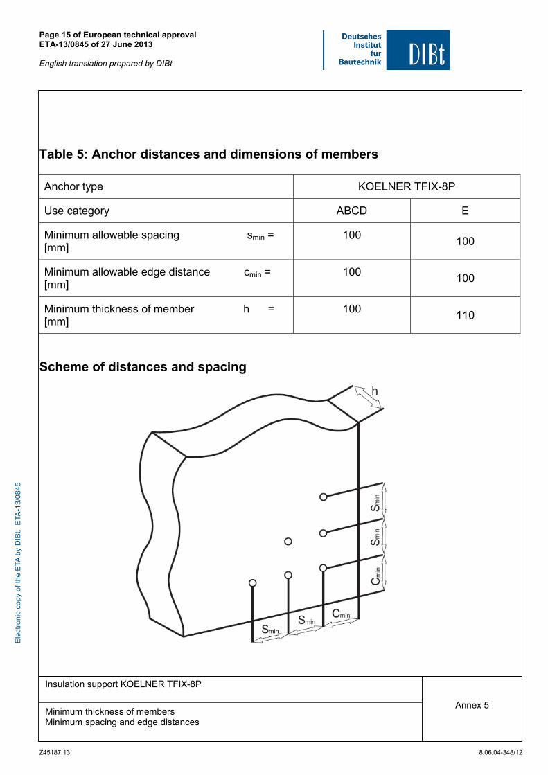
Table 5: Anchor distances and dimensions of members
Anchor type KOELNER TFIX-8P
Use category ABCD E
Minimum allowable spacing smin = [mm]
100 100
Minimum allowable edge distance cmin = [mm]
100 100
Minimum thickness of member h = [mm]
100 110
Scheme of distances and spacing
Ele
ctro
nic
copy
of t
he E
TA b
y D
IBt:
ETA
-13/
0845

Page 16 of European technical approval ETA-13/0845 of 27 June 2013 English translation prepared by DIBt
Z45187.13 8.06.04-348/12
Insulation support KOELNER TFIX-8P
Assingment type of anchor ligchtweight concrete hollow bricks
Annex 6
Table 6: Assignment type of anchor – geometry of bricks for lightweight – concrete blocks according to DIN V 18151-100
Geometry
Thickness of bricks
d
[mm]
Outer web in longitudinal
direction
a
[mm]
Anchor type
TFIX-8P
175 50 ●
240
300 50 ●
The anchor shall be placed in a way that spreading part is anchored in the web of the brick
Ele
ctro
nic
copy
of t
he E
TA b
y D
IBt:
ETA
-13/
0845

Page 17 of European technical approval ETA-13/0845 of 27 June 2013 English translation prepared by DIBt
Z45187.13 8.06.04-348/12
Insulation support KOELNER TFIX-8P
Slip on plates combined with KOELNER TFIX-8P
Annex 7
KWL 140 KWL 110 KWL 090
Table 7: Additional plates, diameter and material
Plate diameter colour Materials
KWL 90 90 nature
KWL 110 110 nature
KWL 140 140 nature
PA6 + GF, PP
Ele
ctro
nic
copy
of t
he E
TA b
y D
IBt:
ETA
-13/
0845