Embed Size (px)
Citation preview
European Space Agency Agence spatiale européenne
ESTEC Keplerlaan 1, PO Box 299, 2200 AG Noordwijk zh,
The Netherlands Tel: +31 71 565 6565 Fax: +31 71 565 5060
European Space Agency Directorate of Technical and Quality Management
STATEMENT OF WORK
Reference: TEC-EEP/2006.92/XX
Issue: 1, Revision 3
Date: 12/04/2007
Appendix 1 to AO/1-5374/07/NL/HE
Statement of Work Issue: 1 Definition and Prototyping of an Autonomous Image Processing Chain Revision: 3 Date: 12/04/2007
European Space Agency Agence spatiale européenne
ESTEC Keplerlaan 1, PO Box 299, 2200 AG Noordwijk zh,
The Netherlands Tel: +31 71 565 6565 Fax: +31 71 565 5060
Page 2 of 33
Table of Content 1 INTRODUCTION......................................................................................................................................... 3
1.1 SCOPE OF THE DOCUMENT ....................................................................................................................... 3 1.2 APPLICABLE AND REFERENCE DOCUMENTS ............................................................................................ 3
1.2.1 Applicable Documents (ADs) .......................................................................................................... 3 1.2.2 Reference Documents (RDs) ........................................................................................................... 3
1.3 ACRONYMS AND ABBREVIATIONS............................................................................................................ 5 2 BACKGROUND AND OBJECTIVE(S) ..................................................................................................... 6
2.1 BACKGROUND.......................................................................................................................................... 6 2.2 OBJECTIVE(S) OF THE ACTIVITY .............................................................................................................. 6 2.3 IMAGE PROCESSING CHAIN DESCRIPTION................................................................................................ 7 2.4 RELATED ACTIVITIES............................................................................................................................. 10 2.5 ESA RELATED ACTIVITIES .................................................................................................................... 11
3 WORK TO BE PERFORMED.................................................................................................................. 11 3.1 WORK LOGIC ......................................................................................................................................... 11 3.2 TASK DESCRIPTION................................................................................................................................ 12
3.2.1 Task 1: State-of-the-Art Review, Requirements Baseline and Technical Specification................. 12 3.2.2 Task 2: Detailed Design & Implementation.................................................................................. 13 3.2.3 Task 3: Software Verification & Validation.................................................................................. 13 3.2.4 Task 4: End-to-end performance test case .................................................................................... 13 3.2.5 Task 5: Synthesis, recommendations and future work .................................................................. 14
4 REQUIREMENTS FOR MANAGEMENT, REPORTING, MEETINGS AND DELIVERABLES .. 15 4.1 MANAGEMENT....................................................................................................................................... 15 4.2 REPORTING ............................................................................................................................................ 15 4.3 MEETINGS.............................................................................................................................................. 15 4.4 DELIVERABLES ...................................................................................................................................... 15
4.4.1 Documentation & Data ................................................................................................................. 16 4.4.2 Software ........................................................................................................................................ 17
5. SCHEDULE AND MILESTONES............................................................................................................ 17
ANNEX 0: DEFINITIONS................................................................................................................................. 19
ANNEX 1: ECSS-E40 TAILORING................................................................................................................. 20 Introduction................................................................................................................................................... 20 Description of the tailoring........................................................................................................................... 20 List of ECSS-E40 applicable requirements ................................................................................................... 24 Document Requirement List [as specified in ECSS-E-40 part 2B (15 November 2004)] ............................. 29
ANNEX 2: SOFTWARE REQUIREMENTS................................................................................................... 32
Statement of Work Issue: 1 Definition and Prototyping of an Autonomous Image Processing Chain Revision: 3 Date: 12/04/2007
European Space Agency Agence spatiale européenne
ESTEC Keplerlaan 1, PO Box 299, 2200 AG Noordwijk zh,
The Netherlands Tel: +31 71 565 6565 Fax: +31 71 565 5060
Page 3 of 33
1 Introduction
1.1 Scope of the Document
This document describes the activity to be executed and the deliverables required by the European Space Agency in relation to the study “Definition and Prototyping of an Autonomous Image Processing Chain”.
This document will be part of the contract and shall serve as an applicable document throughout the execution of the work.
The objective of this activity of the GSP (General Studies Programme) is to define a generic architecture for an autonomous optical imagery processing chain and to implement it as a prototype version for a high spatial resolution Earth Observation sensor with rectangular geometry (e.g. push-broom or whisk-broom).
The outcome of this study might be re-used for future missions such as Sentinel-2 [RD-20] or Sentinel-3 [RD-21]. 1.2 Applicable and Reference Documents
The documents listed in the following sections shall be considered as applicable and reference.
1.2.1 Applicable Documents (ADs)
The following documents, listed in order of precedence, contain requirements applicable to the activity: AD-1 ECSS-E-40 Part 1B; Space Engineering – Software; 28 November 2003
http://www.ecss.nl/ 1.2.2 Reference Documents (RDs)
The following documents can be consulted by the Contractor as they contain relevant information:
RD-1 Schowengerdt, R. A. (1997). Remote Sensing Models and Methods for Image Processing, ISBN: 0126289816, Editorial Elsevier, pp. 522.
RD-2 GMES (Global Monitoring for Environment and Security) website: http://www.gmes.info
Statement of Work Issue: 1 Definition and Prototyping of an Autonomous Image Processing Chain Revision: 3 Date: 12/04/2007
European Space Agency Agence spatiale européenne
ESTEC Keplerlaan 1, PO Box 299, 2200 AG Noordwijk zh,
The Netherlands Tel: +31 71 565 6565 Fax: +31 71 565 5060
Page 4 of 33
RD-3 Baillarin, S., Bouillon, A., Bernard, M., Chikhi, M. (2005), Using a Three Dimensional Spatial Database to Orthorectify Automatically Remote Sensing Images. ISPRS Workshop on Service and Application of Spatial Data Infrastructure, XXXVI (4/W6), Oct.14-16, Hangzhou, China.
RD-4 PCI Geomatics Web Page: http://www.pcigeomatics.com
RD-5 Philippe Goudy, Philippe Kubik, Bernard Rouge, Christophe Latry (2002). From Image Processing Concepts to Instrument Design in Remote Sensing Satellites. Proceedings EUSIPCO 2002. Volume II pp 431-434.
RD-6 ENVI Web Page: http://www.ittvis.com/envi/
RD-7 Schiller, C.; Triebnig, G.; Kim, Y.; Maass, H. (2005). KOMPSAT European cooperation. Geoscience and Remote Sensing Symposium, 2005. IGARSS '05. Proceedings. 2005 IEEE International. Volume 2, 25-29 July 2005 Page(s):1173 - 1176
RD-8 Jinsong Chen, Hui Lin, Yun Shao, Limin Yang (2006). Oblique striping removal in remote sensing imagery based on wavelet transform. International Journal of Remote Sensing. Volume 27, Number 8 / 20, pp. 1717 – 1723.
RD-9 Yong Du Cihlar, J. Beaubien, J. Latifovic, R. (2001). Radiometric normalization, compositing, and quality control forsatellite high resolution image mosaics over large areas. Geoscience and Remote Sensing, IEEE Transactions on; Volume: 39, Issue: 3; pp. 623-634.
RD-10 Jalobeanu, A. Blanc-Feraud, L. Zerubia, J. (2000) Satellite image deconvolution using complex wavelet packets. Image Processing, 2000. Proceedings. 2000 International Conference on; Vol.3, pp. 809-812 vol.3.
RD-11 A. Jalobeanu1, L. Blanc-Féraud, J. Zerubia (2006). Adaptive Parameter Estimation for Satellite Image Deconvolution. INRIA research report. Internal reference: RR-3956.
RD-12 Web link: http://eu.spaceref.com/news/viewpr.html?pid=12727
RD-13 Statement of Work document of the ESA Contract 20226/06/NL/HE "A Physical Model for Analysing the Geometric Errors of Remote Sensing Imagery".
RD-14 Yong Du Cihlar, J. Beaubien, J. Latifovic, R. (2001). Radiometric normalization, compositing, and quality control forsatellite high resolution image mosaics over large areas. Geoscience and Remote Sensing, IEEE Transactions on; Vol. 39, Issue 3; pp. 623-634.
RD-15 VICAR webpage: http://www-mipl.jpl.nasa.gov/external/vicar.html
RD-16 MIPL webpage: http://www-mipl.jpl.nasa.gov/
RD-17 ISIS webpage: http://isis.astrogeology.usgs.gov/
RD-18 European Planetary Mapping GREEN PAPER, Europlanet Conference 2006.
Statement of Work Issue: 1 Definition and Prototyping of an Autonomous Image Processing Chain Revision: 3 Date: 12/04/2007
European Space Agency Agence spatiale européenne
ESTEC Keplerlaan 1, PO Box 299, 2200 AG Noordwijk zh,
The Netherlands Tel: +31 71 565 6565 Fax: +31 71 565 5060
Page 5 of 33
RD-19 ALOS (Advanced Land Observing Satellite) webpage: http://www.jaxa.jp/projects/sat/alos/index_e.html
RD-20 ESA Open Invitation To Tender Documentation for “GMES SENTINEL-2 PHASE B2/C/D/E1”. AO5340. 16/02/2007.
RD-21 ESA Open Invitation To Tender Documentation for “GMES SENTINEL-3 PHASE B2/C/D/E1”. AO5314. 12/02/2007.
RD-22 Dial G., Grodecki J. (2002). IKONOS Accuracy without Ground Control. Proceedings of the Integrated Remote Sensing at the Global, Regional and Local Scale ISPRS Symposium. 10-15 November 2002, Denver, CO USA.
RD-23 AMORGOS Automated MERIS ORtho-rectified Geo-location Operational Software). http://earth.esrin.esa.it/resources/softwaretools/
RD-24 VEGETATION Web Page: http://vegetation.cnes.fr/ RD-25 PLEIADES Web Page: http://smsc.cnes.fr/PLEIADES/RD-26 MERIS Web Page: http://envisat.esa.int/object/index.cfm?fobjectid=1665RD-27 FORMOSAT-2: http://www.spotimage.fr/html/_167_171_977_979_.phpRD-28 KOMPSAT-2: http://www.spotimage.fr/html/_167_171_1155_.phpRD-29 Dial, G., Grodecki, J. (2002). Block Adjustment with Rational Polynomial
Camera Models. ACSM-ASPRS 2002 Annual Conference Proceedings. RD-30 MERIS Handbook: http://envisat.esa.int/dataproducts/meris/toc.htm
1.3 Acronyms and abbreviations
ANDORRE Atelier Numérique D’ORthoREctification AR Acceptance Review ARCS Austrian Research Centers CNES Centre National d’Études Spatiales DLR Deutsches Zentrum für Luft- und Raumfahrt ESA European Space Agency FR Final Review GCP Ground Control Point GMES Global Monitoring for Environment and Security IGN Institut Géographique National KARI Korea Aerospace Research Institute MTF Modulation Transfer Function NLR Nationaal Lucht- en Ruimtevaartlaboratorium PDR Preliminary Design Review PSF Point Spread Function QR Qualification Review RPC Rational Polynomial Coefficient SPOT Satellite Pour l’Observation de la Terre TP Tie Point VHR Very High Resolution
Statement of Work Issue: 1 Definition and Prototyping of an Autonomous Image Processing Chain Revision: 3 Date: 12/04/2007
European Space Agency Agence spatiale européenne
ESTEC Keplerlaan 1, PO Box 299, 2200 AG Noordwijk zh,
The Netherlands Tel: +31 71 565 6565 Fax: +31 71 565 5060
Page 6 of 33
2 Background and Objective(s)
2.1 Background With the advent of the GMES (Global Monitoring for Environment and Security) [RD-2] satellite missions, the automatic processing of high resolution imagery will be a central issue. The main purpose of GMES is to provide a continuous global monitoring and, as a consequence, a huge amount of data will be produced at high-resolution (metric to decametric) which will require accurate and automated image quality processing, ortho-rectification and mosaicking. This is considered a critical issue within the frame of the GMES programme. The success of the GMES programme and, in general, development of the remote sensing market is highly dependant on the real-time processing of the data and as a consequence require a minimisation of the human intervention in the generation of ortho-rectified and mosaicked imagery with the highest radiometric quality. In Planetary Science, a large number of missions (e.g. VEX, MEX, SMART-1, Rosetta, and BepiColombo) are and will be acquiring an enormous amount of optical imagery. Therefore image processing tools for this data are a real present and future need. Although this study is mainly focused for Earth Observation, its outcome could also be beneficial for Space Science missions.
2.2 Objective(s) of the Activity The objective of this activity is to define and implement an autonomous and fast image processing chain for optical remote sensing missions at high spatial resolution and with a rectangular geometry (push-broom or whisk-broom). This chain shall include the following functions (see definitions in the following section):
A. Calibration B. Equalization C. De-convolution. D. De-noising. E. Co-registration. F. Ortho-rectification. G. Mosaicking.
Ortho-rectification will only be considered and implemented under a relatively simplified and straight-forward method as it is covered in higher detail in the frame of another study [RD-13]. It is also important to point out that all the functions mentioned here before are not necessarily sequential (e.g. de-convolution and de-noising can be combined). This software shall be tested for a representative geographical area (including both high and low topography variations) using synthetic and real imagery. The processing chain shall be delivered as operational software.
Statement of Work Issue: 1 Definition and Prototyping of an Autonomous Image Processing Chain Revision: 3 Date: 12/04/2007
European Space Agency Agence spatiale européenne
ESTEC Keplerlaan 1, PO Box 299, 2200 AG Noordwijk zh,
The Netherlands Tel: +31 71 565 6565 Fax: +31 71 565 5060
Page 7 of 33
2.3 Image Processing Chain Description
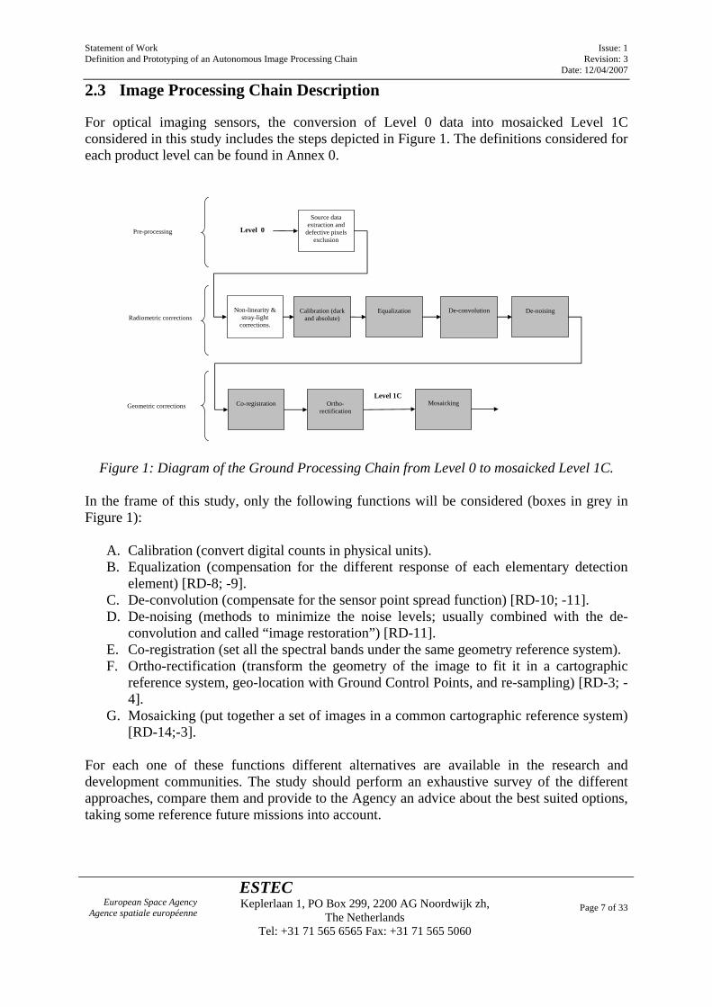
For optical imaging sensors, the conversion of Level 0 data into mosaicked Level 1C considered in this study includes the steps depicted in Figure 1. The definitions considered for each product level can be found in Annex 0.
Source data extraction and
defective pixels exclusion
Level 0
Non-linearity &
stray-light corrections.
Equalization
De-convolution
De-noising
Co-registration
Mosaicking
Level 1C
Pre-processing
Radiometric corrections
Geometric corrections
Ortho-rectification
Calibration (dark
and absolute)
Figure 1: Diagram of the Ground Processing Chain from Level 0 to mosaicked Level 1C.
In the frame of this study, only the following functions will be considered (boxes in grey in Figure 1):
A. Calibration (convert digital counts in physical units). B. Equalization (compensation for the different response of each elementary detection
element) [RD-8; -9]. C. De-convolution (compensate for the sensor point spread function) [RD-10; -11]. D. De-noising (methods to minimize the noise levels; usually combined with the de-
convolution and called “image restoration”) [RD-11]. E. Co-registration (set all the spectral bands under the same geometry reference system). F. Ortho-rectification (transform the geometry of the image to fit it in a cartographic
reference system, geo-location with Ground Control Points, and re-sampling) [RD-3; -4].
G. Mosaicking (put together a set of images in a common cartographic reference system) [RD-14;-3].
For each one of these functions different alternatives are available in the research and development communities. The study should perform an exhaustive survey of the different approaches, compare them and provide to the Agency an advice about the best suited options, taking some reference future missions into account.
Statement of Work Issue: 1 Definition and Prototyping of an Autonomous Image Processing Chain Revision: 3 Date: 12/04/2007
European Space Agency Agence spatiale européenne
ESTEC Keplerlaan 1, PO Box 299, 2200 AG Noordwijk zh,
The Netherlands Tel: +31 71 565 6565 Fax: +31 71 565 5060
Page 8 of 33
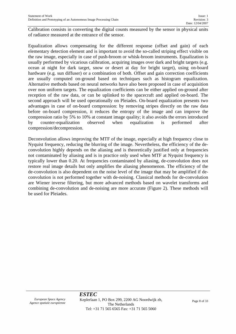
Calibration consists in converting the digital counts measured by the sensor in physical units of radiance measured at the entrance of the sensor. Equalization allows compensating for the different response (offset and gain) of each elementary detection element and is important to avoid the so-called striping effect visible on the raw image, especially in case of push-broom or whisk-broom instruments. Equalization is usually performed by vicarious calibration, acquiring images over dark and bright targets (e.g. ocean at night for dark target, snow or desert at day for bright target), using on-board hardware (e.g. sun diffuser) or a combination of both. Offset and gain correction coefficients are usually computed on-ground based on techniques such as histogram equalization. Alternative methods based on neural networks have also been proposed in case of acquisition over non uniform targets. The equalization coefficients can be either applied on-ground after reception of the raw data, or can be uplinked to the spacecraft and applied on-board. The second approach will be used operationally on Pleiades. On-board equalization presents two advantages in case of on-board compression: by removing stripes directly on the raw data before on-board compression, it reduces the entropy of the image and can improve the compression ratio by 5% to 10% at constant image quality; it also avoids the errors introduced by counter-equalization observed when equalization is performed after compression/decompression. Deconvolution allows improving the MTF of the image, especially at high frequency close to Nyquist frequency, reducing the blurring of the image. Nevertheless, the efficiency of the de-convolution highly depends on the aliasing and is theoretically justified only at frequencies not contaminated by aliasing and is in practice only used when MTF at Nyquist frequency is typically lower than 0.20. At frequencies contaminated by aliasing, de-convolution does not restore real image details but only amplifies the aliasing phenomenon. The efficiency of the de-convolution is also dependent on the noise level of the image that may be amplified if de-convolution is not performed together with de-noising. Classical methods for de-convolution are Wiener inverse filtering, but more advanced methods based on wavelet transforms and combining de-convolution and de-noising are more accurate (Figure 2). These methods will be used for Pleiades.
Statement of Work Issue: 1 Definition and Prototyping of an Autonomous Image Processing Chain Revision: 3 Date: 12/04/2007
European Space Agency Agence spatiale européenne
ESTEC Keplerlaan 1, PO Box 299, 2200 AG Noordwijk zh,
The Netherlands Tel: +31 71 565 6565 Fax: +31 71 565 5060
Page 9 of 33
Figure 2: SPOT-3 image from Cayenne. Up: blurred and noisy; Bottom: De-convolved with algorithm from INRIA (France) [RD-11]. Co-registration consists in setting all the spectral bands under the same geometry reference system. This function is based on image correlation following adequate pre-processing (e.g. over-sampling, epipolar geometry rotation and radiometry dynamics adaptation). Image correlation is the critical step of the co-registration of the different spectral bands. Classical methods for image correlation rely on moving a reference window into a search window, computing the correlation coefficient at each location, build a 2D correlation surface and search for the maximum of the correlation surface by interpolation method. Alternative techniques based on dichotomic re-sampling of the reference and search windows and computation of the correlation surface at increasing spatial resolution have also been developed and proved to be more accurate, with typical correlation accuracy below 0.1 pixel, vs 0.2 to 0.3 pixels for classical methods. This dichotomic-resampling based image correlation technique has been used for VEGETATION [RD-24] and will also be used on VHR (Very High Resolution) sensors such as Pleiades [RD-25]. Image ortho-rectification is implemented in the frame of this study by an automated procedure making use of GCPs (Ground Control Points) and/or TPs (Tie Points). The contractor can also make use of Rational Polynomial Coefficient (RPC) functions to establish the ground-to-image relationship for a given sensor [RD-22; -29]. For the ortho-rectification, image correlation is also a critical step because it drives the accuracy of the Ground Control Points/Tie Points (GCP/TP) extraction, which has a direct impact on the overall geo-location performance.
Image mosaicking is important to satisfy the needs of users who are interested in a geographical area larger than a single image. The main problems to be solved are the
Statement of Work Issue: 1 Definition and Prototyping of an Autonomous Image Processing Chain Revision: 3 Date: 12/04/2007
European Space Agency Agence spatiale européenne
ESTEC Keplerlaan 1, PO Box 299, 2200 AG Noordwijk zh,
The Netherlands Tel: +31 71 565 6565 Fax: +31 71 565 5060
Page 10 of 33
difference in observation conditions that induce difference of spatial resolution between the images to be mosaicked, difference of sun illumination, and problems of hidden areas in case of high topography variation areas such as major cities or steep slope mountains and cliffs. If there is a time delay between the two image acquisitions, then ground targets or clouds may have moved in between, leading to a more complex mosaicking task. In order to get a seamless automatic mosaicking, an automatic selection of the cutline between two neighbouring images is definitely needed: classically lineal features such as roads, small rivers are used and need then to be automatically detected and matched between the two images. This usually relies then on image texture analysis (e.g. using gradient images and looking for lineal structures) and perform a correlation between the two images to locate the position of the cutline in the two images. This has been investigated in the frame of VHR missions such as Pleiades [RD-12].
2.4 Related Activities
For Earth Observation, the functions planned for this automated image processing chain have already been developed in different frameworks.
Functions A, B, C and D (Calibration, Equalisation over uniform scenes, De-convolution and De-noising) have been deeply studied in Europe by CNES (Centre National d’Études Spatiales) in the frame of the SPOT and Pleiades programmes [RD-5].
Functions E, F and G (Co-registration, ortho-rectification and mosaicking) have been more widely investigated and implemented for operational services. Thus, for instance, CNES together with IGN (Institut Géographique National) and SPOT Image have recently collaborated in the development of a processing chain for the automatic ortho-rectification of SPOT imagery (named ANDORRE [RD-3]). Another important initiative is the joint effort between ARCS (Austrian Research Centers), DLR (Deutsches Zentrum für Luft- und Raumfahrt), NLR (Nationaal lucht- en ruimtevaartlaboratorium) and KARI (Korea Aerospace Research Institute) to automate the processing of Kompsat data [RD-7; -28].
Also private initiatives have implemented chains for automatically perform functions E and F. One of the world leading software is PCI Geomatics [RD-4] with its Image Correction System (ICS) which automates the processing and preparation of remote sensing imagery and allows to achieve instantly time/cost savings for ortho-rectification. Other image processing software like ENVI [RD-6] also implement basic functions for automatically ortho-rectify for instance Ikonos data.
In Space Science, image processing is mainly relying on American software, one called VICAR [RD-15] developed by the Multimission Image Processing Laboratory (MIPL) [RD-16] at NASA, and the other one called ISIS developed by the USGS [RD-17]. VICAR is currently being used for processing HRSC on Mars Express and VMC on Venus Express. These two software packages are already implementing in a certain way functions E and F.
It is also important to mention that at the last Europlanet conference, there was a workshop especially devoted to planetary mapping. The purpose was to coordinate the current activities around an European planetary mapping program. This is the same type of role performed by the USGS in the USA. During this conference, it was drafted a green paper [RD-18].
Statement of Work Issue: 1 Definition and Prototyping of an Autonomous Image Processing Chain Revision: 3 Date: 12/04/2007
European Space Agency Agence spatiale européenne
ESTEC Keplerlaan 1, PO Box 299, 2200 AG Noordwijk zh,
The Netherlands Tel: +31 71 565 6565 Fax: +31 71 565 5060
Page 11 of 33
2.5 ESA Related Activities
Concerning the ground processing chain of medium-resolution optical imaging instruments, main ESA experience is around the processing chain for MERIS on Envisat [RD-26; -30]. In this frame, for instance, one of the tools developed by ESA is AMORGOS (Accurate MERIS Ortho-Rectified Geo-location Operational Software) which performs accurate geo-location [RD-23]. Concerning the automatic ortho-rectification, another ESA activity is being carried out in the frame of a GSP study named "A Physical Model for Analysing the Geometric Errors of Remote Sensing Imagery" [RD-13]. This activity aims at developing an automated ortho-rectification processor for optical imagery using a physically-based line-of-sight (LOS) model. As mentioned before, due to the fact that this function is already covered by other on-going activities, a complex and automated ortho-rectification function will not be considered in this study and this function will only be implemented in the processor using a relatively simple approach based on GCPs/TPs and possibly Rational Polynomial Coefficient (RPC) in order to establish the link between the image pixels and their ground location [RD-22].
3 Work to be Performed
3.1 Work Logic
This study is composed of three parts. First part (including Task 1) will conclude with a first milestone at the PDR (Preliminary Design Review). Second part (including Tasks 2 and 3) will conclude at the QR+AR (Qualification and Acceptance Review). Third part (including Tasks 4 and 5) will conclude at the FR (Final Review). This study shall comply with the tailored version of ECSS-E40 [AD-1] which is included in Annex 1 and with the Software Requirements from Annex 2. The first task (“State-of-the-art Review, Requirements Baseline and Technical Specification”) will conclude with the PDR where the RB (Requirements Baseline) and TS (Technical Specification) data packages will be evaluated and subject to ESA approval. A draft version of RB shall be delivered 2 months before PDR. At PDR also a first version of the “Software Validation Testing Specification wrt RB” and a “Test Case Plan” (not specified in ECSS-E40) will be delivered to the Agency for approval. After PDR being declared successful, Task 2 (“Detailed Design & Implementation”) will start the design and implementation of the tool. A draft version of the DDF (Design Definition File) data package will be delivered to the Agency in the middle of Task 2. At the end of Task 2, the final version of the DDF data package will be delivered to the Agency for approval. Task 3 (“Software Verification & Validation”) will start sometime during Task 2 and run for a certain period in parallel. DJF (Design Justification File) data package will be delivered to the
Statement of Work Issue: 1 Definition and Prototyping of an Autonomous Image Processing Chain Revision: 3 Date: 12/04/2007
European Space Agency Agence spatiale européenne
ESTEC Keplerlaan 1, PO Box 299, 2200 AG Noordwijk zh,
The Netherlands Tel: +31 71 565 6565 Fax: +31 71 565 5060
Page 12 of 33
Agency at the end of Task 3 (QR+AR meeting) and a draft version will be delivered at least one month before the end of Task 3. Task 4 (“End-to-end performance test case”) and Task 5 (“Synthesis, recommendations and future work”) will conclude with a Final Review (FR) where all the deliverables will be submitted to the Agency for approval. The modification and problem analysis report (Maintenance File data package) will be delivered at the Final Review and at the end of the contract. 3.2 Task Description
3.2.1 Task 1: State-of-the-Art Review, Requirements Baseline and Technical Specification
Input
The interfacing of the ortho-rectification functional module will be specified by the Agency.
Task description
For the functions of an image processing chain considered in this study (Calibration, equalization, de-convolution, de-noising, co-registration, ortho-rectification and mosaicking) as described in Chapter 2.3, make an exhaustive review of the approaches used by the community (scientific and industrial).
Select an approach for each function of the processing chain through a trade-off process and justify the choices made considering the performance in terms of image quality (geometric and radiometric) and processing time.
Generate the RB (Requirements Baseline) and TS (Technical Specification) for the software according to the requirements listed in Annex 2 and following the tailored ECSS-E40 specified in Annex 1.
This task will also include the definition of the “Software Validation Testing Specification wrt RB” and a “Test Case Plan” (not specified in ECSS-E40). These documents shall detail the validation strategy and all the inputs required.
Output / Approval conditions
• Report describing the findings and justifying the choices made.
• RB and TS data packages.
• “Software Validation Testing Specification wrt RB”
• “Test Case Plan” (for Task 4).
Statement of Work Issue: 1 Definition and Prototyping of an Autonomous Image Processing Chain Revision: 3 Date: 12/04/2007
European Space Agency Agence spatiale européenne
ESTEC Keplerlaan 1, PO Box 299, 2200 AG Noordwijk zh,
The Netherlands Tel: +31 71 565 6565 Fax: +31 71 565 5060
Page 13 of 33
Data package related to Task 1 shall be submitted to ESA approval and shall be reported at PDR.
3.2.2 Task 2: Detailed Design & Implementation
Input
Outputs from Task 1.
Task description
Based on the RB and the TS, design and implement the processing chain in compliance with the requirements listed in Annex 2 and the ECSS-E40 tailoring (Annex 1).
Output / Approval conditions
Delivery of DDF (Design Definition File) and DJF (Design Justification File) data packages.
3.2.3 Task 3: Software Verification & Validation
Input
Dataset required for performing the verification and validation of the software as specified in the “Software Validation Testing Specification wrt RB”. Required data shall be provided by the Contractor and will be delivered to the Agency at the end of the Task.
Additional datasets and associated test cases might be proposed by the Agency.
Task description The goal of this Task is to perform a functional verification and validation of the processing chain following the specifications included in the “Software Validation Testing Specification wrt RB”.
Output / Approval conditions
Delivery of MF (Maintenance File), MGT (Management File) and updated DDF and DJF.
Data package related to Task 2 and 3 shall be submitted to ESA approval and shall be reported at QR+AR.
3.2.4 Task 4: End-to-end performance test case
Input
Output of Tasks 2 and 3.
Statement of Work Issue: 1 Definition and Prototyping of an Autonomous Image Processing Chain Revision: 3 Date: 12/04/2007
European Space Agency Agence spatiale européenne
ESTEC Keplerlaan 1, PO Box 299, 2200 AG Noordwijk zh,
The Netherlands Tel: +31 71 565 6565 Fax: +31 71 565 5060
Page 14 of 33
Dataset required for performing the verification and validation of the software as specified in the “Test Case Plan”. The required data shall be provided by the Contractor and will be delivered to the Agency at the end of the Task.
Task description
The objective of this Task is to validate the performance of the image processing chain according to the procedure and performance goals specified in the “Test Case Plan”.
The validation shall use as input of the chain real space-borne or air-borne imagery (potentially pre-processed, for instance, to simulate a lower resolution sensor simulating a precise PSF, Point Spread Function, or noise level). Different tests, for different functional modules can be performed with different images (from space-borne or air-borne sensors). This software shall be tested for a representative geographical area (including both high and low topography variations).
Possible auxiliary data might include:
• Sensor and platform characteristics (e.g. PSF (Point Spread Function), noise levels, etc.).
• GCPs, TPs and RPC (Rational Polynomial Coefficient) functions for performing the ortho-rectification.
• DEM (Digital Elevation Model) for the selected test site.
• Ground truth for validating the geometric and radiometric corrections (GCPs, TPs, radiometric reference measurements, etc.).
Output / Approval conditions
Report describing the results and recommendations obtained from this test case subject to ESA approval.
3.2.5 Task 5: Synthesis, recommendations and future work
Input
Output from all previous Tasks.
Task description
Synthesis and report of all the findings obtained from this study, giving some recommendations to the Agency and pointing in which direction future work should go (including maintenance).
The recommendations and future work shall include considerations about the future adaptation of the processing chain for coarser resolution sensors (e.g. Sentinel-3 optical imaging sensors).
Statement of Work Issue: 1 Definition and Prototyping of an Autonomous Image Processing Chain Revision: 3 Date: 12/04/2007
European Space Agency Agence spatiale européenne
ESTEC Keplerlaan 1, PO Box 299, 2200 AG Noordwijk zh,
The Netherlands Tel: +31 71 565 6565 Fax: +31 71 565 5060
Page 15 of 33
Output / Approval conditions
Chapter of the Final Report containing the synthesis of the study, the recommendations to the Agency and the work that should be carried out in the future. Elaborate conclusions, recommendations for the Agency and describe future work that should be undertaken.
4 Requirements for Management, Reporting, Meetings and Deliverables
The standard requirements for Management, Reporting, Meetings and Deliverables (Appendix 2 to the Contract) shall apply, taking account of the following specific requirements for the present activity, which shall prevail in case of conflict.
4.1 Management
Section 1 of the Standard Requirements for Management, Reporting, Meetings and Deliverables shall apply. 4.2 Reporting
Section 2 of the Standard Requirements for Management, Reporting, Meetings and Deliverables shall apply.
4.3 Meetings
Section 3 of the Standard Requirements for Management, Reporting, Meetings and Deliverables shall apply.
4.4 Deliverables
The Contractor shall deliver the following items according to the definitions specified in the Standard Requirements for Management, Reporting, Meetings and Deliverables (Appendix 2 of the Contract) and ECSS-E-40 [AD-1]:
• RB and TS data package
• Report Task 1.
• “Software Validation Testing Specification wrt RB” from DJF data package.
• “Test Case Plan” (for Task 4).
• DDF data package
• DJF data package
• MF data package
Statement of Work Issue: 1 Definition and Prototyping of an Autonomous Image Processing Chain Revision: 3 Date: 12/04/2007
European Space Agency Agence spatiale européenne
ESTEC Keplerlaan 1, PO Box 299, 2200 AG Noordwijk zh,
The Netherlands Tel: +31 71 565 6565 Fax: +31 71 565 5060
Page 16 of 33
• MGT data package
• Report Task 4.
• Final Report
• Executive Summary
• Abstract
• Computer programs and models
The contractor shall set up a FTP site where all deliverables of this activity shall be uploaded and continuously updated along the duration of the contract. In addition, the electronic presentation material from progress meetings shall also be stored on this FTP site.
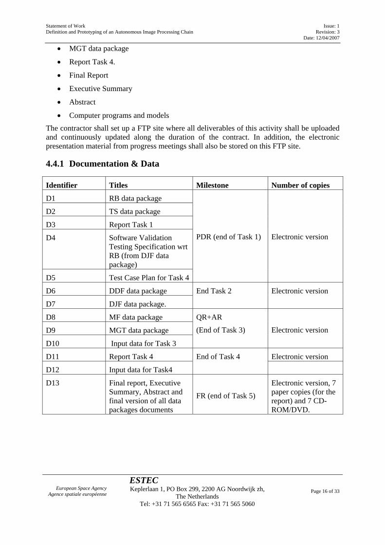
4.4.1 Documentation & Data
Identifier Titles Milestone Number of copies
D1 RB data package
D2 TS data package
D3 Report Task 1
D4 Software Validation Testing Specification wrt RB (from DJF data package)
D5 Test Case Plan for Task 4
PDR (end of Task 1)
Electronic version
D6 DDF data package
D7 DJF data package.
End Task 2 Electronic version
D8 MF data package
D9 MGT data package
D10 Input data for Task 3
QR+AR
(End of Task 3)
Electronic version
D11 Report Task 4 Electronic version
D12 Input data for Task4
End of Task 4
D13 Final report, Executive Summary, Abstract and final version of all data packages documents
FR (end of Task 5)
Electronic version, 7 paper copies (for the report) and 7 CD-ROM/DVD.
Statement of Work Issue: 1 Definition and Prototyping of an Autonomous Image Processing Chain Revision: 3 Date: 12/04/2007
European Space Agency Agence spatiale européenne
ESTEC Keplerlaan 1, PO Box 299, 2200 AG Noordwijk zh,
The Netherlands Tel: +31 71 565 6565 Fax: +31 71 565 5060
Page 17 of 33
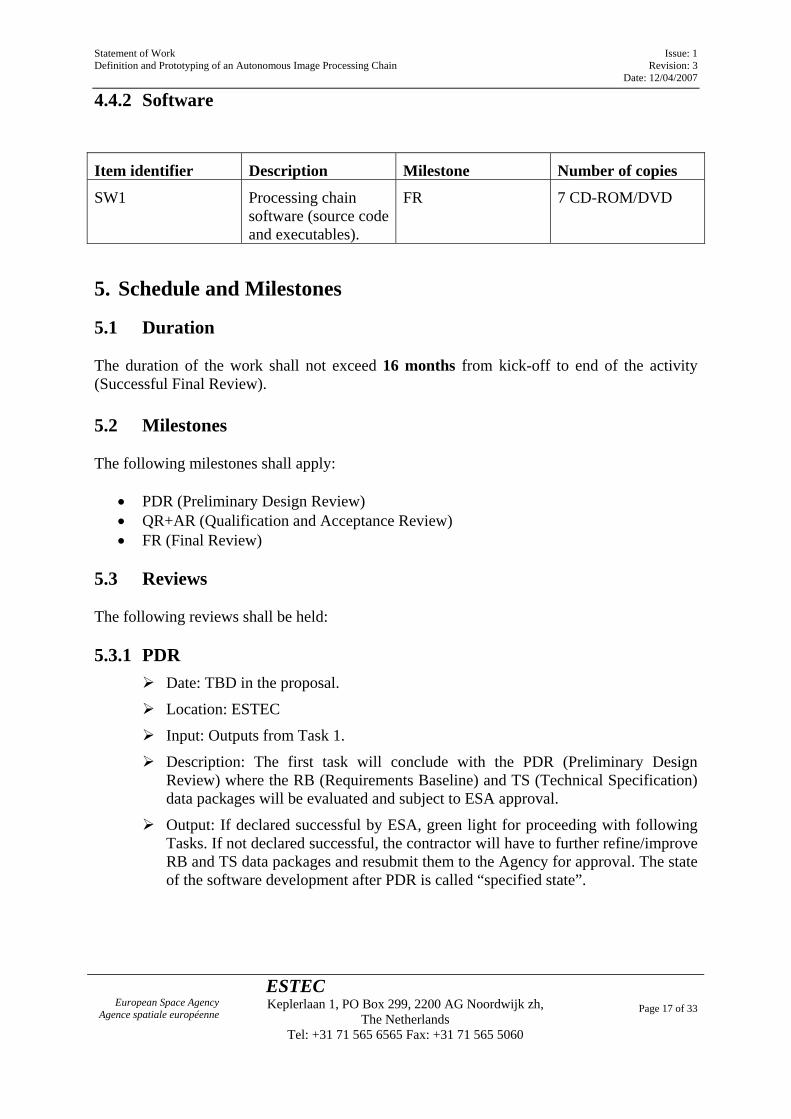
4.4.2 Software
Item identifier Description Milestone Number of copies
SW1 Processing chain software (source code and executables).
FR 7 CD-ROM/DVD
5. Schedule and Milestones
5.1 Duration The duration of the work shall not exceed 16 months from kick-off to end of the activity (Successful Final Review). 5.2 Milestones The following milestones shall apply:
• PDR (Preliminary Design Review) • QR+AR (Qualification and Acceptance Review) • FR (Final Review)
5.3 Reviews The following reviews shall be held: 5.3.1 PDR
Date: TBD in the proposal.
Location: ESTEC
Input: Outputs from Task 1.
Description: The first task will conclude with the PDR (Preliminary Design Review) where the RB (Requirements Baseline) and TS (Technical Specification) data packages will be evaluated and subject to ESA approval.
Output: If declared successful by ESA, green light for proceeding with following Tasks. If not declared successful, the contractor will have to further refine/improve RB and TS data packages and resubmit them to the Agency for approval. The state of the software development after PDR is called “specified state”.
Statement of Work Issue: 1 Definition and Prototyping of an Autonomous Image Processing Chain Revision: 3 Date: 12/04/2007
European Space Agency Agence spatiale européenne
ESTEC Keplerlaan 1, PO Box 299, 2200 AG Noordwijk zh,
The Netherlands Tel: +31 71 565 6565 Fax: +31 71 565 5060
Page 18 of 33
5.3.2 QR+AR
Date: TBD in the proposal.
Location: ESTEC or ESRIN
Input: Outputs from Tasks 1, 2 and 3.
Description: The combined Qualification and Acceptance Review (QR+AR) is process is intended to confirm that the customer’s requirements have been properly addressed, that all requirements have been met and that all design constraints are respected and software product is evaluated in its operational environment. A sub-process of this process is the transfer and acceptance of the software to the customer. It should be carried out after the software product has been installed and transferred to the customer and installed on an ESA hardware platform. Software validation activities terminate with the Acceptance Review.
Output: After approval by the Agency of the delivered data package, the software is considered as being in a “qualified and accepted state”.
5.3.3 Final Review
Date: T0+16
Location: ESTEC
Input: All deliverables (final report can be a draft)
Description: Review of the final results including the verification that all documents and prototype software have been delivered.
Output: All documentation and software data packages are delivered to ESA.
Statement of Work Issue: 1 Definition and Prototyping of an Autonomous Image Processing Chain Revision: 3 Date: 12/04/2007
European Space Agency Agence spatiale européenne
ESTEC Keplerlaan 1, PO Box 299, 2200 AG Noordwijk zh,
The Netherlands Tel: +31 71 565 6565 Fax: +31 71 565 5060
Page 19 of 33
Annex 0: Definitions
Image Level 0 Raw observation data after restoration of the chronological data sequence for the instrument(s) operating in observation mode, at full space/time resolution with all supplementary information to be used in subsequent processing (e.g. orbital data, health, time conversion, etc.) appended, after removal of all communication artefacts (e.g., synchronization frames, communications headers, duplicated data). Level 0 data are time-tagged.
Image Level 1a Level 0 data with corresponding radiometric and spectral correction and calibration computed and appended, but not applied, and possibly with preliminary geometric correction not altering the radiometry (i.e. integer shift).
Image Level 1b Level 1a data not re-sampled, quality-controlled and radio-metrically calibrated, spectrally characterised, geometrically characterised, annotated with Satellite position, Satellite pointing and landmarks.
The Level 1b product consists of Top of Atmosphere (TOA) radiance (W.m-2.sr-1.µm-1).
Image correlation, if involved to meet the spatial co-registration requirements, shall be performed using a selectable re-sampling method including at least:
- Dichotomic resampling based correlation
Image Level 1c
Level 1b data ortho-rectified, re-sampled to a specified grid.
Image re-sampling is performed using a selectable re-sampling method including at least:
- Windowed truncated Shannon interpolation, also called Hamming window re-sampling
- High-order B-spline interpolation
- Bi-cubic convolution interpolation
Statement of Work Issue: 1 Definition and Prototyping of an Autonomous Image Processing Chain Revision: 3 Date: 12/04/2007
European Space Agency Agence spatiale européenne
ESTEC Keplerlaan 1, PO Box 299, 2200 AG Noordwijk zh,
The Netherlands Tel: +31 71 565 6565 Fax: +31 71 565 5060
Page 20 of 33
Annex 1: ECSS-E40 Tailoring
Introduction
ECSS-E40 (Space Engineering – Software) has replaced the PSS-05 for the development of new space software that is software involved in the production of space systems. ECSS-E40 has the same goal as its PSS-05 predecessor, which is to assist developers in applying good software practices during the development. Compared to PSS-05, however, ECSS-E40 allows for more flexibility in that: • The standard encompasses a set of software processes without prescribing any specific life
cycle. • Each software process terminates with reviews that directly tie with those of a satellite
development, so that the former explicitly contribute to the progress of the latter. • Each software process releases descriptive information, not necessarily a set of documents with
prescribed table of contents. The contractor may place and organise the required information in whatever form they may choose to. The contractor is able to apply their specific development methodology, as long as that satisfied the ECSS-E40 process requirements.
• The ECSS-E40 standard requirements must be tailored and adjusted to the specific needs, the costs and risks of the project.
This annex specifically addresses the last item of the above list. The baselined version ECSS-E40 part 1B (from 28 November 2003) is made up of several sections, in which only section 5 expresses requirements.
Description of the tailoring
Project characteristics
Hereafter, an overview of the whole system to be specified, designed, developed and verified and an assessment of the keys drivers for the ECSS-E-40 tailoring of the software items of the “Definition and Prototyping of an Autonomous Image Processing Chain” for ESA-ESTEC.
System overview This system is essentially composed of one software items called “Autonomous Image Processing Chain” (AIPC).
Statement of Work Issue: 1 Definition and Prototyping of an Autonomous Image Processing Chain Revision: 3 Date: 12/04/2007
European Space Agency Agence spatiale européenne
ESTEC Keplerlaan 1, PO Box 299, 2200 AG Noordwijk zh,
The Netherlands Tel: +31 71 565 6565 Fax: +31 71 565 5060
Page 21 of 33
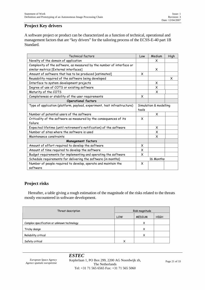
Project Key drivers
A software project or product can be characterized as a function of technical, operational and management factors that are “key drivers” for the tailoring process of the ECSS-E-40 part 1B Standard.
Technical factors Low Medium High
Novelty of the domain of application X Complexity of the software, as measured by the number of interface or similar metrics [External interfaces]
X
Amount of software that has to be produced [estimated] X Reusability required of the software being developed X Interface to system development projects X Degree of use of COTS or existing software X Maturity of the COTS X Completeness or stability of the user requirements X
Operational factors Type of application (platform, payload, experiment, test infrastructure) Simulation & modelling
tools Number of potential users of the software X Criticality of the software as measured by the consequences of its failure
X
Expected lifetime (until retirement’s notification) of the software X Number of sites where the software is used X Maintenance constraints X
Management factors Amount of effort required to develop the software X Amount of time required to develop the software X Budget requirements for implementing and operating the software X Schedule requirements for delivering the software (in months) 16 Months Number of people required to develop, operate and maintain the software
X
Project risks
Hereafter, a table giving a rough estimation of the magnitude of the risks related to the threats mostly encountered in software development.
Risk magnitude Threat description
LOW MEDIUM HIGH
Complex specification or unknown technology X
Tricky design X
Reliability critical X
Safety critical X
Statement of Work Issue: 1 Definition and Prototyping of an Autonomous Image Processing Chain Revision: 3 Date: 12/04/2007
European Space Agency Agence spatiale européenne
ESTEC Keplerlaan 1, PO Box 299, 2200 AG Noordwijk zh,
The Netherlands Tel: +31 71 565 6565 Fax: +31 71 565 5060
Page 22 of 33
Risk magnitude Threat description
LOW MEDIUM HIGH
Long term use X
Supplier’s background experience and maturity N/A
Potential lack of computers resources (processing time & memory) X
Potential lack of real time performances X
Roles
• The Customer is ESA • The Supplier is the selected contractor • The User is ESA • The Maintainer is the selected contractor who has designed and developed the system during
the 6 months’ warranty period • There is no operator in the frame of this contract (with respect to the operator definition in E40
part 1)
Processes involved
The following software processes are part of this project:
System engineering processes related to software
In this process the contractor:
• capture the model requirements in specifying the models characteristics, the accuracy and fidelity level, the data sources, the development constraints (if any) and the general performances
• describe the most appropriate “Modelling & Simulation” System Architecture (system breakdown and interfaces with others systems or equipments, and possibly COTS or reused software items (e.g. OS, MMI generator, 2D/3D representation, GIS)
• support the model definition requirements in performing, in the literature, an extensive survey of existing approaches, models and/or available experimental data
• define the theoretical model (e.g. mathematical description of the physical law, assumptions, simplifications and assessed limitations) and its computational algorithm (e.g. simulation/calculation methods, input data range, singularities in the transition regions)
• validate or verify by analysis the consistency, coherency and feasibility of the model requirements in terms of needed computers resources, memory and appropriateness of the computational algorithms (e.g. calculation methods)
Statement of Work Issue: 1 Definition and Prototyping of an Autonomous Image Processing Chain Revision: 3 Date: 12/04/2007
European Space Agency Agence spatiale européenne
ESTEC Keplerlaan 1, PO Box 299, 2200 AG Noordwijk zh,
The Netherlands Tel: +31 71 565 6565 Fax: +31 71 565 5060
Page 23 of 33
The software requirement and architecture engineering process,
In this process, the contractor provides the technical specifications of the software system to be implemented, mainly the model requirements allocated to the software items and, in that case:
• The specifications of the AIPC requirements, mainly, the data formats, the processing represented by the selected algorithms), and the accuracy and fidelity level
• The high-level interface control document • The software system breakdown into software components
The software design and implementation engineering process,
The software items are detailed designed, coded.
The software validation process
The software is validated, against the requirement baseline (System Requirements Document including interfaces requirements).
The software verification process,
At least for the establishment of the RB-TS /SVTS- SATS traceabilty matrices and probably also for the analyses and demonstration of the feasibility of intermediate work products (e.g. algorithms assessment reports, numerical accuracy)
The software delivery and acceptance process,
The software management process
Since the bidder will have to include, in its proposal, a draft development plan (including organization breakdown structure, work breakdown structure, life cycle, development methods and tools, reused software products, documentation to be produced, risk management, milestones, and deliveries).
The software maintenance process
Since this contract covers implicitly the corrective maintenance activities to be performed during the 6 months warranty period.
The following software processes are not part of this project (e.g.): • The software operation process as no helpdesk is necessary to operate this software in the
frame of this contract.
Statement of Work Issue: 1 Definition and Prototyping of an Autonomous Image Processing Chain Revision: 3 Date: 12/04/2007
European Space Agency Agence spatiale européenne
ESTEC Keplerlaan 1, PO Box 299, 2200 AG Noordwijk zh,
The Netherlands Tel: +31 71 565 6565 Fax: +31 71 565 5060
Page 24 of 33
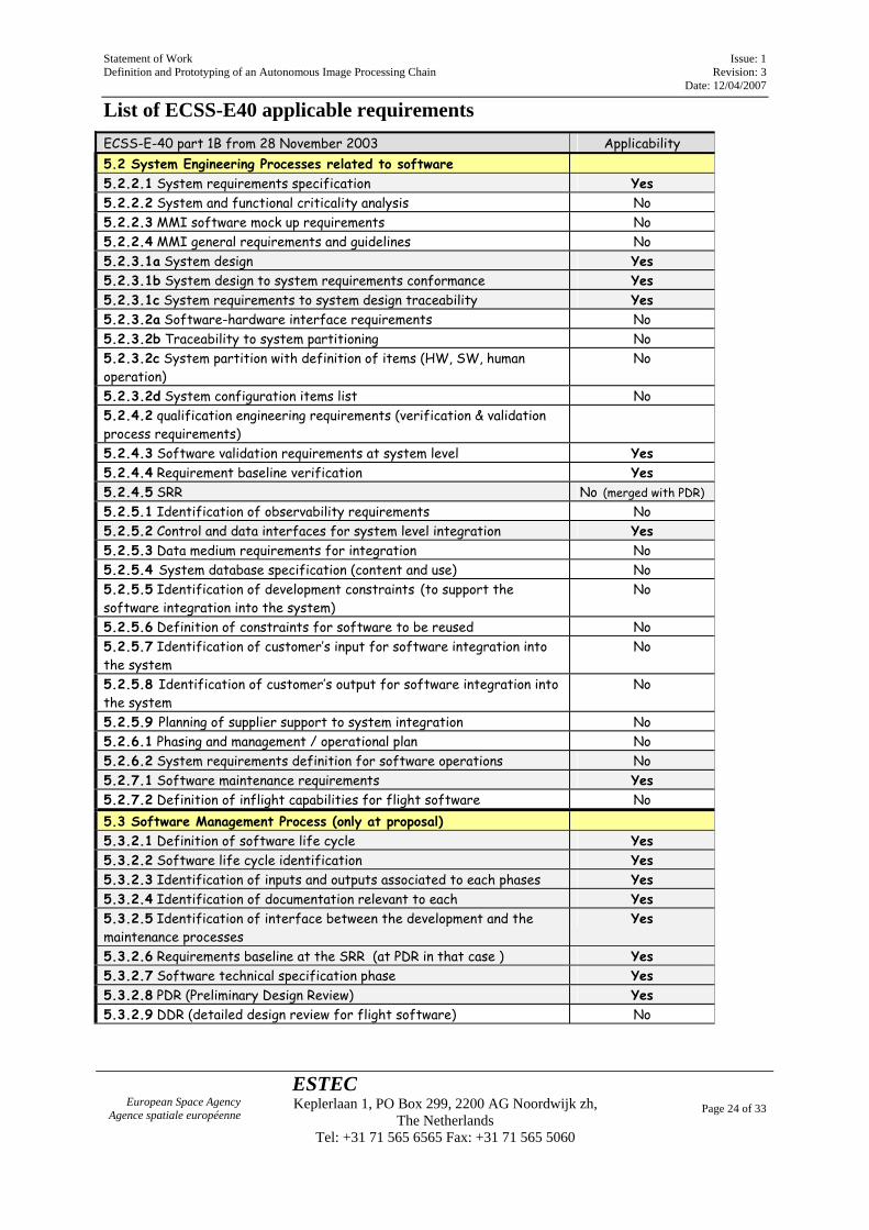
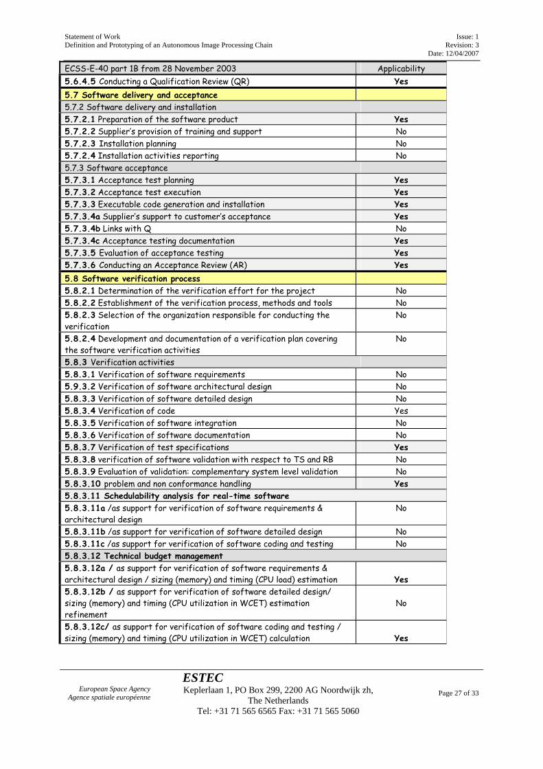
List of ECSS-E40 applicable requirements ECSS-E-40 part 1B from 28 November 2003 Applicability 5.2 System Engineering Processes related to software 5.2.2.1 System requirements specification Yes 5.2.2.2 System and functional criticality analysis No 5.2.2.3 MMI software mock up requirements No 5.2.2.4 MMI general requirements and guidelines No 5.2.3.1a System design Yes 5.2.3.1b System design to system requirements conformance Yes 5.2.3.1c System requirements to system design traceability Yes 5.2.3.2a Software-hardware interface requirements No 5.2.3.2b Traceability to system partitioning No 5.2.3.2c System partition with definition of items (HW, SW, human operation)
No
5.2.3.2d System configuration items list No 5.2.4.2 qualification engineering requirements (verification & validation process requirements)
5.2.4.3 Software validation requirements at system level Yes 5.2.4.4 Requirement baseline verification Yes 5.2.4.5 SRR No (merged with PDR) 5.2.5.1 Identification of observability requirements No 5.2.5.2 Control and data interfaces for system level integration Yes 5.2.5.3 Data medium requirements for integration No 5.2.5.4 System database specification (content and use) No 5.2.5.5 Identification of development constraints (to support the software integration into the system)
No
5.2.5.6 Definition of constraints for software to be reused No 5.2.5.7 Identification of customer’s input for software integration into the system
No
5.2.5.8 Identification of customer’s output for software integration into the system
No
5.2.5.9 Planning of supplier support to system integration No 5.2.6.1 Phasing and management / operational plan No 5.2.6.2 System requirements definition for software operations No 5.2.7.1 Software maintenance requirements Yes 5.2.7.2 Definition of inflight capabilities for flight software No 5.3 Software Management Process (only at proposal) 5.3.2.1 Definition of software life cycle Yes 5.3.2.2 Software life cycle identification Yes 5.3.2.3 Identification of inputs and outputs associated to each phases Yes 5.3.2.4 Identification of documentation relevant to each Yes 5.3.2.5 Identification of interface between the development and the maintenance processes
Yes
5.3.2.6 Requirements baseline at the SRR (at PDR in that case ) Yes 5.3.2.7 Software technical specification phase Yes 5.3.2.8 PDR (Preliminary Design Review) Yes 5.3.2.9 DDR (detailed design review for flight software) No
Statement of Work Issue: 1 Definition and Prototyping of an Autonomous Image Processing Chain Revision: 3 Date: 12/04/2007
European Space Agency Agence spatiale européenne
ESTEC Keplerlaan 1, PO Box 299, 2200 AG Noordwijk zh,
The Netherlands Tel: +31 71 565 6565 Fax: +31 71 565 5060
Page 25 of 33
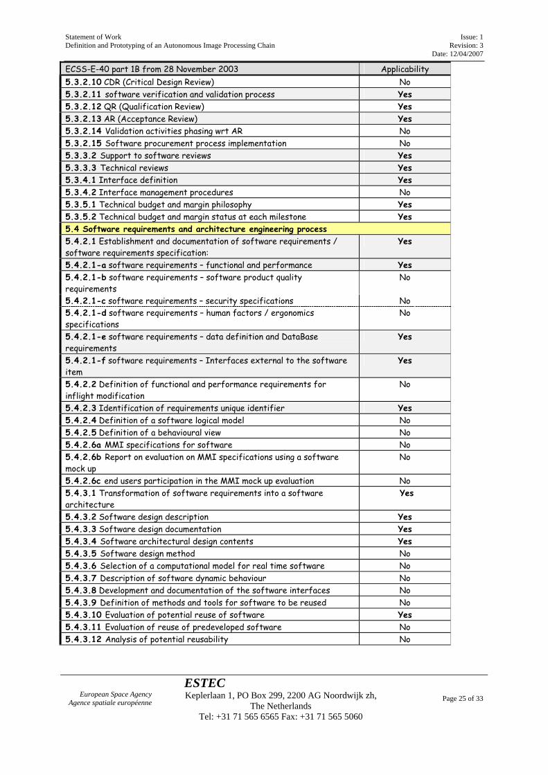
ECSS-E-40 part 1B from 28 November 2003 Applicability 5.3.2.10 CDR (Critical Design Review) No 5.3.2.11 software verification and validation process Yes 5.3.2.12 QR (Qualification Review) Yes 5.3.2.13 AR (Acceptance Review) Yes 5.3.2.14 Validation activities phasing wrt AR No 5.3.2.15 Software procurement process implementation No 5.3.3.2 Support to software reviews Yes 5.3.3.3 Technical reviews Yes 5.3.4.1 Interface definition Yes 5.3.4.2 Interface management procedures No 5.3.5.1 Technical budget and margin philosophy Yes 5.3.5.2 Technical budget and margin status at each milestone Yes 5.4 Software requirements and architecture engineering process 5.4.2.1 Establishment and documentation of software requirements / software requirements specification:
Yes
5.4.2.1-a software requirements – functional and performance Yes 5.4.2.1-b software requirements – software product quality requirements
No
5.4.2.1-c software requirements – security specifications No 5.4.2.1-d software requirements – human factors / ergonomics specifications
No
5.4.2.1-e software requirements – data definition and DataBase requirements
Yes
5.4.2.1-f software requirements – Interfaces external to the software item
Yes
5.4.2.2 Definition of functional and performance requirements for inflight modification
No
5.4.2.3 Identification of requirements unique identifier Yes 5.4.2.4 Definition of a software logical model No 5.4.2.5 Definition of a behavioural view No 5.4.2.6a MMI specifications for software No 5.4.2.6b Report on evaluation on MMI specifications using a software mock up
No
5.4.2.6c end users participation in the MMI mock up evaluation No 5.4.3.1 Transformation of software requirements into a software architecture
Yes
5.4.3.2 Software design description Yes 5.4.3.3 Software design documentation Yes 5.4.3.4 Software architectural design contents Yes 5.4.3.5 Software design method No 5.4.3.6 Selection of a computational model for real time software No 5.4.3.7 Description of software dynamic behaviour No 5.4.3.8 Development and documentation of the software interfaces No 5.4.3.9 Definition of methods and tools for software to be reused No 5.4.3.10 Evaluation of potential reuse of software Yes 5.4.3.11 Evaluation of reuse of predeveloped software No 5.4.3.12 Analysis of potential reusability No
Statement of Work Issue: 1 Definition and Prototyping of an Autonomous Image Processing Chain Revision: 3 Date: 12/04/2007
European Space Agency Agence spatiale européenne
ESTEC Keplerlaan 1, PO Box 299, 2200 AG Noordwijk zh,
The Netherlands Tel: +31 71 565 6565 Fax: +31 71 565 5060
Page 26 of 33
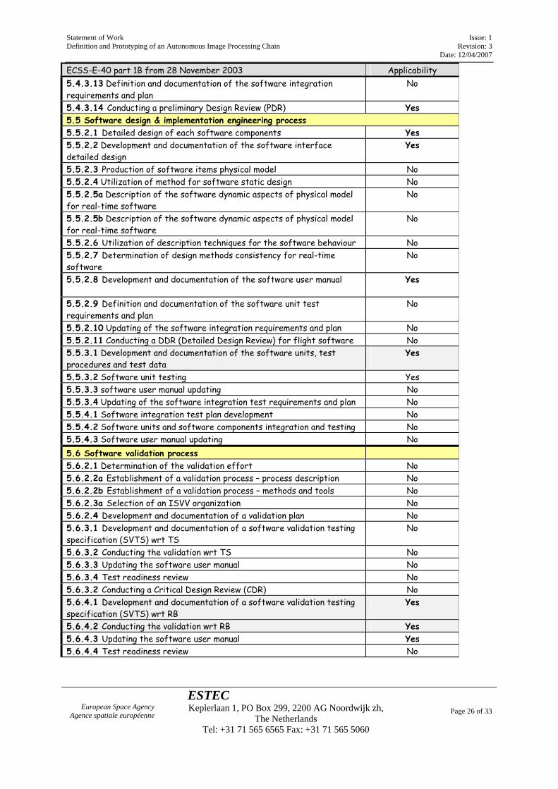
ECSS-E-40 part 1B from 28 November 2003 Applicability 5.4.3.13 Definition and documentation of the software integration requirements and plan
No
5.4.3.14 Conducting a preliminary Design Review (PDR) Yes 5.5 Software design & implementation engineering process 5.5.2.1 Detailed design of each software components Yes 5.5.2.2 Development and documentation of the software interface detailed design
Yes
5.5.2.3 Production of software items physical model No 5.5.2.4 Utilization of method for software static design No 5.5.2.5a Description of the software dynamic aspects of physical model for real-time software
No
5.5.2.5b Description of the software dynamic aspects of physical model for real-time software
No
5.5.2.6 Utilization of description techniques for the software behaviour No 5.5.2.7 Determination of design methods consistency for real-time software
No
5.5.2.8 Development and documentation of the software user manual Yes
5.5.2.9 Definition and documentation of the software unit test requirements and plan
No
5.5.2.10 Updating of the software integration requirements and plan No 5.5.2.11 Conducting a DDR (Detailed Design Review) for flight software No 5.5.3.1 Development and documentation of the software units, test procedures and test data
Yes
5.5.3.2 Software unit testing Yes 5.5.3.3 software user manual updating No 5.5.3.4 Updating of the software integration test requirements and plan No 5.5.4.1 Software integration test plan development No 5.5.4.2 Software units and software components integration and testing No 5.5.4.3 Software user manual updating No 5.6 Software validation process 5.6.2.1 Determination of the validation effort No 5.6.2.2a Establishment of a validation process – process description No 5.6.2.2b Establishment of a validation process – methods and tools No 5.6.2.3a Selection of an ISVV organization No 5.6.2.4 Development and documentation of a validation plan No 5.6.3.1 Development and documentation of a software validation testing specification (SVTS) wrt TS
No
5.6.3.2 Conducting the validation wrt TS No 5.6.3.3 Updating the software user manual No 5.6.3.4 Test readiness review No 5.6.3.2 Conducting a Critical Design Review (CDR) No 5.6.4.1 Development and documentation of a software validation testing specification (SVTS) wrt RB
Yes
5.6.4.2 Conducting the validation wrt RB Yes 5.6.4.3 Updating the software user manual Yes 5.6.4.4 Test readiness review No
Statement of Work Issue: 1 Definition and Prototyping of an Autonomous Image Processing Chain Revision: 3 Date: 12/04/2007
European Space Agency Agence spatiale européenne
ESTEC Keplerlaan 1, PO Box 299, 2200 AG Noordwijk zh,
The Netherlands Tel: +31 71 565 6565 Fax: +31 71 565 5060
Page 27 of 33
ECSS-E-40 part 1B from 28 November 2003 Applicability 5.6.4.5 Conducting a Qualification Review (QR) Yes 5.7 Software delivery and acceptance 5.7.2 Software delivery and installation 5.7.2.1 Preparation of the software product Yes 5.7.2.2 Supplier’s provision of training and support No 5.7.2.3 Installation planning No 5.7.2.4 Installation activities reporting No 5.7.3 Software acceptance 5.7.3.1 Acceptance test planning Yes 5.7.3.2 Acceptance test execution Yes 5.7.3.3 Executable code generation and installation Yes 5.7.3.4a Supplier’s support to customer’s acceptance Yes 5.7.3.4b Links with Q No 5.7.3.4c Acceptance testing documentation Yes 5.7.3.5 Evaluation of acceptance testing Yes 5.7.3.6 Conducting an Acceptance Review (AR) Yes 5.8 Software verification process 5.8.2.1 Determination of the verification effort for the project No 5.8.2.2 Establishment of the verification process, methods and tools No 5.8.2.3 Selection of the organization responsible for conducting the verification
No
5.8.2.4 Development and documentation of a verification plan covering the software verification activities
No
5.8.3 Verification activities 5.8.3.1 Verification of software requirements No 5.9.3.2 Verification of software architectural design No 5.8.3.3 Verification of software detailed design No 5.8.3.4 Verification of code Yes 5.8.3.5 Verification of software integration No 5.8.3.6 Verification of software documentation No 5.8.3.7 Verification of test specifications Yes 5.8.3.8 verification of software validation with respect to TS and RB No 5.8.3.9 Evaluation of validation: complementary system level validation No 5.8.3.10 problem and non conformance handling Yes 5.8.3.11 Schedulability analysis for real-time software 5.8.3.11a /as support for verification of software requirements & architectural design
No
5.8.3.11b /as support for verification of software detailed design No 5.8.3.11c /as support for verification of software coding and testing No 5.8.3.12 Technical budget management 5.8.3.12a / as support for verification of software requirements & architectural design / sizing (memory) and timing (CPU load) estimation
Yes
5.8.3.12b / as support for verification of software detailed design/ sizing (memory) and timing (CPU utilization in WCET) estimation refinement
No
5.8.3.12c/ as support for verification of software coding and testing / sizing (memory) and timing (CPU utilization in WCET) calculation
Yes
Statement of Work Issue: 1 Definition and Prototyping of an Autonomous Image Processing Chain Revision: 3 Date: 12/04/2007
European Space Agency Agence spatiale européenne
ESTEC Keplerlaan 1, PO Box 299, 2200 AG Noordwijk zh,
The Netherlands Tel: +31 71 565 6565 Fax: +31 71 565 5060
Page 28 of 33
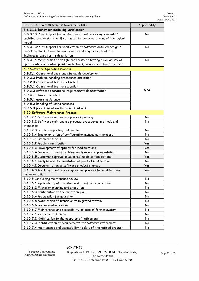
ECSS-E-40 part 1B from 28 November 2003 Applicability 5.8.3.13 Behaviour modelling verification 5.8.3.13a/ as support for verification of software requirements & architectural design / verification of the behavioural view of the logical model
No
5.8.3.13b/ as support for verification of software detailed design / modelling the software behaviour and verifying by means of the techniques used for its description
No
5.8.3.14 Verification of design: feasibility of testing / availability of appropriate verification points, assertions, capability of fault injection
No
5.9 Software Operation Process 5.9.2.1 Operational plans and standards development 5.9.2.2 Problem handling procedures definition 5.9.2.3 Operational testing definition 5.9.3.1 Operational testing execution 5.9.3.2 software operational requirements demonstration 5.9.4 software operation 5.9.5.1 user’s assistance 5.9.5.2 handling of user’s requests 5.9.5.3 provisions of work-around solutions
N/A
5.10 Software Maintenance Process 5.10.2.1 Software maintenance process planning No 5.10.2.2 Software maintenance process: procedures, methods and standards
No
5.10.2.3 problem reporting and handling No 5.10.2.4 Implementation of configuration management process No 5.10.3.1 Problem analysis No 5.10.3.2 Problem verification Yes 5.10.3.3 Development of options for modifications Yes 5.10.3.4 Documentation of problem, analysis and implementation No 5.10.3.5 Customer approval of selected modifications options Yes 5.10.4.1 Analysis and documentation of product modification No 5.10.4.2 Documentation of software product changes Yes 5.10.4.3 Invoking of software engineering process for modification implementation
Yes
5.10.5 Conducting maintenance review No 5.10.6.1 Applicability of this standard to software migration No 5.10.6.2 Migration planning and execution No 5.10.6.3 Contribution to the migration plan No 5.10.6.4 Preparation for migration No 5.10.6.5 Notification of transition to migrated system No 5.10.6.6 Post-operation review No 5.10.6.7 Maintenance and accessibility of data of former system No 5.10.7.1 Retirement planning No 5.10.7.2 Notification to the operator of retirement No 5.10.7.3 identification of requirements for software retirement No 5.10.7.4 maintenance and accessibility to data of the retired product No
Statement of Work Issue: 1 Definition and Prototyping of an Autonomous Image Processing Chain Revision: 3 Date: 12/04/2007
European Space Agency Agence spatiale européenne
ESTEC Keplerlaan 1, PO Box 299, 2200 AG Noordwijk zh,
The Netherlands Tel: +31 71 565 6565 Fax: +31 71 565 5060
Page 29 of 33
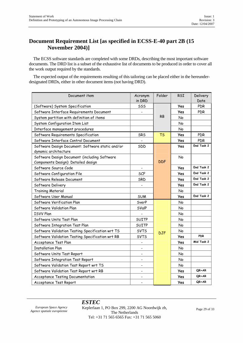
Document Requirement List [as specified in ECSS-E-40 part 2B (15 November 2004)]
The ECSS software standards are completed with some DRDs, describing the most important software documents. The DRD list is a subset of the exhaustive list of documents to be produced in order to cover all the work output required by the standards.
The expected output of the requirements resulting of this tailoring can be placed either in the hereunder-designated DRDs, either in other document items (not having DRD).
Document item Acronym
in DRD Folder RSI Delivery
Date (Software) System Specification SSS Yes PDR Software Interface Requirements Document - Yes PDR System partition with definition of items No System Configuration Item List No Interface management procedures
RB
No Software Requirements Specification SRS Yes PDR Software Interface Control Document -
TS Yes PDR
Software Design Document: Software static and/or dynamic architecture
SDD Yes End Task 2
Software Design Document (including Software Components Design): Detailed design
No
Software Source Code - Yes End Task 2
Software Configuration File SCF Yes End Task 2
Software Release Document SRD Yes End Task 2
Software Delivery - Yes End Task 2
Training Material No Software User Manual SUM
DDF
Yes End Task 2
Software Verification Plan SverP No Software Validation Plan SValP No ISVV Plan - No Software Units Test Plan SUITP No Software Integration Test Plan SUITP No Software Validation Testing Specification wrt TS SVTS No Software Validation Testing Specification wrt RB SVTS Yes PDR
Acceptance Test Plan - Yes Mid Task 2
Installation Plan - No Software Units Test Report - No Software Integration Test Report - No Software Validation Test Report wrt TS - No Software Validation Test Report wrt RB - Yes QR+AR
Acceptance Testing Documentation - Yes QR+AR
Acceptance Test Report -
DJF
Yes QR+AR
Statement of Work Issue: 1 Definition and Prototyping of an Autonomous Image Processing Chain Revision: 3 Date: 12/04/2007
European Space Agency Agence spatiale européenne
ESTEC Keplerlaan 1, PO Box 299, 2200 AG Noordwijk zh,
The Netherlands Tel: +31 71 565 6565 Fax: +31 71 565 5060
Page 30 of 33
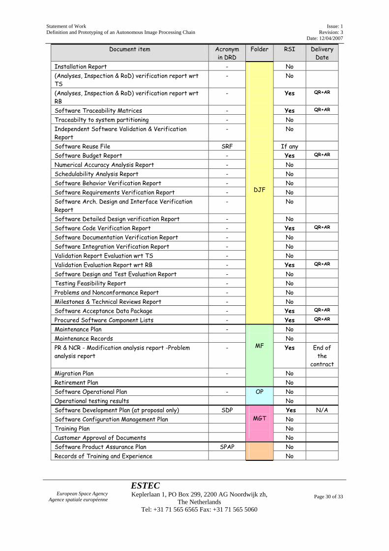
Document item Acronym in DRD
Folder RSI Delivery Date
Installation Report - No (Analyses, Inspection & RoD) verification report wrt TS
- No
(Analyses, Inspection & RoD) verification report wrt RB
- Yes QR+AR
Software Traceability Matrices - Yes QR+AR
Traceabilty to system partitioning - No Independent Software Validation & Verification Report
- No
Software Reuse File SRF If any Software Budget Report - Yes QR+AR
Numerical Accuracy Analysis Report - No Schedulability Analysis Report - No Software Behavior Verification Report - No Software Requirements Verification Report - No Software Arch. Design and Interface Verification Report
- No
Software Detailed Design verification Report - No Software Code Verification Report - Yes QR+AR
Software Documentation Verification Report - No Software Integration Verification Report - No Validation Report Evaluation wrt TS - No Validation Evaluation Report wrt RB - Yes QR+AR
Software Design and Test Evaluation Report - No Testing Feasibility Report - No Problems and Nonconformance Report - No Milestones & Technical Reviews Report - No Software Acceptance Data Package - Yes QR+AR
Procured Software Component Lists -
DJF
Yes QR+AR
Maintenance Plan - No Maintenance Records No PR & NCR - Modification analysis report -Problem analysis report
- Yes End of the
contract Migration Plan - No Retirement Plan
MF
No Software Operational Plan - No Operational testing results
OP No
Software Development Plan (at proposal only) SDP Yes N/A Software Configuration Management Plan No Training Plan No Customer Approval of Documents
MGT
No
Software Product Assurance Plan SPAP No Records of Training and Experience
No
Statement of Work Issue: 1 Definition and Prototyping of an Autonomous Image Processing Chain Revision: 3 Date: 12/04/2007
European Space Agency Agence spatiale européenne
ESTEC Keplerlaan 1, PO Box 299, 2200 AG Noordwijk zh,
The Netherlands Tel: +31 71 565 6565 Fax: +31 71 565 5060
Page 31 of 33
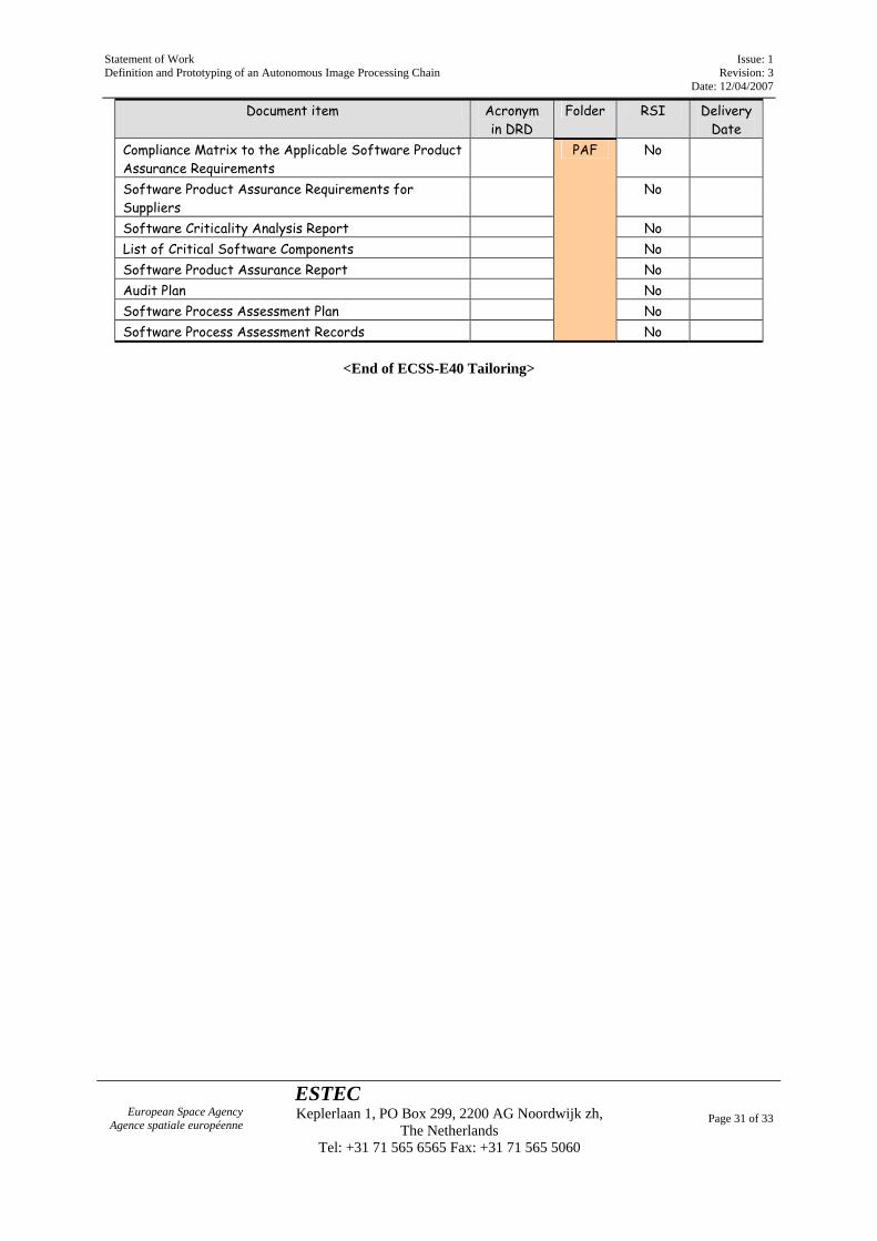
Document item Acronym in DRD
Folder RSI Delivery Date
Compliance Matrix to the Applicable Software Product Assurance Requirements
No
Software Product Assurance Requirements for Suppliers
No
Software Criticality Analysis Report No List of Critical Software Components No Software Product Assurance Report No Audit Plan No Software Process Assessment Plan No Software Process Assessment Records
PAF
No
<End of ECSS-E40 Tailoring>
Statement of Work Issue: 1 Definition and Prototyping of an Autonomous Image Processing Chain Revision: 3 Date: 12/04/2007
European Space Agency Agence spatiale européenne
ESTEC Keplerlaan 1, PO Box 299, 2200 AG Noordwijk zh,
The Netherlands Tel: +31 71 565 6565 Fax: +31 71 565 5060
Page 32 of 33
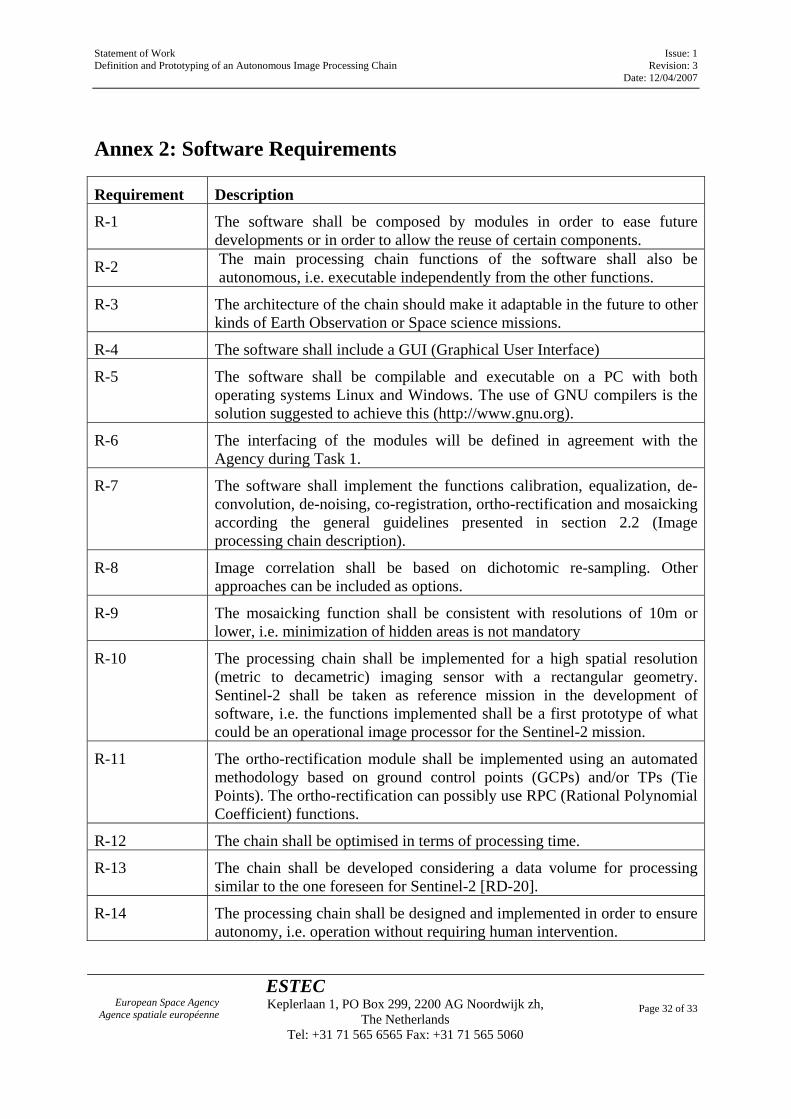
Annex 2: Software Requirements
Requirement Description
R-1 The software shall be composed by modules in order to ease future developments or in order to allow the reuse of certain components.
R-2 The main processing chain functions of the software shall also be autonomous, i.e. executable independently from the other functions.
R-3 The architecture of the chain should make it adaptable in the future to other kinds of Earth Observation or Space science missions.
R-4 The software shall include a GUI (Graphical User Interface)
R-5 The software shall be compilable and executable on a PC with both operating systems Linux and Windows. The use of GNU compilers is the solution suggested to achieve this (http://www.gnu.org).
R-6 The interfacing of the modules will be defined in agreement with the Agency during Task 1.
R-7 The software shall implement the functions calibration, equalization, de-convolution, de-noising, co-registration, ortho-rectification and mosaicking according the general guidelines presented in section 2.2 (Image processing chain description).
R-8 Image correlation shall be based on dichotomic re-sampling. Other approaches can be included as options.
R-9 The mosaicking function shall be consistent with resolutions of 10m or lower, i.e. minimization of hidden areas is not mandatory
R-10 The processing chain shall be implemented for a high spatial resolution (metric to decametric) imaging sensor with a rectangular geometry. Sentinel-2 shall be taken as reference mission in the development of software, i.e. the functions implemented shall be a first prototype of what could be an operational image processor for the Sentinel-2 mission.
R-11 The ortho-rectification module shall be implemented using an automated methodology based on ground control points (GCPs) and/or TPs (Tie Points). The ortho-rectification can possibly use RPC (Rational Polynomial Coefficient) functions.
R-12 The chain shall be optimised in terms of processing time.
R-13 The chain shall be developed considering a data volume for processing similar to the one foreseen for Sentinel-2 [RD-20].
R-14 The processing chain shall be designed and implemented in order to ensure autonomy, i.e. operation without requiring human intervention.
Statement of Work Issue: 1 Definition and Prototyping of an Autonomous Image Processing Chain Revision: 3 Date: 12/04/2007
European Space Agency Agence spatiale européenne
ESTEC Keplerlaan 1, PO Box 299, 2200 AG Noordwijk zh,
The Netherlands Tel: +31 71 565 6565 Fax: +31 71 565 5060
Page 33 of 33
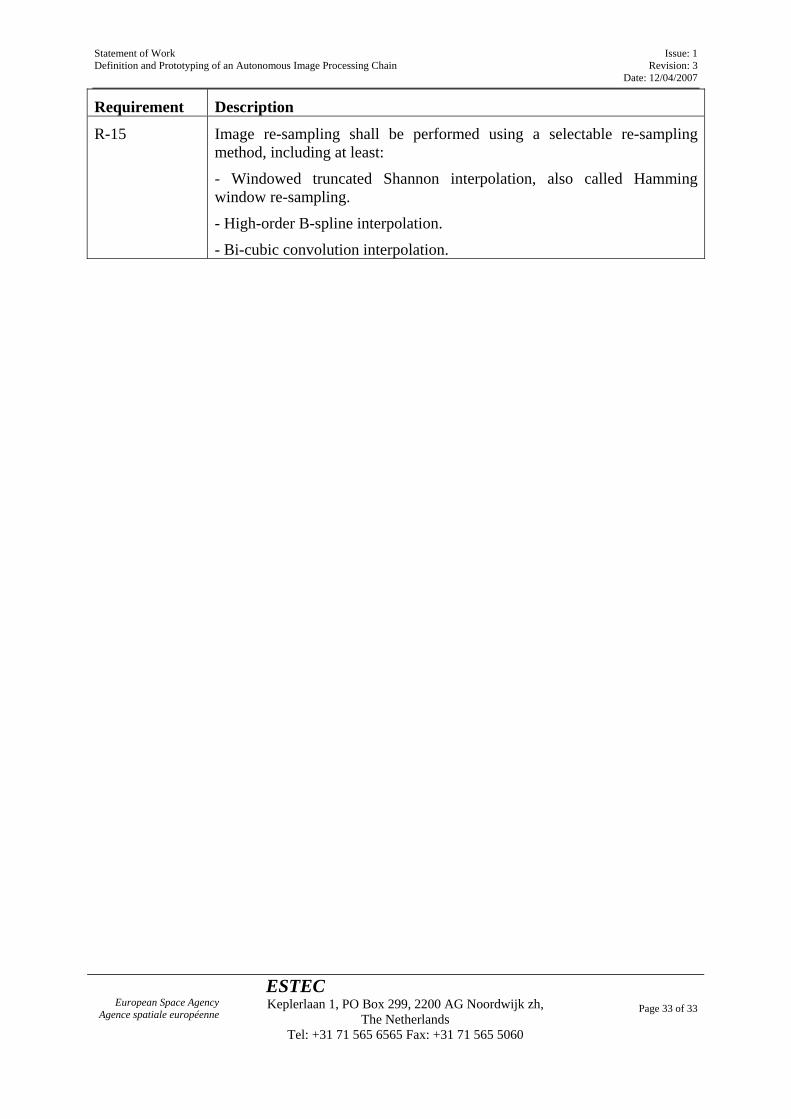
Requirement Description
R-15 Image re-sampling shall be performed using a selectable re-sampling method, including at least:
- Windowed truncated Shannon interpolation, also called Hamming window re-sampling.
- High-order B-spline interpolation.
- Bi-cubic convolution interpolation.


![Sx, Ama Supercross 2015 Live Stream Atlanta,Ga Rd8 Online [2015 Atlanta Supercross Live Stream]](https://img.pdfslide.us/doc/110x75/55ab252f1a28ab3f608b46a8/sx-ama-supercross-2015-live-stream-atlantaga-rd8-online-2015-atlanta-supercross-live-stream.jpg)