Embed Size (px)
Citation preview

EUR DOC 012
EUROPEAN GUIDANCE MATERIAL ON
CONTINUITY OF SERVICE EVALUATION IN SUPPORT OF
THE CERTIFICATION OF ILS & MLS GROUND SYSTEMS
Second Edition PREPARED BY THE EUROPEAN AND NORTH ATLANTIC OFFICE OF ICAO November 2019

THE DESIGNATIONS AND THE PRESENTATION OF MATERIAL IN THIS PUBLICATION DO NOT IMPLY THE EXPRESSION OF ANY OPINION WHATSOEVER ON THE PART OF ICAO CONCERNING THE LEGAL STATUS OF ANY COUNTRY, TERRITORY, CITY OR AREA OF ITS AUTHORITIES, OR CONCERNING THE DELIMITATION OF ITS FRONTIERS OR BOUNDARIES.
EUROPEAN AND NORTH ATLANTIC OFFICE OF ICAO
International Civil Aviation Organization (ICAO) European and North Atlantic (EUR/NAT) Office
3 bis, Villa Emile Bergerat 92522, Neuilly-sur-Seine CEDEX
FRANCE
e-mail : [email protected] Tel : +33 1 46 41 85 85 Fax : +33 1 46 41 85 00 Web : http://www.icao.int/EURNAT

CONTENTS
RECORD OF AMENDMENTS ................................................................................................... 1 1 INTRODUCTION ................................................................................................................. 2 2 SCOPE .................................................................................................................................. 2 3 DEFINITIONS ...................................................................................................................... 2 4 ABBREVIATIONS ............................................................................................................... 2 5 CERTIFICATION OF NEW SYSTEM TYPES .................................................................... 3 5.1 Introduction ........................................................................................................................ 3 5.2 Type Approval .................................................................................................................... 3
5.2.1 Design Approval........................................................................................................... 3 5.2.2 Operational Evaluation ................................................................................................. 3
5.2.2.1 Continuity of Service Evaluation ............................................................................ 4 5.2.2.1.1 Continuity of Service Evaluation for Multiple Identical New Systems (Class) ..... 4
5.2.3 Manufacture Quality and Support Procedures ............................................................... 4 5.3 Installation Approval ........................................................................................................... 4 6 CERTIFICATION OF SUBSEQUENT SYSTEMS ............................................................... 4 6.1 Introduction ........................................................................................................................ 4 6.2 Factory Tests ...................................................................................................................... 5 6.3 Operational Evaluation........................................................................................................ 5
6.3.1 Continuity of Service .................................................................................................... 5 7 POST CERTIFICATION CONTINUITY OF SERVICE MONITORING ............................. 6 8 RESTORATION TO SERVICE OF REPAIRED AND/OR MODIFIED SYSTEMS ............. 7 8.1 Replacement of identical components: ................................................................................. 7 8.2 Modifications of the system................................................................................................. 7 9 PRE-REQUISITES FOR A DEMONSTRATION OF CONTINUITY OF SERVICE ............ 8 10 REFERENCES ................................................................................................................... 9 APPENDIX A - RELIABILITY DEMONSTRATION USING SEQUENTIAL TEST PLANS . 11 A.1 Reliability Demonstrations ................................................................................................ 11 A.2 Definitions ........................................................................................................................ 11 A.3 Reliability Test Plans ......................................................................................................... 12
A.3.1 Example 60% Confidence Test ................................................................................... 13 A.3.1.1 Operating Characteristics .................................................................................... 14 A.3.1.2 Confidence Limits .................................................................................................... 16
A.3.2 Example 90% Confidence Test ................................................................................... 17 A.3.2.2 Operating Curves ..................................................................................................... 20 A.3.2.3 Confidence Limits .................................................................................................... 21
APPENDIX B - CUMULATIVE OPERATING TIME APPROACH ......................................... 23 B.1 BACKGROUND .............................................................................................................. 23 B.2 NEW SYSTEMS .............................................................................................................. 23
B.2.1 Outlier Detection ........................................................................................................ 25 APPENDIX C - POST-CERTIFICATION RELIABILITY MONITORING .............................. 26 C.1 INTRODUCTION ............................................................................................................ 26
C.1.1 Monitor Initialization .................................................................................................. 27

Page 1 of 28 Second Edition: November 2019
RECORD OF AMENDMENTS
EUROPEAN GUIDANCE MATERIAL ON CONTINUITY OF SERVICE EVALUATION IN SUPPORT OF THE CERTIFICATION OF ILS & MLS GROUND SYSTEMS
Paragraph(s) Explanation
1st Edition
2nd Edition
Chapter 5, paragraphs 5.2, 5.2.2, 5.2.2.1 and 5.2.2.1.1 Chapter 6 paragraphs 6.1, 6.3 and 6.3.1, Chapter 10 Appendix A paragraphs A.2 and A.3.1 Appendix C paragraphs C.1
Approved by EANPG COG/75 & RASG-EUR RCOG/12 Combined Meeting

Page 2 of 28 Second Edition: November 2019
1 INTRODUCTION
The objective of this document is to provide guidance on basic methods that may be applied by States to enable the common certification of ILS & MLS ground systems in Europe. The intention is that States will be able to accept the certification processes carried out by other co-operating States and may be able to carry out joint reliability proving tests. This should result in less duplication of work, and more effective methods of putting new systems into service.
Certification includes both an assessment of integrity and an evaluation of continuity of service. Both requirements have to be satisfied for the system to be certified. As an initial step in the development of European Guidance material, this document mainly focuses on the evaluation of continuity of service.
2 SCOPE
This document provides guidance on:
• Systems that are not yet in use in any of the co-operating States. • Systems used by some States but being introduced for the first time to another
State. • Further similar systems being put into service within a State. • Restoration to service of repaired or modified system. • Post certification monitoring.
3 DEFINITIONS
Reliability: The probability that a system will operate within the specified tolerances.
Integrity: The probability that a system will not radiate incorrect navigation guidance information.
Continuity of Service: The probability that a system will not fail to radiate navigation guidance information during a defined time interval.
Outage: The failure of a system to radiate navigation guidance.
Class: A group of systems whose cumulative operating time and associated outages can be considered as originating from one individual system.
Subsequent System: A system identical to a type that has been previously certified.
4 ABBREVIATIONS
FMECA Failure Modes, Effects and Criticality Analysis ICAO International Civil Aviation Organization ILS Instrument Landing System MLS Microwave Landing System MTBF Mean Time Between Failures MTBO Mean Time Between Outages SARPs Standards and Recommended Practices

Page 3 of 28 Second Edition: November 2019
5 CERTIFICATION OF NEW SYSTEM TYPES
5.1 Introduction
A New System Type refers to a type of installation not yet in use in any co-operating state.
5.2 Type Approval
Type approval is a series of tests and verifications which are normally only performed once for a particular build state or design of system. The type approval process also includes an assessment of the manufacturer’s quality and support procedures to ensure controlled and repeatable production techniques. Certain type approval tests may need to be repeated if the system is subsequently modified.
5.2.1 Design Approval
The manufacturer should provide evidence that the system meets all the non-site-specific requirements for the system. This may be a combination of demonstration results and theoretical analysis to demonstrate compliance with ICAO Annex 10 SARPs.
The manufacturer should provide an analysis showing that the theoretical continuity of service is at least twice that required in operational service.
The manufacturer should also provide an analysis showing that the integrity of the system meets the requirement for the intended category of use. As integrity cannot be verified by field tests, it is essential that this is verified by detailed analysis. This will normally be carried out using techniques such as Fault Tree Analysis and FMECA.
5.2.2 Operational Evaluation
For type approval testing, it is normal practice to install the system on a site that is reasonably clear of any obstructions which could affect the radiated signals.
Extensive ground and flight tests should be made to ensure that all parameters of the radiated signal are compliant with ICAO Annex 10 SARPs. Guidance for conducting these tests may be found in ICAO Doc 8071; guidance for evaluating the results is available in ICAO Doc 8071 and in the Attachments to ICAO Annex 10.These type approval tests will normally be more comprehensive than those carried out at commissioning. Such tests should be made at both extremes of the environmental conditions encountered in the State. Long term performance measurements should be made to determine the stability of key parameters in an operational environment.
Page 4 of 28 Second Edition: November 2019
5.2.2.1 Continuity of Service Evaluation
The Continuity of Service performance of a new system has not been established in an operational environment; it must therefore be demonstrated, to a high degree of confidence, that the system, or type of system, possesses the required reliability.
See Appendix A for details of methods of demonstration.
5.2.2.1.1 Continuity of Service Evaluation for Multiple Identical New Systems (Class)
Where several identical systems are being operated under similar conditions, it may be possible to base the operational evaluation of Continuity of Service on the cumulative operating hours of all the systems. This may result in a reduced evaluation period. Strict configuration controls are necessary to ensure that all systems are identical and that systems are installed, maintained and supported to a common standard. See Appendix B for details of continuity of service evaluation for a class of identical systems.
5.2.3 Manufacture Quality and Support Procedures
Adequate quality procedures and manufacturing practices must be applied during the build of a system. Evidence of a separate quality organization, appropriate inspection and test facilities will be required. Adequate configuration management systems must be in place, and for safety critical and safety related areas traceability to component source must be in place.
5.3 Installation Approval
For the certification of individual ground equipment installations additional site-specific factors must be considered, including equipment siting, ground test procedures and flight verification procedures.
6 CERTIFICATION OF SUBSEQUENT SYSTEMS
6.1 Introduction
The Certification of a Subsequent System refers to the certification of an installation of a previously certified type. Suitable certification procedures should reflect the a priori reliability knowledge of the system to be installed. The procedures described in this document put the onus on obtaining reliability knowledge in an operational environment, but once a type of system has been certified, if a subsequent identical system is installed and maintained to the same standard, a faster route can be justified. Systems certified in this way will initially be subject to a more stringent post-

Page 5 of 28 Second Edition: November 2019
certification monitoring system than for new systems, through the use of a more conservative initial MTBO value. See Appendix C for details.
6.2 Factory Tests
Before commencing the installation of any equipment, the manufacturer’s factory test results should be examined. If the tests are not witnessed by the customer’s representative, they should be approved by the manufacturer’s designated quality representative.
6.3 Operational Evaluation
For system certification of individual ground equipment installations, specific-to-site tests should be made. These are not part of a common certification process, but are to ensure the system’s radiated signals comply with ICAO Annex 10 SARPs when the equipment is installed on a particular site. Ground and flight tests should be made on each facility. Guidance for conducting these tests may be found in ICAO Doc 8071; guidance for evaluating the results is available in ICAO Doc 8071 and in the Attachments to ICAO Annex 10. In addition to these signal-in-space checks, additional tests are required including an evaluation of the continuity of service performance of the system at the chosen site.
6.3.1 Continuity of Service
Fast Track Approach:
The introduction of a subsequent system need not require a re-certification as if the system were new. A subsequent system of a type previously certified could be operational in a time significantly less than that required for the certification of a new system. The reliability demonstration requirement becomes more a requirement to demonstrate correct installation than a requirement to re-certify assuming no previous knowledge. A minimum time is proposed for the demonstration of correct installation of subsequent systems (typically one day for Cat I and 30 days for Cat II/III facilities). This fast-track route to subsequent system certification is dependent upon the degree of belief that the system to be installed possesses sufficient reliability. If substantial historic knowledge has been obtained from a number of systems in an operational environment, and if a significant variation in those systems’ reliability has not been observed the fast track-route may be applied. The sequential discordancy test performed during the certification of the group of systems can be used to assess whether a substantial variation in reliability has been observed. If the reduced confidence level of 60% is to be used for the initial certification of the system type, it is recommended that the fast-track route for the certification of subsequent systems be denied until it has been demonstrated that the Class type meets the reliability requirement with 90% confidence.

Page 6 of 28 Second Edition: November 2019
A subsequent system certified via the “fast-track” route will initially be subject to a more stringent post-certification monitoring system than for new systems, through the use of a more conservative initial MTBO value. See Appendix C for details. Intermediate Approach:
An intermediate approach is described which could be adopted if a degree of operational reliability knowledge has been gained, but the information is either limited in extent or has revealed evidence of significant variation in reliability between systems of that type. Under such circumstances a 60% confidence sequential test with the one-year minimum removed is recommended.
Subsequent System
IdenticalSystem ?
Yes
No
LimitedConfidence
Yes
No InstallationTest Passed
No
CertifiedSystem
SequentialTest
CertifiedSystem
RejectedSystem
Continue
Accept
Reject
Yes
Fig. 6-1: Certification of Subsequent Systems
7 POST CERTIFICATION CONTINUITY OF SERVICE MONITORING
Once a system is in service the MTBO should be continually monitored. A system showing a degradation in continuity of service may have to be operated at a lower category or withdrawn from service until the cause has been rectified and sufficient confidence has been gained.

Page 7 of 28 Second Edition: November 2019
For single equipment the MTBO equals the MTBF, but in dual systems which are commonly used for Category II/III operations the MTBO is not equal to the MTBF. Dual systems are used due to single equipment not being able to achieve the required MTBO and/or to increase the availability of the system. At first glance the MTBF may not look as important as the MTBO of the system. The MTBF requirement is not stated as such in the ICAO Annex 10, but if parts of the equipment not leading to an unanticipated interruption of the signal in space because the equipment switches over to the standby transmitter following a fault, result in a low MTBF of the system this may lead to a decrease of the integrity of the system. This is especially the case, when the individual monitor system parts have a low MTBF. For this reason the MTBF of the system should be continually monitored. Guidance on the application of Post Certification Monitoring is given in Appendix C.
8 RESTORATION TO SERVICE OF REPAIRED AND/OR MODIFIED SYSTEMS
Maintenance and repair to systems may range from minor component to full antenna and transmitter replacement as well as modifications of the system. The assessment of the impact of maintenance and repair to a system will require careful consideration as to the type of component and the function performed by it.
8.1 Replacement of identical components:
Following replacement of identical components a review of the installation is required. This is to ensure that the installation has stabilized and that other components have not been affected. Depending on the extent of repair work, a test period is recommended before restoring the system back to Category II or III operation. The length of this period is to be based on sound engineering judgement. If the failure occurred in a non-redundant part of the system or caused a signal outage, a minimum test period of 12 hours is suggested and it is recommended that 24 hours elapse prior to returning to Category II or III.
8.2 Modifications of the system
Modifications can range from minor changes to effectively a new system. The relative assessment of the change, taking into account the current regulations is a subjective decision based on sound engineering judgement. This may range from a requirement by the regulator for full re-certification, to a requirement to demonstrate the correct installation of the modified component. Any modification should be reviewed and approved by a designated body before re-introduction to service and phased re-classification in category of operation. This body may consist of a senior engineer, a board of engineers etc. who has not participated in design work of the modification.

Page 8 of 28 Second Edition: November 2019
In order to assess the influence the modification has on system performance, it is essential that the modification be carefully documented. This should include a proper test plan submitted to the designated body before commencing the tests.
9 PRE-REQUISITES FOR A DEMONSTRATION OF CONTINUITY OF SERVICE
Before beginning a reliability evaluation, all participating organizations should agree on the precise definition of failure and outage relevant to the evaluation. The participating organizations will normally include those responsible for manufacture, installation and operation of the system. Although failures may not cause outages, it is essential that they are all recorded since they may have an effect on integrity. If several systems are to be assessed as a class, small differences between the individual systems are permitted, provided that an analysis has shown these differences to be in areas which will not affect the expected MTBO or integrity. Failures/outages may be disregarded if they can be mitigated by: • Redesign of the affected area. • Change of manufacturing process. • Change of installation techniques. • Change of procedural methods.
In these cases, the change should be thoroughly analyzed to ensure that it has addressed the original cause of the failure and that it will have no detrimental effect on other areas. It is common practice to set up a “change control board” having members from all participating organizations, to agree on proposed changes and their effects. In most cases, identical changes should be applied to all equipment operating in the class and to all subsequent equipment. Procedural methods of mitigation may also be used, for example: If an equipment fails under heavy snowfall conditions, this type of failure can be removed from the analysis if the system is never operated under these conditions. E.g. a documented procedure should ensure that the equipment is always taken out of service when the snow reaches a certain depth.
Page 9 of 28 Second Edition: November 2019
10 REFERENCES
1 ICAO Annex 10 to the Convention on International Civil Aviation, Volume 1.
2 ICAO Doc. 8071 Manual on the Testing of Radio Navigation Aids, Volume I.
3 Eurocae ED53A Minimum Operational Performance Specification for MLS
Ground Equipment.
4 DERA/WSS/WX1/CR980799/2.3 ILS Certification Requirements, Final Report.
5 United States Department of Defense, MIL-HDBK-781A Handbook for
Reliability Test Methods, Plans and Environments for Engineering, Development, Qualification and Production

Page 10 of 28 Second Edition: November 2019
This page is intentionally blank

Page 11 of 28 Second Edition: November 2019
APPENDIX A - RELIABILITY DEMONSTRATION USING SEQUENTIAL TEST PLANS
A.1 Reliability Demonstrations
ICAO Annex 10 contains Continuity of Service requirements for the various Facility Performance Categories for ILS and MLS Ground equipments. Individual requirements for ground equipment used to support CAT II and CAT III operations have been incorporated under Amendment 74 together with additional guidance material provided in Attachments C and G to Part 1. An overview of the requirements is given in Table A1-1 below.
Category
MTBO = θ1 (Hours)
CAT I: (Recommendation only)
Localizer/Az 1000
Glide path/El 1000
CAT II & CAT IIIA
Localizer/Az 2000
El/El 2000
CAT III Localizer/Az 4000
El/El 2000
Table A1-1: ILS/MLS Reliability Requirements
When there are large amounts of data, the MTBO can be determined with a high level of confidence by dividing the total operating hours by the number of failures. However, with relatively small amounts of data, as in determining continuity of service for certification, it is only possible to make the best use of the information available. Statistical techniques are therefore used to estimate the MTBO at a known level of confidence. These guidelines describe one demonstration method where sequential test plans are used to minimise the duration of the test. However, other techniques based on Bayesian theory may also be used but are not covered in this document.
A.2 Definitions
The definitions used here are based on those given in MIL-HDBK-781A, redefined to focus on the required mean-time-between-outages parameter (MTBO) as opposed to the more usual mean-time-between-failures (MTBF) parameter:
CONSUMER’S RISK (β). Consumer's risk (β) is the probability of accepting equipment with a true mean-time-between-outages (MTBO) equal to the lower test MTBO (θ1).

Page 12 of 28 Second Edition: November 2019
The probability of accepting equipment with a true MTBO less than the lower test MTBO (θ1) will be less than (β). PRODUCER'S RISK (α). Producer's risk (α) is the probability of rejecting equipment which has a true MTBO equal to the upper test MTBO (θ0). The probability of rejecting equipment with a true MTBO greater than the upper test MTBO will be less than (α). DISCRIMINATION RATIO (d). The discrimination ratio (d) is one of the standard test plan parameters; it is the ratio of the upper test MTBO (θ0) to the lower test MTBO (θ1) that is, d = θ0/θ1. LOWER TEST MTBO (θ1). The value of MTBO which is unacceptable. UPPER TEST MTBO (θ0). An acceptable value of MTBO which is equal to the discrimination ratio multiplied by the lower test MTBO (θ1).
A.3 Reliability Test Plans
The demonstration of compliance with the continuity of service requirements must be performed over a relatively long evaluation period to obtain a confident statistical estimate. The time required to determine equipment reliability can be reduced by using a larger sample of equipment over a shorter evaluation period. Various reliability test plans are defined in MIL-HDBK-781A. Two basic types of test relevant to certification reliability demonstrations are defined.
• Fixed Time Duration Demonstration.
• Truncated Sequential Demonstration.
Either type of demonstration could be used for certification, but to keep testing time to a minimum, the method selected for inclusion in these guidelines is the Truncated Sequential Test method. These demonstrations employ a procedure that accepts rejects or continues testing based on cumulative failures versus cumulative test time. Sequential test plans are designed on assumptions of the statistical behaviour if the equipment including a constant failure rate and exponential distribution of failures. Two tests are prescribed for the certification of landing systems:
1. Evaluation of the continuity of service to at least 60% confidence level, if the manufacturer can provide sufficient evidence that the design MTBO of the equipment is at least twice that required for the in-service Category of operation; and
2. If this information is not available, an evaluation of continuity of service to a 90% confidence level should be made.

Page 13 of 28 Second Edition: November 2019
It should be noted that the confidence levels quoted above are the worst case minimum values and are applicable only when the maximum permitted number of failures is encountered during the demonstration. In all but this worst case scenario, the achieved level of confidence is increased when early acceptance occurs. For example, the confidence level delivered by the “60% test” improves to 90% when acceptance occurs with zero observed failures.
A.3.1 Example 60% Confidence Test
To give a reasonable demonstration duration, the 60% confidence test can be used when the manufacturer can provide sufficient evidence that the design MTBO of the equipment is at least twice that required for the in-service Category of operation. An off-the-shelf MIL-HDBK-781A test plan is not available for the parameters below, however the decision boundaries have been derived from the basic calculations detailed in the handbook. The test plan’s defining parameters are as follows:-
Producer Risk, α 0.1 Consumer Risk, β 0.4 Discrimination ratio, d 2.0
The sequential test plan’s decision boundaries corresponding to a 60% confidence requirement are given in Table A3-1. It should be noted that the lower test MTBO θ1,
is equated to the required MTBO value.
Number of Outages
Accept Time*
Reject Time*
0 1.62 N/A 1 3.01 N/A 2 4.39 N/A 3 5.78 1.15 4 7.17 2.54 5 8.56 3.92 6 9.96 5.31 7 11.33 6.7 8 11.33 8.09 9 N/A 11.33
* Accept and reject times are normalized to the required MTBO, θ1
Table A.3-1: Sequential Test Plan
Example test accept/reject decision boundaries for a 2000 hour and 4000 hour requirement MTBO equipment are shown in Figs A.3-1 and A.3-2 respectively.

Page 14 of 28 Second Edition: November 2019
To reduce the effect of seasonal variations in MTBO, ICAO Annex 10 requires a minimal evaluation period of one year (8800 hrs) for a new type of installation at a particular airport, to assess the influence of the airport environment.
0 8000 16000 240000
1
2
3
4
5
6
7
8
9
10
Time (Hours)
Out
ages
Reject
Accept
Reject
Accept
Fig. A.3-1: MTBO>2000 hrs / 60% Test Decision Boundaries
with example failure charcteristic shown as dotted.
0 16000 32000 480000
1
2
3
4
5
6
7
8
9
10
Time (Hours)
Out
ages
RejectAccept
Fig. A.3-2: MTBO>4000 hrs / 60% Test Decision Boundaries.
Although the test plan has been designed to demonstrate compliance with an MTBO requirement to a nominal confidence level of 60%, the actual level of confidence achieved by the test can be higher depending on when the actual acceptance point occurs.
A.3.1.1 Operating Characteristics
The test operating characteristics, defined by probability of acceptance and expected test time curves expressed as a function of true MTBO, are given in Fig. A3-3, Fig. A3-4 respectively.

Page 15 of 28 Second Edition: November 2019
0 1 2 3 4 5 60
0.1
0.2
0.3
0.4
0.5
0.6
0.7
0.8
0.9
1
Probability ofAcceptance
True MTBO (θ1) Fig. A3-3: MTBOtrue versus probability of Acceptance, 60% test
0 1 2 3 4 5 60
0.5
1
1.5
2
2.5
3
3.5
4
True MTBO (θ1)
ExpectedTest Time
(θ1)
Fig. A3-4: MTBOtrue versus Expected Test Time, 60% test

Page 16 of 28 Second Edition: November 2019
A.3.1.2 Confidence Limits
Although the test plan has been designed to demonstrate compliance with an MTBO requirement to a nominal confidence level of 60%, the actual level of confidence achieved by the test can be higher depending on when the actual acceptance point occurs. When the equipment is accepted with only a small number of failures, the actual confidence of the MTBO meeting the requirement will be much higher. For example, if the equipment is accepted with zero chargeable failures, the minimum certification time will be one year and the requirement will be demonstrated with a confidence in the range 88% to 98% (see figs A.3-5 and A.3-6). Therefore, if the requirement is to demonstrate a 4000hr MTBO, then the minimum certification time is achieved at 8800 hours with zero outages. Under these conditions the 4000 hour MTBO requirement has been demonstrated to an 88% confidence level (Fig A.3-6).
0 8000 16000 240000
1
2
3
4
5
6
7
8
9
10
98.75
93.32
90.34
88.24
86.72
85.6
84.75
82.23
78.19
Time (Hours)
Out
ages
Fig. A.3-5: Plot of % confidence that, on acceptance, the true MTBO is greater than or equal
to the lower test MTBO for the MTBO>2000hr / 60% test.

Page 17 of 28 Second Edition: November 2019
0 16000 32000 480000
1
2
3
4
5
6
7
8
9
10
88.81
78.01
72.81
69.73
67.79
66.55
65.76
65.24
63.9
Time (Hours)
Out
ages
Fig. A3-6: Plot of % confidence that, on acceptance, the true MTBO is greater than or equal
to the lower test MTBO for MTBO>4000hr 60% test.
It should be noted that the sequential test plan is not the only reliability monitor. Subsequent to certification the in-service continuity of service performance of the system will be continuously monitored by means of a point estimator (see Appendix C).
A.3.2 Example 90% Confidence Test
When the necessary evidence is not available to allow the 60% test to be used it is necessary to complete a reliability demonstration to 90% confidence. This will have the effect of substantially increasing the duration of the test as shown in Table A.3-2 and figures A.3-7 and A.3-8. The sequential test plan is based on MIL-HDBK-781A Test plan III-D. The test plan’s defining parameters are as follows:
Producer Risk, α 0.1 Consumer Risk, β 0.1 Discrimination ratio, d 2.0

Page 18 of 28 Second Edition: November 2019
The sequential test plan’s accept and reject decision boundaries corresponding to a 90% confidence requirement are given in Table A.3-2 below.
Number of Outages
Accept Time*
Reject Time*
0 4.40 N/A 1 5.79 N/A 2 7.18 N/A 3 8.56 0.70 4 9.94 2.08 5 11.34 3.48 6 12.72 4.86 7 14.10 6.24 8 15.49 7.63 9 16.88 9.02 10 18.26 10.40 11 19.65 11.79 12 20.60 13.18 13 20.60 14.56 14 20.60 15.94 15 20.60 17.34 16 N/A 20.60
* Accept and reject times are normalized to the required MTBO, θ1
Table A.3-2: Sequential Test Plan
The test accept/reject decision boundaries for MIL-HDBK-781A Test Plan III-D when applied to a 2000 hour MTBO equipment are plotted in Fig A.3-7. It should be noted that the lower test MTBO, θ1, is equated to the required MTBO value, i.e. 2000 hours.
0 5000 10000 15000 20000 25000 30000 35000 40000 450000
2
4
6
8
10
12
14
16
18
Time (hours)
Outages Reject
Continue
Accept
Fig. A.3-7: MTBO>2000 hrs / 90% Confidence Test Decision Boundaries.
In this example, acceptance occurred after 17120 hours with 3 outages observed.

Page 19 of 28 Second Edition: November 2019
The test accept/reject decision boundaries when applied to 4000 hour MTBO equipment are plotted in Fig A.3-8.
0 10000 20000 30000 40000 50000 60000 70000 80000 900000
2
4
6
8
10
12
14
16
18
Time (hours)
OutagesReject
Accept
Continue
Fig. A.3-8: MTBO>4000 hrs / 90% Confidence Test Decision Boundaries.

Page 20 of 28 Second Edition: November 2019
A.3.2.2 Operating Curves
The test operating characteristics, defined by probability of acceptance and expected test time curves expressed as a function of true MTBO, are given below in Fig A.3-9 and A.3-10 respectively. The term "true MTBO" is taken to be the actual MTBO of the system under test.
0 0.5 1 1.5 2 2.5 30
0.1
0.2
0.3
0.4
0.5
0.6
0.7
0.8
0.9
1
Probabilityof
Acceptance
True MTBO (θ1) Fig. A.3-9: True MTBO versus probability of Acceptance
0 1 2 3 4 5 60
2
4
6
8
10
12
True MTBO (θ1)
ExpectedTest Time
(θ1)
Fig. A.3-10: True MTBO versus Expected Test Time

Page 21 of 28 Second Edition: November 2019
Note the substantially increased expected test time over the 60% testing scenario as shown in Fig A.3.4. Such that for an equipment with a "True MTBO" equal to the required MTBO, the expected test time equals 7.8θ1 or approximately 31000 hours for a 4000 hour equipment.
A.3.2.3 Confidence Limits
Although the test plan has been designed to demonstrate compliance with an MTBO requirement to a nominal confidence level of 90%, the actual level of confidence achieved by the test can be higher depending on when the actual acceptance point occurs (see figs A.3-11 and A.3-12).
0 10000 20000 30000 40000 500000
2
4
6
8
10
12
14
16
18
98.77
97.43
96.22
95.19
94.33
93.62
93.04
92.55
92.15
91.83
91.56
91.34
91.06
90.27
88.91
87.18
Time (Hours)
Out
ages
Fig. A.3-11: Plot of % confidence that, on acceptance, the true MTBO is greater than or equal
to the lower test MTBO for the MTBO>2000hr / 90% test.

Page 22 of 28 Second Edition: November 2019
0 20000 40000 60000 80000 1000000
2
4
6
8
10
12
14
16
18
98.77
97.43
96.22
95.19
94.33
93.62
93.04
92.55
92.15
91.83
91.56
91.34
91.06
90.27
88.91
87.18
Time (Hours)
Out
ages
Fig. A.3-12: Plot of % confidence that, on acceptance, the true MTBO is greater than or equal
to the lower test MTBO for the MTBO>4000hr / 90% test.

Page 23 of 28 Second Edition: November 2019
APPENDIX B - CUMULATIVE OPERATING TIME APPROACH
B.1 BACKGROUND
Where several identical systems are being operated under similar conditions, it may be possible to base the reliability assessment on the cumulative operating hours of all systems. The time required to demonstrate the reliability of new systems, whose type has not previously been certified; or an identical subsequent system, of a previously certified type, could be significantly reduced. However in these cases a minimum test time of 1 year is required to demonstrate that seasonal variations do not adversely effect the ability of the equipment to comply with the required continuity of service. An integral part of the method of utilizing cumulative operating hours across systems is the strict enforcement of controls such that all systems are identical and that they are installed and maintained to a common standard. The benefits of such a scheme are limited to Category III equipment due to the lower evaluation timescales required for Category I certification together with the overhead of managing such a cumulative scheme.
B.2 NEW SYSTEMS
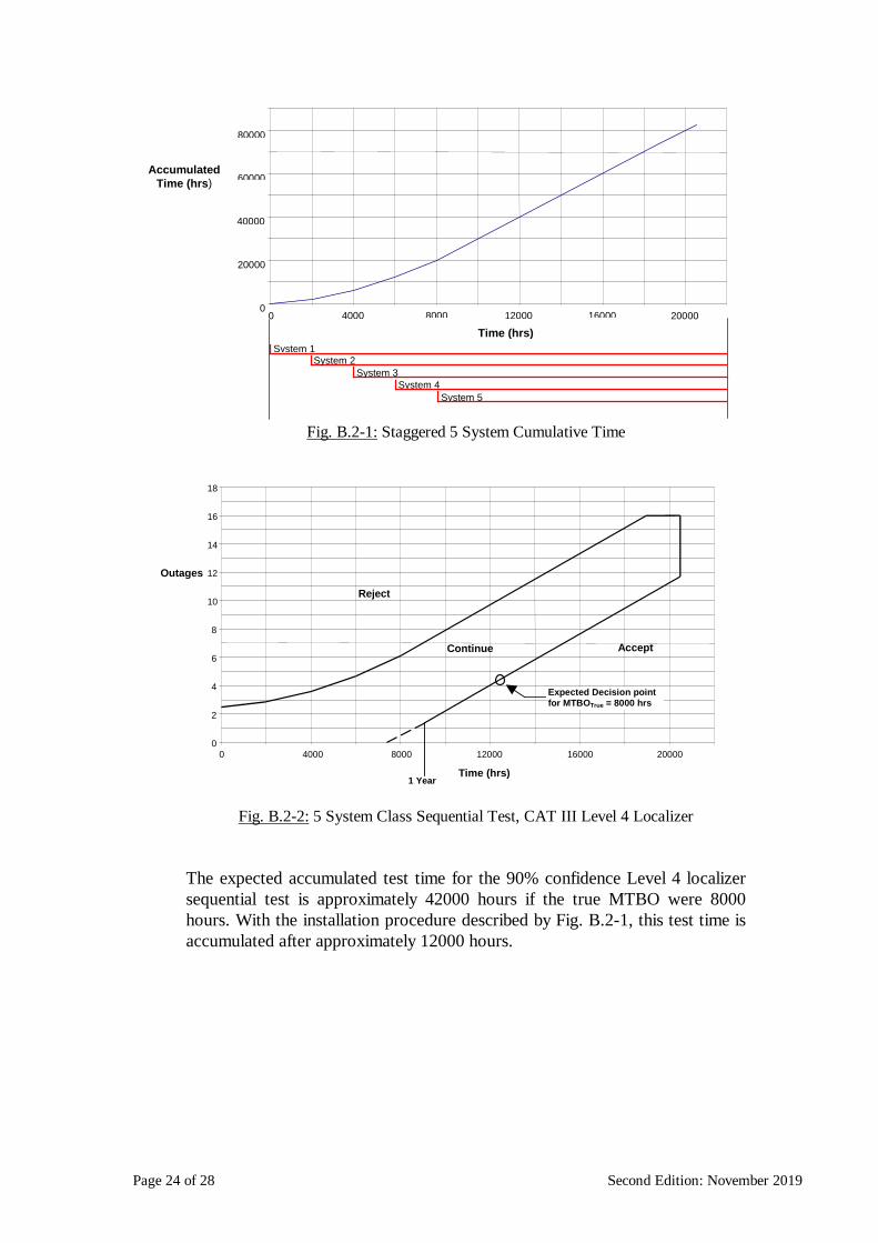
If multiple identical systems are to be installed, a single sequential test plan can be used to demonstrate the reliability of all systems. An example installation programme for 5 Level 4 Localizer systems and associated sequential test plan as a function of true (not accumulated) time are shown in Fig. B.2-1 and Fig. B.2-2 respectively.
Page 24 of 28 Second Edition: November 2019
0
20000
40000
60000
80000
0 4000 8000 12000 16000 20000
AccumulatedTime (hrs)
System 1System 2
System 3System 4
System 5
Time (hrs)
Fig. B.2-1: Staggered 5 System Cumulative Time
0
2
4
6
8
10
12
14
16
18
0 4000 8000 12000 16000 20000
Time (hrs)
Outages
AcceptContinue
Reject
Expected Decision pointfor MTBOTrue = 8000 hrs
1 Year
Fig. B.2-2: 5 System Class Sequential Test, CAT III Level 4 Localizer
The expected accumulated test time for the 90% confidence Level 4 localizer sequential test is approximately 42000 hours if the true MTBO were 8000 hours. With the installation procedure described by Fig. B.2-1, this test time is accumulated after approximately 12000 hours.
Page 25 of 28 Second Edition: November 2019
B.2.1 Outlier Detection
There is a risk that the reliability demonstration procedure may be contaminated by a ‘rogue’ outlier system. It is essential that such a rogue system be removed from the group of systems. But equally a system must not be removed from the group if the unusual performance of that system is merely a statistical rarity. A large variation in the observed MTBO of the same type of ILS system is to be expected due to the small number of outages. It is desirable to have a procedure available to remove a system from the group when the variation of that system from the group is significantly greater than would be expected. A mechanism to enable the removal of a system from a class is to use a test of discordancy. A sequential test of discordancy can be used to continuously examine whether a system’s performance is so different from the performance of the other systems that it can be justifiably removed from the Class. The test can be designed around the fact that if all systems possessed the same reliability, the arrangement of outages between systems would follow a multinomial distribution.

Page 26 of 28 Second Edition: November 2019
APPENDIX C - POST-CERTIFICATION RELIABILITY MONITORING
C.1 INTRODUCTION
Beyond initial certification it is necessary to continue to monitor the reliability of the installed systems. A suitable method to assess the behaviour of a particular installation is to keep the records and calculate the average MTBO over the last five to eight failures of the equipment. A decision rule could be such that if the point estimate dropped below the required MTBO value a downgrading is performed. However ICAO Annex 10 requires that the monitoring procedure should not result in frequent re-categorizations. It is recommended that target and alert levels should be set for the equipment reliability. A failure of the point estimate to meet the alert limit results in a re-classification of the system. Target MTBO values are proposed which, if met, should make re-categorization unlikely. If the point estimate falls below the target MTBO value then procedures may need to be reviewed to increase system reliability. For the purpose of comparison with the target value, point estimates may be obtained from more than one system and/or from more than 5-8 outages. Example target levels are set at an MTBO value, which if met would result in compliance with the requirement that designations should not be subject to frequent change.
Facility Performance
Category
Sub-system MTBO Target Hours
MTBO Alert Hours
III (Level 4) Localizer/Az 6000 4000 III (Level 3) Localizer/Az 3000 2000 III El/El 3000 2000 II Localizer/Az 3000 2000 II El/El 3000 2000 I, Level 2 Localizer/Az 1500 1000 I, Level 2 El/El 1500 1000
Table C.1-1: MTBO Reliability Target and Alert levels
It is recommended to monitor the reliability of individual and global populations of the different equipment types. This data to be calculated for current situation (including systematic faults and failures) and also for the historical data (where systematic faults, that have been cured, are excluded).

Page 27 of 28 Second Edition: November 2019
After identification of a fault the Engineering Authority and Design Authority shall consider whether it is a systematic or random fault. If it was considered as a random fault it shall be included in the MTBO calculations. Systematic faults as yet uncured shall also be included in the MTBO calculations.
C.1.1 Monitor Initialization
As it is likely that some systems will not have experienced five failures during certification, a solution is to initialize them with the observed MTBO obtained when the equipment is accepted (the total accumulated operating time divided by the total number of outages). The starting point estimate for an individual MTBO monitor can be represented by 5 equally spaced ‘virtual’ outages producing a point estimate corresponding to the observed MTBO. To accommodate the no-outage situation it is recommended that the maximum MTBO initialization level be set to twice the required MTBO.
Fig. C.1-1: Individual MTBO Monitoring Following Class Certification
For systems with a small number of operating hours (i.e. subsequent systems that have been certified via the fast-track class route) the monitoring process should be modified so as to be more sensitive to insufficient reliability. It is therefore recommended that the point estimate be initialized more conservatively, for example 1.25 times the required MTBO (θ1). The value of 1.25 is considered a reasonable value, between the MTBO requirement, expected system target and the higher value used in the definition of the sequential test plan. This initialization level allows one outage to occur shortly after certification without having to re-classify, however, two failures will result in a re-classification.

Page 28 of 28 Second Edition: November 2019
During the class certification period it is recommended to have regular (at least monthly) review of MTBO. The same periodic review period should be used for the monitoring process.
The decision procedure for monitoring initialization following certification is shown in Fig C.1-2.
No
Yes
MonitoringProcess
Start
IsCertificationTime < θ1?
No
Yes
Initialise Monitor FromObserved MTBO
[upto a maximum of2.0× θ1]
Initialise MonitorFrom 1.25 × θ1
Fig. C.1-2: Monitoring Technique Decision Rule
— END —