Embed Size (px)
Citation preview
TCDS No.: IM.A.196 Boeing 747 Page 1 of 51 Issue 10 29 June 2012
European Aviation Safety Agency
EASA
TYPE-CERTIFICATE
DATA SHEET
No. IM.A.196
for Boeing 747
Type Certificate Holder: The Boeing Company
P.O. Box 3707
Seattle, WA 98124-2207 USA
Airworthiness Category: Large Aeroplanes
Major Modification: 747-400BCF
For Models: 747-100 747-200B 747-300 747-400 747-8F 747-200C 747-400F 747-8 747-200F

TCDS No.: IM.A.196 Boeing 747 Page 2 of 51 Issue 10 29 June 2012
Intentionally left blank
TCDS No.: IM.A.196 Boeing 747 Page 3 of 51 Issue 10 29 June 2012
TABLE OF CONTENT
SECTION 1: GENERAL (ALL VARIANTS) 4
SECTION 2: 747-100, -200B, -200C, -200F, -300 VARIANT 5 I General II Certification Basis III Technical Characteristics and Operational Limitations IV Operating and Service Instructions V Notes
SECTION 3: 747-400 VARIANT 10 I General II Certification Basis III Technical Characteristics and Operational Limitations IV Operating and Service Instructions V Notes
SECTION 4: 747-400F VARIANT 16 I General II Certification Basis III Technical Characteristics and Operational Limitations IV Operating and Service Instructions V Notes
SECTION 5: 747-400 BCF Major Modification 21 I General II Certification Basis III Technical Characteristics and Operational Limitations IV Operating and Service Instructions V Notes
SECTION 6: 747-8F 24 I General II Certification Basis III Technical Characteristics and Operational Limitations IV Operating and Service Instructions V Notes
SECTION 7: (-8 VARIANT) 38 I General II Certification Basis III Technical Characteristics and Operational Limitations IV Operating and Service Instructions V Notes
SECTION 8: ADMINISTRATIVE 51 I Acronyms and Abbreviations II Type Certificate Holder Record III Change Record
TCDS No.: IM.A.196 Boeing 747 Page 4 of 51 Issue 10 29 June 2012
SECTION 1: GENERAL (ALL VARIANTS) 1. Data Sheet No: IM.A.196 2. Performance Category: A 3. Certifying Authority: Federal Aviation Administration (USA) (Address) Seattle Aircraft Certification Office, 1601 Lind Avenue S.W. Renton, WA 98055-4056 United States of America 4. Type Certificate Holder: The Boeing Company (Address) P.O. Box 3707 Seattle, WA 98124-2207 United States of America 5. NOTE: The 747-100, -200B, -200F, -200C and -300 series were not subject to a validation by JAA
prior to EASA, therefore they are accepted by EASA under the provisions of EU Regulation 1702/2003.
The 747-400 and -400F were validated in a cooperative effort by 4 (5) EU Nationalities. In 2003, the 747-400 and -400F models were the subject of a JAA “catch-up” validation; this TCDS provides both the information as agreed for the 4(5) Authorities validation, as the agreed “catch-up” information.
The 747SR, 747SP, 747-100B, 747-100B SUD and 747-400D series are not included in
this TCDS as none has been identified as being eligible under Regulation 1702/2003. 6. EASA Type Certificate Data Sheet for Noise: Refer to TCDSN.IM.A.196. Note some early variants of the B747-100, -200 and -300 are accepted by EASA on the
basis that they comply only with Chapter 2 of ICAO Annex 16, Volume I. Any such aircraft registered in the EU may not be operated within the EU.
7. FAA Type Certificate Data Sheet A20WE
TCDS No.: IM.A.196 Boeing 747 Page 5 of 51 Issue 10 29 June 2012
SECTION 2: 747-100, -200B, -200C, -200F, -300 VARIANT
I. General 1. Aircraft: Boeing 747 2. EASA Validation Date: 03 September 1970 (-100) 16 January 1971 (-200B) 03 March 1972 (-200F) 23 February 1987 (-200C) 22 February 1984 (-300) II. Certification Basis 1. FAA Certification Date: 30 December 1969 (-100) 23 December 1970 (-200B) 07 March 1972 (-200F) 17 April 1973 (-200C) 01 March 1983 (-300) 2. FAA Certification Basis:
Refer FAA Type Certificate Data Sheet No. A20WE 3. EASA Validation Basis:
CRI H-01 Instructions for Continued Airworthiness (ICA) on Electrical Wiring Interconnecting Systems (EWIS)
In accordance with Regulation (EC) 1702/2003:
Certification basis: FAA Certification Basis as listed in FAA Type Certification Data Sheet No. A20WE
Noise ICAO Annex 16, Volume I (Refer to TCDSN.IM.A.196 for details) Prevention of Intentional Fuel Venting ICAO Annex 16, Volume II, Part II, Chapter 2
Adopted FAA Special Conditions: Refer to FAA TCDS A20WE
Adopted FAA Exemptions Granted:
Refer to FAA TCDS A20WE
Adopted FAA Equivalent Safety Findings: Refer to FAA TCDS A20WE
TCDS No.: IM.A.196 Boeing 747 Page 6 of 51 Issue 10 29 June 2012
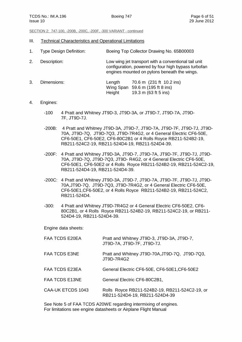
SECTION 2: 747-100, -200B, -200C, -200F, -300 VARIANT - continued
III. Technical Characteristics and Operational Limitations 1. Type Design Definition: Boeing Top Collector Drawing No. 65B00003 2. Description: Low wing jet transport with a conventional tail unit
configuration, powered by four high bypass turbofan engines mounted on pylons beneath the wings.
3. Dimensions: Length 70.6 m (231 ft 10.2 ins)
Wing Span 59.6 m (195 ft 8 ins) Height 19.3 m (63 ft 5 ins)
4. Engines:
-100 4 Pratt and Whitney JT9D-3, JT9D-3A, or JT9D-7, JT9D-7A, JT9D- 7F, JT9D-7J. -200B: 4 Pratt and Whitney JT9D-3A, JT9D-7, JT9D-7A, JT9D-7F, JT9D-7J, JT9D-
70A, JT9D-7Q, JT9D-7Q3, JT9D-7R4G2, or 4 General Electric CF6-50E, CF6-50E1, CF6-50E2, CF6-80C2B1 or 4 Rolls Royce RB211-524B2-19, RB211-524C2-19, RB211-524D4-19, RB211-524D4-39.
-200F: 4 Pratt and Whitney JT9D-3A, JT9D-7, JT9D-7A, JT9D-7F, JT9D-7J, JT9D-
70A, JT9D-7Q, JT9D-7Q3, JT9D- R4G2, or 4 General Electric CF6-50E, CF6-50E1, CF6-50E2 or 4 Rolls Royce RB211-524B2-19, RB211-524C2-19, RB211-524D4-19, RB211-524D4-39.
-200C: 4 Pratt and Whitney JT9D-3A, JT9D-7, JT9D-7A, JT9D-7F, JT9D-7J, JT9D-
70A,JT9D-7Q, JT9D-7Q3, JT9D-7R4G2, or 4 General Electric CF6-50E, CF6-50E1,CF6-50E2, or 4 Rolls Royce RB211-524B2-19, RB211-524C2, RB211-524D4.
-300: 4 Pratt and Whitney JT9D-7R4G2 or 4 General Electric CF6-50E2, CF6-
80C2B1, or 4 Rolls Royce RB211-524B2-19, RB211-524C2-19, or RB211-524D4-19, RB211-524D4-39.
Engine data sheets: FAA TCDS E20EA Pratt and Whitney JT9D-3, JT9D-3A, JT9D-7,
JT9D-7A, JT9D-7F, JT9D-7J.
FAA TCDS E3NE Pratt and Whitney JT9D-70A,JT9D-7Q, JT9D-7Q3, JT9D-7R4G2
FAA TCDS E23EA General Electric CF6-50E, CF6-50E1,CF6-50E2 FAA TCDS E13NE General Electric CF6-80C2B1, CAA-UK ETCDS 1043 Rolls Royce RB211-524B2-19, RB211-524C2-19, or
RB211-524D4-19, RB211-524D4-39
See Note 5 of FAA TCDS A20WE regarding intermixing of engines. For limitations see engine datasheets or Airplane Flight Manual
TCDS No.: IM.A.196 Boeing 747 Page 7 of 51 Issue 10 29 June 2012
SECTION 2: 747-100, -200B, -200C, -200F, -300 VARIANT - continued
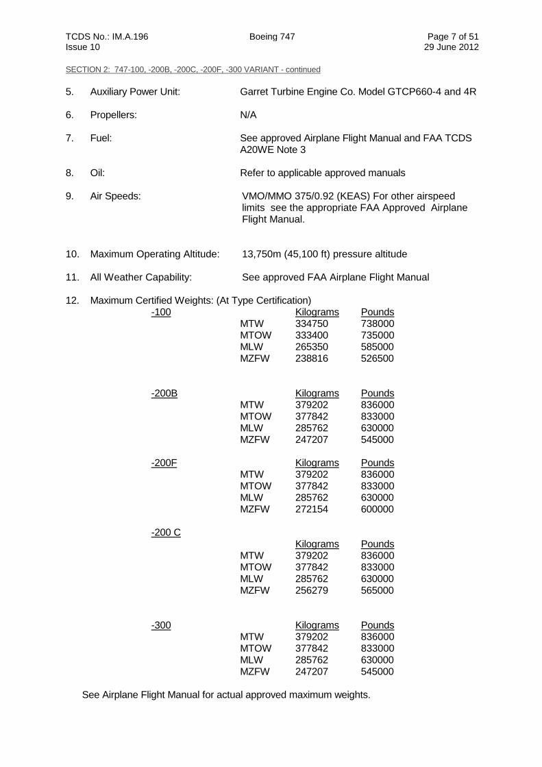
5. Auxiliary Power Unit: Garret Turbine Engine Co. Model GTCP660-4 and 4R 6. Propellers: N/A 7. Fuel: See approved Airplane Flight Manual and FAA TCDS A20WE Note 3 8. Oil: Refer to applicable approved manuals 9. Air Speeds: VMO/MMO 375/0.92 (KEAS) For other airspeed
limits see the appropriate FAA Approved Airplane Flight Manual.
10. Maximum Operating Altitude: 13,750m (45,100 ft) pressure altitude 11. All Weather Capability: See approved FAA Airplane Flight Manual
12. Maximum Certified Weights: (At Type Certification) -100 Kilograms Pounds MTW 334750 738000 MTOW 333400 735000 MLW 265350 585000
MZFW 238816 526500
-200B Kilograms Pounds MTW 379202 836000 MTOW 377842 833000 MLW 285762 630000
MZFW 247207 545000 -200F Kilograms Pounds MTW 379202 836000 MTOW 377842 833000 MLW 285762 630000
MZFW 272154 600000 -200 C Kilograms Pounds MTW 379202 836000 MTOW 377842 833000 MLW 285762 630000
MZFW 256279 565000
-300 Kilograms Pounds MTW 379202 836000 MTOW 377842 833000 MLW 285762 630000
MZFW 247207 545000
See Airplane Flight Manual for actual approved maximum weights.
TCDS No.: IM.A.196 Boeing 747 Page 8 of 51 Issue 10 29 June 2012
SECTION 2: 747-100, -200B, -200C, -200F, -300 VARIANT - continued
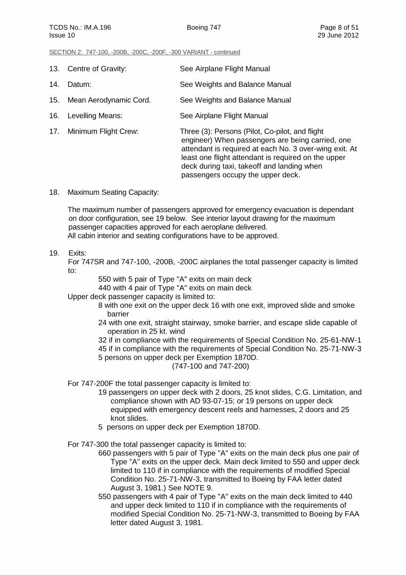
13. Centre of Gravity: See Airplane Flight Manual
14. Datum: See Weights and Balance Manual
15. Mean Aerodynamic Cord. See Weights and Balance Manual
16. Levelling Means: See Airplane Flight Manual
17. Minimum Flight Crew: Three (3): Persons (Pilot, Co-pilot, and flight engineer) When passengers are being carried, one
attendant is required at each No. 3 over-wing exit. At least one flight attendant is required on the upper deck during taxi, takeoff and landing when passengers occupy the upper deck.
18. Maximum Seating Capacity:
The maximum number of passengers approved for emergency evacuation is dependant on door configuration, see 19 below. See interior layout drawing for the maximum passenger capacities approved for each aeroplane delivered. All cabin interior and seating configurations have to be approved.
19. Exits:
For 747SR and 747-100, -200B, -200C airplanes the total passenger capacity is limited to:
550 with 5 pair of Type "A" exits on main deck 440 with 4 pair of Type "A" exits on main deck
Upper deck passenger capacity is limited to: 8 with one exit on the upper deck 16 with one exit, improved slide and smoke
barrier 24 with one exit, straight stairway, smoke barrier, and escape slide capable of
operation in 25 kt. wind 32 if in compliance with the requirements of Special Condition No. 25-61-NW-1 45 if in compliance with the requirements of Special Condition No. 25-71-NW-3 5 persons on upper deck per Exemption 1870D.
(747-100 and 747-200) For 747-200F the total passenger capacity is limited to:
19 passengers on upper deck with 2 doors, 25 knot slides, C.G. Limitation, and compliance shown with AD 93-07-15; or 19 persons on upper deck equipped with emergency descent reels and harnesses, 2 doors and 25 knot slides.
5 persons on upper deck per Exemption 1870D. For 747-300 the total passenger capacity is limited to:
660 passengers with 5 pair of Type "A" exits on the main deck plus one pair of Type "A" exits on the upper deck. Main deck limited to 550 and upper deck limited to 110 if in compliance with the requirements of modified Special Condition No. 25-71-NW-3, transmitted to Boeing by FAA letter dated August 3, 1981.) See NOTE 9.
550 passengers with 4 pair of Type "A" exits on the main deck limited to 440 and upper deck limited to 110 if in compliance with the requirements of modified Special Condition No. 25-71-NW-3, transmitted to Boeing by FAA letter dated August 3, 1981.
TCDS No.: IM.A.196 Boeing 747 Page 9 of 51 Issue 10 29 June 2012
SECTION 2: 747-100, -200B, -200C, -200F, -300 VARIANT - continued
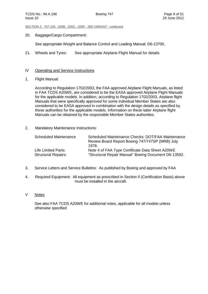
20. Baggage/Cargo Compartment: See appropriate Weight and Balance Control and Loading Manual: D6-13700. 21. Wheels and Tyres: See appropriate Airplane Flight Manual for details
IV Operating and Service Instructions
1. Flight Manual:
According to Regulation 1702/2003, the FAA approved Airplane Flight Manuals, as listed in FAA TCDS A20WE, are considered to be the EASA approved Airplane Flight Manuals for the applicable models. In addition, according to Regulation 1702/2003, Airplane flight Manuals that were specifically approved for some individual Member States are also considered to be EASA approved in combination with the design details as specified by these authorities for the applicable models. Information on these latter Airplane flight Manuals can be obtained by the responsible Member States authorities.
2. Mandatory Maintenance Instructions:
Scheduled Maintenance Scheduled Maintenance Checks: DOT/FAA Maintenance Review Board Report Boeing 747/747SP (MRB) July 1978.
Life Limited Parts: Note 4 of FAA Type Certificate Data Sheet A20WE Structural Repairs: “Structural Repair Manual" Boeing Document D6-13592.
3. Service Letters and Service Bulletins: As published by Boeing and approved by FAA 4. Required Equipment: All equipment as prescribed in Section II (Certification Basis) above
must be installed in the aircraft. V Notes
See also FAA TCDS A20WE for additional notes, applicable for all models unless otherwise specified
TCDS No.: IM.A.196 Boeing 747 Page 10 of 51 Issue 10 29 June 2012
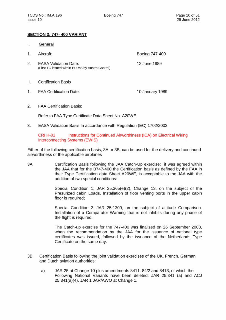
SECTION 3: 747- 400 VARIANT I. General 1. Aircraft: Boeing 747-400 2. EASA Validation Date: 12 June 1989 (First TC issued within EU MS by Austro Control)
II. Certification Basis 1. FAA Certification Date: 10 January 1989 2. FAA Certification Basis:
Refer to FAA Type Certificate Data Sheet No. A20WE 3. EASA Validation Basis In accordance with Regulation (EC) 1702/2003
CRI H-01 Instructions for Continued Airworthiness (ICA) on Electrical Wiring Interconnecting Systems (EWIS)
Either of the following certification basis, 3A or 3B, can be used for the delivery and continued airworthiness of the applicable airplanes 3A Certification Basis following the JAA Catch-Up exercise: it was agreed within
the JAA that for the B747-400 the Certification basis as defined by the FAA in their Type Certification data Sheet A20WE, is acceptable to the JAA with the addition of two special conditions:
Special Condition 1; JAR 25.365(e)(2), Change 13, on the subject of the Presurized cabin Loads. Installation of floor venting ports in the upper cabin floor is required; Special Condition 2: JAR 25.1309, on the subject of attitude Comparison. Installation of a Comparator Warning that is not inhibits during any phase of the flight is required. The Catch-up exercise for the 747-400 was finalized on 26 September 2003, when the recommendation by the JAA for the issuance of national type certificates was issued, followed by the issuance of the Netherlands Type Certificate on the same day.
3B Certification Basis following the joint validation exercises of the UK, French, German
and Dutch aviation authorities:
a) JAR 25 at Change 10 plus amendments 8411. 84/2 and 8413, of which the Following National Variants have been deleted: JAR 25.341 (a) and ACJ 25.341(a)(4). JAR 1 JAR/AWO at Change 1.
TCDS No.: IM.A.196 Boeing 747 Page 11 of 51 Issue 10 29 June 2012
SECTION 3: 747- 400 VARIANT - continued
Plus for the purposes of deleting National Variants and thus harmonizing requirements to a maximum extent, the following paragraphs of specified later JAR 25 amendments.
(a) Amendment 87/2: JAR 25.107 (d) JAR (BB) 25.107 (d) JAR 25 X 519 (a) JAR 25.735 (f) (1) and (h) (1) JAR 25.1303 (b) (4) and (c) (1) JAR 25 X 1328 JAR 25.1333 (b) JAR 25.1459 (b)
(b) JAR 25 Change 12: JAR 25.341 (a)
(c) Notices of Proposed Amendment: NPA 258, G -1 94 to JAR 25 NPA 25C-211 (Improved Seat Safety Standards)
b) Plus, for the purposes of reflecting current thinking JAR 25 Change 12: JAR 25.149 (e)
c) Excepting the following paragraphs of JAR 25 where, for features Unchanged in design and usage with respect to earlier variants and having a satisfactory service record, compliance with the stated Requirements have been accepted instead: JAR 25.107 (a) Replaced by FAR 25.107 (a) at amendment 41. JAR 25.109 (a) Replaced by FAR 25.109 (a) at amendment 41. JAR 25.149 (e) Replaced by FAR 25.149 (el at amendment 41. JAR 25.345 (g) Not applicable JAR 25.479 (c) (4) and JAR 25.483 Replaced by FAA Special Condition A-4. JAR 25.499 (e) Replaced by FAR 25.499 (e) at amendment 59. JAR 25.561 (b) (3) With respect to the interface loads at the airplane
side of the seats and commercial equipment installed in the passenger cabin. compliance to the following requirement has been accepted: All combinations up to a maximum of 8g at the following conditions: 4.5g downwards 2.0g upwards 8.0g forwards 1.5g rearwards 2.25g sidewards
JAR 25.571 (a) On the basis of compliance with FAR 25.571 through (d) amendment 9 and acceptance of the initial maintenance program and sublet3 to the introduction of an acceptable structural inspection program by January 1. 1994 full compliance with JAR 25.57 l(a) through (d) may be waived until January 1. 1994.
TCDS No.: IM.A.196 Boeing 747 Page 12 of 51 Issue 10 29 June 2012
SECTION 3: 747- 400 VARIANT - continued
JAR 25.675 Replaced by BCAR Section D for UK certification and by FAR 25.675 amendment 37 for CAA-NL, DGAC and LBA.
JAR 25.683 (b) Not applicable to unchanged parts of and (c) control systems. JAR 25.729(f) Replaced by FAR 25.729(f) at amendment 59. JAR 25.772 Replaced by FAR 25.772 amendment 46. JAR 25.785 (i) As for JAR 25.561 (b) (3) JAR 25.787 (a) With respect to the open closets located on the
upper deck (normally at Station no. 956) and just aft of door 5 (normally at Station no. 2300), replaced by FAR 25.787 (a) at amendment 31.
JAR 25.812 (g) (1) Replaced by FAR 25.812 (g) at amendment 31. JAR 25.903 (dl (1) With respect to the provision of separate
powersupplies to the engine shut-off valve close coils, replaced by FAR 25.903 (d) (1) at amendment 31.
JAR 25.1309 Not applicable to parts of a/c that are unchanged in both design and usage from earlier models and that have shown satisfactory service experience.
JAR 25.1435 (a) (1) Replace by BCAR Section D, Chapter 06-2; 6 for UK certification and FAR 25.1435 (a)(l) at amendment 59 for CAA-NL, DCAC and L8A.
Note: references to FAR 25 imply the FAA interpretations of FAR 25.
Exemptions have been granted against compliance with the following paragraphs of JAR 25: JAR 25.671 (c) (3) JAR 25.561 (d) with respect to the wing fuel tanks JAR 25.1529 based upon manual system that meets the intent of FAR 25.1529 at Amendment 21 and the data presentation and accuracy equivalent safety to FAR 25.1629 at Amendment 21
d) Equivalent safety findings against the following requirements based on Boeing applications: Due to the use of Vs1g as the basis for Reference Speeds: JAR 25.21 (c), 103, 107, 119, 121, 125, 145, 147, 149, 161, 175, 177, 201, 207, 233, 237. JAR 25.101(c) See Joint Evaluation summary Part 4 JAR 25.X 132 See Joint Evaluation summary Part 4 JAR 25.X.745 See Joint Evaluation summary Item 3.4(10) JAR25.783(e) See Boeing Letter B-221T-89-2569 JAR 25.785(c) See Joint Evaluation summary Part 4 JAR 25.809(f)(1)(iii) See Boeing Letter B-221T-89-1744 E.S. item 3.21(6) JAR25.863(a) See Boeing Letter B-221T-89-1541 JAR 25.1303(c)(1)) See Joint Evaluation summary Part 4 JAR25.1389(b)(3) See Boeing Letter B-221T-89-639 JAR 25.1435(a)(2) See Joint Evaluation summary Part 4 JAR25.1438 See Boeing Letter B-221T-89-1493 JAR25.1447(c)(3) See Boeing Letter B-221T-89-991
TCDS No.: IM.A.196 Boeing 747 Page 13 of 51 Issue 10 29 June 2012
SECTION 3: 747- 400 VARIANT - continued
JAR25.1453(a) See Boeing Letter B-221T-89-0694 JAR 25.101(c) See Joint Evaluation summary Part 4 JAR25.A1103(b)(2) See Boeing Letter B-221T-89-1019 JAR25.A1193(e)(3) See Boeing Letter B-221T-89-1254
Noise ICAO Annex 16, Volume I, Chapter 3 (Refer to TCDSN.IM.A.196 for details) Prevention of Intentional Fuel Venting ICAO Annex 16, Volume II, Part II, Chapter 2
III. Technical Characteristics and Operational Limitations 1. Design Standard: Design Standards identified as the basis for this Type
Certificate is that of the Series Design defined by Top Drawing No. 65 B00002 747 Final Assembly
2. Description: Low wing jet transport with a conventional tail unit configuration, powered by four high bypass turbofan engines mounted on pylons beneath the wings.
3. Dimensions: Length 70.6 m (231 ft 10.2 in)
Span 64.44 m (211 ft 5 in) Height 19.4 m (63 ft 8 in)
4. Engines: 4 Pratt and Whitney PW4056, General Electric CF6-
80C2B1F, CF6-80C2B5F; or Rolls Royce RB211-524G2-19, RB211-524G3-19, RB211-524H2-19, RB211-524G2-T-19, RB211-524G3-T-19, RB211-524H2-T-19.
Engine data sheets:
FAA TCDS E24NE Pratt and Whitney 4056 FAA TCDS E13NE General Electric CF6-80C2B1F, CF6-80C2B5F, CAA-UK ETCDS 1046 Rolls Royce RB211-524G2-19, RB211-524G3-19,
RB211-524G2-T-19, RB211-524G3-T-19,
CAA-UK ETCDS 1048 Rolls Royce RB211-524H2-19, RB211-524H2-T-19
WARNING: To prevent unsafe airplane handling characteristics, PW4000 series engines with electronic engine control (EEC) part number 791100-14-102 (Pratt & Whitney part number 54D043) must not be installed on the same airplane as PW4000 series engines that have the ring case compressor configuration. This combination of engine configurations is not approved because of a significant difference in engine acceleration rates and the effect of that difference on airplane handling characteristics. Ring case compressor equipped engines were approved with the same engine model number as previously approved PW4000 configurations, and must be identified by the presence of a “/A5” marked at the end of the “INSTL ARR” block on the engine data plate.
See FAA TCDS A20WE NOTE 5 for further information regarding intermixing engines
TCDS No.: IM.A.196 Boeing 747 Page 14 of 51 Issue 10 29 June 2012
SECTION 3: 747- 400 VARIANT - continued
5. Auxiliary Power Unit: Pratt and Whitney of Canada Type PW901A 6. Propellers: N/A 7. Fuel: See approved Airplane Flight Manual and
FAA TCDS A20WE Note 3 8. Oil: Refer to applicable approved manuals 9. Air Speeds: VMO/MMO 375/0.92 (KCAS) For other airspeed limits see the appropriate FAA Approved Airplane
Flight Manual 10. Maximum Operating Altitude: 13,750m (45,100 ft) pressure altitude 11. All Weather Capability: See approve Airplane flight Manual 12. Maximum Certified Weights: (At Type Certification) See approved
Airplane Flight Manual for the appropriate weights.
Pounds Kilograms MTW 877.000 397,800 MTOW 875.000 396.893 MLW 630,000 285.762 MZFW 544,000 246.754 13. Centre of Gravity: See Airplane Flight Manual 14. Datum: See Weights and Balance Manual 15. Mean Aerodynamic Cord (MAC): See Weights and Balance Manual 16. Levelling Means: See Airplane Flight Manual 17. Minimum Flight Crew: Two (2): Persons (Pilot and Co-pilot)
When passengers are being carried, one attendant is required at each No. 3 over-wing exit. At least one flight attendant is required on the upper deck during taxi, takeoff and landing when passengers occupy the upper deck.
18. Maximum Seating Capacity:
The maximum number of passengers approved for emergency evacuation is dependant on door configuration, see 19 below. See interior layout drawing for the maximum passenger capacities approved for each aeroplane delivered. All cabin interior and seating configurations have to be approved.
19. Exits:
660 passengers with 5 pair of Type "A" exits on main deck plus one pair of Type "A" exits on the upper deck. (Main deck limited to 550 and upper deck limited to 110 if in compliance with the requirements of modified Special Condition Number 25-71-NW-3,
TCDS No.: IM.A.196 Boeing 747 Page 15 of 51 Issue 10 29 June 2012
SECTION 3: 747- 400 VARIANT - continued
transmitted to Boeing by FAA letter dated August 3, 1981.) See FAA TCDS A20WE NOTE 9.
20. Baggage/Cargo Compartment: See the appropriate FAA approved Weight and Balance Control manual ( D043U400). 21. Wheels and Tyres: See approved FAA Airplane flight Manual for details. IV. Operating and Servicing Instructions 1. Flight Manual: FAA Approved flight Manuals: D6-U10001, D6-U10002 and D6-U10003. For airplanes delivered according the JAA Certification Basis (3 A), JAA approved
supplements are applicable. 2. Mandatory Maintenance Instructions:
Scheduled Maintenance Checks as for Boeing MRB Report Boeing Maintenance Manual
Doc. D633U101-05 and D633U101-54
Life Limited Parts and required inspection intervals are listed in the FAA approved Airworthiness Limitations Section of the Boeing Maintenance Planning Data Document D621U400.
Structural Repair Manual – Boeing Document D634U102
3. Service Letters and Service Bulletins: As published by Boeing and approved by FAA. 4. Required Equipment: All equipment as prescribed in Section II (Certification Basis)
above must be installed in the aircraft. V Notes
See also FAA TCDS A20WE for additional notes, applicable for all models unless otherwise specified
TCDS No.: IM.A.196 Boeing 747 Page 16 of 51 Issue 10 29 June 2012
SECTION 4: 747- 400F VARIANT I. General 1. Aircraft: Boeing 747-400F 2. EASA Validation Date: 01 November 1993 (First TC issued within EU by CAA-NL)
II. Certification Basis 1. FAA Certification Date: 14 October 1993 FAA Type Certificate Data Sheet No. A20WE 2. FAA Certification Basis: See FAA TCDS A20WE 3. EASA Validation Basis In accordance with Regulation (EC) 1702/2003
CRI H-01 Instructions for Continued Airworthiness (ICA) on Electrical Wiring Interconnecting Systems (EWIS)
Either of the following certification basis, 3A or 3B, can be used for the delivery and continued airworthiness of the applicable airplanes 3A Certification Basis following the JAA Catch-Up exercise: it was agreed within
the JAA that for the B747-400F the Certification basis as defined by the FAA in their Type Certification data Sheet A20WE, is acceptable to the JAA with the addition of two special conditions:
Special Condition 1; JAR 25.365(e)(2), Change 13, on the subject of the Presurized cabin Loads. Installation of floor venting ports in the upper cabin floor is required; Special Condition 2: JAR 25.1309, on the subject of attitude Comparison. Installation of a Comparator Warning that is not inhibits during any phase of the flight is required. The Catch-up exercise for the 747-400F was finalized on 26 September 2003, when the recommendation by the JAA for the issuance of national type certificates was issued, followed by the issuance of the Netherlands Type Certificate on the same day.
3B Certification Basis following the joint validation exercise of the UK, French, German and Dutch aviation authorities:
The reference certification basis for the 8747-400 series (See "Boeing 747-400 Joint Certification Basis and Additional Requirements for certification in Germany, France, United Kingdom and the Netherlands" issue 2 of April 14. 1992), plus
For the components or areas affected by the change: JAR 25, Change 12 and Amendment 88/1.
TCDS No.: IM.A.196 Boeing 747 Page 17 of 51 Issue 10 29 June 2012
SECTION 4: 747- 400F VARIANT - continued
Note
Exceptions listed in the 747-400 series Joint Certification basis apply to the 747-400F, except for the following two which are modified as follows: JAR 25.365 Boeing has committed to comply with the intent of FAR 25.365, Amendment 25-54 by assuring continued safe flight and landing with a 20 square foot hole in the main deck cargo compartment or lower lobe cargo compartment or upper deck (exclusive of flight deck). Boeing will provide protection for systems critical for continued safe flight and landing and allow miscellaneous structure to fail as long as these failures do not affect flight safety. These miscellaneous structure components are main deck floor in Section 46, partitions and lavatory walls. This is the compliance method for JAR 25.365 used for the 747-400 series airplane and will also be used for the 747-400F (Reference. FAA 747-400F Certification Basis issue Paper G-1, Stage 5 and CRI C-5, stage 3). JAR 25.571(a) through (d): On the basis of compliance with FAR 25.571, Amendment 9, and acceptance of the initial maintenance program and subject to the introduction of an acceptable structural inspection program by January I , 1999 full compliance with JAR 25.571 (a) through (d) may be waived until January 1. 1999. (Ref. CRI C-3. stage 3).
b) Special Conditions related to novel or unusual design features or
unconventional usage (ref. draft JAR 21 .I6 (a) (1) and (2)). None identified c) Special conditions related to general experience (ref. Draft JAR 21.16(a)(3)) CRI D-4 Cargo and Service Doors CRI F-7 Lightning protection, indirect effects CRI F-8 HIRF d) Exemptions (ref. Draft JAR 21.17(a)(1)(i)) CRI F-1 Crew Slide JAR 25.809(f)(1)(v) CRI F04 Fireworthiness requirements for JAR 25.855(a)(1)(i) Ceiling and sidewall panels in the Lower lobe cargo compartments CRI F-5 Maindeck Cargo Compartment Firedetection response time JAR 25.858 CRI F-10 Upper Deck occupancy JAR 25.807, 25.809, 25.813 CRI F-12 Floor proximity escape path Marking JAR 25.812(e)
e) AA Airworthiness Standards for which Boeing elected to comply (ref. Draft JAR
21.17 (a)(1)(ii) and JAR 21.17 (e)) 5.1 The later effective amendments to JAR that Boeing has
chosen to comply with : JAR 25 Change 13, except NPA 25C, D-211
5.2 AA approved NPAs NPA 25B,D,G-244 Accelerate-Stop Distance
TCDS No.: IM.A.196 Boeing 747 Page 18 of 51 Issue 10 29 June 2012
SECTION 4: 747- 400F VARIANT - continued
f) Equivalent Safety Findings CRI D-1 Nose Cargo door Locking JAR 25.783 CRI F-11 Oxygen Dispensing Units JAR 25.1447(c)(3) Note 1: For the purpose of showing compliance to this type certification basis, Compliance must be demonstrated with the FAA certification basis (see FAA IP G-1, stage 5) and the Additional Technical conditions of the AA as defined in CRI A-8. Note 2:
Some AA countries have issued Additional National requirements to be complied with for the issue of a Type Certificate. These requirements are laid down in: CRI A-2 Additional National Design standards for type certification CRI A-3 National Environmental Standards
III. Technical Characteristics and Operational Limitations 1. Design Standard: Design Standards identified as the basis for this Type Certificate is that of the Series Design defined by Top Drawing No. 65 B00002 747 Final Assembly 2. Description: Low wing jet transport with a conventional tail unit
configuration, powered by four high bypass turbofan engines mounted on pylons beneath the wings.
3. Dimensions: Length 70.66 m (231 ft 10 in)
Span 64.44 m (211 ft 5 in) Height 19.33 m (63 ft 5 in)
4. Engines: 4 Pratt and Whitney PW4056, General Electric CF6-
80C2B1F, CF6-80C2B5F; or Rolls Royce RB211-524G2-19, RB211-524G3-19, RB211-524H2-19, RB211-524G2-T-19, RB211-524G3-T-19, RB211-524H2-T-19.
Engine data sheets:
FAA TCDS E24NE Pratt and Whitney 4056 FAA TCDS E13NE General Electric CF6-80C2B1F, CF6-80C2B5F, CAA-UK ETCDS 1046 Rolls Royce RB211-524G2-19, RB211-524G3-19,
RB211-524G2-T-19, RB211-524G3-T-19,
CAA-UK ETCDS 1048 Rolls Royce RB211-524H2-19, RB211-524H2-T-19
TCDS No.: IM.A.196 Boeing 747 Page 19 of 51 Issue 10 29 June 2012
SECTION 4: 747- 400F VARIANT - continued
WARNING: To prevent unsafe airplane handling characteristics, PW4000 series engines with electronic engine control (EEC) part number 791100-14-102 (Pratt & Whitney part number 54D043) must not be installed on the same airplane as PW4000 series engines that have the ring case compressor configuration. This combination of engine configurations is not approved because of a significant difference in engine acceleration rates and the effect of that difference on airplane handling characteristics. Ring case compressor equipped engines were approved with the same engine model number as previously approved PW4000 configurations, and must be identified by the presence of a “/A5” marked at the end of the “INSTL ARR” block on the engine data plate.
See FAA TCDS A20WE NOTE 5 for further information regarding intermixing engines
5. Auxiliary Power Unit: Pratt and Whitney of Canada Type PW801A
6. Propellers: N/A
7. Fuel: See approved Airplane Flight Manual and FAA TCDS A20WE Note 3 8. Oil: Refer to applicable approved manuals 9. Air Speeds: VMO/MMO 375/0.92 (KCAS) For other airspeed limits see the appropriate FAA Approved Airplane
Flight Manual 10. Maximum Operating Altitude: 13,750m (45,100 ft) pressure altitude 11. All Weather Capability: See approve Airplane flight Manual 12. Maximum Certified Weights: (At Type Certification) See approved
Airplane Flight Manual for the appropriate weights.
Pounds Kilograms MTW 877.000 397.800 MTOW 875.000 396.894 MLW 666,000 302.092 MZFW 635.000 288.030 13. Centre of Gravity: See Airplane Flight Manual 14. Datum: See Weights and Balance Manual 15. Mean Aerodynamic Cord (MAC): See Weights and Balance Manual 16. Levelling Means: See Airplane Flight Manual 17. Minimum Flight Crew: Two (2): Persons (Pilot and Co-pilot) 18. Maximum Seating Capacity:
For 747-400F airplanes the total persons capacity is limited to: Six (6) persons on the upper deck per FAA Exemption 1870E.
TCDS No.: IM.A.196 Boeing 747 Page 20 of 51 Issue 10 29 June 2012
SECTION 4: 747- 400F VARIANT - continued
19. Baggage/Cargo Compartment: See the appropriate FAA approved Weight and Balace Control manual (D043U550) 20. Wheels and Tyres: See approved FAA Airplane flight Manual for details. IV. Operating and Servicing Instructions 1. Flight Manual: FAA Approved flight Manuals : D6-U10001, D6-U10002 and D6-U10003. For airplanes delivered according the JAA Certification Basis (A), JAA approved
supplements are applicable. 2. Mandatory Maintenance Instructions:
Scheduled Maintenance Checks as for Boeing MRB Report Boeing Maintenance Manual
Doc. D633U101-05 and D633U101-54 Life Limited Parts and required inspection intervals are listed in the FAA approved
Airworthiness Limitations Section of the Boeing Maintenance Planning Data Document D621U400.
Structural Repair Manual – Boeing Document D634U102
3. Service Letters and Service Bulletins: As published by Boeing and approved by FAA. 4. Required Equipment: All equipment as prescribed in Section II (Certification Basis) above
must be installed in the aircraft.
TCDS No.: IM.A.196 Boeing 747 Page 21 of 51 Issue 10 29 June 2012
SECTION 5: 747-400 BCF (Major Modification) I. General 1. Aeroplane: Boeing 747-400 BCF
(Boeing Converted Freighter) 2. Reference Application Date for EASA Validation: 09 September 2005 3. FAA Certification Date: 13 December 2005
4. EASA Validation Date: 03 May 2007 II. Certification Basis 1. TCDS of Certifying Authority: Number: A20WE Issued by: FAA 3. EASA Validation Basis:
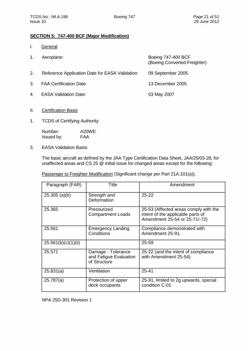
The basic aircraft as defined by the JAA Type Certification Data Sheet, JAA/25/03-28, for unaffected areas and CS 25 @ initial issue for changed areas except for the following: Passenger to Freighter Modification (Significant change per Part 21A.101(a)).
Paragraph (FAR) Title Amendment
25.305 (a)(b) Strength and Deformation
25-22
25.365 Pressurized Compartment Loads
25-53 (Affected areas comply with the intent of the applicable parts of Amendment 25-54 or 25-71/-72)
25.561 Emergency Landing Conditions
Compliance demonstrated with Amendment 25-91.
25.561(b)(c)(1)(ii) 25-59
25.571 Damage - Tolerance and Fatigue Evaluation of Structure
25-22 (and the intent of compliance with Amendment 25-54)
25.831(a) Ventilation 25-41
25.787(a) Protection of upper deck occupants
25-91, limited to 2g upwards, special condition C-01
NPA 25D-301 Revision 1
TCDS No.: IM.A.196 Boeing 747 Page 22 of 51 Issue 10 29 June 2012
SECTION 5: 747-400 BCF (Major Modification) - continued
Upper Deck Interior Reconfiguration (Non-Significant change per Part 21A.101(a))
The validation basis for the changed aspects associated with the upper deck interior configuration rearrangement is unchanged from the 747-400 Series in accordance with Part 21A.101(b)(1).
The details of the Certification basis are documented in CRI A-01 for the B747-400BCF 4. Special Condition:
CRI D-02 Carriage of Couriers without complying with specified passenger-carrying requirements
CRI H-01 Instructions for Continued Airworthiness (ICA) on Electrical Wiring
Interconnecting Systems (EWIS) 5. Means of Compliance:
CRI D-01 Requirements for fuselage doors (NPA 25D-301 revision 1) 6. Reversion request: CRI C-01 Crash loads 2G upwards for Emergency Landing Condition
III. Technical Characteristics and Operational Limitations
1. Major Change Design Definition:
Boeing Service Bulletin 747-00-2004
2. Maximum Certified Weights:
Maximum Taxi Weight 873.000 lbs. (395,986 kg) Maximum Take-off Weight 870.000 lbs. (394.625 kg) Maximum Landing Weight 652.000 lbs. (295.742 kg) Maximum Zero Fuel Weight 610.000 lbs. (276.691 kg)
3. Operating Limitations
Refer to approved Airplane Flight Manual.
4. Maximum number of Passengers
There are no provisions for the carriage of passengers. A maximum of 19 couriers can occupy the aft cabin of the upper deck as defined in AFM.
5. Other relevant information
Relevant information not included in this Type Certificate Data Sheet may be found in the FAA Type Certificate Data Sheet No A20WE.
TCDS No.: IM.A.196 Boeing 747 Page 23 of 51 Issue 10 29 June 2012
SECTION 5: 747-400 BCF (Major Modification) - continued
IV Operating and Service Instructions 1. Flight Manual Supplement
FAA approved Flight Manual Boeing Document: D6U10001/2/3 depending on installed
engines, with Supplement FAA approved Weight and Balance Manual: Boeing Document D043-U544
2. Mandatory Maintenance Instructions
High Cycle Maintenance Planning Data (MPD) Document D621U400. 3 Service Bulletins and Airworthiness Directives
A 747-400 SF (Special Freighter), or optionally known as a 747-400 BCF (Boeing Converted Freighter), is a 747-400 Series passenger airplane that has been modified in accordance with FAA-approved Boeing Service Bulletin 747-00-2004 to operate in a freighter configuration. These aircraft remain as 747-400 Series aircraft for documentation purposes on this TCDS and with regard to the applicability of airworthiness directives.
V Notes 1. Special Conditions, exemptions and Equivalent Safety Findings:
Special conditions, Exemptions and Equivalent Safety Findings that are part of the certification basis for the 747-400 Series apply to the airplane operating in the 747-400 SF configuration, unless otherwise noted in FAA Type Certificate data sheet A20WE.
TCDS No.: IM.A.196 Boeing 747 Page 24 of 51 Issue 10 29 June 2012
SECTION 6: 747-8F I. General 1. Aircraft Boeing 747-8F
2. Models Boeing 747-8F
3. EASA Validation Application Date 05 March 2007 (Reference date for EASA validation)
4. EASA Validation Date 19 August 2011 II. Certification Basis 1. Reference Application Date for FAA Certification: 31 December 2006
2. Certification Date: 19 August 2011 (FAA Type Certification Data Sheet No. A20WE)
3. FAA Certification Basis:
Part 25 through Amendment 25-120 Part 26, as amended at the time of certification Part 34, as amended at the time of certification Part 36, Stage 4, through Amendment 36-28
For details of Exceptions, Exemptions, Special Conditions and Equivalent Safety Findings granted by FAA, refer to FAA TCDS A20WE.
4. EASA Airworthiness Requirements
CS 25 at Amendment 2 and, for unaffected areas, Boeing 747-400F EASA Type Certification Data Sheet IM.A.196 (Section 4 above), Note: Further details may be seen under CRI A-01 “EASA Certification Basis”
4.1 Reversions from CS 25 Amendment 2
Area/System Comments
Applicable Part 25 Section
Title Reversion Amdt Level
Aero - Configurations 25.1323(b) and (c) Airspeed indicating system.
CFR 25-108
25.1325(b) and (e) Static air vent and pressure altimeter systems.
CFR 25-108
Airframe - Empennage: Outboard Elevator Balance Weight Tower
25.305(b) Strength and deformation.
CFR 25-0
25.607 Self-locking nuts. CFR 25-0
25.613 Material strength properties and design values.
CFR 25-46
25.615 Design properties. CFR 25-23
TCDS No.: IM.A.196 Boeing 747 Page 25 of 51 Issue 10 29 June 2012
Area/System Comments
Applicable Part 25 Section
Title Reversion Amdt Level
Airframe - Empennage: Forward fin box of vertical stab - unpressurized area
25.365(e)(2) Pressurized compartment loads.
CFR 25-54
Airframe - Fuselage: Section 41 lower lobe skin panels and flight deck skin panels - pressurized area only, below WL 200, between STA 140 and 460
25.365(e)(2) Pressurized cabin loads.
CFR 25-54
Airframe - Fuselage: Section 41 main deck floor side of body shear trusses and side of body shear webs.
25.365(e)(2) Pressurized compartment loads.
CFR 25-54
Airframe - Fuselage: ECS pack bay access panels
25.783 Doors. CFR 25-23
Airframe - Fuselage Doors: Bulk Cargo Door
25.783(f) Doors. CFR 25-23
Airframe - Fuselage and Floors: Section 41 Lower Lobe
25.365(e)(2) Pressurized Compartment Loads.
CFR 25-54
Airframe - Fuselage and Floors: Section 46 Floor Beams and Frames
25.561(c)(1)(ii) General. CFR 25-64
Airframe - Landing Gear: Main Gear The main landing gears shall comply with 747-8F/-8 Special Condition CRI C-05. Compliance to be shown to CFR25.573 Amdt 25-0 in lieu of CS25.571 Amdt 2, per CRI C-12.
25.471 through 25.511, and 25.723
Structural Design Requirements for Four-Post Main Landing Gear System.
Equivalent to CS 25-2
25.571 (25.573(a) and (c))
Damage-tolerance and fatigue evaluation of structure.
CFR 25-0
Airframe - Loads 25.341 Gust and turbulence loads
CS 25-0
25.343(b)(1)(ii) Design fuel and oil loads
CS 25-0
25.371 Gyroscopic loads CS 25-0
25.373 Speed control devices
CS 25-0
Airframe - Stowage Compartments: Main and Upper Deck
25.787(a) Cargo and baggage compartments.
CFR 25-51
Airplane Systems and Equipment: Compliance to be shown to CFR25.1301 and CFR25.1309 in lieu of CS25.1301, CS25.1309, and CS25.1310, per CRI F-17.
25.1301 Function and installation
CFR 25-0
25.1309 Equipment, systems and installations.
CFR 25-41
25.1310 (25.1309)
Power source capacity and distribution.
CFR 25-41
Payloads - Escape Systems
25.810(a)(1)(v) Escape Slide CFR 25.809(f)(1)(v) at 25-34
TCDS No.: IM.A.196 Boeing 747 Page 26 of 51 Issue 10 29 June 2012
Area/System Comments
Applicable Part 25 Section
Title Reversion Amdt Level
Payloads - Supernumerary Area: Galley and Lavatory
25.365(e),(f), and (g) Pressurized cabin loads.
CFR 25-0
Payloads - Supernumerary Area Compliance to be shown to CFR25.785(a), (b), (c), (d), (e) and (j) Amdt 25-64 in lieu of CS25.785(b), (c), (d), (f), (j) and (k) Amdt 2. Compliance to be shown to CFR25.1413 Amdt 25-51 in lieu of CS25.785(i) Amdt 2. Compliance to be shown to CFR25.1447(a), (c)(1), (c)(3)(i) and (c)(3)(ii) Amdt 25-41 in lieu of CS25.1447(a), (c)(1) and (c)(3) Amdt 2.
25.562 Emergency landing dynamic conditions.
N/A
25.785 (b), (c), (d), (f), (j) and (k) (25.785(a), (b), (c), (d), (e) and (j)
Seats, berths, safety belts, and harnesses.
CFR 25-64
25.785(i)
(25.1413)
Seats, berths, safety belts, and harnesses.
CFR 25-51
25.811(a),(b),(d), (e), and (g)
Emergency exit marking.
CFR 25-46
25.812 Emergency Lighting
CFR 25-28
25.1439 Protective breathing equipment.
CFR 25-38
25.1447(a), (c)(1) and (c)(3) (25.1447(a), (c)(1), (c)(3)(i), and (c)(3)(ii))
Equipment standards for oxygen dispensing units.
CFR 25-41
Propulsion - APU Compliance to be shown to the 747-400F TCDS Title 14 Part 25 of the CFR APU specific requirements in lieu of the CS25 Subpart J APU specific requirements.
25.1353(a) Electrical equipment and installations.
CFR 25-42
25J901 (25.901(b)(2), (b)(3), (b)(4), and (d))
Installation. CFR 25-46
25J903 (25.903(c))
Auxiliary power unit. CFR 25-57
25J903 (25.903(d), (e)(1), (e)(2), and (f)) (25.1142)
Auxiliary power unit. CFR 25-100
25J939 (25.939(a) and (c))
APU operating characteristics.
CFR 25-40
25J943 (25.943)
Negative acceleration.
CFR 25-40
25J951 (25.951(a),(b)(2),(c))
General. CFR 25-73
25J952 (25.952(a))
Fuel system analysis and test.
CFR 25-40
25J955 (25.955(a) and (b)(2))
Fuel flow. CFR 25-11
25J961 (25.961(a), (a)(2), (a)(5), and (b))
Fuel system hot weather operation.
CFR 25-57
25J993 (25.993)
Fuel system lines and fittings.
CFR 25-15
25J1011 (25.1011(a) and (b))
Oil system general. CFR 25-0
25J1017 (25.1017)
Oil lines and fittings. CFR 25-0
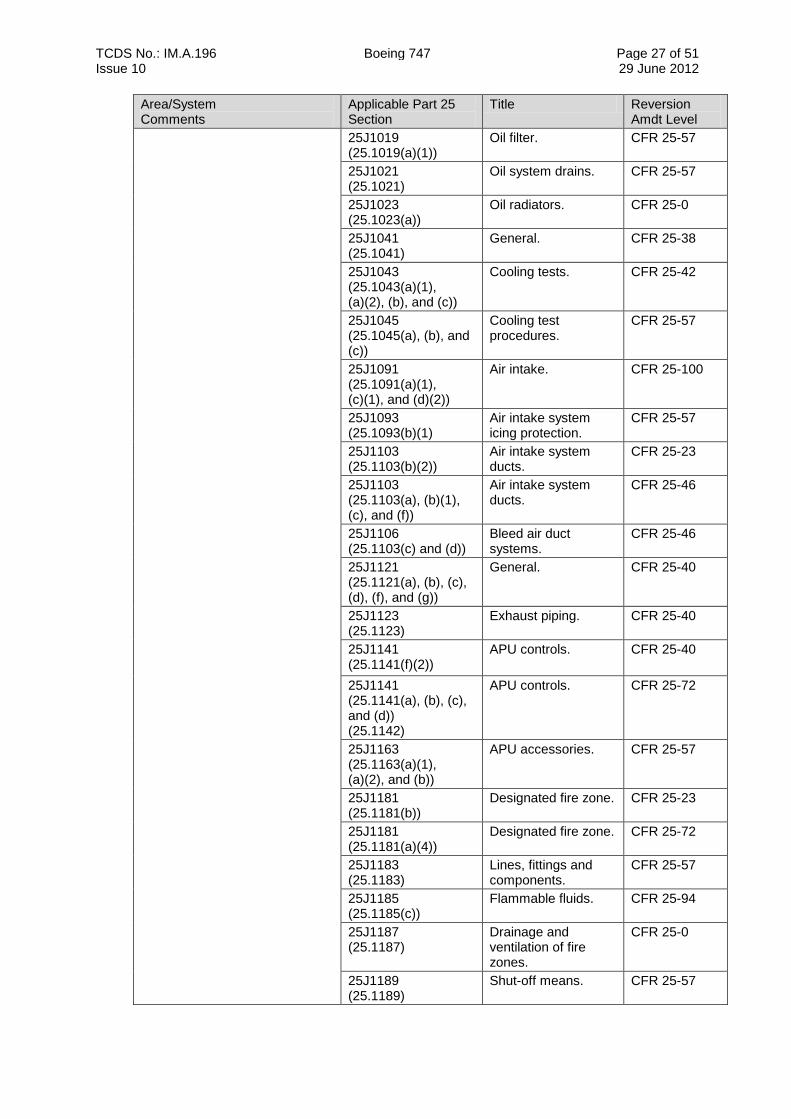
TCDS No.: IM.A.196 Boeing 747 Page 27 of 51 Issue 10 29 June 2012
Area/System Comments
Applicable Part 25 Section
Title Reversion Amdt Level
25J1019 (25.1019(a)(1))
Oil filter. CFR 25-57
25J1021 (25.1021)
Oil system drains. CFR 25-57
25J1023 (25.1023(a))
Oil radiators. CFR 25-0
25J1041 (25.1041)
General. CFR 25-38
25J1043 (25.1043(a)(1), (a)(2), (b), and (c))
Cooling tests. CFR 25-42
25J1045 (25.1045(a), (b), and (c))
Cooling test procedures.
CFR 25-57
25J1091 (25.1091(a)(1), (c)(1), and (d)(2))
Air intake. CFR 25-100
25J1093 (25.1093(b)(1)
Air intake system icing protection.
CFR 25-57
25J1103 (25.1103(b)(2))
Air intake system ducts.
CFR 25-23
25J1103 (25.1103(a), (b)(1), (c), and (f))
Air intake system ducts.
CFR 25-46
25J1106 (25.1103(c) and (d))
Bleed air duct systems.
CFR 25-46
25J1121 (25.1121(a), (b), (c), (d), (f), and (g))
General. CFR 25-40
25J1123 (25.1123)
Exhaust piping. CFR 25-40
25J1141 (25.1141(f)(2))
APU controls.
CFR 25-40
25J1141 (25.1141(a), (b), (c), and (d)) (25.1142)
APU controls. CFR 25-72
25J1163 (25.1163(a)(1), (a)(2), and (b))
APU accessories. CFR 25-57
25J1181 (25.1181(b))
Designated fire zone. CFR 25-23
25J1181 (25.1181(a)(4))
Designated fire zone. CFR 25-72
25J1183 (25.1183)
Lines, fittings and components.
CFR 25-57
25J1185 (25.1185(c))
Flammable fluids. CFR 25-94
25J1187 (25.1187)
Drainage and ventilation of fire zones.
CFR 25-0
25J1189 (25.1189)
Shut-off means. CFR 25-57
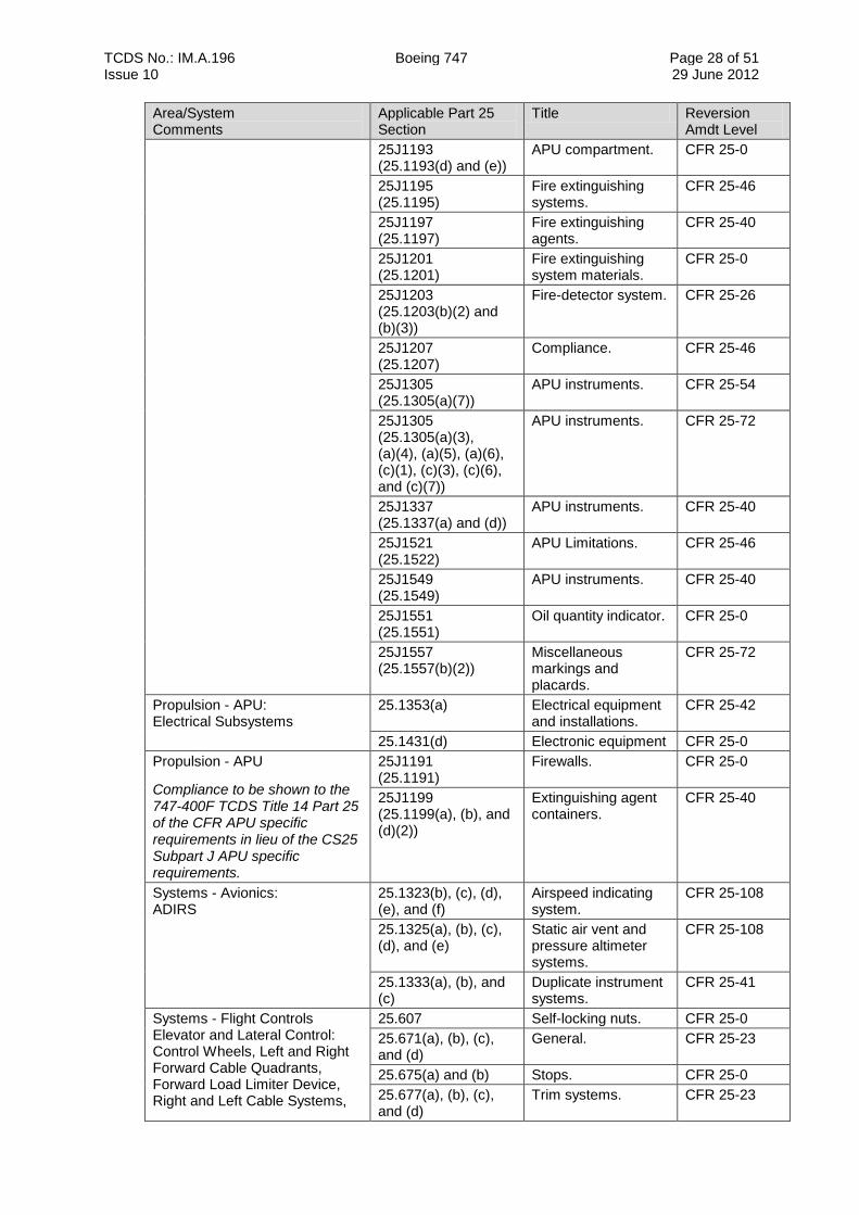
TCDS No.: IM.A.196 Boeing 747 Page 28 of 51 Issue 10 29 June 2012
Area/System Comments
Applicable Part 25 Section
Title Reversion Amdt Level
25J1193 (25.1193(d) and (e))
APU compartment. CFR 25-0
25J1195 (25.1195)
Fire extinguishing systems.
CFR 25-46
25J1197 (25.1197)
Fire extinguishing agents.
CFR 25-40
25J1201 (25.1201)
Fire extinguishing system materials.
CFR 25-0
25J1203 (25.1203(b)(2) and (b)(3))
Fire-detector system. CFR 25-26
25J1207 (25.1207)
Compliance. CFR 25-46
25J1305 (25.1305(a)(7))
APU instruments. CFR 25-54
25J1305 (25.1305(a)(3), (a)(4), (a)(5), (a)(6), (c)(1), (c)(3), (c)(6), and (c)(7))
APU instruments. CFR 25-72
25J1337 (25.1337(a) and (d))
APU instruments. CFR 25-40
25J1521 (25.1522)
APU Limitations. CFR 25-46
25J1549 (25.1549)
APU instruments. CFR 25-40
25J1551 (25.1551)
Oil quantity indicator. CFR 25-0
25J1557 (25.1557(b)(2))
Miscellaneous markings and placards.
CFR 25-72
Propulsion - APU: Electrical Subsystems
25.1353(a) Electrical equipment and installations.
CFR 25-42
25.1431(d) Electronic equipment CFR 25-0
Propulsion - APU
Compliance to be shown to the 747-400F TCDS Title 14 Part 25 of the CFR APU specific requirements in lieu of the CS25 Subpart J APU specific requirements.
25J1191 (25.1191)
Firewalls. CFR 25-0
25J1199 (25.1199(a), (b), and (d)(2))
Extinguishing agent containers.
CFR 25-40
Systems - Avionics: ADIRS
25.1323(b), (c), (d), (e), and (f)
Airspeed indicating system.
CFR 25-108
25.1325(a), (b), (c), (d), and (e)
Static air vent and pressure altimeter systems.
CFR 25-108
25.1333(a), (b), and (c)
Duplicate instrument systems.
CFR 25-41
Systems - Flight Controls Elevator and Lateral Control: Control Wheels, Left and Right Forward Cable Quadrants, Forward Load Limiter Device, Right and Left Cable Systems,
25.607 Self-locking nuts. CFR 25-0
25.671(a), (b), (c), and (d)
General. CFR 25-23
25.675(a) and (b) Stops. CFR 25-0
25.677(a), (b), (c), and (d)
Trim systems. CFR 25-23
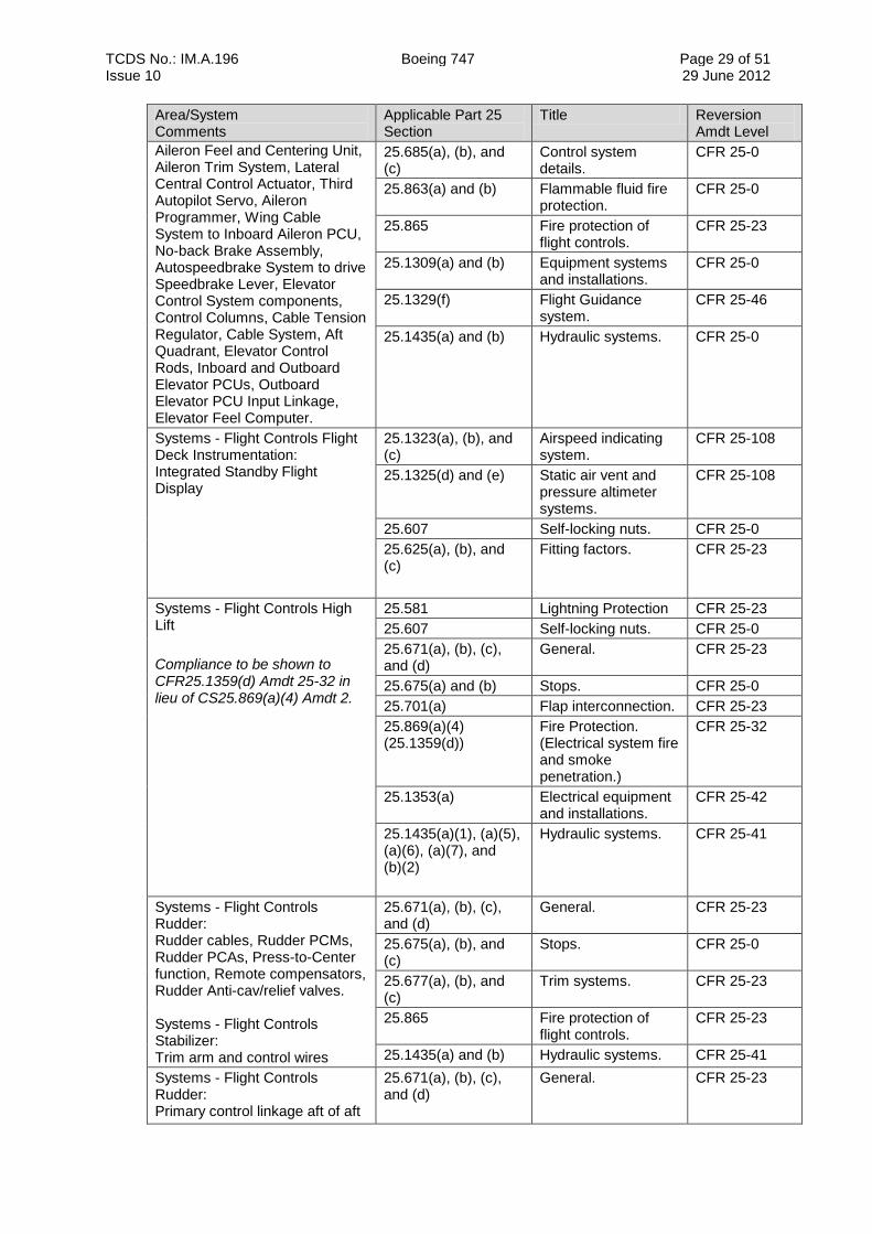
TCDS No.: IM.A.196 Boeing 747 Page 29 of 51 Issue 10 29 June 2012
Area/System Comments
Applicable Part 25 Section
Title Reversion Amdt Level
Aileron Feel and Centering Unit, Aileron Trim System, Lateral Central Control Actuator, Third Autopilot Servo, Aileron Programmer, Wing Cable System to Inboard Aileron PCU, No-back Brake Assembly, Autospeedbrake System to drive Speedbrake Lever, Elevator Control System components, Control Columns, Cable Tension Regulator, Cable System, Aft Quadrant, Elevator Control Rods, Inboard and Outboard Elevator PCUs, Outboard Elevator PCU Input Linkage, Elevator Feel Computer.
25.685(a), (b), and (c)
Control system details.
CFR 25-0
25.863(a) and (b) Flammable fluid fire protection.
CFR 25-0
25.865 Fire protection of flight controls.
CFR 25-23
25.1309(a) and (b) Equipment systems and installations.
CFR 25-0
25.1329(f) Flight Guidance system.
CFR 25-46
25.1435(a) and (b) Hydraulic systems. CFR 25-0
Systems - Flight Controls Flight Deck Instrumentation: Integrated Standby Flight Display
25.1323(a), (b), and (c)
Airspeed indicating system.
CFR 25-108
25.1325(d) and (e) Static air vent and pressure altimeter systems.
CFR 25-108
25.607 Self-locking nuts. CFR 25-0
25.625(a), (b), and (c)
Fitting factors.
CFR 25-23
Systems - Flight Controls High Lift
Compliance to be shown to CFR25.1359(d) Amdt 25-32 in lieu of CS25.869(a)(4) Amdt 2.
25.581 Lightning Protection CFR 25-23
25.607 Self-locking nuts. CFR 25-0
25.671(a), (b), (c), and (d)
General. CFR 25-23
25.675(a) and (b) Stops. CFR 25-0
25.701(a) Flap interconnection. CFR 25-23
25.869(a)(4) (25.1359(d))
Fire Protection. (Electrical system fire and smoke penetration.)
CFR 25-32
25.1353(a) Electrical equipment and installations.
CFR 25-42
25.1435(a)(1), (a)(5), (a)(6), (a)(7), and (b)(2)
Hydraulic systems. CFR 25-41
Systems - Flight Controls Rudder: Rudder cables, Rudder PCMs, Rudder PCAs, Press-to-Center function, Remote compensators, Rudder Anti-cav/relief valves. Systems - Flight Controls Stabilizer: Trim arm and control wires
25.671(a), (b), (c), and (d)
General. CFR 25-23
25.675(a), (b), and (c)
Stops. CFR 25-0
25.677(a), (b), and (c)
Trim systems. CFR 25-23
25.865 Fire protection of flight controls.
CFR 25-23
25.1435(a) and (b) Hydraulic systems. CFR 25-41
Systems - Flight Controls Rudder: Primary control linkage aft of aft
25.671(a), (b), (c), and (d)
General. CFR 25-23
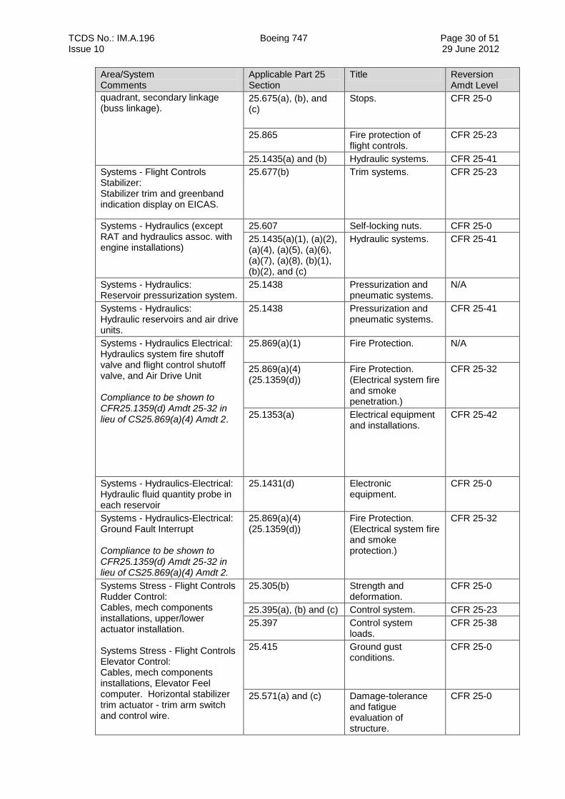
TCDS No.: IM.A.196 Boeing 747 Page 30 of 51 Issue 10 29 June 2012
Area/System Comments
Applicable Part 25 Section
Title Reversion Amdt Level
quadrant, secondary linkage (buss linkage).
25.675(a), (b), and (c)
Stops. CFR 25-0
25.865 Fire protection of flight controls.
CFR 25-23
25.1435(a) and (b) Hydraulic systems. CFR 25-41
Systems - Flight Controls Stabilizer: Stabilizer trim and greenband indication display on EICAS.
25.677(b) Trim systems. CFR 25-23
Systems - Hydraulics (except RAT and hydraulics assoc. with engine installations)
25.607 Self-locking nuts. CFR 25-0
25.1435(a)(1), (a)(2), (a)(4), (a)(5), (a)(6), (a)(7), (a)(8), (b)(1), (b)(2), and (c)
Hydraulic systems. CFR 25-41
Systems - Hydraulics: Reservoir pressurization system.
25.1438 Pressurization and pneumatic systems.
N/A
Systems - Hydraulics: Hydraulic reservoirs and air drive units.
25.1438 Pressurization and pneumatic systems.
CFR 25-41
Systems - Hydraulics Electrical: Hydraulics system fire shutoff valve and flight control shutoff valve, and Air Drive Unit Compliance to be shown to CFR25.1359(d) Amdt 25-32 in lieu of CS25.869(a)(4) Amdt 2.
25.869(a)(1) Fire Protection.
N/A
25.869(a)(4) (25.1359(d))
Fire Protection. (Electrical system fire and smoke penetration.)
CFR 25-32
25.1353(a) Electrical equipment and installations.
CFR 25-42
Systems - Hydraulics-Electrical: Hydraulic fluid quantity probe in each reservoir
25.1431(d) Electronic equipment.
CFR 25-0
Systems - Hydraulics-Electrical: Ground Fault Interrupt Compliance to be shown to CFR25.1359(d) Amdt 25-32 in lieu of CS25.869(a)(4) Amdt 2.
25.869(a)(4) (25.1359(d))
Fire Protection. (Electrical system fire and smoke protection.)
CFR 25-32
Systems Stress - Flight Controls Rudder Control: Cables, mech components installations, upper/lower actuator installation. Systems Stress - Flight Controls Elevator Control: Cables, mech components installations, Elevator Feel computer. Horizontal stabilizer trim actuator - trim arm switch and control wire.
25.305(b) Strength and deformation.
CFR 25-0
25.395(a), (b) and (c) Control system. CFR 25-23
25.397 Control system loads.
CFR 25-38
25.415 Ground gust conditions.
CFR 25-0
25.571(a) and (c) Damage-tolerance and fatigue evaluation of structure.
CFR 25-0
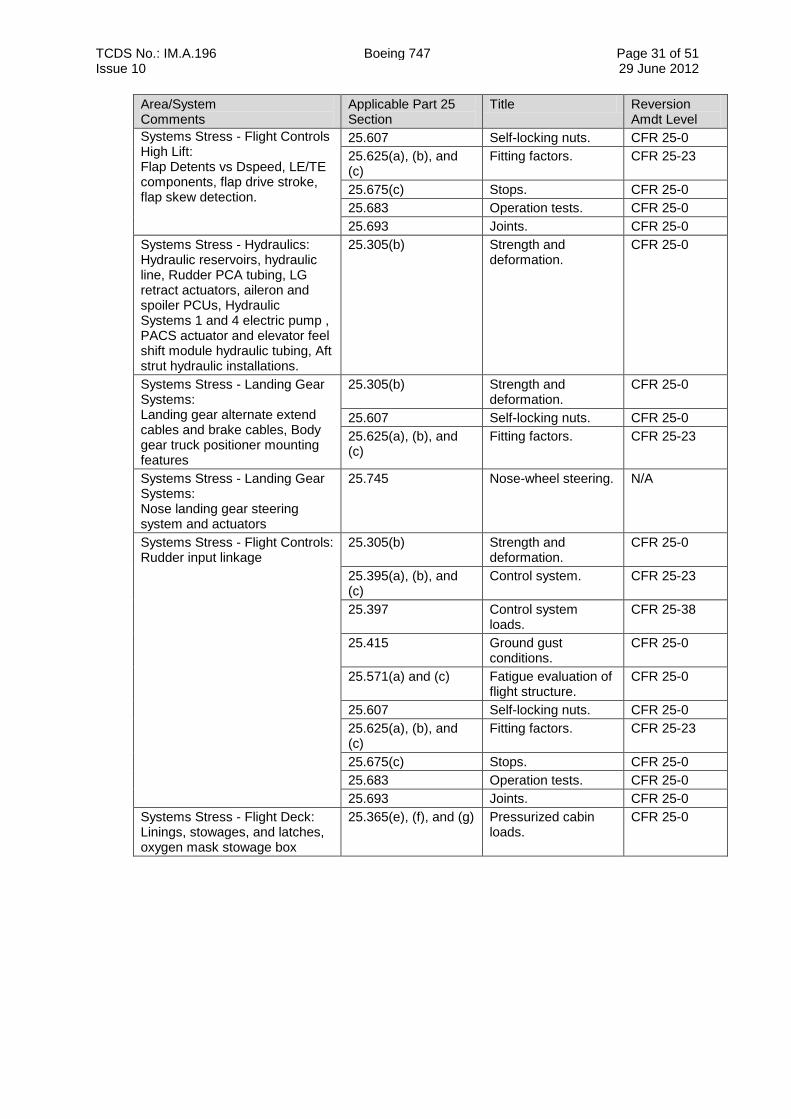
TCDS No.: IM.A.196 Boeing 747 Page 31 of 51 Issue 10 29 June 2012
Area/System Comments
Applicable Part 25 Section
Title Reversion Amdt Level
Systems Stress - Flight Controls High Lift: Flap Detents vs Dspeed, LE/TE components, flap drive stroke, flap skew detection.
25.607 Self-locking nuts. CFR 25-0
25.625(a), (b), and (c)
Fitting factors. CFR 25-23
25.675(c) Stops. CFR 25-0
25.683 Operation tests. CFR 25-0
25.693 Joints. CFR 25-0
Systems Stress - Hydraulics: Hydraulic reservoirs, hydraulic line, Rudder PCA tubing, LG retract actuators, aileron and spoiler PCUs, Hydraulic Systems 1 and 4 electric pump , PACS actuator and elevator feel shift module hydraulic tubing, Aft strut hydraulic installations.
25.305(b) Strength and deformation.
CFR 25-0
Systems Stress - Landing Gear Systems: Landing gear alternate extend cables and brake cables, Body gear truck positioner mounting features
25.305(b) Strength and deformation.
CFR 25-0
25.607 Self-locking nuts. CFR 25-0
25.625(a), (b), and (c)
Fitting factors. CFR 25-23
Systems Stress - Landing Gear Systems: Nose landing gear steering system and actuators
25.745 Nose-wheel steering. N/A
Systems Stress - Flight Controls: Rudder input linkage
25.305(b) Strength and deformation.
CFR 25-0
25.395(a), (b), and (c)
Control system. CFR 25-23
25.397 Control system loads.
CFR 25-38
25.415 Ground gust conditions.
CFR 25-0
25.571(a) and (c) Fatigue evaluation of flight structure.
CFR 25-0
25.607 Self-locking nuts. CFR 25-0
25.625(a), (b), and (c)
Fitting factors. CFR 25-23
25.675(c) Stops. CFR 25-0
25.683 Operation tests. CFR 25-0
25.693 Joints. CFR 25-0
Systems Stress - Flight Deck: Linings, stowages, and latches, oxygen mask stowage box
25.365(e), (f), and (g) Pressurized cabin loads.
CFR 25-0
TCDS No.: IM.A.196 Boeing 747 Page 32 of 51 Issue 10 29 June 2012
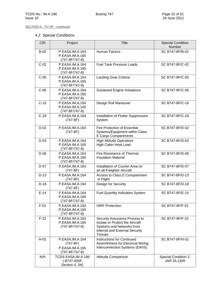
SECTION 6: 747-8F - continued
4.2 Special Conditions
CRI Project Title Special Condition Number
B-02 P.EASA.IM.A.164 P.EASA.IM.A.165
(747-8F/747-8)
Human Factors SC B747-8F/B-02
C-02 P.EASA.IM.A.164 P.EASA.IM.A.165
(747-8F/747-8)
Fuel Tank Pressure Loads SC B747-8F/C-02
C-05 P.EASA.IM.A.164 P.EASA.IM.A.165
(747-8F/747-8)
Landing Gear Criteria SC B747-8F/C-05
C-06 P.EASA.IM.A.164 P.EASA.IM.A.165
(747-8F/747-8)
Sustained Engine Imbalance SC B747-8F/C-06
C-16 P.EASA.IM.A.164 P.EASA.IM.A.165
(747-8F/747-8)
Design Roll Maneuver SC B747-8F/C-16
C-18 P.EASA.IM.A.164 (747-8F)
Installation of Flutter Suppression System
SC B747-8F/C-18
D-02 P.EASA.IM.A.164 (747-8F)
Fire Protection of Essential Systems/Equipment within Class E Cargo Compartments
SC B747-8F/D-02
D-03 P.EASA.IM.A.164 P.EASA.IM.A.165
(747-8F/747-8)
High Altitude Operation/ High Cabin Heat Load
SC B747-8F/D-03
D-06 P.EASA.IM.A.164 P.EASA.IM.A.165
(747-8F/747-8)
Fire Resistance of Thermal Insulation Material
SC B747-8F/D-06
D-07 P.EASA.IM.A.164 (747-8F)
Installation of Courier Area on an all Freighter Aircraft
SC B747-8F/D-07
D-13 P.EASA.IM.A.164 (747-8F)
Access to Class E Compartment in Flight
SC B747-8F/D-13
D-18 P.EASA.IM.A.164 (747-8F)
Design for Security SC B747-8F/D-18
E-14 P.EASA.IM.A.164 P.EASA.IM.A.165
(747-8F/747-8)
Fuel Quantity Indication System SC B747-8F/E-14
F-01 P.EASA.IM.A.164 P.EASA.IM.A.165
(747-8F/747-8)
HIRF Protection SC B747-8F/F-01
F-22 P.EASA.IM.A.164 P.EASA.IM.A.165
(747-8F/747-8)
Security Assurance Process to Isolate or Protect the Aircraft Systems and Networks from Internal and External Security Threats
SC B747-8F/F-22
H-01 P.EASA.IM.A.164 (747-8F)
P.EASA.IM.A.165 (747-8F/747-8)
Instructions for Continued Airworthiness for Electrical Wiring Interconnection Systems (EWIS)
SC B747-8F/H-01
N/A TCDS EASA.IM.A.196 ( B747-400F, Section 4, 3A)
Attitude Comparison Special Condition 2: JAR 25.1309
TCDS No.: IM.A.196 Boeing 747 Page 33 of 51 Issue 10 29 June 2012
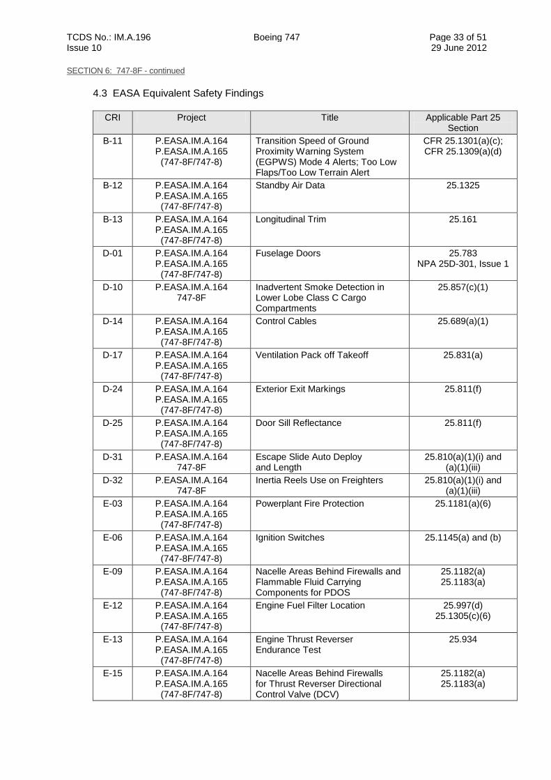
SECTION 6: 747-8F - continued
4.3 EASA Equivalent Safety Findings
CRI Project Title Applicable Part 25 Section
B-11 P.EASA.IM.A.164 P.EASA.IM.A.165
(747-8F/747-8)
Transition Speed of Ground Proximity Warning System (EGPWS) Mode 4 Alerts; Too Low Flaps/Too Low Terrain Alert
CFR 25.1301(a)(c); CFR 25.1309(a)(d)
B-12 P.EASA.IM.A.164 P.EASA.IM.A.165
(747-8F/747-8)
Standby Air Data 25.1325
B-13 P.EASA.IM.A.164 P.EASA.IM.A.165
(747-8F/747-8)
Longitudinal Trim 25.161
D-01 P.EASA.IM.A.164 P.EASA.IM.A.165
(747-8F/747-8)
Fuselage Doors 25.783 NPA 25D-301, Issue 1
D-10 P.EASA.IM.A.164 747-8F
Inadvertent Smoke Detection in Lower Lobe Class C Cargo Compartments
25.857(c)(1)
D-14 P.EASA.IM.A.164 P.EASA.IM.A.165
(747-8F/747-8)
Control Cables 25.689(a)(1)
D-17 P.EASA.IM.A.164 P.EASA.IM.A.165
(747-8F/747-8)
Ventilation Pack off Takeoff 25.831(a)
D-24 P.EASA.IM.A.164 P.EASA.IM.A.165
(747-8F/747-8)
Exterior Exit Markings 25.811(f)
D-25 P.EASA.IM.A.164 P.EASA.IM.A.165
(747-8F/747-8)
Door Sill Reflectance 25.811(f)
D-31 P.EASA.IM.A.164 747-8F
Escape Slide Auto Deploy and Length
25.810(a)(1)(i) and (a)(1)(iii)
D-32 P.EASA.IM.A.164 747-8F
Inertia Reels Use on Freighters 25.810(a)(1)(i) and (a)(1)(iii)
E-03 P.EASA.IM.A.164 P.EASA.IM.A.165
(747-8F/747-8)
Powerplant Fire Protection 25.1181(a)(6)
E-06 P.EASA.IM.A.164 P.EASA.IM.A.165
(747-8F/747-8)
Ignition Switches 25.1145(a) and (b)
E-09 P.EASA.IM.A.164 P.EASA.IM.A.165
(747-8F/747-8)
Nacelle Areas Behind Firewalls and Flammable Fluid Carrying Components for PDOS
25.1182(a) 25.1183(a)
E-12 P.EASA.IM.A.164 P.EASA.IM.A.165
(747-8F/747-8)
Engine Fuel Filter Location 25.997(d) 25.1305(c)(6)
E-13 P.EASA.IM.A.164 P.EASA.IM.A.165
(747-8F/747-8)
Engine Thrust Reverser Endurance Test
25.934
E-15 P.EASA.IM.A.164 P.EASA.IM.A.165
(747-8F/747-8)
Nacelle Areas Behind Firewalls for Thrust Reverser Directional Control Valve (DCV)
25.1182(a) 25.1183(a)
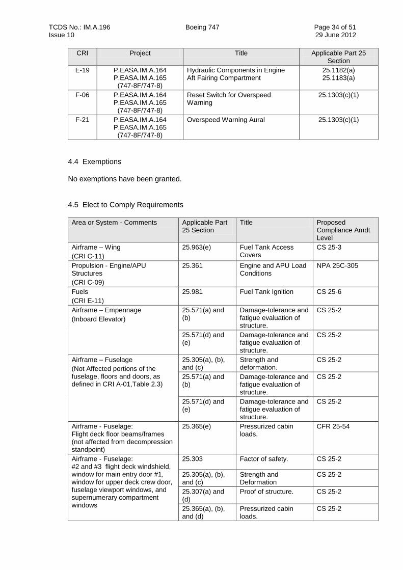
TCDS No.: IM.A.196 Boeing 747 Page 34 of 51 Issue 10 29 June 2012
CRI Project Title Applicable Part 25 Section
E-19 P.EASA.IM.A.164 P.EASA.IM.A.165
(747-8F/747-8)
Hydraulic Components in Engine Aft Fairing Compartment
25.1182(a) 25.1183(a)
F-06 P.EASA.IM.A.164 P.EASA.IM.A.165
(747-8F/747-8)
Reset Switch for Overspeed Warning
25.1303(c)(1)
F-21 P.EASA.IM.A.164 P.EASA.IM.A.165
(747-8F/747-8)
Overspeed Warning Aural 25.1303(c)(1)
4.4 Exemptions
No exemptions have been granted.
4.5 Elect to Comply Requirements
Area or System - Comments Applicable Part 25 Section
Title Proposed Compliance Amdt Level
Airframe – Wing
(CRI C-11)
25.963(e) Fuel Tank Access Covers
CS 25-3
Propulsion - Engine/APU Structures
(CRI C-09)
25.361 Engine and APU Load Conditions
NPA 25C-305
Fuels
(CRI E-11)
25.981 Fuel Tank Ignition CS 25-6
Airframe – Empennage
(Inboard Elevator)
25.571(a) and (b)
Damage-tolerance and fatigue evaluation of structure.
CS 25-2
25.571(d) and (e)
Damage-tolerance and fatigue evaluation of structure.
CS 25-2
Airframe – Fuselage
(Not Affected portions of the fuselage, floors and doors, as defined in CRI A-01,Table 2.3)
25.305(a), (b), and (c)
Strength and deformation.
CS 25-2
25.571(a) and (b)
Damage-tolerance and fatigue evaluation of structure.
CS 25-2
25.571(d) and (e)
Damage-tolerance and fatigue evaluation of structure.
CS 25-2
Airframe - Fuselage: Flight deck floor beams/frames (not affected from decompression standpoint)
25.365(e) Pressurized cabin loads.
CFR 25-54
Airframe - Fuselage: #2 and #3 flight deck windshield, window for main entry door #1, window for upper deck crew door, fuselage viewport windows, and supernumerary compartment windows
25.303 Factor of safety. CS 25-2
25.305(a), (b), and (c)
Strength and Deformation
CS 25-2
25.307(a) and (d)
Proof of structure. CS 25-2
25.365(a), (b), and (d)
Pressurized cabin loads.
CS 25-2
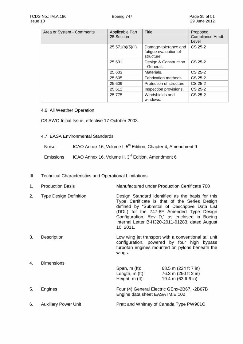
TCDS No.: IM.A.196 Boeing 747 Page 35 of 51 Issue 10 29 June 2012
Area or System - Comments Applicable Part 25 Section
Title Proposed Compliance Amdt Level
25.571(b)(5)(ii) Damage-tolerance and fatigue evaluation of structure.
CS 25-2
25.601 Design & Construction - General.
CS 25-2
25.603 Materials. CS 25-2
25.605 Fabrication methods. CS 25-2
25.609 Protection of structure. CS 25-2
25.611 Inspection provisions. CS 25-2
25.775 Windshields and windows.
CS 25-2
4.6 All Weather Operation
CS AWO Initial Issue, effective 17 October 2003.
4.7 EASA Environmental Standards Noise ICAO Annex 16, Volume I, 5
th Edition, Chapter 4, Amendment 9
Emissions ICAO Annex 16, Volume II, 3
rd Edition, Amendment 6
III. Technical Characteristics and Operational Limitations 1. Production Basis Manufactured under Production Certificate 700
2. Type Design Definition Design Standard identified as the basis for this Type Certificate is that of the Series Design defined by “Submittal of Descriptive Data List (DDL) for the 747-8F Amended Type Design Configuration, Rev D,” as enclosed in Boeing Internal Letter B-H320-2011-01283, dated August 10, 2011.
3. Description Low wing jet transport with a conventional tail unit configuration, powered by four high bypass turbofan engines mounted on pylons beneath the wings.
4. Dimensions
Span, m (ft): 68.5 m (224 ft 7 in) Length, m (ft): 76.3 m (250 ft 2 in) Height, m (ft): 19.4 m (63 ft 6 in)
5. Engines Four (4) General Electric GEnx-2B67, -2B67B
Engine data sheet EASA IM.E.102
6. Auxiliary Power Unit Pratt and Whitney of Canada Type PW901C
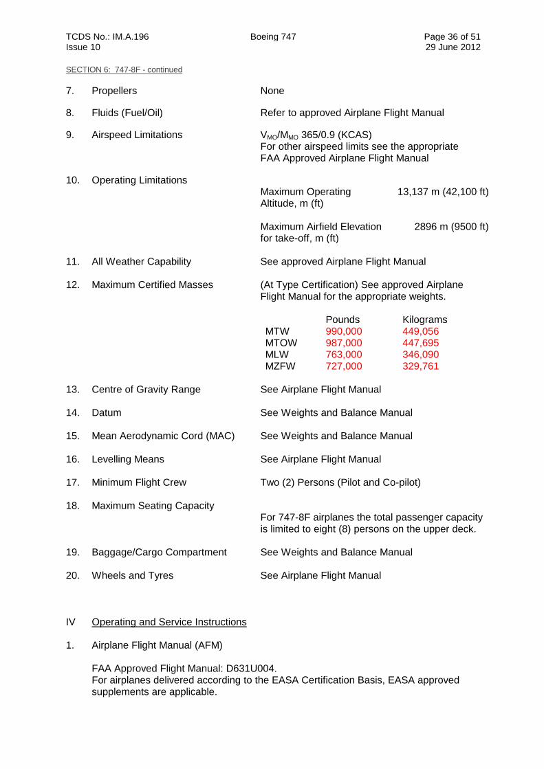
TCDS No.: IM.A.196 Boeing 747 Page 36 of 51 Issue 10 29 June 2012
SECTION 6: 747-8F - continued
7. Propellers None
8. Fluids (Fuel/Oil) Refer to approved Airplane Flight Manual
9. Airspeed Limitations VMO/MMO 365/0.9 (KCAS) For other airspeed limits see the appropriate FAA Approved Airplane Flight Manual
10. Operating Limitations Maximum Operating Altitude, m (ft)
13,137 m (42,100 ft)
Maximum Airfield Elevation for take-off, m (ft)
2896 m (9500 ft)
11. All Weather Capability See approved Airplane Flight Manual
12. Maximum Certified Masses (At Type Certification) See approved Airplane
Flight Manual for the appropriate weights. Pounds Kilograms MTW 990,000 449,056 MTOW 987,000 447,695 MLW 763,000 346,090 MZFW 727,000 329,761
13. Centre of Gravity Range See Airplane Flight Manual
14. Datum See Weights and Balance Manual 15. Mean Aerodynamic Cord (MAC) See Weights and Balance Manual 16. Levelling Means See Airplane Flight Manual
17. Minimum Flight Crew Two (2) Persons (Pilot and Co-pilot) 18. Maximum Seating Capacity
For 747-8F airplanes the total passenger capacity is limited to eight (8) persons on the upper deck.
19. Baggage/Cargo Compartment See Weights and Balance Manual
20. Wheels and Tyres See Airplane Flight Manual
IV Operating and Service Instructions 1. Airplane Flight Manual (AFM)
FAA Approved Flight Manual: D631U004. For airplanes delivered according to the EASA Certification Basis, EASA approved supplements are applicable.
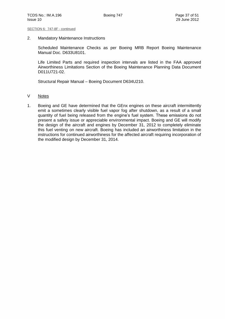
TCDS No.: IM.A.196 Boeing 747 Page 37 of 51 Issue 10 29 June 2012
SECTION 6: 747-8F - continued
2. Mandatory Maintenance Instructions
Scheduled Maintenance Checks as per Boeing MRB Report Boeing Maintenance Manual Doc. D633U8101.
Life Limited Parts and required inspection intervals are listed in the FAA approved Airworthiness Limitations Section of the Boeing Maintenance Planning Data Document D011U721-02. Structural Repair Manual – Boeing Document D634U210.
V Notes 1. Boeing and GE have determined that the GEnx engines on these aircraft intermittently
emit a sometimes clearly visible fuel vapor fog after shutdown, as a result of a small quantity of fuel being released from the engine’s fuel system. These emissions do not present a safety issue or appreciable environmental impact. Boeing and GE will modify the design of the aircraft and engines by December 31, 2012 to completely eliminate this fuel venting on new aircraft. Boeing has included an airworthiness limitation in the instructions for continued airworthiness for the affected aircraft requiring incorporation of the modified design by December 31, 2014.
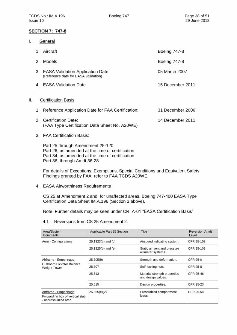
TCDS No.: IM.A.196 Boeing 747 Page 38 of 51 Issue 10 29 June 2012
SECTION 7: 747-8 I. General
1. Aircraft Boeing 747-8
2. Models Boeing 747-8
3. EASA Validation Application Date 05 March 2007 (Reference date for EASA validation)
4. EASA Validation Date 15 December 2011 II. Certification Basis
1. Reference Application Date for FAA Certification: 31 December 2006 2. Certification Date: 14 December 2011
(FAA Type Certification Data Sheet No. A20WE)
3. FAA Certification Basis:
Part 25 through Amendment 25-120 Part 26, as amended at the time of certification Part 34, as amended at the time of certification Part 36, through Amdt 36-28 For details of Exceptions, Exemptions, Special Conditions and Equivalent Safety Findings granted by FAA, refer to FAA TCDS A20WE.
4. EASA Airworthiness Requirements
CS 25 at Amendment 2 and, for unaffected areas, Boeing 747-400 EASA Type Certification Data Sheet IM.A.196 (Section 3 above),
Note: Further details may be seen under CRI A-01 “EASA Certification Basis”
4.1 Reversions from CS 25 Amendment 2:
Area/System Comments
Applicable Part 25 Section Title Reversion Amdt Level
Aero - Configurations
25.1323(b) and (c) Airspeed indicating system. CFR 25-108
25.1325(b) and (e) Static air vent and pressure altimeter systems.
CFR 25-108
Airframe - Empennage:
Outboard Elevator Balance Weight Tower
25.305(b) Strength and deformation. CFR 25-0
25.607 Self-locking nuts. CFR 25-0
25.613 Material strength properties and design values.
CFR 25-46
25.615 Design properties. CFR 25-23
Airframe - Empennage:
Forward fin box of vertical stab - unpressurized area
25.365(e)(2) Pressurized compartment loads.
CFR 25-54
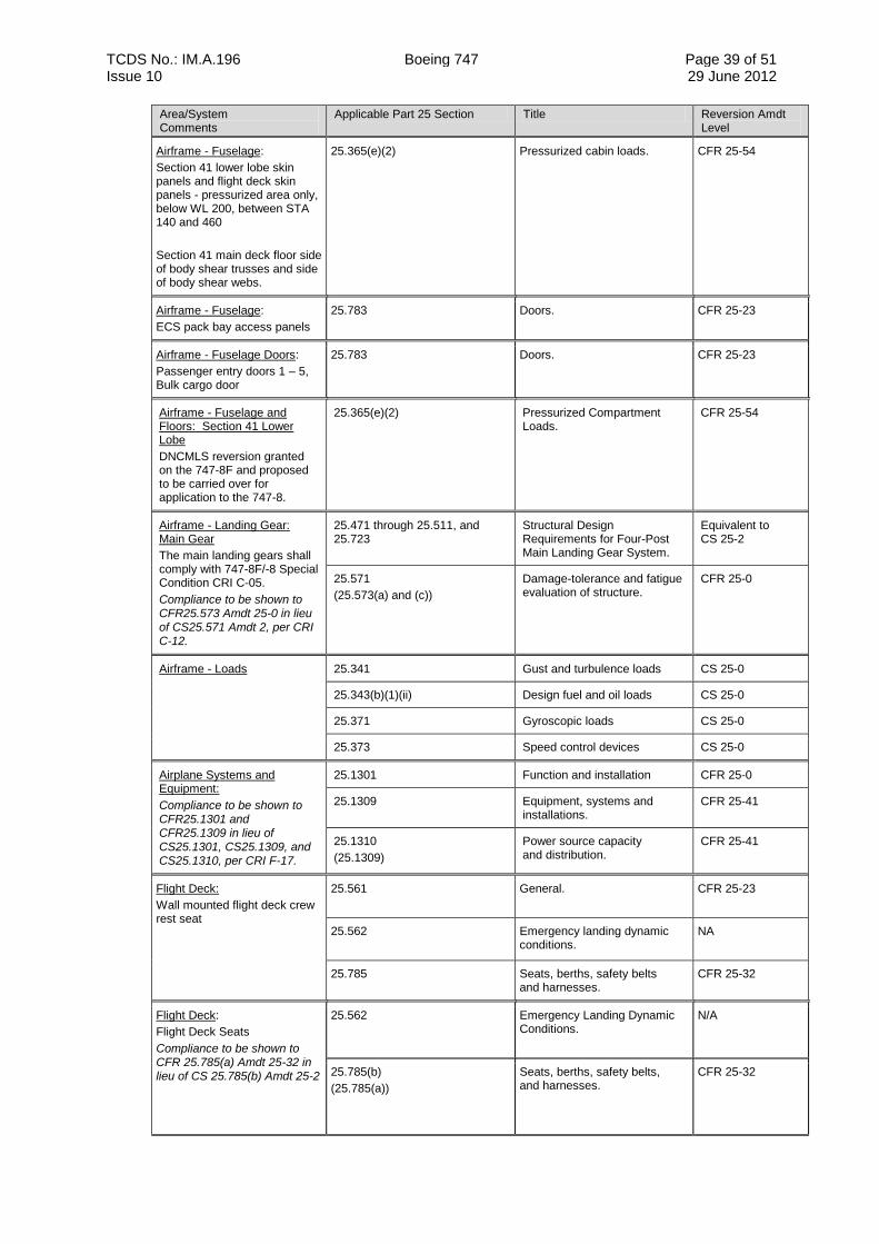
TCDS No.: IM.A.196 Boeing 747 Page 39 of 51 Issue 10 29 June 2012
Area/System Comments
Applicable Part 25 Section Title Reversion Amdt Level
Airframe - Fuselage:
Section 41 lower lobe skin panels and flight deck skin panels - pressurized area only, below WL 200, between STA 140 and 460
Section 41 main deck floor side of body shear trusses and side of body shear webs.
25.365(e)(2) Pressurized cabin loads. CFR 25-54
Airframe - Fuselage:
ECS pack bay access panels
25.783 Doors. CFR 25-23
Airframe - Fuselage Doors:
Passenger entry doors 1 – 5, Bulk cargo door
25.783 Doors. CFR 25-23
Airframe - Fuselage and Floors: Section 41 Lower Lobe
DNCMLS reversion granted on the 747-8F and proposed to be carried over for application to the 747-8.
25.365(e)(2) Pressurized Compartment Loads.
CFR 25-54
Airframe - Landing Gear: Main Gear
The main landing gears shall comply with 747-8F/-8 Special Condition CRI C-05.
Compliance to be shown to CFR25.573 Amdt 25-0 in lieu of CS25.571 Amdt 2, per CRI C-12.
25.471 through 25.511, and 25.723
Structural Design Requirements for Four-Post Main Landing Gear System.
Equivalent to CS 25-2
25.571
(25.573(a) and (c))
Damage-tolerance and fatigue evaluation of structure.
CFR 25-0
Airframe - Loads 25.341 Gust and turbulence loads CS 25-0
25.343(b)(1)(ii) Design fuel and oil loads CS 25-0
25.371 Gyroscopic loads CS 25-0
25.373 Speed control devices CS 25-0
Airplane Systems and Equipment:
Compliance to be shown to CFR25.1301 and CFR25.1309 in lieu of CS25.1301, CS25.1309, and CS25.1310, per CRI F-17.
25.1301 Function and installation CFR 25-0
25.1309 Equipment, systems and installations.
CFR 25-41
25.1310
(25.1309)
Power source capacity and distribution.
CFR 25-41
Flight Deck:
Wall mounted flight deck crew rest seat
25.561 General.
CFR 25-23
25.562
Emergency landing dynamic conditions.
NA
25.785 Seats, berths, safety belts and harnesses.
CFR 25-32
Flight Deck:
Flight Deck Seats
Compliance to be shown to CFR 25.785(a) Amdt 25-32 in lieu of CS 25.785(b) Amdt 25-2
25.562 Emergency Landing Dynamic Conditions.
N/A
25.785(b)
(25.785(a))
Seats, berths, safety belts, and harnesses.
CFR 25-32
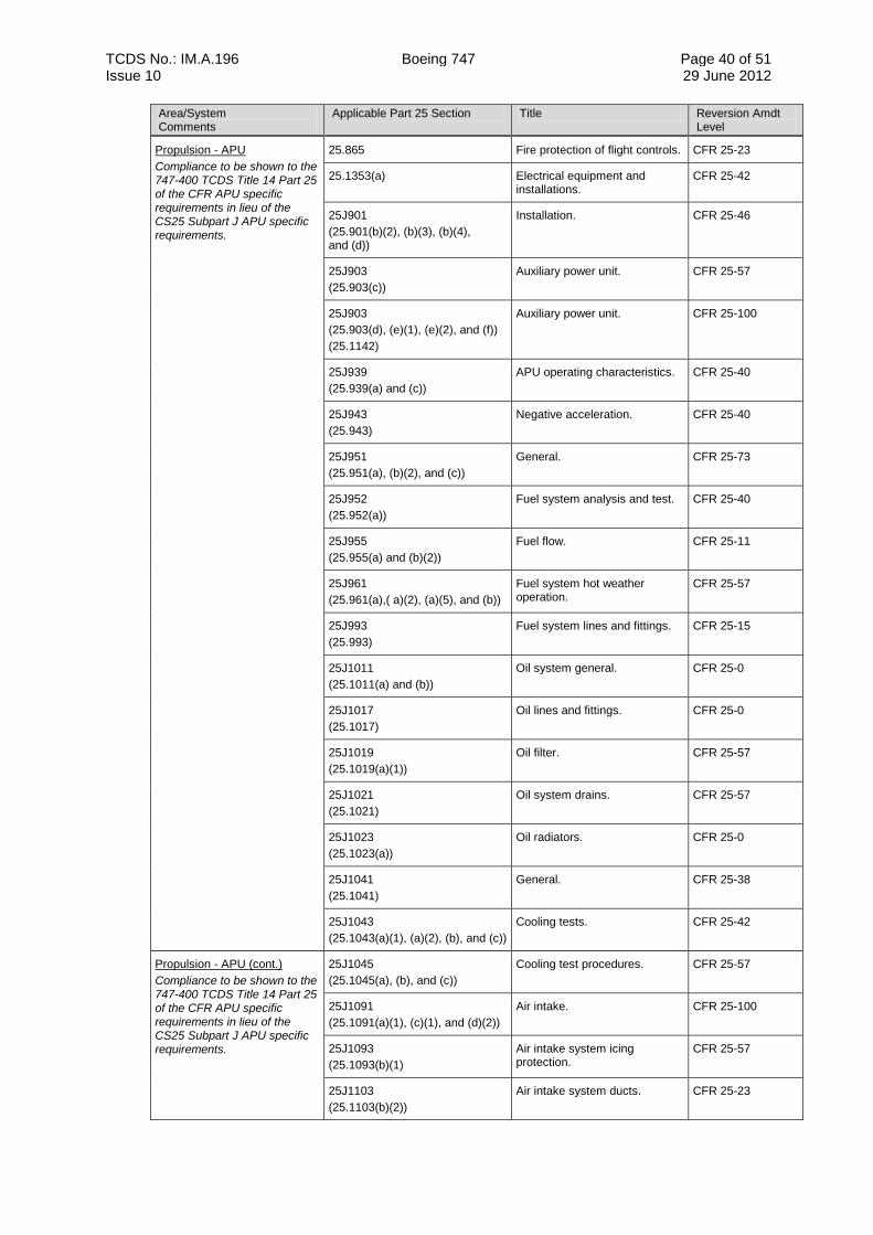
TCDS No.: IM.A.196 Boeing 747 Page 40 of 51 Issue 10 29 June 2012
Area/System Comments
Applicable Part 25 Section Title Reversion Amdt Level
Propulsion - APU
Compliance to be shown to the 747-400 TCDS Title 14 Part 25 of the CFR APU specific requirements in lieu of the CS25 Subpart J APU specific requirements.
25.865 Fire protection of flight controls. CFR 25-23
25.1353(a) Electrical equipment and installations.
CFR 25-42
25J901
(25.901(b)(2), (b)(3), (b)(4), and (d))
Installation. CFR 25-46
25J903
(25.903(c))
Auxiliary power unit. CFR 25-57
25J903
(25.903(d), (e)(1), (e)(2), and (f))
(25.1142)
Auxiliary power unit. CFR 25-100
25J939
(25.939(a) and (c))
APU operating characteristics. CFR 25-40
25J943
(25.943)
Negative acceleration. CFR 25-40
25J951
(25.951(a), (b)(2), and (c))
General. CFR 25-73
25J952
(25.952(a))
Fuel system analysis and test. CFR 25-40
25J955
(25.955(a) and (b)(2))
Fuel flow. CFR 25-11
25J961
(25.961(a),( a)(2), (a)(5), and (b))
Fuel system hot weather operation.
CFR 25-57
25J993
(25.993)
Fuel system lines and fittings. CFR 25-15
25J1011
(25.1011(a) and (b))
Oil system general. CFR 25-0
25J1017
(25.1017)
Oil lines and fittings. CFR 25-0
25J1019
(25.1019(a)(1))
Oil filter. CFR 25-57
25J1021
(25.1021)
Oil system drains. CFR 25-57
25J1023
(25.1023(a))
Oil radiators. CFR 25-0
25J1041
(25.1041)
General. CFR 25-38
25J1043
(25.1043(a)(1), (a)(2), (b), and (c))
Cooling tests. CFR 25-42
Propulsion - APU (cont.)
Compliance to be shown to the 747-400 TCDS Title 14 Part 25 of the CFR APU specific requirements in lieu of the CS25 Subpart J APU specific requirements.
25J1045
(25.1045(a), (b), and (c))
Cooling test procedures. CFR 25-57
25J1091
(25.1091(a)(1), (c)(1), and (d)(2))
Air intake. CFR 25-100
25J1093
(25.1093(b)(1)
Air intake system icing protection.
CFR 25-57
25J1103
(25.1103(b)(2))
Air intake system ducts. CFR 25-23
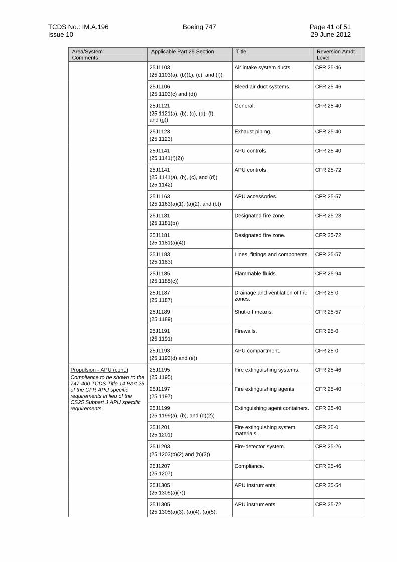
TCDS No.: IM.A.196 Boeing 747 Page 41 of 51 Issue 10 29 June 2012
Area/System Comments
Applicable Part 25 Section Title Reversion Amdt Level
25J1103
(25.1103(a), (b)(1), (c), and (f))
Air intake system ducts. CFR 25-46
25J1106
(25.1103(c) and (d))
Bleed air duct systems. CFR 25-46
25J1121
(25.1121(a), (b), (c), (d), (f), and (g))
General. CFR 25-40
25J1123
(25.1123)
Exhaust piping. CFR 25-40
25J1141
(25.1141(f)(2))
APU controls. CFR 25-40
25J1141
(25.1141(a), (b), (c), and (d))
(25.1142)
APU controls. CFR 25-72
25J1163
(25.1163(a)(1), (a)(2), and (b))
APU accessories. CFR 25-57
25J1181
(25.1181(b))
Designated fire zone. CFR 25-23
25J1181
(25.1181(a)(4))
Designated fire zone. CFR 25-72
25J1183
(25.1183)
Lines, fittings and components. CFR 25-57
25J1185
(25.1185(c))
Flammable fluids. CFR 25-94
25J1187
(25.1187)
Drainage and ventilation of fire zones.
CFR 25-0
25J1189
(25.1189)
Shut-off means. CFR 25-57
25J1191
(25.1191)
Firewalls. CFR 25-0
25J1193
(25.1193(d) and (e))
APU compartment. CFR 25-0
Propulsion - APU (cont.)
Compliance to be shown to the 747-400 TCDS Title 14 Part 25 of the CFR APU specific requirements in lieu of the CS25 Subpart J APU specific requirements.
25J1195
(25.1195)
Fire extinguishing systems. CFR 25-46
25J1197
(25.1197)
Fire extinguishing agents. CFR 25-40
25J1199
(25.1199(a), (b), and (d)(2))
Extinguishing agent containers. CFR 25-40
25J1201
(25.1201)
Fire extinguishing system materials.
CFR 25-0
25J1203
(25.1203(b)(2) and (b)(3))
Fire-detector system. CFR 25-26
25J1207
(25.1207)
Compliance. CFR 25-46
25J1305
(25.1305(a)(7))
APU instruments. CFR 25-54
25J1305
(25.1305(a)(3), (a)(4), (a)(5),
APU instruments. CFR 25-72
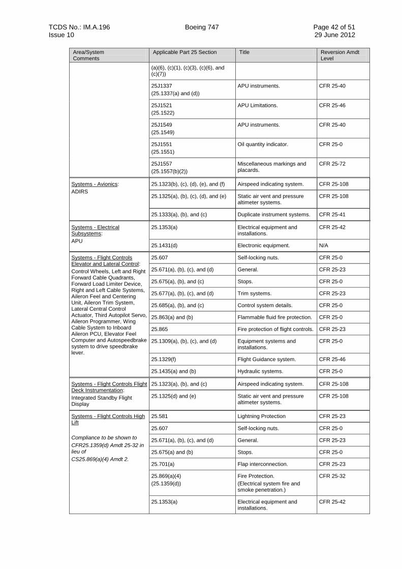
TCDS No.: IM.A.196 Boeing 747 Page 42 of 51 Issue 10 29 June 2012
Area/System Comments
Applicable Part 25 Section Title Reversion Amdt Level
(a)(6), (c)(1), (c)(3), (c)(6), and (c)(7))
25J1337
(25.1337(a) and (d))
APU instruments. CFR 25-40
25J1521
(25.1522)
APU Limitations. CFR 25-46
25J1549
(25.1549)
APU instruments. CFR 25-40
25J1551
(25.1551)
Oil quantity indicator. CFR 25-0
25J1557
(25.1557(b)(2))
Miscellaneous markings and placards.
CFR 25-72
Systems - Avionics:
ADIRS
25.1323(b), (c), (d), (e), and (f) Airspeed indicating system. CFR 25-108
25.1325(a), (b), (c), (d), and (e) Static air vent and pressure altimeter systems.
CFR 25-108
25.1333(a), (b), and (c) Duplicate instrument systems. CFR 25-41
Systems - Electrical Subsystems:
APU
25.1353(a) Electrical equipment and installations.
CFR 25-42
25.1431(d) Electronic equipment. N/A
Systems - Flight Controls Elevator and Lateral Control:
Control Wheels, Left and Right Forward Cable Quadrants, Forward Load Limiter Device, Right and Left Cable Systems, Aileron Feel and Centering Unit, Aileron Trim System, Lateral Central Control Actuator, Third Autopilot Servo, Aileron Programmer, Wing Cable System to Inboard Aileron PCU, Elevator Feel Computer and Autospeedbrake system to drive speedbrake lever.
25.607 Self-locking nuts. CFR 25-0
25.671(a), (b), (c), and (d) General. CFR 25-23
25.675(a), (b), and (c) Stops. CFR 25-0
25.677(a), (b), (c), and (d) Trim systems. CFR 25-23
25.685(a), (b), and (c) Control system details. CFR 25-0
25.863(a) and (b) Flammable fluid fire protection. CFR 25-0
25.865 Fire protection of flight controls. CFR 25-23
25.1309(a), (b), (c), and (d) Equipment systems and installations.
CFR 25-0
25.1329(f) Flight Guidance system. CFR 25-46
25.1435(a) and (b) Hydraulic systems. CFR 25-0
Systems - Flight Controls Flight Deck Instrumentation:
Integrated Standby Flight Display
25.1323(a), (b), and (c) Airspeed indicating system. CFR 25-108
25.1325(d) and (e) Static air vent and pressure altimeter systems.
CFR 25-108
Systems - Flight Controls High Lift
Compliance to be shown to
CFR25.1359(d) Amdt 25-32 in lieu of
CS25.869(a)(4) Amdt 2.
25.581 Lightning Protection CFR 25-23
25.607 Self-locking nuts. CFR 25-0
25.671(a), (b), (c), and (d) General. CFR 25-23
25.675(a) and (b) Stops. CFR 25-0
25.701(a) Flap interconnection. CFR 25-23
25.869(a)(4)
(25.1359(d))
Fire Protection.
(Electrical system fire and smoke penetration.)
CFR 25-32
25.1353(a) Electrical equipment and installations.
CFR 25-42
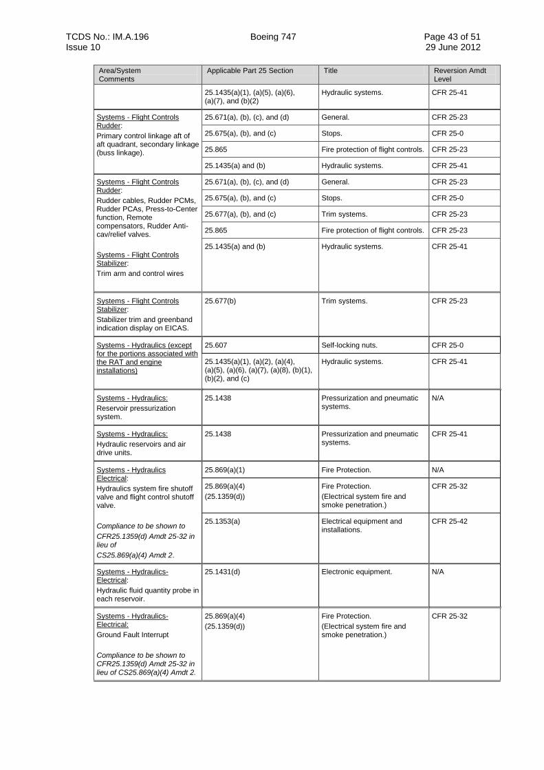
TCDS No.: IM.A.196 Boeing 747 Page 43 of 51 Issue 10 29 June 2012
Area/System Comments
Applicable Part 25 Section Title Reversion Amdt Level
25.1435(a)(1), (a)(5), (a)(6), (a)(7), and (b)(2)
Hydraulic systems. CFR 25-41
Systems - Flight Controls Rudder:
Primary control linkage aft of aft quadrant, secondary linkage (buss linkage).
25.671(a), (b), (c), and (d) General. CFR 25-23
25.675(a), (b), and (c) Stops. CFR 25-0
25.865 Fire protection of flight controls. CFR 25-23
25.1435(a) and (b) Hydraulic systems. CFR 25-41
Systems - Flight Controls Rudder:
Rudder cables, Rudder PCMs, Rudder PCAs, Press-to-Center function, Remote compensators, Rudder Anti-cav/relief valves.
Systems - Flight Controls Stabilizer:
Trim arm and control wires
25.671(a), (b), (c), and (d) General. CFR 25-23
25.675(a), (b), and (c) Stops. CFR 25-0
25.677(a), (b), and (c) Trim systems. CFR 25-23
25.865 Fire protection of flight controls. CFR 25-23
25.1435(a) and (b) Hydraulic systems. CFR 25-41
Systems - Flight Controls Stabilizer:
Stabilizer trim and greenband indication display on EICAS.
25.677(b) Trim systems. CFR 25-23
Systems - Hydraulics (except for the portions associated with the RAT and engine installations)
25.607 Self-locking nuts. CFR 25-0
25.1435(a)(1), (a)(2), (a)(4), (a)(5), (a)(6), (a)(7), (a)(8), (b)(1), (b)(2), and (c)
Hydraulic systems. CFR 25-41
Systems - Hydraulics:
Reservoir pressurization system.
25.1438 Pressurization and pneumatic systems.
N/A
Systems - Hydraulics:
Hydraulic reservoirs and air drive units.
25.1438 Pressurization and pneumatic systems.
CFR 25-41
Systems - Hydraulics Electrical:
Hydraulics system fire shutoff valve and flight control shutoff valve.
Compliance to be shown to
CFR25.1359(d) Amdt 25-32 in lieu of
CS25.869(a)(4) Amdt 2.
25.869(a)(1) Fire Protection. N/A
25.869(a)(4)
(25.1359(d))
Fire Protection.
(Electrical system fire and smoke penetration.)
CFR 25-32
25.1353(a) Electrical equipment and installations.
CFR 25-42
Systems - Hydraulics-Electrical:
Hydraulic fluid quantity probe in each reservoir.
25.1431(d) Electronic equipment. N/A
Systems - Hydraulics-Electrical:
Ground Fault Interrupt
Compliance to be shown to CFR25.1359(d) Amdt 25-32 in lieu of CS25.869(a)(4) Amdt 2.
25.869(a)(4)
(25.1359(d))
Fire Protection.
(Electrical system fire and smoke penetration.)
CFR 25-32
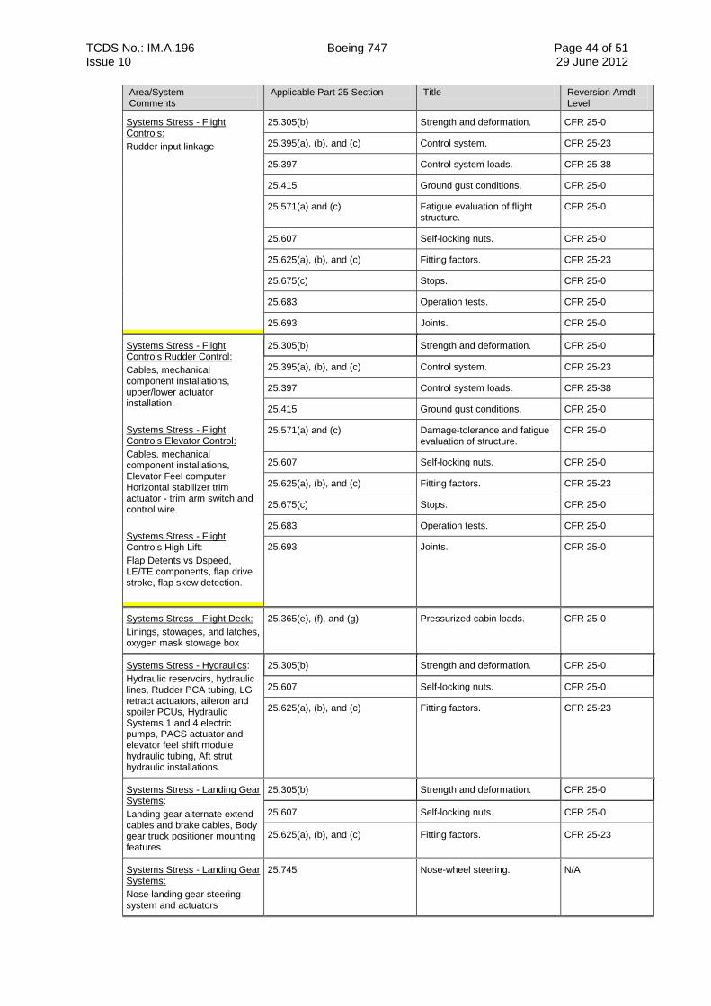
TCDS No.: IM.A.196 Boeing 747 Page 44 of 51 Issue 10 29 June 2012
Area/System Comments
Applicable Part 25 Section Title Reversion Amdt Level
Systems Stress - Flight Controls:
Rudder input linkage
25.305(b) Strength and deformation. CFR 25-0
25.395(a), (b), and (c) Control system. CFR 25-23
25.397 Control system loads. CFR 25-38
25.415 Ground gust conditions. CFR 25-0
25.571(a) and (c) Fatigue evaluation of flight structure.
CFR 25-0
25.607 Self-locking nuts. CFR 25-0
25.625(a), (b), and (c) Fitting factors. CFR 25-23
25.675(c) Stops. CFR 25-0
25.683 Operation tests. CFR 25-0
25.693 Joints. CFR 25-0
Systems Stress - Flight Controls Rudder Control:
Cables, mechanical component installations, upper/lower actuator installation.
Systems Stress - Flight Controls Elevator Control:
Cables, mechanical component installations, Elevator Feel computer. Horizontal stabilizer trim actuator - trim arm switch and control wire.
Systems Stress - Flight Controls High Lift:
Flap Detents vs Dspeed, LE/TE components, flap drive stroke, flap skew detection.
25.305(b) Strength and deformation. CFR 25-0
25.395(a), (b), and (c) Control system. CFR 25-23
25.397 Control system loads. CFR 25-38
25.415 Ground gust conditions. CFR 25-0
25.571(a) and (c) Damage-tolerance and fatigue evaluation of structure.
CFR 25-0
25.607 Self-locking nuts. CFR 25-0
25.625(a), (b), and (c) Fitting factors. CFR 25-23
25.675(c) Stops. CFR 25-0
25.683 Operation tests. CFR 25-0
25.693 Joints. CFR 25-0
Systems Stress - Flight Deck:
Linings, stowages, and latches, oxygen mask stowage box
25.365(e), (f), and (g) Pressurized cabin loads. CFR 25-0
Systems Stress - Hydraulics:
Hydraulic reservoirs, hydraulic lines, Rudder PCA tubing, LG retract actuators, aileron and spoiler PCUs, Hydraulic Systems 1 and 4 electric pumps, PACS actuator and elevator feel shift module hydraulic tubing, Aft strut hydraulic installations.
25.305(b) Strength and deformation. CFR 25-0
25.607 Self-locking nuts. CFR 25-0
25.625(a), (b), and (c) Fitting factors. CFR 25-23
Systems Stress - Landing Gear Systems:
Landing gear alternate extend cables and brake cables, Body gear truck positioner mounting features
25.305(b) Strength and deformation. CFR 25-0
25.607 Self-locking nuts. CFR 25-0
25.625(a), (b), and (c) Fitting factors. CFR 25-23
Systems Stress - Landing Gear Systems:
Nose landing gear steering system and actuators
25.745 Nose-wheel steering. N/A
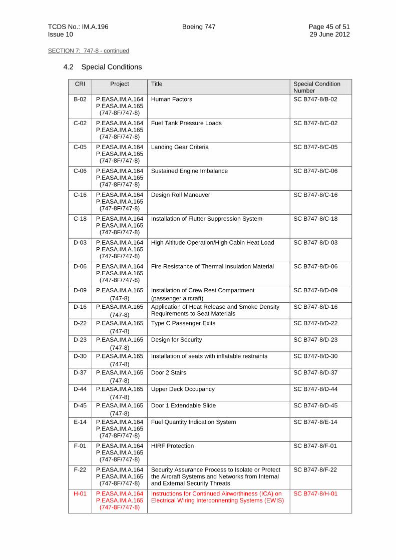
TCDS No.: IM.A.196 Boeing 747 Page 45 of 51 Issue 10 29 June 2012
SECTION 7: 747-8 - continued
4.2 Special Conditions
CRI Project Title Special Condition Number
B-02 P.EASA.IM.A.164 P.EASA.IM.A.165
(747-8F/747-8)
Human Factors SC B747-8/B-02
C-02 P.EASA.IM.A.164 P.EASA.IM.A.165
(747-8F/747-8)
Fuel Tank Pressure Loads SC B747-8/C-02
C-05 P.EASA.IM.A.164 P.EASA.IM.A.165
(747-8F/747-8)
Landing Gear Criteria SC B747-8/C-05
C-06 P.EASA.IM.A.164 P.EASA.IM.A.165
(747-8F/747-8)
Sustained Engine Imbalance SC B747-8/C-06
C-16 P.EASA.IM.A.164 P.EASA.IM.A.165
(747-8F/747-8)
Design Roll Maneuver SC B747-8/C-16
C-18 P.EASA.IM.A.164 P.EASA.IM.A.165
(747-8F/747-8)
Installation of Flutter Suppression System SC B747-8/C-18
D-03 P.EASA.IM.A.164 P.EASA.IM.A.165
(747-8F/747-8)
High Altitude Operation/High Cabin Heat Load SC B747-8/D-03
D-06 P.EASA.IM.A.164 P.EASA.IM.A.165
(747-8F/747-8)
Fire Resistance of Thermal Insulation Material SC B747-8/D-06
D-09 P.EASA.IM.A.165
(747-8)
Installation of Crew Rest Compartment
(passenger aircraft)
SC B747-8/D-09
D-16 P.EASA.IM.A.165
(747-8)
Application of Heat Release and Smoke Density Requirements to Seat Materials
SC B747-8/D-16
D-22 P.EASA.IM.A.165
(747-8)
Type C Passenger Exits SC B747-8/D-22
D-23 P.EASA.IM.A.165
(747-8)
Design for Security SC B747-8/D-23
D-30 P.EASA.IM.A.165
(747-8)
Installation of seats with inflatable restraints SC B747-8/D-30
D-37 P.EASA.IM.A.165
(747-8)
Door 2 Stairs SC B747-8/D-37
D-44 P.EASA.IM.A.165
(747-8)
Upper Deck Occupancy SC B747-8/D-44
D-45 P.EASA.IM.A.165
(747-8)
Door 1 Extendable Slide SC B747-8/D-45
E-14 P.EASA.IM.A.164 P.EASA.IM.A.165
(747-8F/747-8)
Fuel Quantity Indication System SC B747-8/E-14
F-01 P.EASA.IM.A.164 P.EASA.IM.A.165
(747-8F/747-8)
HIRF Protection SC B747-8/F-01
F-22 P.EASA.IM.A.164 P.EASA.IM.A.165
(747-8F/747-8)
Security Assurance Process to Isolate or Protect the Aircraft Systems and Networks from Internal and External Security Threats
SC B747-8/F-22
H-01 P.EASA.IM.A.164 P.EASA.IM.A.165
(747-8F/747-8)
Instructions for Continued Airworthiness (ICA) on Electrical Wiring Interconnenting Systems (EWIS)
SC B747-8/H-01
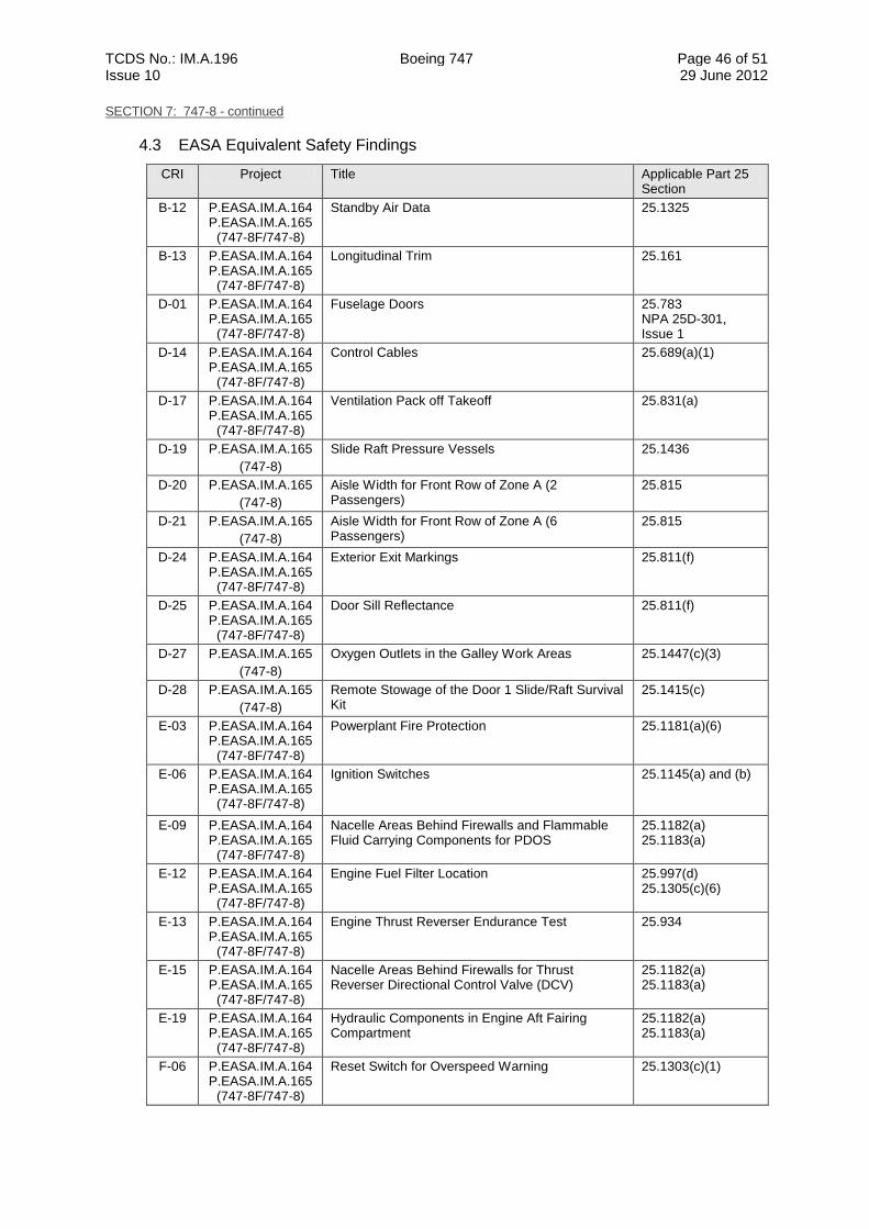
TCDS No.: IM.A.196 Boeing 747 Page 46 of 51 Issue 10 29 June 2012
SECTION 7: 747-8 - continued
4.3 EASA Equivalent Safety Findings
CRI Project Title Applicable Part 25 Section
B-12 P.EASA.IM.A.164 P.EASA.IM.A.165
(747-8F/747-8)
Standby Air Data 25.1325
B-13 P.EASA.IM.A.164 P.EASA.IM.A.165
(747-8F/747-8)
Longitudinal Trim 25.161
D-01 P.EASA.IM.A.164 P.EASA.IM.A.165
(747-8F/747-8)
Fuselage Doors 25.783 NPA 25D-301, Issue 1
D-14 P.EASA.IM.A.164 P.EASA.IM.A.165
(747-8F/747-8)
Control Cables 25.689(a)(1)
D-17 P.EASA.IM.A.164 P.EASA.IM.A.165
(747-8F/747-8)
Ventilation Pack off Takeoff 25.831(a)
D-19 P.EASA.IM.A.165
(747-8)
Slide Raft Pressure Vessels 25.1436
D-20 P.EASA.IM.A.165
(747-8)
Aisle Width for Front Row of Zone A (2 Passengers)
25.815
D-21 P.EASA.IM.A.165
(747-8)
Aisle Width for Front Row of Zone A (6 Passengers)
25.815
D-24 P.EASA.IM.A.164 P.EASA.IM.A.165
(747-8F/747-8)
Exterior Exit Markings 25.811(f)
D-25 P.EASA.IM.A.164 P.EASA.IM.A.165
(747-8F/747-8)
Door Sill Reflectance 25.811(f)
D-27 P.EASA.IM.A.165
(747-8)
Oxygen Outlets in the Galley Work Areas 25.1447(c)(3)
D-28 P.EASA.IM.A.165
(747-8)
Remote Stowage of the Door 1 Slide/Raft Survival Kit
25.1415(c)
E-03 P.EASA.IM.A.164 P.EASA.IM.A.165
(747-8F/747-8)
Powerplant Fire Protection 25.1181(a)(6)
E-06 P.EASA.IM.A.164 P.EASA.IM.A.165
(747-8F/747-8)
Ignition Switches 25.1145(a) and (b)
E-09 P.EASA.IM.A.164 P.EASA.IM.A.165
(747-8F/747-8)
Nacelle Areas Behind Firewalls and Flammable Fluid Carrying Components for PDOS
25.1182(a) 25.1183(a)
E-12 P.EASA.IM.A.164 P.EASA.IM.A.165
(747-8F/747-8)
Engine Fuel Filter Location 25.997(d) 25.1305(c)(6)
E-13 P.EASA.IM.A.164 P.EASA.IM.A.165
(747-8F/747-8)
Engine Thrust Reverser Endurance Test 25.934
E-15 P.EASA.IM.A.164 P.EASA.IM.A.165
(747-8F/747-8)
Nacelle Areas Behind Firewalls for Thrust Reverser Directional Control Valve (DCV)
25.1182(a) 25.1183(a)
E-19 P.EASA.IM.A.164 P.EASA.IM.A.165
(747-8F/747-8)
Hydraulic Components in Engine Aft Fairing Compartment
25.1182(a) 25.1183(a)
F-06 P.EASA.IM.A.164 P.EASA.IM.A.165
(747-8F/747-8)
Reset Switch for Overspeed Warning 25.1303(c)(1)
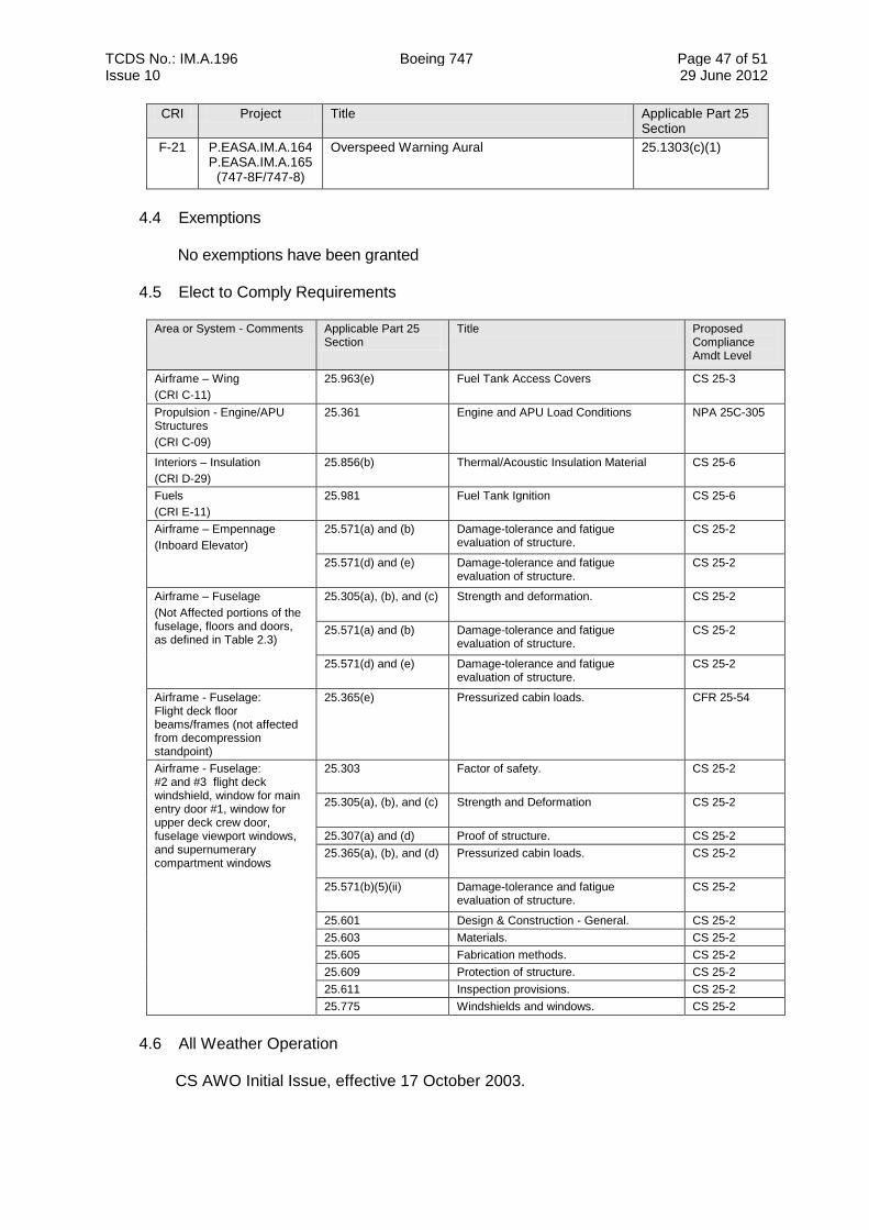
TCDS No.: IM.A.196 Boeing 747 Page 47 of 51 Issue 10 29 June 2012
CRI Project Title Applicable Part 25 Section
F-21 P.EASA.IM.A.164 P.EASA.IM.A.165
(747-8F/747-8)
Overspeed Warning Aural 25.1303(c)(1)
4.4 Exemptions
No exemptions have been granted
4.5 Elect to Comply Requirements
Area or System - Comments Applicable Part 25 Section
Title Proposed Compliance Amdt Level
Airframe – Wing
(CRI C-11)
25.963(e) Fuel Tank Access Covers CS 25-3
Propulsion - Engine/APU Structures
(CRI C-09)
25.361 Engine and APU Load Conditions NPA 25C-305
Interiors – Insulation
(CRI D-29)
25.856(b) Thermal/Acoustic Insulation Material CS 25-6
Fuels
(CRI E-11)
25.981 Fuel Tank Ignition CS 25-6
Airframe – Empennage
(Inboard Elevator)
25.571(a) and (b) Damage-tolerance and fatigue evaluation of structure.
CS 25-2
25.571(d) and (e) Damage-tolerance and fatigue evaluation of structure.
CS 25-2
Airframe – Fuselage
(Not Affected portions of the fuselage, floors and doors, as defined in Table 2.3)
25.305(a), (b), and (c) Strength and deformation. CS 25-2
25.571(a) and (b) Damage-tolerance and fatigue evaluation of structure.
CS 25-2
25.571(d) and (e) Damage-tolerance and fatigue evaluation of structure.
CS 25-2
Airframe - Fuselage: Flight deck floor beams/frames (not affected from decompression standpoint)
25.365(e) Pressurized cabin loads. CFR 25-54
Airframe - Fuselage: #2 and #3 flight deck windshield, window for main entry door #1, window for upper deck crew door, fuselage viewport windows, and supernumerary compartment windows
25.303 Factor of safety. CS 25-2
25.305(a), (b), and (c) Strength and Deformation CS 25-2
25.307(a) and (d) Proof of structure. CS 25-2
25.365(a), (b), and (d) Pressurized cabin loads. CS 25-2
25.571(b)(5)(ii) Damage-tolerance and fatigue evaluation of structure.
CS 25-2
25.601 Design & Construction - General. CS 25-2
25.603 Materials. CS 25-2
25.605 Fabrication methods. CS 25-2
25.609 Protection of structure. CS 25-2
25.611 Inspection provisions. CS 25-2
25.775 Windshields and windows. CS 25-2
4.6 All Weather Operation
CS AWO Initial Issue, effective 17 October 2003.
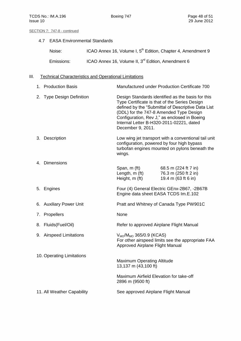
TCDS No.: IM.A.196 Boeing 747 Page 48 of 51 Issue 10 29 June 2012
SECTION 7: 747-8 - continued
4.7 EASA Environmental Standards
Noise: ICAO Annex 16, Volume I, 5
th Edition, Chapter 4, Amendment 9
Emissions: ICAO Annex 16, Volume II, 3
rd Edition, Amendment 6
III. Technical Characteristics and Operational Limitations
1. Production Basis Manufactured under Production Certificate 700 2. Type Design Definition Design Standards identified as the basis for this
Type Certificate is that of the Series Design defined by the “Submittal of Descriptive Data List (DDL) for the 747-8 Amended Type Design Configuration, Rev J,” as enclosed in Boeing Internal Letter B-H320-2011-02221, dated December 9, 2011.
3. Description Low wing jet transport with a conventional tail unit configuration, powered by four high bypass turbofan engines mounted on pylons beneath the wings.
4. Dimensions Span, m (ft) 68.5 m (224 ft 7 in) Length, m (ft) 76.3 m (250 ft 2 in) Height, m (ft) 19.4 m (63 ft 6 in)
5. Engines Four (4) General Electric GEnx-2B67, -2B67B
Engine data sheet EASA TCDS Im.E.102
6. Auxiliary Power Unit Pratt and Whitney of Canada Type PW901C
7. Propellers None
8. Fluids(Fuel/Oil) Refer to approved Airplane Flight Manual
9. Airspeed Limitations VMO/MMO 365/0.9 (KCAS) For other airspeed limits see the appropriate FAA Approved Airplane Flight Manual
10. Operating Limitations Maximum Operating Altitude 13,137 m (43,100 ft) Maximum Airfield Elevation for take-off 2896 m (9500 ft)
11. All Weather Capability See approved Airplane Flight Manual
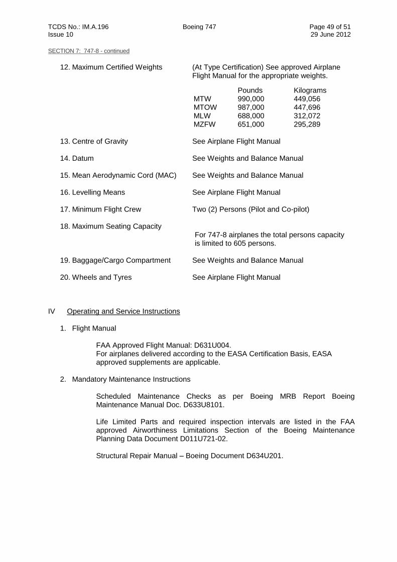
TCDS No.: IM.A.196 Boeing 747 Page 49 of 51 Issue 10 29 June 2012
SECTION 7: 747-8 - continued
12. Maximum Certified Weights (At Type Certification) See approved Airplane
Flight Manual for the appropriate weights.
Pounds Kilograms MTW 990,000 449,056 MTOW 987,000 447,696 MLW 688,000 312,072 MZFW 651,000 295,289
13. Centre of Gravity See Airplane Flight Manual 14. Datum See Weights and Balance Manual
15. Mean Aerodynamic Cord (MAC) See Weights and Balance Manual
16. Levelling Means See Airplane Flight Manual 17. Minimum Flight Crew Two (2) Persons (Pilot and Co-pilot)
18. Maximum Seating Capacity
For 747-8 airplanes the total persons capacity is limited to 605 persons.
19. Baggage/Cargo Compartment See Weights and Balance Manual
20. Wheels and Tyres See Airplane Flight Manual
IV Operating and Service Instructions
1. Flight Manual
FAA Approved Flight Manual: D631U004. For airplanes delivered according to the EASA Certification Basis, EASA approved supplements are applicable.
2. Mandatory Maintenance Instructions
Scheduled Maintenance Checks as per Boeing MRB Report Boeing Maintenance Manual Doc. D633U8101.
Life Limited Parts and required inspection intervals are listed in the FAA approved Airworthiness Limitations Section of the Boeing Maintenance Planning Data Document D011U721-02. Structural Repair Manual – Boeing Document D634U201.
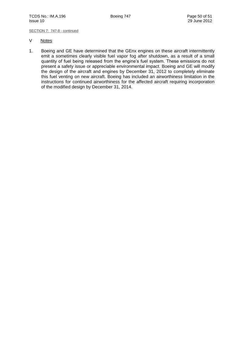
TCDS No.: IM.A.196 Boeing 747 Page 50 of 51 Issue 10 29 June 2012
SECTION 7: 747-8 - continued
V Notes 1. Boeing and GE have determined that the GEnx engines on these aircraft intermittently
emit a sometimes clearly visible fuel vapor fog after shutdown, as a result of a small quantity of fuel being released from the engine’s fuel system. These emissions do not present a safety issue or appreciable environmental impact. Boeing and GE will modify the design of the aircraft and engines by December 31, 2012 to completely eliminate this fuel venting on new aircraft. Boeing has included an airworthiness limitation in the instructions for continued airworthiness for the affected aircraft requiring incorporation of the modified design by December 31, 2014.
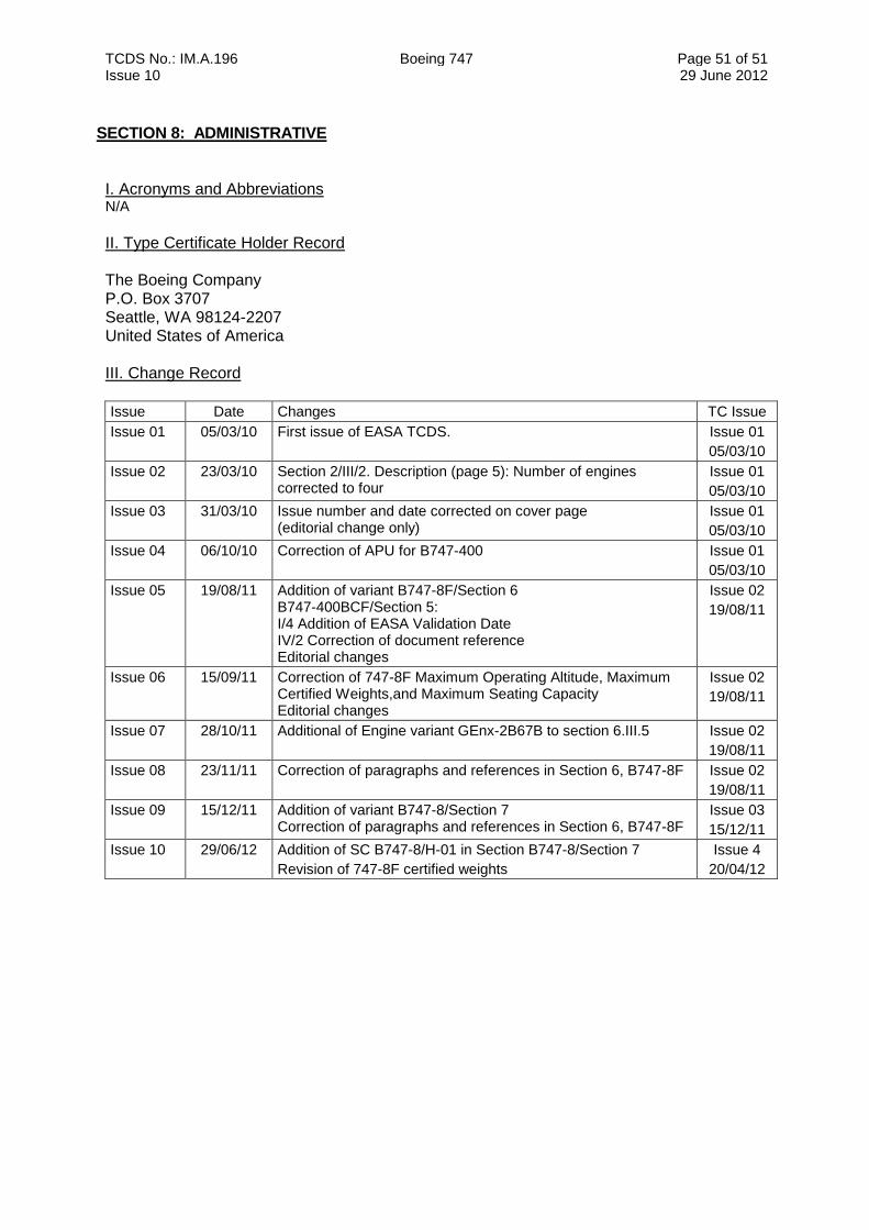
TCDS No.: IM.A.196 Boeing 747 Page 51 of 51 Issue 10 29 June 2012
SECTION 8: ADMINISTRATIVE I. Acronyms and Abbreviations N/A
II. Type Certificate Holder Record The Boeing Company P.O. Box 3707 Seattle, WA 98124-2207 United States of America III. Change Record
Issue Date Changes TC Issue
Issue 01 05/03/10 First issue of EASA TCDS. Issue 01
05/03/10
Issue 02 23/03/10 Section 2/III/2. Description (page 5): Number of engines corrected to four
Issue 01
05/03/10
Issue 03 31/03/10 Issue number and date corrected on cover page (editorial change only)
Issue 01
05/03/10
Issue 04 06/10/10 Correction of APU for B747-400 Issue 01
05/03/10
Issue 05 19/08/11 Addition of variant B747-8F/Section 6 B747-400BCF/Section 5: I/4 Addition of EASA Validation Date IV/2 Correction of document reference Editorial changes
Issue 02
19/08/11
Issue 06 15/09/11 Correction of 747-8F Maximum Operating Altitude, Maximum Certified Weights,and Maximum Seating Capacity Editorial changes
Issue 02
19/08/11
Issue 07 28/10/11 Additional of Engine variant GEnx-2B67B to section 6.III.5
Issue 02
19/08/11
Issue 08 23/11/11 Correction of paragraphs and references in Section 6, B747-8F Issue 02
19/08/11
Issue 09 15/12/11 Addition of variant B747-8/Section 7 Correction of paragraphs and references in Section 6, B747-8F
Issue 03
15/12/11
Issue 10 29/06/12 Addition of SC B747-8/H-01 in Section B747-8/Section 7
Revision of 747-8F certified weights
Issue 4
20/04/12